ICOM orporated 325400 VHF Transceiver User Manual 1
ICOM Incorporated VHF Transceiver 1
UserManual.wiki
>
ICOM orporated
>
325400 User Manual
>
User Manual 1
Contents
1.
User Manual 1
2.
User Manual 2
User Manual 1
Navigation menu
Upload a User Manual
Namespaces
Wiki Guide
HTML
PDF
Info
Views
User Manual
Discussion / Help
Navigation
![iiRWARNING RF EXPOSURE! This device emits Radio Frequency (RF) energy. Caution should be observed when operating this device. If you have any questions re-garding RF exposure and safety standards, please refer to the Federal Communications Commission Office of Engi-neering and Technology’s report on Evaluating Compliance with FCC Guidelines for Human Radio Frequency Electro-magnetic Fields (OET Bulletin 65)RWARNING! NEVER hold the transceiver so that the antenna is very close to, or touching exposed parts of the body, especially the face or eyes, while transmitting. The transceiver will perform best if the microphone is 5 to 10 cm (2 to 4 inches) away from the lips and the transceiver is ver-tical.RWARNING! NEVER operate the transceiver with a headset or other audio accessories at high volume levels. Hearing experts advise against continuous high volume op-eration. If you experience a ringing in your ears, reduce the volume level or discontinue use.RWARNING! NEVER operate the transceiver while driving a vehicle. Safe driving requires your full attention—anything less may result in an accident.NEVER connect the transceiver to a power source using reverse polarity. This will ruin the transceiver.DO NOT operate the transceiver near unshielded electri-cal blasting caps or in an explosive atmosphere.DO NOT push [PTT] unless you actually intend to trans-mit.BE CAREFUL! The transceiver will become hot when operating it continuously for long periods.DO NOT use or place the transceiver in direct sunlight or in areas with temperatures below –20°C (–4˚F) or above +60°C (+140˚F).Place the unit in a secure place to avoid inadvertent use by children.DO NOT use harsh solvents such as benzene or alco-hol to clean the transceiver, because they can damage the transceiver’s surfaces.PRECAUTIONS](https://usermanual.wiki/ICOM-orporated/325400.User-Manual-1/User-Guide-1203017-Page-3.png)
![vTABLE OF CONTENTSFOREWORD ..................................................................................... iFEATURES ........................................................................................ iEXPLICIT DEFINITIONS ................................................................... iIMPORTANT ...................................................................................... iPRECAUTIONS ............................................................................ii–iiiFCC INFORMATION ....................................................................... iiiSUPPLIED ACCESSORIES ............................................................ ivTABLE OF CONTENTS ............................................................... v–vi1 ACCESSORIES ...........................................................1–2 ■ Antenna ...................................................................................1 ■ Belt clip ....................................................................................1 ■ Battery pack/case ....................................................................2 ■ Jack cover ................................................................................22 PANEL DESCRIPTION ................................................3–7 ■■ Front, top and side panels .......................................................3 ■ Function display .......................................................................63 BATTERY CHARGING ..............................................8–13 ■ Caution (for the BP-264 Ni-MH battery) ................................... 8 ■ Caution (for the BP-265 Li-Ion battery) .................................... 9 ■ Battery chargers ....................................................................11 ■ Battery case (BP-263) ............................................................... 13 ■ Battery information ................................................................134 BASIC OPERATION ................................................14–19 ■ Power ON ..............................................................................14 ■ Adjusting the volume level .....................................................14 ■ Adjusting the squelch level ....................................................14 ■ Monitor function .....................................................................14 ■ Mode selection.......................................................................15 ■ Operating mode selection ......................................................16 ■ Setting a tuning step ..............................................................16 ■ Setting a frequency ................................................................16 ■ Receiving ...............................................................................17 ■ Transmitting ............................................................................17 ■ Key lock function ....................................................................18 ■ [VOL] function assignment .....................................................18 ■ Weather channel operation (U.S.A. version only) ..................195 REPEATER AND DUPLEX OPERATION ...............20–23 ■ Repeater operation ................................................................20 ■ Duplex operation ....................................................................21 ■ Subaudible tones ...................................................................22 ■ Lockout function .....................................................................23 ■ Auto repeater function (U.S.A. version only) .........................236 MEMORY/CALL OPERATION ................................24–28 ■ General description................................................................24 ■ Selecting a memory channel .................................................24 ■ Selecting the Call channel .....................................................24 ■ Channel programming ...........................................................25 ■ Copying memory/Call contents .............................................. 26 ■ Clearing memory contents .............................................................27 ■ Display type ........................................................................... 27 ■ Programming a channel name .................................................28](https://usermanual.wiki/ICOM-orporated/325400.User-Manual-1/User-Guide-1203017-Page-6.png)
![21■ Battery pack/caseTo attach the battery pack/case:q Fit the battery pack/case in the direction of the arrow (q), then close.w Hook the latch until it makes a ‘click’ sound (w).To remove the battery pack/case:➥ Unhook the latch (e), and lift up the battery pack/case in the direction of the arrow (r).NEVER remove or attach the battery pack/case when the transceiver is wet or soiled. This may result in water or dust getting into the transceiver/battery pack/case, and may result in them being damaged.NOTE: Keep the battery terminals clean. It’s a good idea to clean the battery terminals once a week.■ Jack coverAttach the jack cover when optional equipment is not used.1ACCESSORIES2345678910111213141516171819To attach the jack coverq Attach the jack cover to the [SP MIC] jack.w Tighten the screws.To detach the jack covere Remove the screws with a phillips screwdriver.r Detach the jack cover to connect optional equip-ment.wqLatchBattery pack/caseerrwwqeeBe careful! The latch is tightly locked, so use caution when releasing it. DO NOT use your finger nail. Use the edge of a coin or screwdriver tip to carefully release it.](https://usermanual.wiki/ICOM-orporated/325400.User-Manual-1/User-Guide-1203017-Page-9.png)
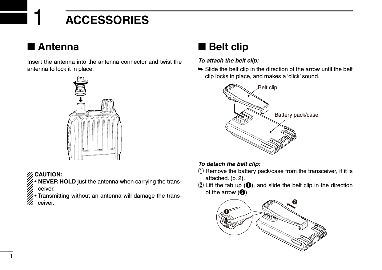
![3PANEL DESCRIPTION2■ Front, top and side panelsq PTT SWITCH [PTT]➥ Push and hold to transmit, release to receive. (p. 17)For IC-V80E only➥ Push briefly, then push and hold to transmit a 1750 Hz tone burst signal. (p. 22)w ANTENNA CONNECTORConnect the antenna here. (p. 1)e CONTROL DIAL [VOL]➥ Adjust the volume level. (p. 14)➥ During the Set mode, or Initial Set mode, rotate to se-lect a desired option or value. (pp. 38, 43) r EXTERNAL SPEAKER/MICROPHONE JACKS [SP MIC]Used to connect an optional speaker-microphone, plug adapter cable or cloning cable. The internal microphone and speaker will not function when an option is con-nected. See page 51 for a list of available options. Be sure to turn power OFF before connecting/discon-necting optional equipment to/from the [SP/MIC] jack.t MONITOR KEY [MONI]➥ Push and hold to open the squelch temporarily to mon-itor the operating frequency. (p. 14)➥ While pushing and holding this key, push [] or [] to adjust the squelch level. (p. 14)➥ Enters or sends the DTMF code ‘A.’ (pp. 35, 36)qwertyuiFunctiondisplay (p. 6)Keypad (p. 4)MicrophoneSpeaker](https://usermanual.wiki/ICOM-orporated/325400.User-Manual-1/User-Guide-1203017-Page-10.png)
![42y POWER KEY [ ]Push and hold for 1 sec. to turn the transceiver power ON or OFF. (p. 14)u UP/DOWN KEYS []/[]➥ Push to change the operating frequency. (p. 16)➥ During memory mode operation, push to select a memory channel. (p. 24)➥ While scanning, push to change the scanning direction. (pp. 29, 30, 31, 34)➥ While pushing and holding [MONI], push to set the squelch level. (p. 14)➥ During the Set mode, or Initial Set mode, push to se-lect a desired setting item. (pp. 38, 43)➥ [] enters or sends the DTMF code ‘B.’ (pp. 35, 36)➥ [] enters or sends the DTMF code ‘C.’ (pp. 35, 36)i VFO/MEMORY/CALL KEY [VFO/MR/CALL]➥ Push to select the VFO mode, memory mode, a Call channel and a weather channel*, in sequence. (p. 15)*Only the U.S.A. version transceivers.➥ After pushing [FUNC](M), push to enter the memory programming mode.➥ After pushing [FUNC](M), push and hold for 1 sec. to transfer a channel contents to a memory channel, or to the VFO mode. (p. 26)➥ Enters or sends the DTMF code ‘D.’ (pp. 35, 36) The functions of [VOL] and []/[] can be exchanged. See page 18 for details. D KEYPAD➥ Push to input numbers for frequency input and memory channel selection.➥ Push to enter or send the DTMF code. (pp. 35, 36)➥ To activate the second function of a key, first push [FUNC](M), and then push the key.[1] • [ TONE](1)➥ Numeric input and DTMF code: ‘1’➥ After pushing [FUNC](M), selects the Tone func-tion. (p. 33)[2] • [VOX](2)➥ Numeric input and DTMF code: ‘2’➥ After pushing [FUNC](M), turns the VOX function ON or OFF*. (p. 52)* Only when an optional headset and plug adapter are connected.2PANEL DESCRIPTION1345678910111213141516171819](https://usermanual.wiki/ICOM-orporated/325400.User-Manual-1/User-Guide-1203017-Page-11.png)
![5[3] • [T.SCAN](3)➥ Numeric input and DTMF code: ‘3’➥ After pushing [FUNC](M), starts a tone scan. (p. 34)[4] • [DUP](4)➥ Numeric input and DTMF code: ‘4’➥ After pushing [FUNC](M), selects minus duplex, plus duplex, or simplex operation. (p. 21)[5] • [SCAN](5)➥ Numeric input and DTMF code: ‘5’➥ After pushing [FUNC](M), starts a scan. (pp. 29, 30)[6] • [SKIP](6)➥ Numeric input and DTMF code: ‘6’➥ After pushing [FUNC](M), sets or cancels the skip setting. (p. 30)[7] • [PRIO](7)➥ Numeric input and DTMF code: ‘7’➥ After pushing [FUNC](M), starts a priority watch. (p. 31)[8] • [SET](8)➥ Numeric input and DTMF code: ‘8’➥ After pushing [FUNC](M), enters the Set mode. (p. 38)[9] • [H/M/L](9)➥ Numeric input and DTMF code: ‘9’➥ After pushing [FUNC](M), selects the output power between high, middle and low. (p. 17)[0] • [DTMF-M](0)➥ Numeric input and DTMF code: ‘0’➥ After pushing [FUNC](M), enters the DTMF memory mode. (p. 35)[M] • [FUNC](M)➥ DTMF code: ‘M (indication: E)’ ➥ Push to access the second function of other keys.[# ENT] • [ ](# ENT)➥ DTMF code: ‘# (indication: F)’➥ After entering a frequency, stores the frequency. (p. 16)➥ Push to exit the Set mode or Initial Set mode. (pp. 38, 43)➥ After pushing [FUNC](M), push and hold for 1 sec. to turn the key lock function ON or OFF (p. 18)2PANEL DESCRIPTION](https://usermanual.wiki/ICOM-orporated/325400.User-Manual-1/User-Guide-1203017-Page-12.png)
![1434■ Power ON➥ Push and hold [ ] for 1 sec. to turn the power ON.• Push and hold [ ] for 1 sec. to turn the power OFF.■ Adjusting the volume level➥ Rotate [VOL] to adjust the volume level. • If the squelch is closed, push and hold [MONI] while adjusting the volume level.• The display shows the volume level while adjusting.■ Adjusting the squelch level➥ While pushing and holding [MONI], push [] or [] sev-eral times to adjust the squelch level. • “SqL 1” is loose squelch (for weak signals) and “SqL10” is tight squelch (for strong signals). “SqL 0” is open squelch.■ Monitor functionThis function is used to listen to weak signals or to open the squelch manually. You can use it without disturbing the squelch setting, even when mute functions such as the tone squelch are in use.➥ Push and hold [MONI] to monitor the operating frequency.• “ ” blinks while the monitor function is ON.4BASIC OPERATION125678910111213141516171819](https://usermanual.wiki/ICOM-orporated/325400.User-Manual-1/User-Guide-1203017-Page-21.png)
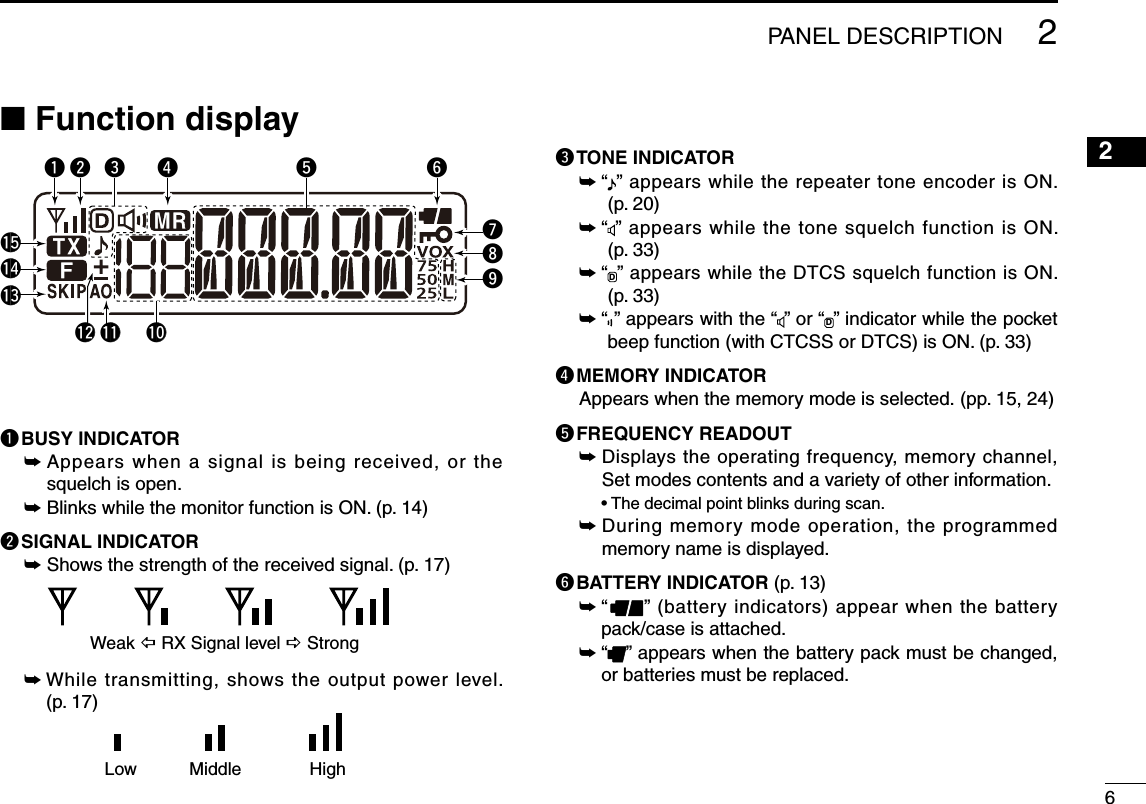
![15■ Mode selection➥ Pus h [VFO/MR/CALL] several times to select the VFO mode, memory mode, Call channel mode and weather channel mode*, in se-quence. *For only the U.S.A. version transceivers.D VFO modeThe VFO mode is used to set the operating frequency.What is VFO?VFO is an abbreviation of Variable Frequency Oscillator. Fre-quencies for both transmitting and receiving are generated and controlled by the VFO.D Memory modeThe memory mode is used for operating on memory channels, which store programmed fre-quencies.• “ ” appears when the memory mode is selected.D Call channel modeThe Call channel is used for quick recall of the most often-used frequency.• “C” appears instead of the memory channel number when the Call channel mode is selected.D Weather channel mode*There are 10 weather channels for monitoring weather broad-casts from NOAA (National Oceanic and Atmospheric Ad-ministration).* Only for the U.S.A. version trans-ceivers.• Memory mode displayAppears• VFO mode displayAppears• Call channel mode display• Weather channel mode display4BASIC OPERATION](https://usermanual.wiki/ICOM-orporated/325400.User-Manual-1/User-Guide-1203017-Page-22.png)
 then [SET](8) to enter the Set mode.w Push [] or [] to select the operating mode item. (W/n)e Rotate [VOL] to set the operating mode to FM or FM-N.r Push [# ENT] to exit the Set mode.■ Setting a tuning stepThe transceiver has 8 tuning step options;• 5 kHz • 10 kHz • 12.5 kHz • 15 kHz • 20 kHz • 25 kHz • 30 kHz • 50 kHzThe tuning step can be selected in the Set mode.q Push [FUNC](M), and then [SET](8) to enter the Set mode.w Push [] or [] to select the tuning step item. (tS)e Rotate [VOL] to select the desired tuning step.r Push [# ENT] to exit the Set mode.■ Setting a frequencyD Using [] or []q Push [VFO/MR/CALL] several times to select the VFO mode.w Push [] or [] to select the desired frequency.• The frequency changes according to the preset tuning steps. See the previous topic to set the tuning step.D Using the keypadq Push [VFO/MR/CALL] several times to select the VFO mode.w To enter the desired frequency, enter 6 digits, starting from 100 MHz digit.• Entering two or three* to five digits, and then pushing [# ENT], also sets the frequency. (*Depending on the version)• If a frequency outside the frequency range is entered, the previ-ously displayed frequency is automatically recalled.• Example 1— entering 145.525 MHzPush• Example 2— entering 144.800 MHzPush20 kHz tuning stepFM mode FM-N mode4BASIC OPERATION1235678910111213141516171819](https://usermanual.wiki/ICOM-orporated/325400.User-Manual-1/User-Guide-1203017-Page-23.png)
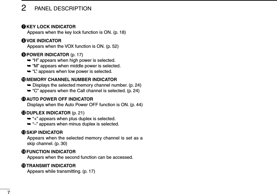
![17■ ReceivingMake sure the BP-264 or BP-265 battery pack is fully charged, or the BP-263 battery case has brand new alkaline batteries (pp. 11–13).q Push and hold [ ] for 1 sec. to turn power ON.w Rotate [VOL] to set the desired volume level. (p. 14)• The volume level is displayed on the LCD while adjusting.e Set the receive frequency. (p. 16)r Set the squelch level. (p. 14)• While pushing and holding [MONI], push [] or [].• The squelch level is displayed on the LCD while setting.• “SqL 1” is loose squelch (for weak signals) and “SqL10” is tight squelch (for strong signals). “SqL 0” is open squelch.• Push and hold [MONI] to open the squelch manually.t When a signal is received:• The squelch is opened and the audio is heard.• The signal indicator shows the relative signal strength level.■ TransmittingCAUTION: Transmitting without an antenna will damage the transceiver.NOTE: To prevent interference, push and hold [MONI] to listen on the frequency before transmitting.q Set the operating frequency. (p. 16)w Push [FUNC](M), and then push [H/M/L](9) to select the output power between High (5.5 W), Mid (2.5 W) and Low (0.5 W).• “ H,” “M,” or “ L” appears according to the selected output power.e Push and hold [PTT] to transmit.• “ ” appears while transmitting.• The signal indicator shows the output power level.r Speak into the microphone using your normal voice level.• DO NOT hold the transceiver too close to your mouth or speak too loudly. This may distort your speech.t Release [PTT] to return to receive.4BASIC OPERATIONw Adjust the volume level.r For the squelch level setting. (Push to monitor)q Turn the power ON.e Set the frequency.r Adjust the squelch level.Microphone w Select theoutput power.Push to monitor.q Set the frequency.e Push and hold to transmit.t Release to receive.](https://usermanual.wiki/ICOM-orporated/325400.User-Manual-1/User-Guide-1203017-Page-24.png)
, and then push and hold [ ](# ENT) for 1 sec. to turn the key lock function ON or OFF.• “ ” appears while the key lock function is activated.• [ ], [VOL], [MONI], [PTT] and [FUNC](M) + [ ](# ENT) are still operable while the key lock function is ON.■ [VOL] function assignment[VOL] can be used as a tuning control instead of [] and [], to suit your preference. However, when [VOL] functions as a tuning control, [] and [] function as volume controls.q While pushing and holding [] and [], turn the power ON to enter the Initial Set mode.w Push [] or [] to select the dial assignment item. (tOP)e Rotate [VOL] to select an option.r Push [# ENT] to exit the Initial Set mode. [VOL] and []/[] function as described below, depend-ing on the option.Appears[VOL] [VOL] functions as the volume control. [VOL] functions as the tuning control. 4BASIC OPERATIONOption [VOL] []/[]tOP.VO Volume control Tuning controlstOP.di Tuning control Volume controls1235678910111213141516171819](https://usermanual.wiki/ICOM-orporated/325400.User-Manual-1/User-Guide-1203017-Page-25.png)
![19■ Weather channel operationThere are 10 weather channels for monitoring weather broadcasts from NOAA (National Oce-anic and Atmospheric Administration).D Weather channel selectionq Push [VFO/MR/CALL] several times to select the weather channel mode.w Push [] or [] to select a weather channel.e Push [VFO/MR/CALL] to return to the previous frequency or memory channel.D Weather alert functionNOAA broadcast stations transmit weather alert tones be-fore important weather announcements. When the weather alert function is ON, the selected weather channel is moni-tored every 5 sec. for announcements. When the alert signal is detected, the “ALt” and the WX channel number are alter-nately displayed, and a beep sounds until the transceiver is operated. The previously selected (used) weather channel is checked periodically during standby, or while scanning.q Select a weather channel.w Turn the weather alert function ON in the Set mode. ➥ Push [FUNC](M), and then [SET](8) to enter the Set mode. ➥ Push [] or [] to select the weather alert item. (ALt) ➥ Rotate [VOL] to select “ON.” ➥ Push [# ENT] to exit the Set mode.e Set the desired stand-by mode.• Select the VFO, memory or Call channel mode.• Scan or priority watch operation can also be selected.r When an alert is detected, a beep sounds, and “ALt” and the weather channel number will be alternately displayed.t Turn the weather alert function OFF in the Set mode.NOTE: While receiving a signal on a frequency other than the Weather alert frequency, the receiving signal will be interrupted momentarily approximately every 5 sec. when the weather alert function is ON. These interruptions cease when the weather alert function is turned OFF.Push [FUNC](M), and then [SCAN](5) to start a weather channel scan. Push any key except []/[], [FUNC](M) and [MONI] to stop the scan.U.S.A. version only4BASIC OPERATION• Weather channel mode display](https://usermanual.wiki/ICOM-orporated/325400.User-Manual-1/User-Guide-1203017-Page-26.png)
, and then [DUP](4) several times to set the shift direction of the transmit frequency. ( “–” or “+”; See page 21 for details.)• When the auto repeater function is in use (U.S.A. version only), this selection and step e are not necessary. (p. 23).e If desired, push [FUNC](M) and then [TONE](1) several times to activate the subaudible tone encoder. • “ ” appears. • Select the desired subaudible tone frequency. (p. 22)r Push and hold [PTT] to transmit.• The displayed frequency automatically changes to the transmit frequency (repeater input frequency).• If “OFF” appears, check the frequency offset and shift direction (p. 21).t Release [PTT] to receive.y Push and hold [MONI] to check whether the other station’s transmit signal can be directly received or not.• When the other station’s signal can be directly received, move to a non-repeater frequency to use simplex. (duplex OFF)For the U.S.A. version:Auto repeater function uses standard values of the re-peater tone frequency and frequency offset.Station A Station BRepeater145.300 MHz144.700 MHz 144.700 MHz145.300 MHzUplinkDownlink(transmit freq.)(receive freq.)5REPEATER AND DUPLEX OPERATIONAppearsWhile receiving While transmitting123678910111213141516171819](https://usermanual.wiki/ICOM-orporated/325400.User-Manual-1/User-Guide-1203017-Page-27.png)
, and then [SET](8) to enter the Set mode.w Push [] or [] to select the offset item. • “±” blinks, and the current frequency offset appears.e Rotate [VOL] to select the frequency offset. • The offset is selected in the same step as the frequency tuning step. • The unit of the frequency offset is “MHz.”r Push [# ENT] to exit the Set mode.D Setting the duplex direction➥ Push [FUNC](M), and then [DUP](4) to select “–” (nega-tive offset) or “+” (positive offset).• “–” or “+” indicates the transmit frequency is shifter up (+) or down (–) from the receive frequency.• Blinking “–” or “+” indicates the reverse duplex function is ON, as described to the right.• Example— When the offset frequency is 0.6 MHzFor the U.S.A. version:The auto repeater function has priority over the manual duplex setting. If the transmit frequency changes after setting, the auto repeater function may have changed the duplex setting. Turn the auto repeater function OFF to prevent this (p. 23).D Reverse duplex functionWhen the reverse duplex function is ON, the receive and transmit frequencies are reversed. The function can be set in the Set mode.q Push [FUNC](M), and then [SET](8) to enter the Set mode.w Push [] or [] to select the reverse duplex function item (REV).e Rotate [VOL] to turn the function ON or OFF.r Push [# ENT] to exit the Set mode.Each receive and transmit frequency is shown in the table below, with the following configurations;Input freq. : 145.300 MHzDirection : – (down)Offset : 0.6 MHz• “–” or “+” blinks when the re-verse duplex function is ON.5REPEATER OPERATIONReversedRX freq. TX freq.OFF145.300 MHz 144.700 MHzON144.700 MHz 145.300 MHz0.6 MHz offset While receiving While transmittingDuplex+ (up)– (down)](https://usermanual.wiki/ICOM-orporated/325400.User-Manual-1/User-Guide-1203017-Page-28.png)
 then [SET](8) to enter the Set mode.w Push [] or [] to select the repeater tone item. (rt)e Rotate [VOL] to select the desired subaudible tone.r Push [# ENT] to exit the Set mode.• Available subaudible tone frequencies (unit: Hz) 67.069.371.974.477.079.782.585.488.591.594.897.4100.0103.5107.2110.9114.8118.8123.0127.3131.8136.5141.3146.2151.4156.7159.8162.2165.5167.9171.3173.8177.3179.9183.5186.2189.9192.8196.6199.5203.5206.5210.7218.1225.7229.1233.6241.8250.3254.1D Tone informationSome repeaters require a different tone system to be ac-cessed.DTMF TONESWhile pushing [PTT], push the desired DTMF keys, [0] to [9], [MONI](A), [](B), [](C), [VFO/MR/CALL](D), [M](E), and [# ENT](F), to transmit their assigned DTMF codes.• The transceiver has 16 DTMF memory channels (p. 35).1750 Hz TONETo access some European repeaters, the transceiver must transmit a 1750 Hz tone burst. For IC-V80E onlyPush [PTT] briefly, push and hold [PTT] again for 1 or 2 sec.For other transceiversWhile pushing [PTT], push and hold either the [] or [] for 1 or 2 sec. See page 36 for details.✔ CONVENIENT!Tone scan function: If you don’t know the subaudible tone used for a repeater, the tone scan is convenient for detecting the tone frequency.➥ Push [FUNC](M), and then [T.SCAN](3) to start a tone scan.• When the required tone frequency is detected, the scan pauses, and the tone frequency is temporarily set.• See page 34 for details of the tone scan function.5REPEATER OPERATION88.5 Hz repeater tone [VOL] 1234678910111213141516181719](https://usermanual.wiki/ICOM-orporated/325400.User-Manual-1/User-Guide-1203017-Page-29.png)
![23■ Lockout functionThe lockout function helps prevent interference to other sta-tions by inhibiting transmitting when the channel is busy. The function can be set in the Initial Set mode.q While pushing and holding [] and [], turn the power ON to enter the Initial Set mode.w Push [] or [] to select the lockout item. (RLO)e Rotate [VOL] to select the lockout function option be-tween OFF, repeater lockout, and busy lockout. • “RLO.OF” : Allows transmitting, even if signals are received. • “RLO.RP” : The repeater lockout function inhibits transmitting when the channel is busy, except while receiving a signal that includes a matched subaudible tone. • “RLO.bU” : The busy lockout function inhibits transmitting while receiving a signal.r Push [# ENT] to exit the Initial Set mode.■ Auto repeater functionThe auto repeater function sets the standard repeater set-tings (duplex ON/OFF, duplex direction, tone encoder ON/OFF) when the operating frequency falls within or outside of the general repeater output frequency range. The offset and repeater tone frequencies are not changed by the auto re-peater function. Reset these frequencies, if necessary.The function can be set in the Initial Set mode.q While pushing and holding [] and [], turn the power ON to enter the Initial Set mode.w Push [] or [] to select the auto repeater item. (RPt)e Rotate [VOL] to select a desired option. • “Rpt.OF” : Turns the function OFF. • “Rpt.R1” : The auto repeater function is activated for duplex only. • “Rpt.R2” : The auto repeater function is activated for duplex and tone encoder.r Push [# ENT] to exit the Initial Set mode.• Frequency range and offset direction5REPEATER OPERATIONU.S.A. version onlyFrequency range Duplex direction145.200 to 145.495 MHz146.610 to 146.995 MHz “–” appears.147.000 to 147.395 MHz “+” appears.The repeater lockout functionis ON. [VOL]](https://usermanual.wiki/ICOM-orporated/325400.User-Manual-1/User-Guide-1203017-Page-30.png)
![2456■ General descriptionThe transceiver has 207 memory channels, including 6 scan edge memory channels (3 pairs), and 1 Call channel, for storage of often-used frequencies.D Memory channel contentsThe following information can be programmed into a mem-ory channel:• Operating frequency (p. 16)• Operating mode (p. 16)• Duplex direction (+ or –) with frequency offset (p. 21)• Reverse duplex function ON/OFF (p. 40)• Subaudible tone encoder (p. 20), tone squelch or DTCS squelch ON/OFF (p. 33)• Subaudible tone frequency (p. 22), tone squelch frequency or DTCS code with polarity (pp. 32, 33)• Skip setting (p. 30)• Tuning step (p. 16)• Output power (p. 17)• TX permission (p. 41)■ Selecting a memory channelD Using [] or []q Push [VFO/MR/CALL] several times to select the memory mode.• “X” appears.w Push [] or [] to select a desired channel.• Only programmed channels are displayed.D Using the keypadq Push [VFO/MR/CALL] several times to select the memory mode.• “X” appears.w To select a desired channel, enter the 3 digits of the chan-nel number using the keypad. • Blank channels are also selectable. • Entering one or two digits, and then pushing [# ENT] also se-lects a memory channel. • Example— selecting memory channel “14”■ Selecting the Call channel➥ Push [VFO/MR/CALL] several times to select the Call channel.• “C” appears instead of the memory channel number.AppearsPushAppearsPushThe memory channelis selected.6MEMORY/CALL OPERATION123478910111213141516171819](https://usermanual.wiki/ICOM-orporated/325400.User-Manual-1/User-Guide-1203017-Page-31.png)
![25q Push [VFO/MR/CALL] several times to select the VFO mode.w Set a desired frequency. (p. 16)➥ If desired, set other data (e.g. offset frequency, duplex direction, tone squelch, etc.).e Push [FUNC](M), and then [VFO/MR/CALL].• “X” and the memory channel number blink.• Select the Call channel mode to program the Call channel.r Push [] or [] to select a desired channel.• Select “1A/1B” to “3A/3B” to program a scan edge channel.t Push [FUNC](M), and then push and hold [VFO/MR/CALL] for 1 sec. to store the entry.• 3 beeps sound.• If you continue to push and hold [VFO/MR/CALL] for 1 sec. after programming, the memory channel number automatically increases.NOTE: To cancel programming, push [VFO/MR/CALL] before storing the entry in step t.The VFO modePush or to select channel 11.Push , and then .Return to the VFO mode.Push , then push and hold for 1 sec. to program. • Example— programming 145.440 MHz into memory channel 11 (a blank channel).■ Channel programming6MEMORY/CALL OPERATION](https://usermanual.wiki/ICOM-orporated/325400.User-Manual-1/User-Guide-1203017-Page-32.png)
![2666MEMORY/CALL OPERATIONThis function transfers a memory channel’s contents to VFO (or another memory/Call channel). This is useful when searching for signals around a memory channel frequency and for recalling the offset frequency, subaudible tone fre-quency etc.D Memory/Call➪VFOq Select a memory (Call) channel to be copied.➥ Push [VFO/MR/CALL] several times to select the memory or Call channel mode, and then push [] or [] to select a desired channel.w Push [FUNC](M), and then push and hold [VFO/MR/CALL] for 1 sec. to transfer the selected memory contents to the VFO mode.• The VFO mode is automatically selected.D Memory/Call➪memory/Callq Select a memory or Call channel to be copied.➥ Push [VFO/MR/CALL] several times to select the memory mode or the Call channel mode, and then push [] or [] to select a desired channel.w Push [FUNC](M), and then push [VFO/MR/CALL].• “X” and “--” blink.• Do not hold [VFO/MR/CALL] for more than 1 sec., otherwise the memory contents will be copied to the VFO mode.e Push [] or [] to select the target memory or Call chan-nel.r Push [FUNC](M), and then push and hold [VFO/MR/CALL] for 1 sec. to copy. • Example— copying memory channel 11 to the VFO mode.Memory modePush , then push and hold for 1 sec. VFO mode.■ Copying memory/Call contents 1234578910121114131516171819](https://usermanual.wiki/ICOM-orporated/325400.User-Manual-1/User-Guide-1203017-Page-33.png)
, and then push [VFO/MR/CALL].e Push [] or [] to select a channel to be cleared.r Perform the following operation within 1.5 sec., otherwise the transceiver returns to the memory mode without clear-ing memory.- Push [FUNC](M), and then momentarily push [VFO/MR/CALL].- Push [FUNC](M), and then push and hold [VFO/MR/CALL] for 1 sec.• The channel contents are cleared.t Push [VFO/MR/CALL] to return to the previous mode.NOTE: Be careful!— the contents of cleared memories CANNOT be recalled.■ Display typeDuring memory mode operation, the transceiver has 3 dis-play types to suit your operating style.Set the display type in the Initial Set mode. (p. 46)“Frequency display”Displays the programmed frequency.“Channel number display” Displays the memory channel num-ber. Only programmed channels are displayed, and modes other than the memory mode cannot be selected. • When the channel number display type is selected, only the follow-ing functions can be performed. - Scan function (p. 30) - Out put power setting (p. 17) - DTMF memory function (p. 35) - Key lock function (p. 18) - The scan pause timer setting, the function key timer setting, the LCD backlight setting, the VOX-related settings, the microphone gain setting, and the DTMF TX key setting in the Set mode.“Channel name display” Displays the channel name you have assigned. Only programmed chan-nels are displayed. • If no channel name is programmed, the programmed frequency will be displayed.• Push [MONI] to display the operating frequency.](https://usermanual.wiki/ICOM-orporated/325400.User-Manual-1/User-Guide-1203017-Page-34.png)
![2866MEMORY/CALL OPERATION■ Programming a channel nameEach memory channel can be programmed with an alphanu-meric name for easy recognition and can be displayed inde-pendently by channel. Up to 5 characters can be used for a channel name. q While pushing and holding [] and [], turn the power ON to enter the Initial Set mode.w Push []/[] to select the channel name display item. (dSP)e Rotate [VOL] to select the channel name display type, “dSP.nm.”r Push [# ENT] to exit the Initial Set mode.t Push [VFO/MR/CALL] several times to select the memory mode.• Select the Call channel to program a Call channel name.y Push [] or [] to select a desired channel.u Push [FUNC](M), and then [SET](8) to enter the channel name programming mode.• A cursor blinks for the first character.i Rotate [VOL] to select a desired character.• The selected character blinks.• Push [] to move the cursor right, push [] to move the cur-sor left.o Repeat step i until the desired channel name is pro-grammed.!0 Push [# ENT] to exit the programming mode.D Usable characters[VOL] (J)(W)(0)( I )(V)(9)(A)(n)(1)( + )(H)(U)(8)( : )(C)(P)(3)( = )(F)(S)(6)( ( )(G)(t)(7)( ) )(d)(q)(4)( ∗ )(k)(X)(L)(y)(m)(Z)(b)(O)(2)( - )(E)(R)(5)( / )(Space)1324578910111213141516171819](https://usermanual.wiki/ICOM-orporated/325400.User-Manual-1/User-Guide-1203017-Page-35.png)
![29■ Scan typesA scan automatically searches for signals, and makes it easier to locate new stations for contact or listening purposes.■ Programmed scan A programmed scan repeatedly scans between two user programmed frequencies (memory channels “1A–3A” and “1b–3b”), or scans between upper and lower band edges. This scan is useful for checking for signals within a specific frequency range, such as repeater output frequencies, etc.q Push [VFO/MR/CALL] several times to select the VFO mode.w Push [FUNC](M), and then [SCAN](5) to start a scan.e Push [FUNC](M), and then [SET](8) several times to se-lect a desired scan type be-tween “P1,” “P2,” “P3” or “AL.”• “AL” for full scan, “P1,” “P2” and “P3” for programmed scan be-tween the programmed scan edge channels “1A”–“1b,” “2A”–“2b” and “3A”–“3b.”• To change the scan direction, push [] or [].r To cancel the scan, push any key except [ ], []/[], [MONI] or [FUNC](M). NOTE: Scan edge channels, 1A–3A/1b–3b, must be pro-grammed in advance. Program them in the same manner as regular memory channels. (p. 25)If identical frequencies are programmed into the scan edge channels, the programmed scan will not function.PROGRAMMED SCAN (See the next topic)The Programmed scan P1 scans between 1A and 1b, P2 scans between 2A and 2b, and P3 scans between 3A and 3b frequencies.Bandedge Bandedge1A2A3A1b2b3bScan edgesScanJumpMEMORY (SKIP) SCAN (p. 30)SKIP SKIPMch 1Mch 0Mch 2 Mch 3 Mch 4 Mch 5Mch 10Mch 199Mch 9 Mch 8 Mch 7Mch 6PRIORITY WATCH (p. 31)• Memory/Call channel watch • Memory scan watch5 sec.VFOfrequencyMemory(Call)channel5 sec.VFOfrequencySKIPMch 0Mch 1Mch 2Mch 199SCAN OPERATION7](https://usermanual.wiki/ICOM-orporated/325400.User-Manual-1/User-Guide-1203017-Page-36.png)
![307■ Memory ScanA memory scan repeatedly scans memory channels, except those set as skip channels.q Push [VFO/MR/CALL] several times to select the mem-ory mode.• “X” appears.w P u s h [FUNC](M), t h e n [SCAN](5) to start the scan.• To change the scan direction, push [] or [].e To cancel the scan, push any key except [ ], []/[], [MONI] or [FUNC](M). ■ Setting skip channelsIn order to speed up the scan rate, you can set the memory channels you don’t want to scan as skip channels.q Select a memory channel to be skipped.➥ Push [VFO/MR/CALL] several times to select the memory mode, and then push [] or [] to select a desired channel.w Push [FUNC](M), and then [SKIP](6) to turn the skip setting ON or OFF.• “SKIP” appears when the chan-nel is set as a skip channel.■ Scan resume settingWhen a signal is received during a scan, the scan resume setting determines what action the transceiver takes. The transceiver has 2 scan resume settings, as described below. Use the Set mode to select the one which best suits your needs.q Push [FUNC](M), and then [SET](8) to enter the Set mode.w Push [] or [] to select the scan pause timer item (SCt, or SCP).e Rotate [VOL] to select a desired scan pause option.• Pause scan The scan pauses until the received signal disappears, and then resumes after 2 sec.• Timer scan The scan pauses for 5 sec., 10 sec. or 15 sec., and then resumes.r Push [# ENT] to exit the Set mode.Appears[VOL] Pause scan Timer scan (15 sec.)7SCAN OPERATION1234568910111213141516171819](https://usermanual.wiki/ICOM-orporated/325400.User-Manual-1/User-Guide-1203017-Page-37.png)