ICOM orporated 325400 VHF Transceiver User Manual 1
ICOM Incorporated VHF Transceiver 1
Contents
- 1. User Manual 1
- 2. User Manual 2
User Manual 1

This device complies with Part 15 of the FCC Rules. Operation
is subject to the following two conditions: (1) this device may
not cause harmful interference, and (2) this device must accept
any interference received, including interference that may cause
undesired operation.
INSTRUCTION MANUAL
iV80
iV80
E
VHF TRANSCEIVER
WARNING: MODIFICATION OF THIS DEVICE TO RECEIVE
CELLULAR RADIOTELEPHONE SERVICE SIGNALS IS
PROHIBITED UNDER FCC RULES AND FEDERAL LAW.

i
FOREWORD
Thank you for purchasing this fine Icom product. The IC-V80/
V80E vhf transceiver is designed and build with Icom’s
superior technology and craftsmanship. With proper care,
this product should provide you with years of trouble-free
operation.
We want to take a couple of moments of your time to thank
you for making your IC-V80/V80E your radio of choice, and
hope you agree with Icom’s philosophy of “technology first.”
Many hours of research and development went into the
design of your IC-V80/V80E.
FEATURES
❍ Dust-protection/Splash-resistant
construction (IP54*)
* Only when the battery pack/case, antenna and jack cover are
attached.
❍ Built in VOX circuit enabling the VOX
operation* (voice operated transmission)
* To use the VOX operation, an optional headset and a plug
adapter cable are additionally required.
EXPLICIT DEFINITIONS
WORD DEFINITION
R DANGER! Personal death, serious injury or an ex-
plosion may occur.
R WARNING! Personal injury, fire hazard or electric
shock may occur.
CAUTION Equipment damage may occur.
NOTE Recommended for optimum use. No risk
of personal injury, fire or electric shock.
IMPORTANT
READ ALL INSTRUCTIONS carefully and completely
before using the transceiver.
SAVE THIS INSTRUCTION MANUAL— This
instruction manual contains important operating instructions
for the IC-V80/V80E.

ii
RWARNING RF EXPOSURE! This device emits
Radio Frequency (RF) energy. Caution should be observed
when operating this device. If you have any questions re-
garding RF exposure and safety standards, please refer to
the Federal Communications Commission Office of Engi-
neering and Technology’s report on Evaluating Compliance
with FCC Guidelines for Human Radio Frequency Electro-
magnetic Fields (OET Bulletin 65)
RWARNING! NEVER hold the transceiver so that
the antenna is very close to, or touching exposed parts of
the body, especially the face or eyes, while transmitting. The
transceiver will perform best if the microphone is 5 to 10 cm
(2 to 4 inches) away from the lips and the transceiver is ver-
tical.
RWARNING! NEVER operate the transceiver with
a headset or other audio accessories at high volume levels.
Hearing experts advise against continuous high volume op-
eration. If you experience a ringing in your ears, reduce the
volume level or discontinue use.
RWARNING! NEVER operate the transceiver while
driving a vehicle. Safe driving requires your full attention—
anything less may result in an accident.
NEVER connect the transceiver to a power source using
reverse polarity. This will ruin the transceiver.
DO NOT operate the transceiver near unshielded electri-
cal blasting caps or in an explosive atmosphere.
DO NOT push [PTT] unless you actually intend to trans-
mit.
BE CAREFUL! The transceiver will become hot when
operating it continuously for long periods.
DO NOT use or place the transceiver in direct sunlight
or in areas with temperatures below –20°C (–4˚F) or above
+60°C (+140˚F).
Place the unit in a secure place to avoid inadvertent use by
children.
DO NOT use harsh solvents such as benzene or alco-
hol to clean the transceiver, because they can damage the
transceiver’s surfaces.
PRECAUTIONS

iii
FCC INFORMATION
• FOR CLASS B UNINTENTIONAL RADIATORS:
This equipment has been tested and found to comply with
the limits for a Class B digital device, pursuant to part 15 of
the FCC Rules. These limits are designed to provide reason-
able protection against harmful interference in a residential
installation. This equipment generates, uses and can radi-
ate radio frequency energy and, if not installed and used
in accordance with the instructions, may cause harmful
interference to radio communications. However, there is no
guarantee that interference will not occur in a particular in-
stallation. If this equipment does cause harmful interference
to radio or television reception, which can be determined by
turning the equipment off and on, the user is encouraged to
try to correct the interference by one or more of the following
measures:
• Reorient or relocate the receiving antenna.
• Increase the separation between the equipment and re-
ceiver.
• Connect the equipment into an outlet on a circuit differ-
ent from that to which the receiver is connected.
• Consult the dealer or an experienced radio/TV techni-
cian for help.
PRECAUTIONS
KEEP the transceiver away from heavy rain, and never
immerse in the water. The transceiver meets IP54* require-
ments for dust-protection and splash resistance. However,
once the transceiver has been dropped, dust-protection and
splash resistance cannot be guaranteed because of possible
damage to the transceiver’s case or the waterproof seal.
* Only when the battery pack/case, antenna and jack cover are at-
tached.
NEVER operate or touch the transceiver with wet hands.
This may result in an electric shock or may damage the
transceiver.
Even when the transceiver power is OFF, a slight current still
flows in the circuits. Remove the battery pack or batteries
from the transceiver when not using it for a long time. Oth-
erwise, the installed battery pack or batteries will become
exhausted, and will need to be recharged or replaced.
Approved Icom optional equipment is designed for optimal
performance when used with an Icom transceiver.
Icom is not responsible for the destruction or damage to an
Icom transceiver in the event the Icom transceiver is used
with equipment that is not manufactured or approved by
Icom. CAUTION: Changes or modifications to this device, not
expressly approved by Icom Inc., could void your authority
to operate this device under FCC regulations.
iv
Icom, Icom Inc. and the Icom logo are registered trademarks of
Icom Incorporated (Japan) in Japan, the United States, the United
Kingdom, Germany, France, Spain, Russia and/or other countries.
1
2
3
4
5
6
7
8
9
10
11
12
13
14
15
16
17
18
19
Microsoft, Windows and Windows Vista are registered trademarks of
Microsoft Corporation in the United States and/or other countries.
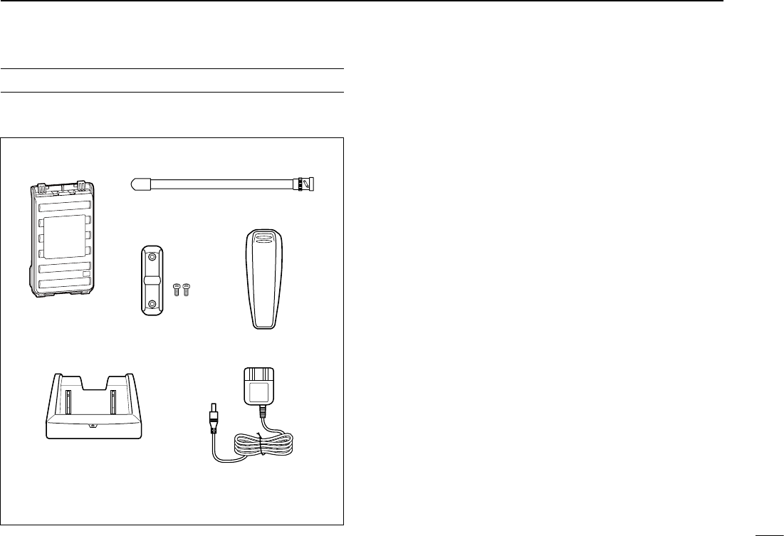
SUPPLIED ACCESSORIES
The following accessories are supplied with the transceiver.
AntennaBattery pack*
Belt clip*
Jack cover
(with screws)
Battery charger* AC adapter*
* Not supplied, or the shape is different,
depending on the version.

v
TABLE OF CONTENTS
FOREWORD ..................................................................................... i
FEATURES ........................................................................................ i
EXPLICIT DEFINITIONS ................................................................... i
IMPORTANT ...................................................................................... i
PRECAUTIONS ............................................................................ii–iii
FCC INFORMATION ....................................................................... iii
SUPPLIED ACCESSORIES ............................................................ iv
TABLE OF CONTENTS ............................................................... v–vi
1 ACCESSORIES ...........................................................1–2
■ Antenna ...................................................................................1
■ Belt clip ....................................................................................1
■ Battery pack/case ....................................................................2
■ Jack cover ................................................................................2
2 PANEL DESCRIPTION ................................................3–7
■■ Front, top and side panels .......................................................3
■ Function display .......................................................................6
3 BATTERY CHARGING ..............................................8–13
■ Caution
(for the BP-264 Ni-MH battery) ................................... 8
■ Caution (for the BP-265 Li-Ion battery) .................................... 9
■ Battery chargers ....................................................................11
■
Battery case (BP-263) ............................................................... 13
■ Battery information ................................................................13
4 BASIC OPERATION ................................................14–19
■ Power ON ..............................................................................14
■ Adjusting the volume level .....................................................14
■ Adjusting the squelch level ....................................................14
■ Monitor function .....................................................................14
■ Mode selection.......................................................................15
■ Operating mode selection ......................................................16
■ Setting a tuning step ..............................................................16
■ Setting a frequency ................................................................16
■ Receiving ...............................................................................17
■ Transmitting ............................................................................17
■ Key lock function ....................................................................18
■ [VOL] function assignment .....................................................18
■ Weather channel operation (U.S.A. version only) ..................19
5 REPEATER AND DUPLEX OPERATION ...............20–23
■ Repeater operation ................................................................20
■ Duplex operation ....................................................................21
■ Subaudible tones ...................................................................22
■ Lockout function .....................................................................23
■ Auto repeater function (U.S.A. version only) .........................23
6 MEMORY/CALL OPERATION ................................24–28
■ General description................................................................24
■ Selecting a memory channel .................................................24
■ Selecting the Call channel .....................................................24
■
Channel programming ...........................................................25
■ Copying memory/Call contents .............................................. 26
■
Clearing memory contents .............................................................27
■ Display type ........................................................................... 27
■
Programming a channel name .................................................28

vi
7 SCAN OPERATION .................................................29–31
■ Scan types .............................................................................29
■■ Programmed scan ................................................................29
■ Memory Scan ........................................................................30
■ Setting skip channels .............................................................30
■ Scan resume setting ..............................................................30
■ Priority watch .........................................................................31
8 TONE SQUELCH AND POCKET BEEP .................32–34
■
Tone/DTCS squelch and pocket beep ....................................32
■ Tone scan...............................................................................34
9 DTMF MEMORY ......................................................35–37
■
Programming a DTMF code sequence ..................................35
■
Transmitting a DTMF code sequence ....................................36
■ Confirming a DTMF memory ................................................. 37
■ Setting DTMF transfer speed .................................................37
10 SET MODES ............................................................38–47
■ Set mode programming .........................................................38
■ Set mode items ......................................................................39
■
Initial Set mode programming................................................... 43
■ Initial Set mode items ............................................................44
11 CLONING ......................................................................48
■ Cloning operation ...................................................................48
12 RESETTING ..................................................................49
■ Resetting................................................................................49
13 TROUBLE SHOOTINGTROUBLE SHOOTING ..................................................50
14
OPTIONS .................................................................51–53
■ VOX function ..........................................................................52
15 SPECIFICATIONS .........................................................54
16
CE ............................................................................55–56
TABLE OF CONTENTS 1
2
3
4
5
6
7
8
9
10
11
12
13
14
15
16
17
18
19
11
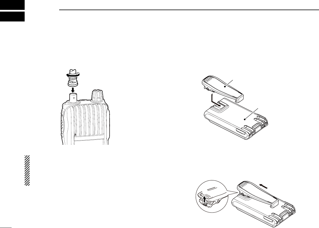
■ Antenna
Insert the antenna into the antenna connector and twist the
antenna to lock it in place.
CAUTION:
•
NEVER HOLD just the antenna when carrying the trans-
ceiver.
• Transmitting without an antenna will damage the trans-
ceiver.
■ Belt clip
To attach the belt clip:
➥ Slide the belt clip in the direction of the arrow until the belt
clip locks in place, and makes a ‘click’ sound.
To detach the belt clip:
q Remove the battery pack/case from the transceiver, if it is
attached. (p. 2).
w Lift the tab up (q), and slide the belt clip in the direction
of the arrow (w).
ACCESSORIES
1
Belt clip
Battery pack/case
q
w
2
1
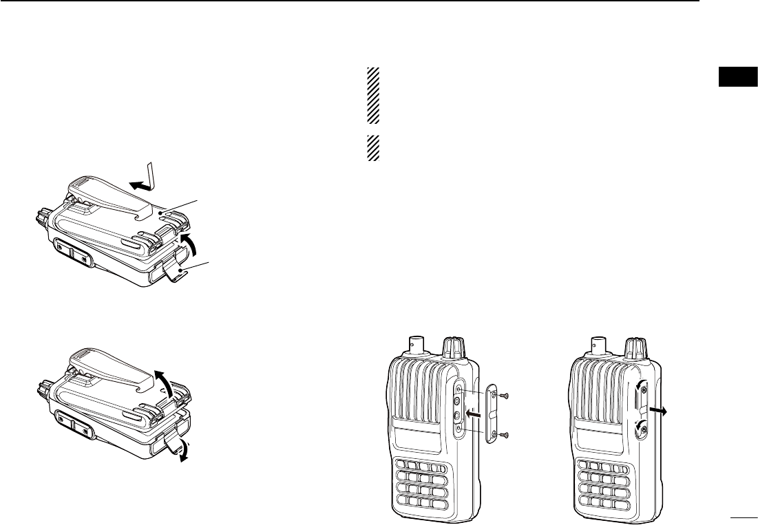
■ Battery pack/case
To attach the battery pack/case:
q Fit the battery pack/case in the direction of the arrow (q),
then close.
w Hook the latch until it makes a ‘click’ sound (w).
To remove the battery pack/case:
➥ Unhook the latch (e), and lift up the battery pack/case in
the direction of the arrow (r).
NEVER remove or attach the battery pack/case when the
transceiver is wet or soiled. This may result in water or
dust getting into the transceiver/battery pack/case, and
may result in them being damaged.
NOTE: Keep the battery terminals clean. It’s a good idea
to clean the battery terminals once a week.
■ Jack cover
Attach the jack cover when optional equipment is not used.
1
ACCESSORIES
2
3
4
5
6
7
8
9
10
11
12
13
14
15
16
17
18
19
To attach the jack cover
q Attach the jack cover to
the [SP MIC] jack.
w Tighten the screws.
To detach the jack cover
e Remove the screws with a
phillips screwdriver.
r Detach the jack cover to
connect optional equip-
ment.
w
q
Latch
Battery pack/case
e
r
r
w
w
q
e
e
Be careful! The latch is tightly locked, so use caution when
releasing it. DO NOT use your finger nail. Use the edge of a
coin or screwdriver tip to carefully release it.
3
PANEL DESCRIPTION
2
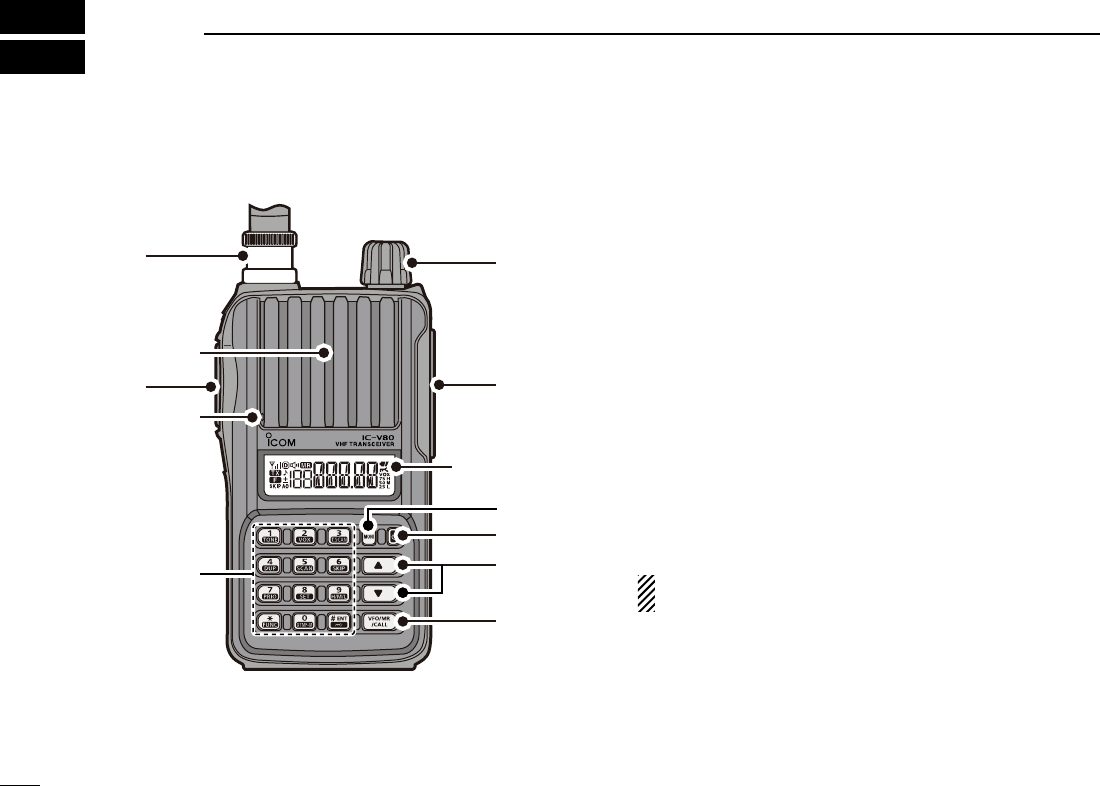
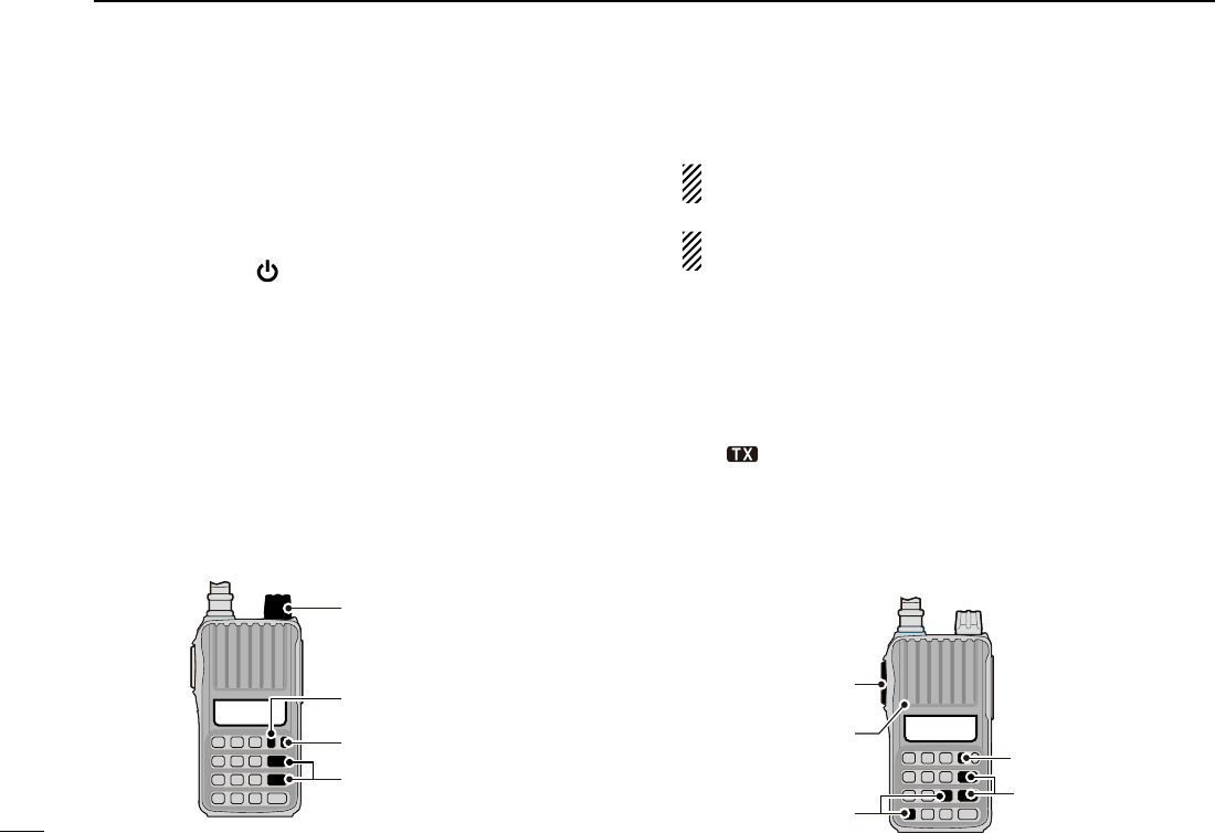
■ Front, top and side panels
q PTT SWITCH [PTT]
➥ Push and hold to transmit, release to receive. (p. 17)
For IC-V80E only
➥ Push briefly, then push and hold to transmit a 1750 Hz
tone burst signal. (p. 22)
w ANTENNA CONNECTOR
Connect the antenna here. (p. 1)
e CONTROL DIAL [VOL]
➥ Adjust the volume level. (p. 14)
➥ During the Set mode, or Initial Set mode, rotate to se-
lect a desired option or value. (pp. 38, 43)
r EXTERNAL SPEAKER/MICROPHONE JACKS [SP MIC]
Used to connect an optional speaker-microphone, plug
adapter cable or cloning cable. The internal microphone
and speaker will not function when an option is con-
nected. See page 51 for a list of available options.
Be sure to turn power OFF before connecting/discon-
necting optional equipment to/from the [SP/MIC] jack.
t MONITOR KEY [MONI]
➥ Push and hold to open the squelch temporarily to mon-
itor the operating frequency. (p. 14)
➥ While pushing and holding this key, push [] or [] to
adjust the squelch level. (p. 14)
➥ Enters or sends the DTMF code ‘A.’ (pp. 35, 36)
q
we
r
t
y
u
i
Function
display (p. 6)
Keypad (p. 4)
Microphone
Speaker
4
2
y POWER KEY [ ]
Push and hold for 1 sec. to turn the transceiver power ON
or OFF. (p. 14)
u UP/DOWN KEYS []/[]
➥ Push to change the operating frequency. (p. 16)
➥ During memory mode operation, push to select a
memory channel. (p. 24)
➥ While scanning, push to change the scanning direction.
(pp. 29, 30, 31, 34)
➥ While pushing and holding [MONI], push to set the
squelch level. (p. 14)
➥ During the Set mode, or Initial Set mode, push to se-
lect a desired setting item. (pp. 38, 43)
➥ [] enters or sends the DTMF code ‘B.’ (pp. 35, 36)
➥ [] enters or sends the DTMF code ‘C.’ (pp. 35, 36)
i VFO/MEMORY/CALL KEY [VFO/MR/CALL]
➥ Push to select the VFO mode, memory mode, a Call
channel and a weather channel*, in sequence. (p. 15)
*Only the U.S.A. version transceivers.
➥ After pushing [FUNC](M), push to enter the memory
programming mode.
➥ After pushing [FUNC](M), push and hold for 1 sec. to
transfer a channel contents to a memory channel, or to
the VFO mode. (p. 26)
➥ Enters or sends the DTMF code ‘D.’ (pp. 35, 36)
The functions of [VOL] and []/[] can be exchanged.
See page 18 for details.
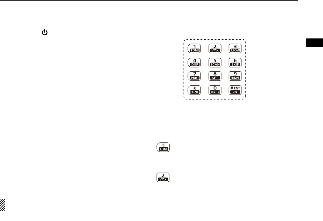
D KEYPAD
➥ Push to input numbers for frequency input and memory
channel selection.
➥ Push to enter or send the DTMF code. (pp. 35, 36)
➥ To activate the second function of a key, first push
[FUNC](M), and then push the key.
[1] • [ TONE](1)
➥ Numeric input and DTMF code: ‘1’
➥ After pushing [FUNC](M), selects the Tone func-
tion. (p. 33)
[2] • [VOX](2)
➥ Numeric input and DTMF code: ‘2’
➥ After pushing [FUNC](M), turns the VOX function
ON or OFF*. (p. 52)
* Only when an optional headset and plug adapter are
connected.
2
PANEL DESCRIPTION
1
3
4
5
6
7
8
9
10
11
12
13
14
15
16
17
18
19
5
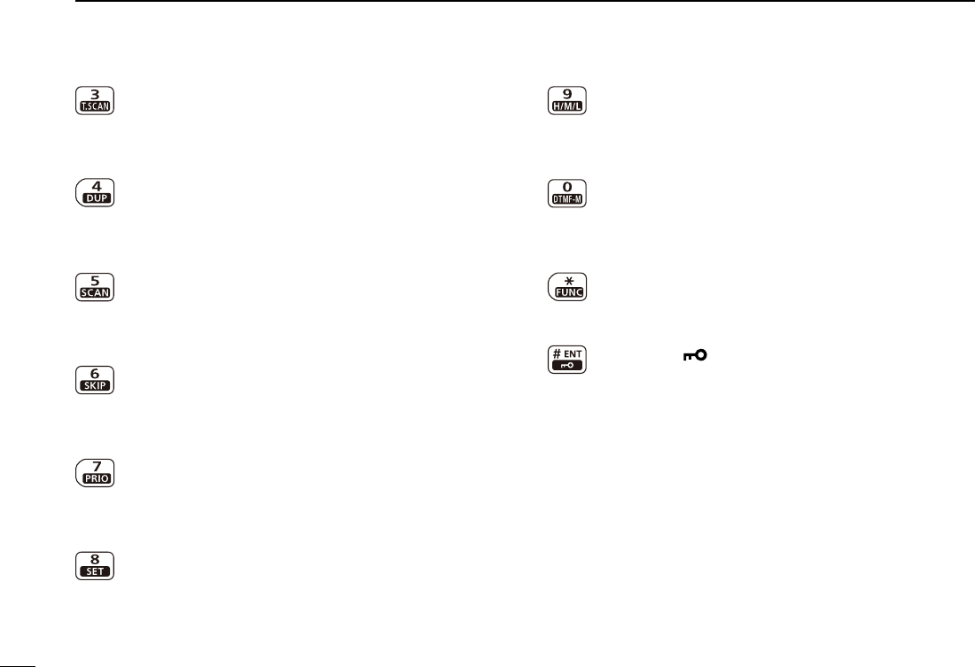
[3] • [T.SCAN](3)
➥ Numeric input and DTMF code: ‘3’
➥ After pushing [FUNC](M), starts a tone scan.
(p. 34)
[4] • [DUP](4)
➥ Numeric input and DTMF code: ‘4’
➥ After pushing [FUNC](M), selects minus duplex,
plus duplex, or simplex operation. (p. 21)
[5] • [SCAN](5)
➥ Numeric input and DTMF code: ‘5’
➥ After pushing [FUNC](M), starts a scan. (pp. 29,
30)
[6] • [SKIP](6)
➥ Numeric input and DTMF code: ‘6’
➥ After pushing [FUNC](M), sets or cancels the
skip setting. (p. 30)
[7] • [PRIO](7)
➥ Numeric input and DTMF code: ‘7’
➥ After pushing [FUNC](M), starts a priority watch.
(p. 31)
[8] • [SET](8)
➥ Numeric input and DTMF code: ‘8’
➥ After pushing [FUNC](M), enters the Set mode.
(p. 38)
[9] • [H/M/L](9)
➥ Numeric input and DTMF code: ‘9’
➥ After pushing [FUNC](M), selects the output
power between high, middle and low. (p. 17)
[0] • [DTMF-M](0)
➥ Numeric input and DTMF code: ‘0’
➥ After pushing [FUNC](M), enters the DTMF
memory mode. (p. 35)
[M] • [FUNC](M)
➥ DTMF code: ‘M (indication: E)’
➥ Push to access the second function of other keys.
[# ENT] • [ ](# ENT)
➥ DTMF code: ‘# (indication: F)’
➥ After entering a frequency, stores the frequency.
(p. 16)
➥ Push to exit the Set mode or Initial Set mode.
(pp. 38, 43)
➥
After pushing [FUNC](M), push and hold for 1 sec.
to turn the key lock function ON or OFF (p. 18)
2PANEL DESCRIPTION
6
2
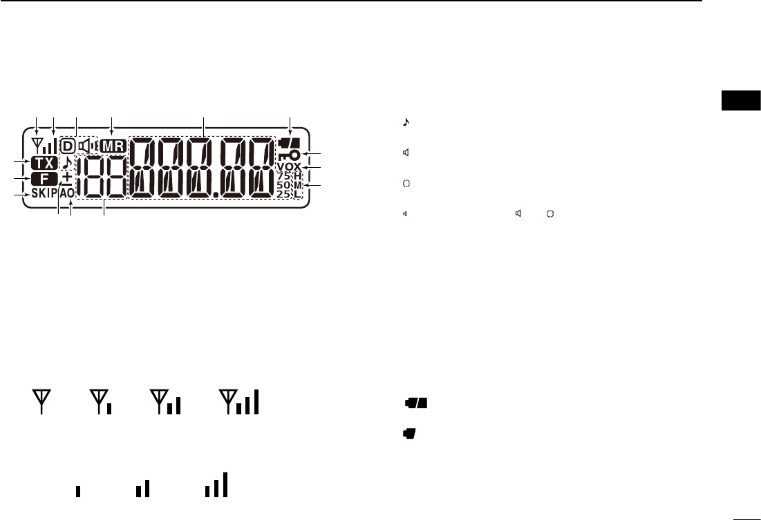
■ Function display
q BUSY INDICATOR
➥ Appears when a signal is being received, or the
squelch is open.
➥ Blinks while the monitor function is ON. (p. 14)
w SIGNAL INDICATOR
➥ Shows the strength of the received signal. (p. 17)
➥ While transmitting, shows the output power level.
(p. 17)
e TONE INDICATOR
➥ “ ” appears while the repeater tone encoder is ON.
(p. 20)
➥ “ ” appears while the tone squelch function is ON.
(p. 33)
➥ “
D
” appears while the DTCS squelch function is ON.
(p. 33)
➥ “ ” appears with the “ ” or “
D
” indicator while the pocket
beep function (with CTCSS or DTCS) is ON. (p. 33)
r MEMORY INDICATOR
Appears when the memory mode is selected. (pp. 15, 24)
t FREQUENCY READOUT
➥ Displays the operating frequency, memory channel,
Set modes contents and a variety of other information.
• The decimal point blinks during scan.
➥ During memory mode operation, the programmed
memory name is displayed.
y BATTERY INDICATOR (p. 13)
➥ “ ” (battery indicators) appear when the battery
pack/case is attached.
➥ “ ” appears when the battery pack must be changed,
or batteries must be replaced.
2
PANEL DESCRIPTION
Weak RX Signal level Strong
Low Middle High
u
i
o
q w e r y
t
!5
!4
!3
!1!2 !0
1
3
4
5
6
7
8
9
10
11
12
13
14
15
16
17
18
19

7
u KEY LOCK INDICATOR
Appears when the key lock function is ON. (p. 18)
i VOX INDICATOR
Appears when the VOX function is ON. (p. 52)
o POWER INDICATOR (p. 17)
➥ “ H” appears when high power is selected.
➥ “ M” appears when middle power is selected.
➥ “ L” appears when low power is selected.
!0 MEMORY CHANNEL NUMBER INDICATOR
➥ Displays the selected memory channel number. (p. 24)
➥ “C” appears when the Call channel is selected. (p. 24)
!1 AUTO POWER OFF INDICATOR
Displays when the Auto Power OFF function is ON. (p. 44)
!2 DUPLEX INDICATOR (p. 21)
➥ “+” appears when plus duplex is selected.
➥ “–” appears when minus duplex is selected.
!3 SKIP INDICATOR
Appears when the selected memory channel is set as a
skip channel. (p. 30)
!4 FUNCTION INDICATOR
Appears when the second function can be accessed.
!5 TRANSMIT INDICATOR
Appears while transmitting. (p. 17)
2PANEL DESCRIPTION

8
2
3
3
BATTERY CHARGING
■ Caution
(for the BP-264 Ni-MH battery)
R DANGER! NEVER short terminals (or charging terminals)
of the battery pack. Also, current may flow into nearby metal
objects such as a necklace, so be careful when placing bat-
tery packs (or the transceiver) in handbags, etc.
Simply carrying with or placing near metal objects such as
a necklace, etc. may cause shorting. This may damage not
only the battery pack, but also the transceiver.
R DANGER! NEVER incinerate used battery packs. Internal
battery gas may cause an explosion.
R DANGER! NEVER immerse the battery pack in water.
If the battery pack becomes wet, be sure to wipe it dry BE-
FORE attaching it to the transceiver.
CAUTION: Always use the battery within the specified tem-
perature range, –5˚C to +60˚C (+23˚F to +140˚F). Using the
battery out of its specified temperature range will reduce the
battery’s performance and battery life.
CAUTION: Shorter battery life could occur if the battery is
left completely discharged, or in an excessive temperature
environment (above +55˚C; +131˚F) for an extended period
of time. If the battery must be left unused for a long time,
it must be detached from the radio after charging. Keep it
safely in a cool dry place at the following temperature range:
–20˚C to +45˚C (–4˚F to +113˚F) (up to a month)
–20˚C to +35˚C (–4˚F to +95˚F) (up to six months)
–20˚C to +25˚C (–4˚F to +77˚F) (up to a year*)
* We recommend charging the battery pack every 6 months.
Clean the battery terminals to avoid rust or misscontact.
Keep battery terminals clean. It’s a good idea to clean bat-
tery terminals once a week.
If your Ni-MH battery pack seems to have no capacity, even
after being charged, completely discharge it by leaving the
power ON overnight. Then, fully charge the battery pack again.
If the battery pack still does not retain a charge (or only very lit-
tle charge), a new battery pack must be purchased. (p. 51)
Prior to using the transceiver for the first time, the battery
pack must be fully charged for optimum life and operation.
• Recommended temperature range for charging:
between +10°C and +40°C (rapid charge: with BC-191) or
between 0°C and +45°C (regular charge: with BC-192)
• Use the supplied charger or optional charger (BC-191 for
rapid charging, BC-192 for regular charging) only. NEVER
use other manufacturers’ chargers.
The battery pack contains a rechargeble battery.
Charge the battery pack before first operating the trans-
ceiver, or when the battery pack becomes exhausted.
If you want to prolong the battery life, the following points
should be observed:
• Avoid over charging. The charging time period should be
less than 48 hours.
• Use the battery pack until it becomes almost completely
exhausted, under normal conditions. We recommend bat-
tery charging after transmitting becomes impossible.
1
4
5
6
7
8
9
10
11
12
13
14
15
16
17
18
19

9
■ Caution (for the BP-265 Li-Ion battery)
R DANGER! Use and charge only specified Icom battery
packs with Icom radios or Icom chargers. Only Icom battery
packs are tested and approved for use with Icom radios or
charged with Icom chargers. Using third-party or counterfeit
battery packs or chargers may cause smoke, fire, or cause
the battery to burst.
D Battery caution
R DANGER! DO NOT hammer or otherwise impact the bat-
tery. Do not use the battery if it has been severely impacted
or dropped, or if the battery has been subjected to heavy
pressure. Battery damage may not be visible on the outside
of the case. Even if the surface of the battery does not show
cracks or any other damage, the cells inside the battery may
rupture or catch fire.
R DANGER! NEVER use or leave battery pack in areas
with temperatures above +60˚C (+140˚F). High tempera-
ture buildup in the battery, such as could occur near fires
or stoves, inside a sun heated car, or in direct sunlight may
cause the battery to rupture or catch fire. Excessive temper-
atures may also degrade battery performance or shorten
battery life.
R DANGER! DO NOT expose the battery to rain, snow, sea-
water, or any other liquids. Do not charge or use a wet battery.
If the battery gets wet, be sure to wipe it dry before using.
R DANGER! NEVER incinerate a used battery pack since
internal battery gas may cause it to rupture, or may cause
an explosion.
R DANGER! NEVER solder the battery terminals, or
NEVER modify the battery pack. This may cause heat gener-
ation, and the battery may burst, emit smoke or catch fire.
R DANGER! Use the battery only with the transceiver for
which it is specified. Never use a battery with any other
equipment, or for any purpose that is not specified in this in-
struction manual.
R DANGER! If fluid from inside the battery gets in your
eyes, blindness can result. Rinse your eyes with clean water,
without rubbing them, and see a doctor immediately.
R
WARNING! Immediately stop using the battery if it emits
an abnormal odor, heats up, or is discolored or deformed. If
any of these conditions occur, contact your Icom dealer or
distributor.
R
WARNING! Immediately wash, using clean water, any
part of the body that comes into contact with fluid from in-
side the battery.
3BATTERY CHARGING
Misuse of Li-Ion batteries may result in the following haz-
ards: smoke, fire, or the battery may rupture. Misuse can
also cause damage to the battery or degradation of battery
performance.

10
3
3
BATTERY CHARGING
R
WARNING! NEVER put the battery in a microwave oven,
high-pressure container, or in an induction heating cooker.
This could cause a fire, overheating, or cause the battery to
rupture.
CAUTION: Always use the battery within the specified tem-
perature range, –20˚C to +60˚C (–4˚F to +140˚F). Using the
battery out of its specified temperature range will reduce the
battery’s performance and battery life.
CAUTION: Shorter battery life could occur if the battery is
left fully charged, completely discharged, or in an excessive
temperature environment (above +50˚C; +122˚F) for an ex-
tended period of time. If the battery must be left unused for a
long time, it must be detached from the radio after discharg-
ing. You may use the battery until the battery indicator shows
half-capacity, and then keep it safely in a cool dry place at
the following temperature range:
–20˚C to +50˚C (–4˚F to +122˚F) (up to a month)
–20˚C to +35˚C (–4˚F to +95˚F) (up to three months)
–20˚C to +20˚C (–4˚F to +68˚F) (up to a year)
D Charging caution
R DANGER! NEVER charge the battery pack in areas with
extremely high temperatures, such as near fires or stoves,
inside a sun-heated vehicle, or in direct sunlight. In such en-
vironments, the safety/protection circuit in the battery will ac-
tivate, causing the battery to stop charging.
R
WARNING! DO NOT charge or leave the battery in the
battery charger beyond the specified time for charging. If the
battery is not completely charged by the specified time, stop
charging and remove the battery from the battery charger.
Continuing to charge the battery beyond the specified time
limit may cause a fire, overheating, or the battery may rup-
ture.
R
WARNING! NEVER insert the transceiver (battery at-
tached to the transceiver) into the charger if it is wet or
soiled. This could corrode the battery charger terminals or
damage the charger. The charger is not waterproof.
CAUTION: DO NOT charge the battery outside of the spec-
ified temperature range: BC-193 (+10˚C to +40˚C; +50˚F
to +104˚F). Icom recommends charging the battery at +20˚C
(+68˚F). The battery may heat up or rupture if charged out of
the specified temperature range. Additionally, battery perfor-
mance or battery life may be reduced.
The supplied battery pack, charger, and AC adapter dif-
fer, or no supplied depending on the version.
Prior to using the transceiver for the first time, the battery
pack must be fully charged for optimum life and operation.
1
2
4
5
6
7
8
9
10
11
12
13
14
15
16
17
18
19
11
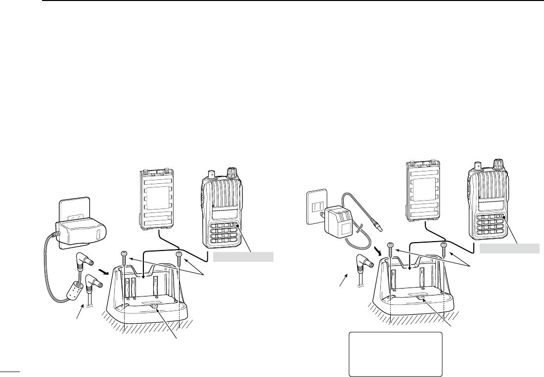
■ Battery chargers
D
Using the BC-191 to rapid charge the BP-264
The BC-191 provides rapid charging of only the BP-264 Ni-MH
battery pack. Never use it to charge any other battery pack.
Charging time: Approx. 2 hours
The following item is additionally required:
• An AC adapter (not supplied with some versions) or the OPC-515L
or CP-23L DC power cable.
D Using the BC-192 to regular charge the BP-264
The BC-192 provides regular charging of only the BP-264
Ni-MH battery pack. Never use it to charge any other battery
pack.
Charging time (with the 147S): Approx. 16 hours
The following item is additionally required:
• An AC adapter (not supplied with some versions) or the OPC-515L
DC power cable.
3BATTERY CHARGING
The optional OPC-
515L (for DC power
source) can be
used instead of the
AC adapter.
Charge indicator
• Lights green while charging.
NOTE:
The charge indicator will not
go out even after a battery
pack is fully charged.
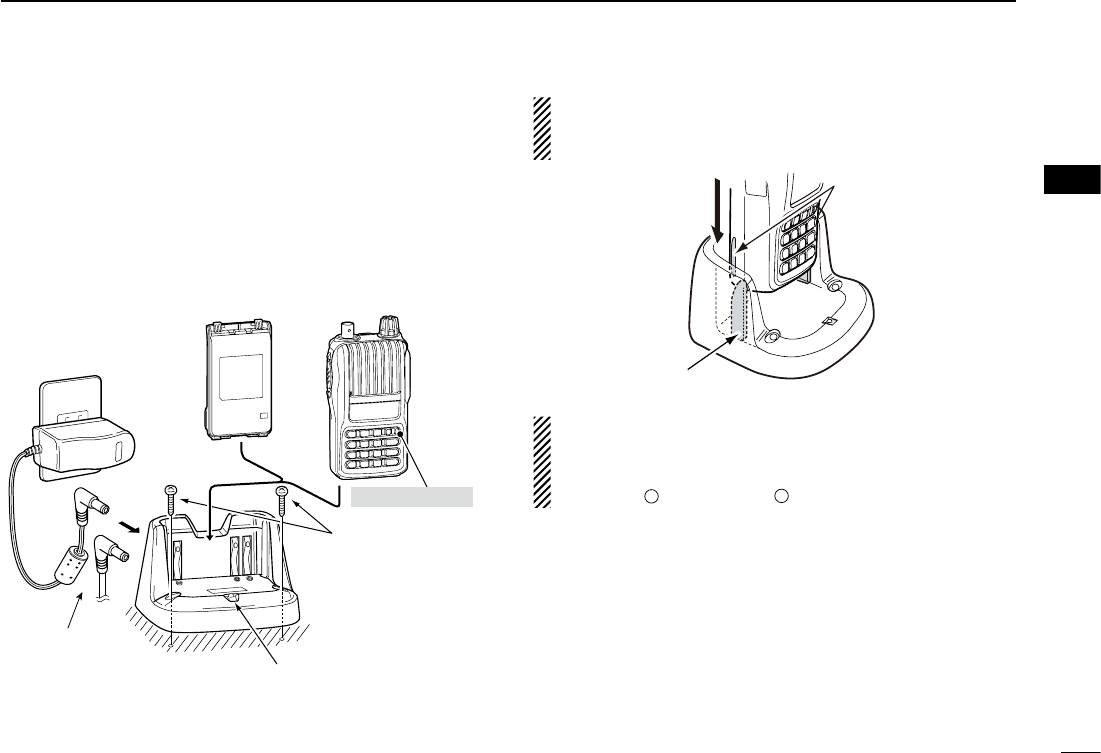
AC adapter
(A different type, or no AC
adapter is supplied, de-
pending on the version.)
Transceiver
Turn power OFF
Battery pack
Screws*
(Self tapping screw:
M3.5 × at least 30 mm)
*Purchase separately.
Using screws is
recommended to
secure the charger.
Charging time period differs
depending on the input voltage.
12 V : Approx. 36 hours
13.8 V : Approx. 21 hours
16 V : Approx. 16 hours
The optional OPC-
515L (for DC power
source) or CP-23L
(for 12 V cigarette
lighter socket) can
be used instead of
the AC adapter.
Charge indicator
• Lights orange : While charging
• Lights green :
Charging is completed.
AC adapter
(A different type, or no AC
adapter is supplied, de-
pending on the version.)
Transceiver
Turn power OFF
Battery pack
Screws*
(Self tapping screw:
M3.5 × at least 30 mm)
*Purchase separately.
Using screws is
recommended to
secure the charger.
12
3
3
BATTERY CHARGING
D
Using the BC-193 to rapid charge the BP-265
The BC-193 provides rapid charging of only the BP-265 Li-
Ion battery pack. Never use it to charge any other battery
pack.
Charging time: Approx. 2.5 hours
The following item is additionally required:
• An AC adapter (not supplied with some versions) or the OPC-515L
or CP-23L DC power cable.
IMPORTANT: Battery charging caution
Ensure the tabs on the battery pack are correctly aligned
with the guide rails inside the charger.
CAUTION: When using the OPC-515L DC power cable
NEVER connect the OPC-515L to a power source using
reverse polarity. This will ruin the battery charger.
White line:
+
Black line:
–
The optional OPC-
515L (for DC power
source) or CP-23L
(for 12 V cigarette
lighter socket) can
be used instead of
the AC adapter.
AC adapter
(A different type, or no AC
adapter is supplied, de-
pending on the version.)
Transceiver
Turn power OFF
Battery pack
Screws*
(Self tapping screw:
M3.5 × at least 30 mm)
*Purchase separately.
Using screws is
recommended to
secure the charger.
Charge indicator
• Lights orange : While charging
• Lights green :
Charging is completed.
Guide rail
Tabs
1
2
4
5
6
7
8
9
10
11
12
13
14
15
16
17
18
19
13
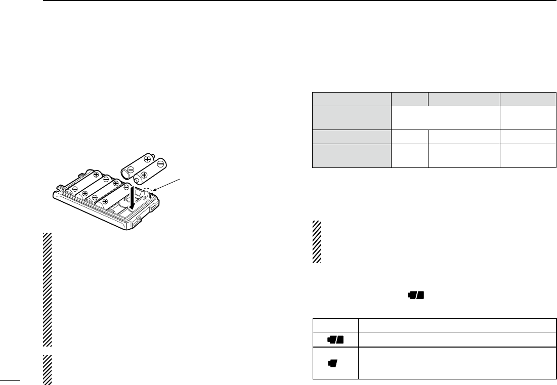
■ Battery case (BP-263)
When using the battery case (BP-263), install 6 × AA (LR6)
size alkaline batteries, as described below.
q Remove the battery case if it is attached. (p. 2)
w Install 6 × AA (LR6) size alkaline batteries.
• Install only alkaline batteries.
• Be sure to observe the correct polarity.
e Attach the battery case. (p. 2)
CAUTION:
• When installing batteries, make sure they are all the same
brand, type and capacity. Also, do not mix new and old bat-
teries together.
• Keep battery terminals clean. It’s a good idea to clean bat-
tery terminals once a week.
• Never incinerate used battery cells since the internal bat-
tery gas may cause them to rupture.
•
Never expose a detached battery case to water. If the battery
case gets wet, be sure to wipe it dry before using it.
• Never use batteries whose insulated covering is damaged.
NOTE: When the battery case is attached, the battery
protection function must be turned OFF in the Initial Set
mode (p. 47).
■ Battery information
D Battery life
Even when the transceiver power is OFF, a small current
still flows in the transceiver.
Remove the battery pack/case
when it won’t be used for a long time.
Otherwise, the battery
pack or the batteries in the case will become exhausted.
D Battery indication
The battery indicator, “ ,” appears when a battery pack/
case is attached to the transceiver.
3BATTERY CHARGING
Battery pack/case
Voltage Capacity Battery life*1
BP-263 Battery case for
AA (LR6) × 6 alkaline —*2
BP-264 7.2 V 1400 mAh 13 hrs.
BP-265 7.4 V 1900 mAh (min.)
2000 mAh (typ.) 19 hrs.
*1
When the power save function is set to “P–S.At,” and the operating
time is calculated under the following conditions;
TX : RX : standby = 5 : 5 : 90
*2 The average operating life depends on the alkaline cells used.
Indicator Battery condition
The battery has ample capacity.
The battery is nearing exhaustion.
Charging the battery pack, or replacing the batteries
in the case is necessary.
Be careful! The negative
terminals of the battery case
protrude from the body, so
pay attention not to injure
your fingers when inserting
the batteries.
14
3
4
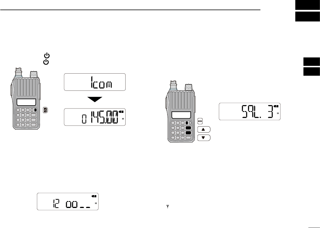
■ Power ON
➥ Push and hold [ ] for 1 sec. to turn the power ON.
• Push and hold [ ] for 1 sec. to turn the power OFF.
■ Adjusting the volume level
➥ Rotate [VOL] to
adjust the volume level.
• If the squelch is closed, push and hold [MONI] while adjusting the
volume level.
• The display shows the volume level while adjusting.
■ Adjusting the squelch level
➥ While pushing and holding [MONI], push [] or [] sev-
eral times
to adjust the squelch level.
• “SqL 1” is loose squelch (for weak signals) and “SqL10” is tight
squelch (for strong signals). “SqL 0” is open squelch.
■ Monitor function
This function is used to listen to weak signals or to open
the squelch manually. You can use it without disturbing the
squelch setting, even when mute functions such as the tone
squelch are in use.
➥ Push and hold [MONI] to monitor the operating frequency.
• “ ” blinks while the monitor function is ON.
4
BASIC OPERATION
1
2
5
6
7
8
9
10
11
12
13
14
15
16
17
18
19
15
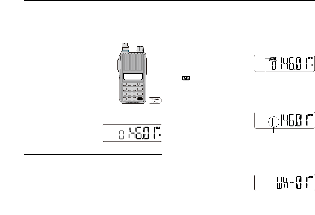
■ Mode selection
➥ Pus h [VFO/MR/CALL] several
times to select the VFO mode,
memory mode, Call channel mode
and weather channel mode*, in se-
quence.
*For only the U.S.A. version transceivers.
D VFO mode
The VFO mode is used to set
the operating frequency.
What is VFO?
VFO is an abbreviation of Variable Frequency Oscillator. Fre-
quencies for both transmitting and receiving are generated
and controlled by the VFO.
D Memory mode
The memory mode is used for
operating on memory channels,
which store programmed fre-
quencies.
• “
” appears when the memory
mode is selected.
D Call channel mode
The Call channel is used for
quick recall of the most often-
used frequency.
• “C” appears instead of the memory
channel number when the Call
channel mode is selected.
D Weather channel mode*
There are 10 weather channels
for monitoring weather broad-
casts from NOAA (National
Oceanic and Atmospheric Ad-
ministration).
* Only for the U.S.A. version trans-
ceivers.
• Memory mode display
Appears
• VFO mode display
Appears
• Call channel mode display
• Weather channel mode
display
4BASIC OPERATION
16
4
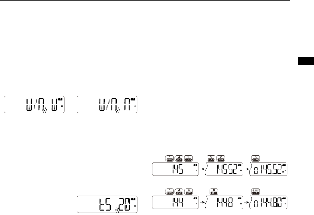
■ Operating mode selection
Operating modes are determined by the modulation of the
radio signals.
The transceiver has the FM and FM-N modes
.
The mode
selection is independently stored for each memory
channel
.
q Push [FUNC](M) then [SET](8) to enter the Set mode.
w Push [] or [] to select the operating mode item. (W/n)
e Rotate [VOL] to set the operating mode to FM or FM-N.
r Push [# ENT] to exit the Set mode.
■ Setting a tuning step
The transceiver has 8 tuning step options;
• 5 kHz • 10 kHz • 12.5 kHz • 15 kHz • 20 kHz
• 25 kHz • 30 kHz • 50 kHz
The tuning step can be selected in the Set mode.
q
Push [FUNC](M), and then [SET](8) to enter the Set mode.
w Push [] or [] to select the tuning step item. (tS)
e Rotate [VOL] to select the
desired tuning step.
r Push [# ENT] to exit the Set
mode.
■ Setting a frequency
D Using [] or []
q Push [VFO/MR/CALL] several times to select the VFO
mode.
w Push [] or [] to select the desired frequency.
• The frequency changes according to the preset tuning steps.
See the previous topic to set the tuning step.
D Using the keypad
q Push [VFO/MR/CALL] several times to select the VFO
mode.
w To enter the desired frequency, enter 6 digits, starting
from 100 MHz digit.
• Entering two or three* to five digits, and then pushing [# ENT],
also sets the frequency. (*Depending on the version)
• If a frequency outside the frequency range is entered, the previ-
ously displayed frequency is automatically recalled.
• Example 1— entering 145.525 MHz
Push
• Example 2— entering 144.800 MHz
Push
20 kHz tuning step
FM mode FM-N mode
4
BASIC OPERATION
1
2
3
5
6
7
8
9
10
11
12
13
14
15
16
17
18
19
17
■ Receiving
Make sure the BP-264 or BP-265 battery pack is fully
charged, or the BP-263 battery case has brand new alkaline
batteries (pp. 11–13).
q Push and hold [ ] for 1 sec. to turn power ON.
w Rotate [VOL] to set the desired volume level. (p. 14)
• The volume level is displayed on the LCD while adjusting.
e Set the receive frequency. (p. 16)
r Set the squelch level. (p. 14)
• While pushing and holding [MONI], push [] or [].
• The squelch level is displayed on the LCD while setting.
• “SqL 1” is loose squelch (for weak signals) and “SqL10” is tight
squelch (for strong signals). “SqL 0” is open squelch.
• Push and hold [MONI] to open the squelch manually.
t When a signal is received:
• The squelch is opened and the audio is heard.
• The signal indicator shows the relative signal strength level.
■ Transmitting
CAUTION: Transmitting without an antenna will damage
the transceiver.
NOTE: To prevent interference, push and hold [MONI] to
listen on the frequency before transmitting.
q
Set the operating frequency. (p. 16)
w
Push [FUNC](M), and then push [H/M/L](9) to select the
output power between High (5.5 W), Mid (2.5 W) and Low
(0.5 W).
• “ H,” “M,” or “ L” appears according to the selected output power.
e Push and hold [PTT] to transmit.
• “ ” appears while transmitting.
• The signal indicator shows the output power level.
r Speak into the microphone using your normal voice level.
• DO NOT hold the transceiver too close to your mouth or speak
too loudly. This may distort your speech.
t Release [PTT] to return to receive.
4BASIC OPERATION
w Adjust the volume level.
r
For the squelch level setting.
(Push to monitor)
q Turn the power ON.
e Set the frequency.
r Adjust the squelch level.
Microphone
w Select the
output power.
Push to monitor.
q Set the frequency.
e Push and hold to
transmit.
t
Release to receive.
18
4
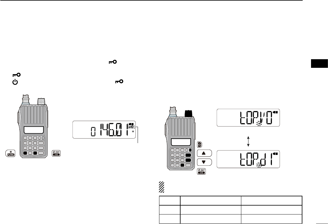
■ Key lock function
To prevent accidental frequency changes, or unnecessary
function access, use the key lock function.
➥ Push [FUNC](M), and then push and hold [ ](# ENT) for
1 sec. to turn the key lock function ON or OFF.
• “ ” appears while the key lock function is activated.
• [ ], [VOL], [MONI], [PTT] and [FUNC](M) + [ ](# ENT)
are still operable while the key lock function is ON.
■ [VOL] function assignment
[VOL] can be used as a tuning control instead of [] and
[], to suit your preference. However, when [VOL] functions
as a tuning control, [] and [] function as volume controls.
q While pushing and holding [] and [], turn the power
ON to enter the Initial Set mode.
w Push [] or [] to select the dial assignment item. (tOP)
e Rotate [VOL] to select an option.
r Push [# ENT] to exit the Initial Set mode.
[VOL] and
[]/[] function as described below, depend-
ing on the option.
Appears
[VOL]
[VOL] functions as the volume control.
[VOL] functions as the tuning control.
4
BASIC OPERATION
Option [VOL] []/[]
tOP.VO Volume control Tuning controls
tOP.di Tuning control Volume controls
1
2
3
5
6
7
8
9
10
11
12
13
14
15
16
17
18
19

19
■ Weather channel operation
There are 10 weather channels for monitoring
weather broadcasts from NOAA (National Oce-
anic and Atmospheric Administration).
D Weather channel selection
q Push [VFO/MR/CALL] several times to select the
weather channel mode.
w Push [] or [] to select a weather channel.
e Push [VFO/MR/CALL] to return to the previous frequency
or memory channel.
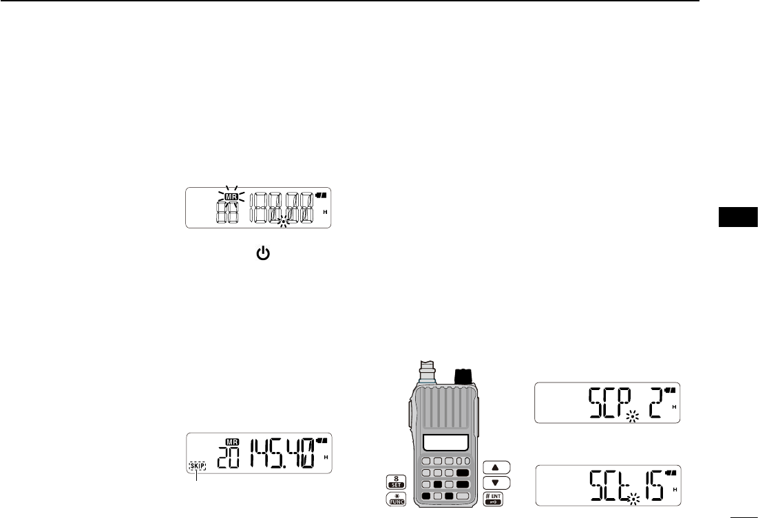
D Weather alert function
NOAA broadcast stations transmit weather alert tones be-
fore important weather announcements. When the weather
alert function is ON, the selected weather channel is moni-
tored every 5 sec. for announcements. When the alert signal
is detected, the “ALt” and the WX channel number are alter-
nately displayed, and a beep sounds until the transceiver is
operated. The previously selected (used) weather channel is
checked periodically during standby, or while scanning.
q Select a weather channel.
w Turn the weather alert function ON in the Set mode.
➥ Push [FUNC](M), and then [SET](8) to enter the Set
mode.
➥ Push [] or [] to select the weather alert item. (ALt)
➥ Rotate [VOL] to select “ON.”
➥ Push [# ENT] to exit the Set mode.
e Set the desired stand-by mode.
• Select the VFO, memory or Call channel mode.
• Scan or priority watch operation can also be selected.
r When an alert is detected, a beep sounds, and “ALt” and
the weather channel number will be alternately displayed.
t Turn the weather alert function OFF in the Set mode.
NOTE: While receiving a signal on a frequency other than
the Weather alert frequency, the receiving signal will be
interrupted momentarily approximately every 5 sec. when
the weather alert function is ON. These interruptions
cease when the weather alert function is turned OFF.
Push [FUNC](M), and then [SCAN](5) to start a weather
channel scan. Push any key except []/[], [FUNC](M)
and [MONI] to stop the scan.
U.S.A. version only
4BASIC OPERATION
• Weather channel mode
display
20
4
5
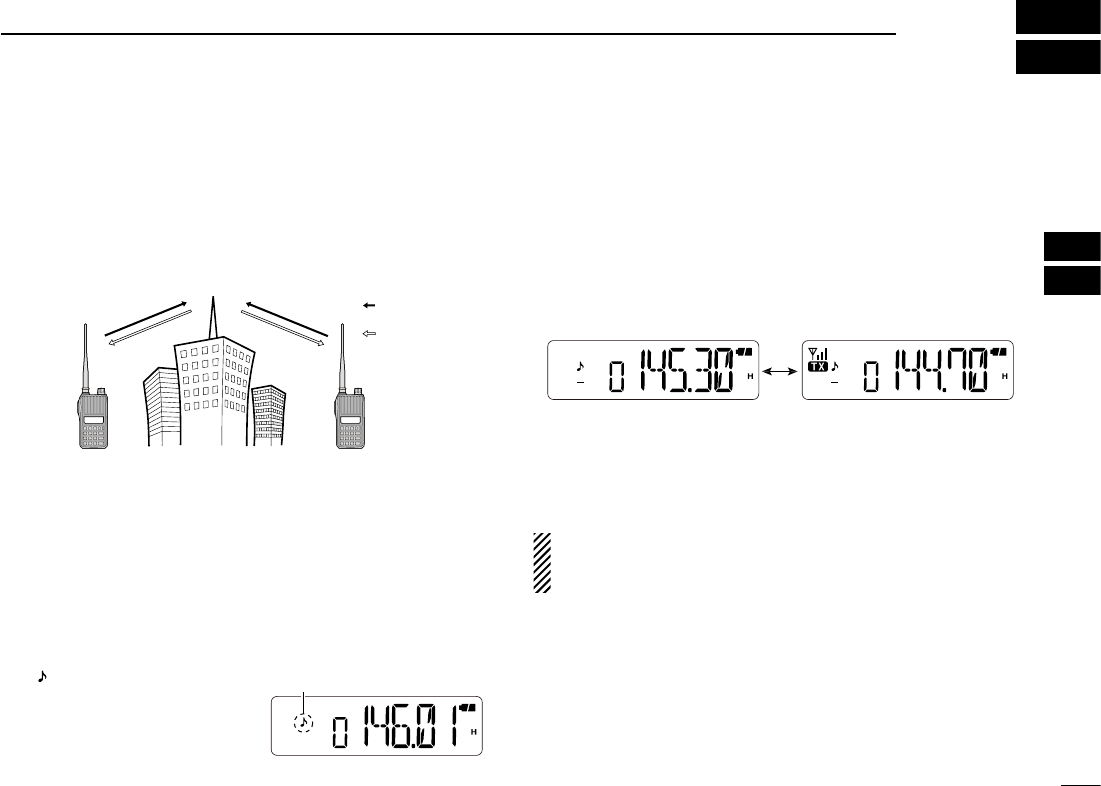
■ Repeater operation
When using a repeater, the transmit frequency is shifted
from the receive frequency by the frequency offset (p. 21).
This is called duplex operation. It is convenient to program
repeater information into memory channels (p. 25).
q Set the receive frequency (the repeater output frequency).
w Push [FUNC](M), and then [DUP](4) several times to set
the shift direction of the transmit frequency. ( “–” or “+”;
See page 21 for details.)
• When the auto repeater function is in use (U.S.A. version only),
this selection and step e are not necessary. (p. 23).
e If desired, push [FUNC](M) and then [TONE](1) several
times to activate the subaudible tone encoder.
• “ ” appears.
• Select the desired subaudible
tone frequency. (p. 22)
r Push and hold [PTT] to transmit.
• The displayed frequency automatically changes to the transmit
frequency (repeater input frequency).
•
If “OFF” appears, check the frequency offset and shift direction
(p. 21).
t Release [PTT] to receive.
y Push and hold [MONI] to check whether the other station’s
transmit signal can be directly received or not
.
• When the other station’s signal can be directly received, move
to a non-repeater frequency to use simplex. (duplex OFF)
For the U.S.A. version:
Auto repeater function uses standard values of the re-
peater tone frequency and frequency offset.
Station A Station B
Repeater
145.300 MHz
144.700 MHz 144.700 MHz
145.300 MHz
Uplink
Downlink
(transmit freq.)
(receive freq.)
5
REPEATER AND DUPLEX OPERATION
Appears
While receiving While transmitting
1
2
3
6
7
8
9
10
11
12
13
14
15
16
17
18
19
21
■ Duplex operation
D Setting the frequency offset
q Push [FUNC](M), and then [SET](8) to enter the Set mode.
w Push [] or [] to select the offset item.
• “±” blinks, and the current frequency offset appears.
e Rotate [VOL] to select the frequency offset.
• The offset is selected in the
same step as the frequency
tuning step.
• The unit of the frequency
offset is “MHz.”
r Push [# ENT] to exit the Set mode.
D Setting the duplex direction
➥ Push [FUNC](M), and then [DUP](4) to select “–” (nega-
tive offset) or “+” (positive offset).
• “–” or “+” indicates the transmit frequency is shifter up (+) or
down (–) from the receive frequency.
• Blinking “–” or “+” indicates the reverse duplex function is ON,
as described to the right.
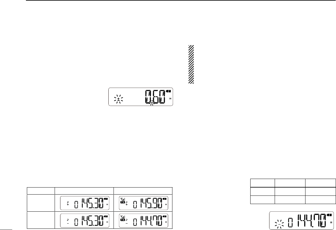
• Example— When the offset frequency is 0.6 MHz
For the U.S.A. version:
The auto repeater function has priority over the manual
duplex setting. If the transmit frequency changes after
setting, the auto repeater function may have changed the
duplex setting. Turn the auto repeater function OFF to
prevent this (p. 23).
D Reverse duplex function
When the reverse duplex function is ON, the receive and
transmit frequencies are reversed. The function can be set in
the Set mode.
q Push [FUNC](M), and then [SET](8) to enter the Set mode
.
w Push [] or [] to select the reverse duplex function item
(REV).
e Rotate [VOL] to turn the function ON or OFF.
r Push [# ENT] to exit the Set mode.
Each receive and transmit frequency is shown in the table
below, with the following configurations;
Input freq. :
145.300 MHz
Direction : – (down)
Offset : 0.6 MHz
• “–” or “+” blinks when the re-
verse duplex function is ON.
5REPEATER OPERATION
Reversed
RX freq. TX freq.
OFF
145.300 MHz 144.700 MHz
ON
144.700 MHz 145.300 MHz
0.6 MHz offset
While receiving While transmitting
Duplex
+ (up)
– (down)
22
5
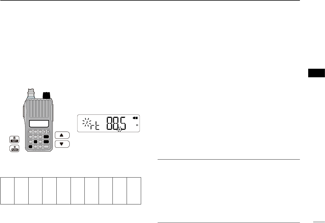
■ Subaudible tones
Some repeaters require subaudible tones to be accessed.
Subaudible tones are superimposed over your normal sig-
nal, and must be set in advance.
q Push [FUNC](M) then [SET](8) to enter the Set mode.
w Push [] or [] to select the repeater tone item. (rt)
e Rotate [VOL] to select the desired subaudible tone.
r Push [# ENT] to exit the Set mode.
• Available subaudible tone frequencies (unit: Hz)
67.0
69.3
71.9
74.4
77.0
79.7
82.5
85.4
88.5
91.5
94.8
97.4
100.0
103.5
107.2
110.9
114.8
118.8
123.0
127.3
131.8
136.5
141.3
146.2
151.4
156.7
159.8
162.2
165.5
167.9
171.3
173.8
177.3
179.9
183.5
186.2
189.9
192.8
196.6
199.5
203.5
206.5
210.7
218.1
225.7
229.1
233.6
241.8
250.3
254.1
D Tone information
Some repeaters require a different tone system to be ac-
cessed.
DTMF TONES
While pushing [PTT], push the desired DTMF keys, [0] to
[9], [MONI](A), [](B), [](C), [VFO/MR/CALL](D), [M](E),
and [# ENT](F), to transmit their assigned DTMF codes.
• The transceiver has 16 DTMF memory channels (p. 35).
1750 Hz TONE
To access some European repeaters, the transceiver must
transmit a 1750 Hz tone burst.
For IC-V80E only
Push [PTT] briefly, push and hold [PTT] again for 1 or 2 sec.
For other transceivers
While pushing [PTT], push and hold either the [] or [] for
1 or 2 sec.
See page 36 for details.
✔ CONVENIENT!
Tone scan function:
If you don’t know the subaudible tone used for a repeater,
the tone scan is convenient for detecting the tone frequency.
➥ Push [FUNC](M), and then [T.SCAN](3) to start a tone
scan.
• When the required tone frequency is detected, the scan pauses,
and the tone frequency is temporarily set.
• See page 34 for details of the tone scan function.
5
REPEATER OPERATION
88.5 Hz repeater tone
[VOL]
1
2
3
4
6
7
8
9
10
11
12
13
14
15
16
18
17
19
23
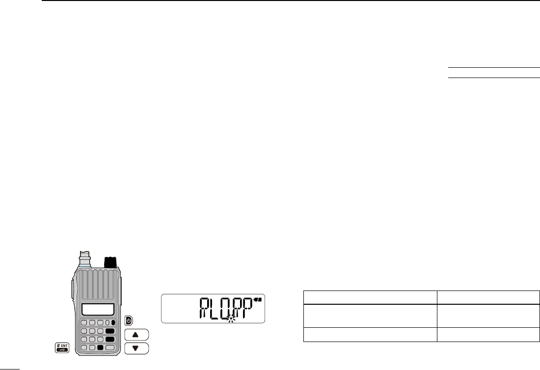
■ Lockout function
The lockout function helps prevent interference to other sta-
tions by inhibiting transmitting when the channel is busy.
The function can be set in the Initial Set mode.
q While pushing and holding [] and [], turn the power
ON to enter the Initial Set mode.
w Push [] or [] to select the lockout item. (RLO)
e Rotate [VOL] to select the lockout function option be-
tween OFF, repeater lockout, and busy lockout.
• “RLO.OF” : Allows transmitting, even if signals are received.
• “RLO.RP” : The repeater lockout function inhibits transmitting
when the channel is busy, except while receiving a
signal that includes a matched subaudible tone.
• “RLO.bU” : The busy lockout function inhibits transmitting while
receiving a signal.
r Push [# ENT] to exit the Initial Set mode.
■ Auto repeater function
The auto repeater function sets the standard repeater set-
tings (duplex ON/OFF, duplex direction, tone encoder ON/OFF)
when the operating frequency falls within or outside of the
general repeater output frequency range. The offset and
repeater tone frequencies are not changed by the auto re-
peater function. Reset these frequencies, if necessary.
The function can be set in the Initial Set mode.
q While pushing and holding [] and [], turn the power
ON to enter the Initial Set mode.
w Push [] or [] to select the auto repeater item. (RPt)
e Rotate [VOL] to select a desired option.
• “Rpt.OF” : Turns the function OFF.
• “Rpt.R1” :
The auto repeater function is activated for duplex only.
• “Rpt.R2” : The auto repeater function is activated for duplex and
tone encoder.
r Push [# ENT] to exit the Initial Set mode.
• Frequency range and offset direction
5REPEATER OPERATION
U.S.A. version only
Frequency range Duplex direction
145.200 to 145.495 MHz
146.610 to 146.995 MHz “–” appears.
147.000 to 147.395 MHz “+” appears.
The repeater lockout function
is ON.
[VOL]
24
5
6
■ General description
The transceiver has 207 memory channels, including 6 scan
edge memory channels (3 pairs), and 1 Call channel, for
storage of often-used frequencies.
D Memory channel contents
The following information can be programmed into a mem-
ory channel:
• Operating frequency (p. 16)
• Operating mode (p. 16)
• Duplex direction (+ or –) with frequency offset (p. 21)
• Reverse duplex function ON/OFF (p. 40)
• Subaudible tone encoder (p. 20), tone squelch or DTCS
squelch ON/OFF (p. 33)
• Subaudible tone frequency (p. 22), tone squelch frequency or
DTCS code with polarity (pp. 32, 33)
• Skip setting (p. 30)
• Tuning step (p. 16)
• Output power (p. 17)
• TX permission (p. 41)
■ Selecting a memory channel
D Using [] or []
q Push [VFO/MR/CALL] several times to select the memory
mode.
• “X” appears.
w Push [] or [] to select a desired channel.
• Only programmed channels are displayed.
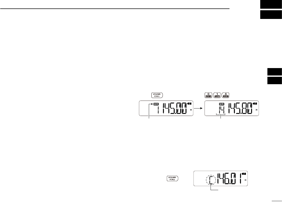
D Using the keypad
q Push [VFO/MR/CALL] several times to select the memory
mode.
• “X” appears.
w To select a desired channel, enter the 3 digits of the chan-
nel number using the keypad.
• Blank channels are also selectable.
• Entering one or two digits, and then pushing [# ENT] also se-
lects a memory channel.
• Example— selecting memory channel “14”
■ Selecting the Call channel
➥ Push [VFO/MR/CALL] several times to select the Call
channel.
• “C” appears instead of the memory channel number.
Appears
Push
Appears
Push
The memory channel
is selected.
6
MEMORY/CALL OPERATION
1
2
3
4
7
8
9
10
11
12
13
14
15
16
17
18
19
25
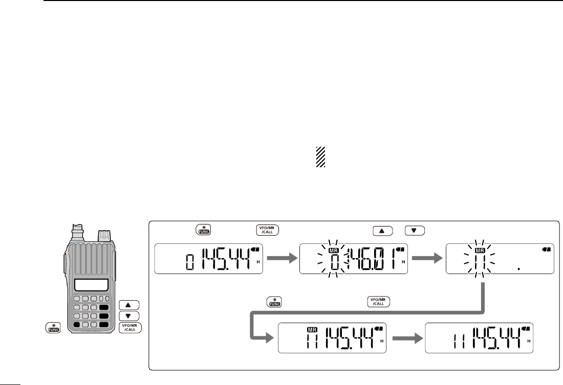
q Push [VFO/MR/CALL] several times to select the VFO
mode.
w Set a desired frequency. (p. 16)
➥ If desired, set other data (e.g. offset frequency, duplex
direction, tone squelch, etc.).
e Push [FUNC](M), and then [VFO/MR/CALL].
• “X” and the memory channel number blink.
• Select the Call channel mode to program the Call channel.
r Push [] or [] to select a desired channel.
• Select “1A/1B” to “3A/3B” to program a scan edge channel.
t Push [FUNC](M), and then push and hold [VFO/MR/
CALL] for 1 sec. to store the entry.
• 3 beeps sound.
• If you continue to push and hold [VFO/MR/CALL] for 1 sec.
after programming, the memory channel number automatically
increases.
NOTE: To cancel programming, push [VFO/MR/CALL]
before storing the entry in step t.
The VFO mode
Push or to select channel 11.
Push , and then .
Return to the VFO mode.
Push , then push and hold for 1 sec. to program.
• Example— programming 145.440 MHz into memory channel 11 (a blank channel).
■
Channel programming
6MEMORY/CALL OPERATION
26
6
6
MEMORY/CALL OPERATION
This function transfers a memory channel’s contents to
VFO (or another memory/Call channel). This is useful when
searching for signals around a memory channel frequency
and for recalling the offset frequency, subaudible tone fre-
quency etc.
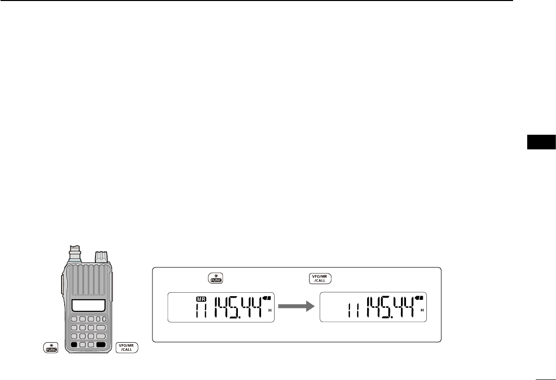
D Memory/Call➪VFO
q Select a memory (Call) channel to be copied.
➥ Push [VFO/MR/CALL] several times to select the
memory or Call channel mode, and then push [] or
[] to select a desired channel.
w Push [FUNC](M), and then push and hold [VFO/MR/
CALL] for 1 sec. to transfer the selected memory contents
to the VFO mode.
• The VFO mode is automatically selected.
D Memory/Call➪memory/Call
q Select a memory or Call channel to be copied.
➥ Push [VFO/MR/CALL] several times to select the
memory mode or the Call channel mode, and then
push [] or [] to select a desired channel.
w Push [FUNC](M), and then push [VFO/MR/CALL].
• “X” and “--” blink.
• Do not hold [VFO/MR/CALL] for more than 1 sec., otherwise
the memory contents will be copied to the VFO mode.
e Push [] or [] to select the target memory or Call chan-
nel.
r Push [FUNC](M), and then push and hold [VFO/MR/
CALL] for 1 sec. to copy.
• Example— copying memory channel 11 to the VFO mode.
Memory mode
Push , then push and hold for 1 sec.
VFO mode.
■ Copying memory/Call contents 1
2
3
4
5
7
8
9
10
12
11
14
13
15
16
17
18
19
27
6MEMORY/CALL OPERATION
■
Clearing memory contents
The contents of programmed memories can be cleared
(erased).
q For only the U.S.A. version, select any mode other than
the weather channel mode.
w Push [FUNC](M), and then push [VFO/MR/CALL].
e Push [] or [] to select a channel to be cleared.
r Perform the following operation within 1.5 sec., otherwise
the transceiver returns to the memory mode without clear-
ing memory.
- Push [FUNC](M), and then momentarily push [VFO/MR/
CALL].
- Push [FUNC](M), and then push and hold [VFO/MR/
CALL] for 1 sec.
• The channel contents are cleared.
t Push [VFO/MR/CALL] to return to the previous mode.
NOTE: Be careful!— the contents of cleared memories
CANNOT be recalled.
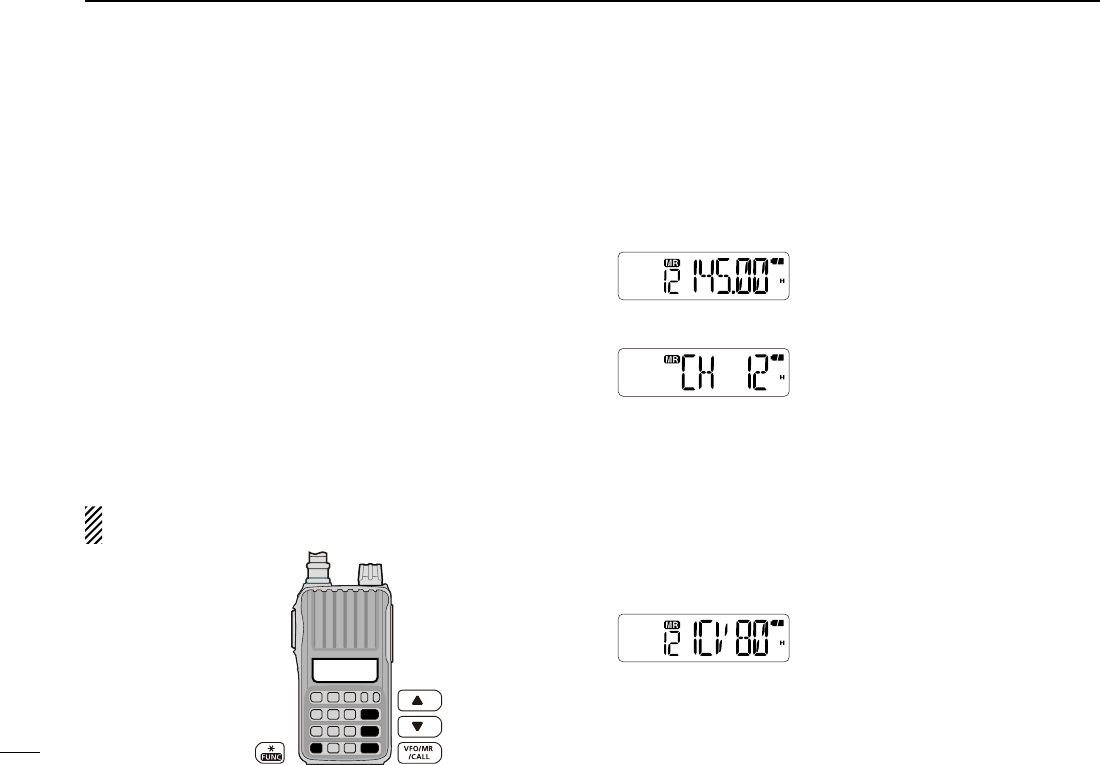
■ Display type
During memory mode operation, the transceiver has 3 dis-
play types to suit your operating style.
Set the display type in the Initial Set mode. (p. 46)
“Frequency display”
Displays the programmed frequency.
“Channel number display”
Displays the memory channel num-
ber. Only programmed channels are
displayed, and modes other than the
memory mode cannot be selected.
• When the channel number display type is selected, only the follow-
ing functions can be performed.
- Scan function (p. 30) - Out put power setting (p. 17)
- DTMF memory function (p. 35) - Key lock function (p. 18)
- The scan pause timer setting, the function key timer setting, the
LCD backlight setting, the VOX-related settings, the microphone
gain setting, and the DTMF TX key setting in the Set mode.
“Channel name display”
Displays the channel name you have
assigned. Only programmed chan-
nels are displayed.
• If no channel name is programmed, the programmed frequency
will be displayed.
• Push [MONI] to display the operating frequency.
28
6
6
MEMORY/CALL OPERATION
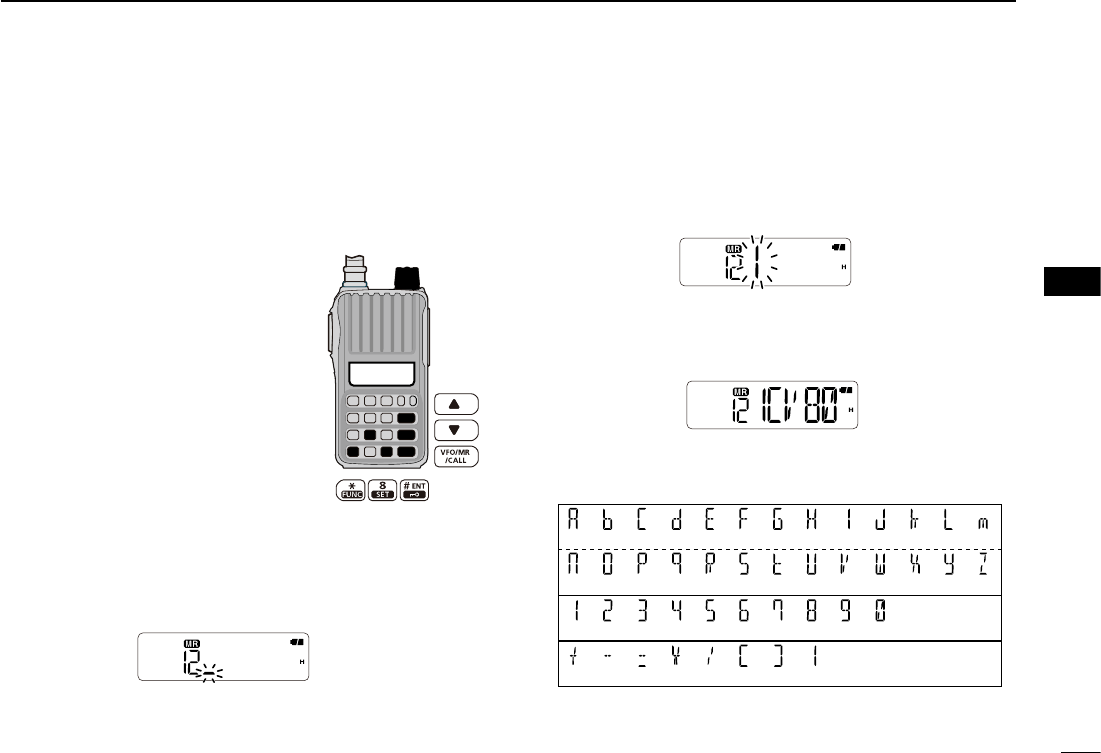
■
Programming a channel name
Each memory channel can be programmed with an alphanu-
meric name for easy recognition and can be displayed inde-
pendently by channel. Up to 5 characters can be used for a
channel name.
q While pushing and holding [] and
[], turn the power ON to enter the
Initial Set mode.
w Push []/[] to select the channel
name display item. (dSP)
e Rotate [VOL] to select the channel
name display type, “dSP.nm.”
r Push [# ENT] to exit the Initial Set
mode.
t Push [VFO/MR/CALL] several times
to select the memory mode.
• Select the Call channel to program a
Call channel name.
y Push [] or [] to select a desired channel.
u Push [FUNC](M), and then [SET](8) to enter the channel
name programming mode.
• A cursor blinks for the first character.
i Rotate [VOL] to select a desired character.
• The selected character blinks.
• Push [] to move the cursor right, push [] to move the cur-
sor left.
o Repeat step i until the desired channel name is pro-
grammed.
!0 Push [# ENT] to exit the programming mode.
D Usable characters
[VOL]
(J)
(W)
(0)
(
I
)
(V)
(9)
(A)
(n)
(1)
(
+
)
(H)
(U)
(8)
(
:
)
(C)
(P)
(3)
(
=
)
(F)
(S)
(6)
(
(
)
(G)
(t)
(7)
(
)
)
(d)
(q)
(4)
(
∗
)
(k)
(X)
(L)
(y)
(m)
(Z)
(b)
(O)
(2)
(
-
)
(E)
(R)
(5)
(
/
)
(Space)
1
3
2
4
5
7
8
9
10
11
12
13
14
15
16
17
18
19
29
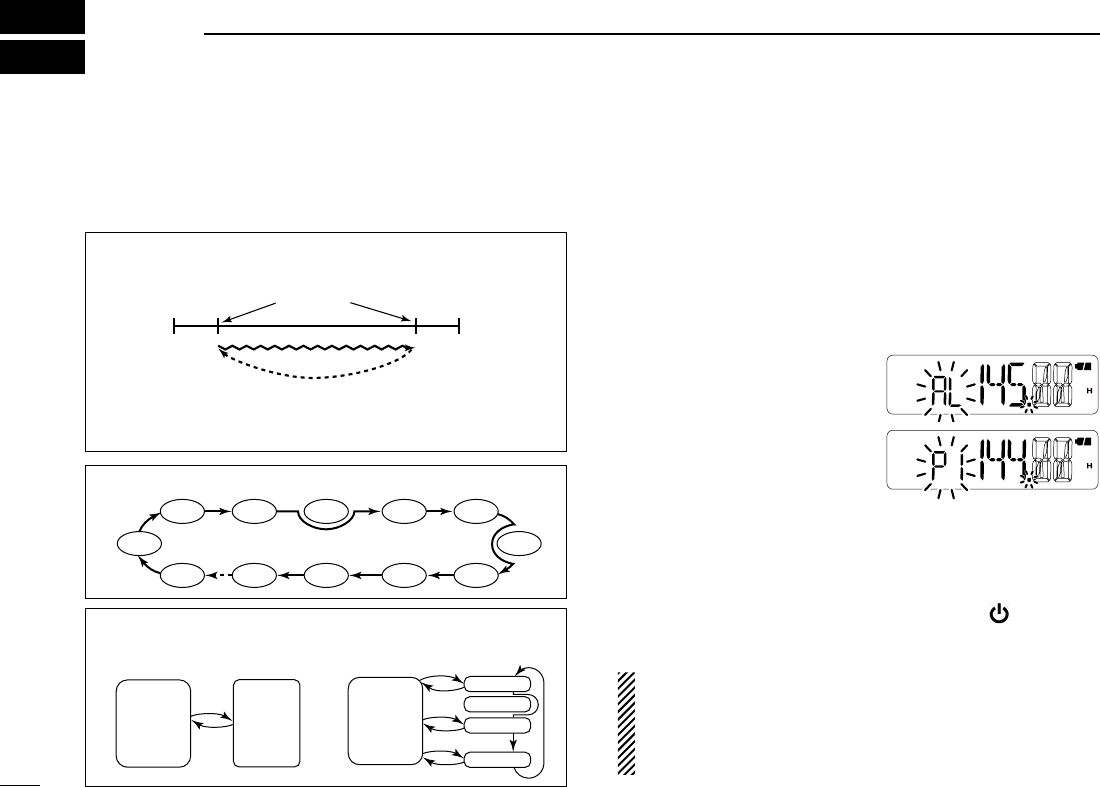
■ Scan types
A scan automatically searches for signals, and makes it
easier to locate new stations for contact or listening purposes.
■ Programmed scan
A programmed scan repeatedly scans between two user
programmed frequencies (memory channels “1A–3A” and
“1b–3b”), or scans between upper and lower band edges.
This scan is useful for checking for signals within a specific
frequency range, such as repeater output frequencies, etc.
q Push [VFO/MR/CALL] several times to select the VFO
mode.
w Push [FUNC](M), and then
[SCAN](5) to start a scan.
e Push [FUNC](M), and then
[SET](8) several times to se-
lect a desired scan type be-
tween “P1,” “P2,” “P3” or “AL.”
• “AL” for full scan, “P1,” “P2” and “P3” for programmed scan be-
tween the programmed scan edge channels “1A”–“1b,” “2A”–
“2b” and “3A”–“3b.”
• To change the scan direction, push [] or [].
r To cancel the scan, push any key except [ ], []/[],
[MONI] or [FUNC](M).
NOTE: Scan edge channels, 1A–3A/1b–3b, must be pro-
grammed in advance. Program them in the same manner
as regular memory channels. (p. 25)
If identical frequencies are programmed into the scan
edge channels, the programmed scan will not function.
PROGRAMMED SCAN (See the next topic)
The Programmed scan P1 scans between 1A and 1b, P2
scans between 2A and 2b, and P3 scans between 3A and 3b
frequencies.
Band
edge Band
edge
1A
2A
3A
1b
2b
3b
Scan edges
Scan
Jump
MEMORY (SKIP) SCAN (p. 30)
SKIP SKIP
Mch 1
Mch 0
Mch 2 Mch 3 Mch 4 Mch 5
Mch 10
Mch 199
Mch 9 Mch 8 Mch 7
Mch 6
PRIORITY WATCH (p. 31)
• Memory/Call channel watch • Memory scan watch
5 sec.
VFO
frequency
Memory
(Call)
channel
5 sec.
VFO
frequency
SKIP
Mch 0
Mch 1
Mch 2
Mch 199
SCAN OPERATION
7
30
7
■ Memory Scan
A memory scan repeatedly scans memory channels, except
those set as skip channels.
q Push [VFO/MR/CALL] several times to select the mem-
ory mode.
• “X” appears.
w P u s h [FUNC](M), t h e n
[SCAN](5) to start the scan.
• To change the scan direction,
push [] or [].
e To cancel the scan, push any key except [ ], []/[],
[MONI] or [FUNC](M).
■ Setting skip channels
In order to speed up the scan rate, you can set the memory
channels you don’t want to scan as skip channels.
q Select a memory channel to be skipped.
➥ Push [VFO/MR/CALL] several times to select the
memory mode, and then push [] or [] to select a
desired channel.
w Push [FUNC](M), and then
[SKIP](6) to turn the skip
setting ON or OFF.
•
“SKIP” appears when the chan-
nel is set as a skip channel.
■ Scan resume setting
When a signal is received during a scan, the scan resume
setting determines what action the transceiver takes. The
transceiver has 2 scan resume settings, as described below.
Use the Set mode to select the one which best suits your
needs.
q
Push [FUNC](M), and then [SET](8) to enter the Set mode.
w Push [] or [] to select the scan pause timer item (SCt,
or SCP).
e Rotate [VOL] to select a desired scan pause option.
• Pause scan
The scan pauses until the received signal disappears,
and then resumes after 2 sec.
• Timer scan
The scan pauses for 5 sec., 10 sec. or 15 sec., and then
resumes.
r Push [# ENT] to exit the Set mode.
Appears
[VOL] Pause scan
Timer scan (15 sec.)
7
SCAN OPERATION
1
2
3
4
5
6
8
9
10
11
12
13
14
15
16
17
18
19