ICOM orporated 325400 VHF Transceiver User Manual 2
ICOM Incorporated VHF Transceiver 2
Contents
- 1. User Manual 1
- 2. User Manual 2
User Manual 2
31
■ Priority watch
A priority watch checks for signals on “priority channels”
while operating on a VFO frequency.
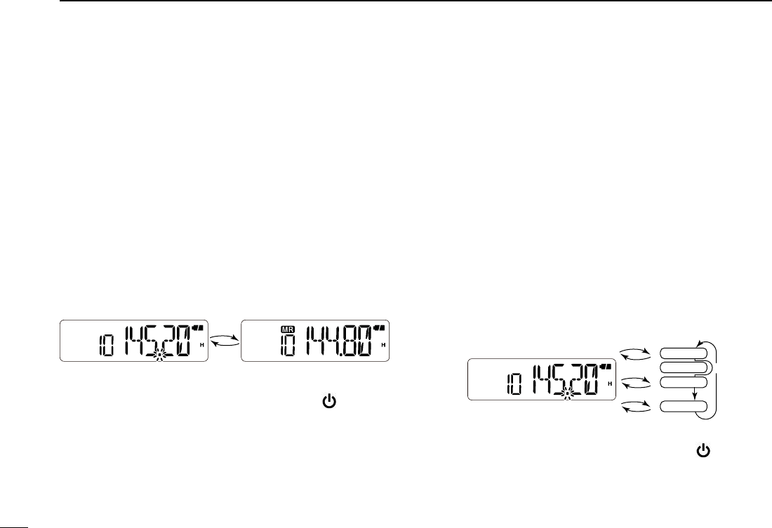
D Memory or Call channel watch
While operating on a VFO frequency, the memory or Call
channel watch checks for signals on the selected channel
every 5 sec.
q Select a desired memory channel or the Call channel.
w Push [FUNC](M), and then [PRIO](7) to start the watch.
• The decimal point “.”, on the frequency readout blinks.
• When a signal is detected on the channel, the watch resumes
according to the scan resume setting. (p. 30)
e To cancel the watch, push any key except [ ], []/[],
[MONI], [FUNC](M), or [PTT].
D Memory scan watch
While operating on a VFO frequency, a memory scan watch
checks for signals on each memory channel in sequence,
every 5 sec.
q Push [VFO/MR/CALL] several times to select the memory
mode.
w Push [FUNC](M), and then [SCAN](5) to start a memory
scan.
e Push [FUNC](M), and then [PRIO](7) to start the watch.
• The VFO mode is selected, and the decimal point “.”, on the fre-
quency readout blinks.
• When a signal is detected on a channel, the watch resumes ac-
cording to the scan resume setting. (p. 30)
r To cancel the watch, push any key except [ ], []/[],
[MONI], [FUNC](M), or [PTT].
Memory channelVFO frequency
5 sec.
VFO frequency
5 sec.
Memory scan
Mch 0
Mch 1
Mch 2
Mch 199
SKIP
7SCAN OPERATION
32
7
8
8
TONE SQUELCH AND POCKET BEEP
D
Tone squelch and DTCS squelch
The tone squelch (CTCSS) or DTCS squelch opens only
when receiving a signal that includes a matched CTCSS tone
or DTCS code, respectively. You can silently wait for calls
using the same tone or code. Separate tone frequencies can
be set for repeater and tone squelch/pocket beep operation.
D
Pocket beep
The pocket beep function uses subaudible tones or DTCS
codes for calling, and can be used as a “common pager” to
inform you that someone has called while you were away
from the transceiver.
• Recommended CTCSS tones (unit: Hz)
67.0
69.3
71.9
74.4
77.0
79.7
82.5
85.4
88.5
91.5
94.8
97.4
100.0
103.5
107.2
110.9
114.8
118.8
123.0
127.3
131.8
136.5
141.3
146.2
151.4
156.7
162.2
167.9
173.8
179.9
186.2
192.8
203.5
210.7
218.1
225.7
233.6
241.8
250.3
• Recommended DTCS code
D
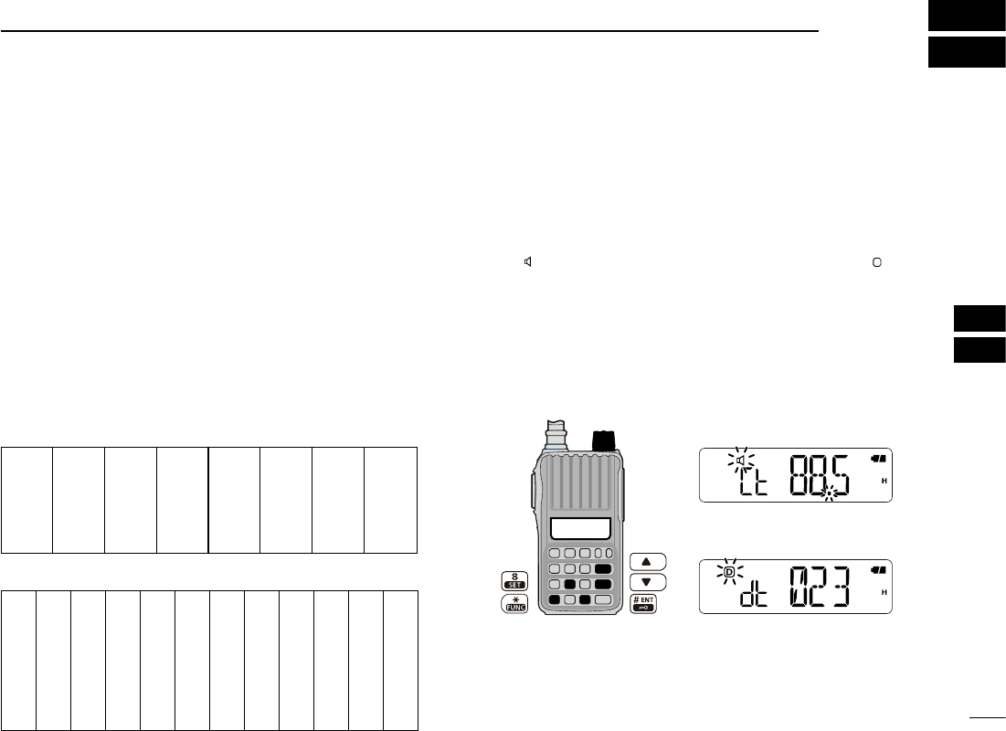
Setting CTCSS tone or DTCS code
q Push [FUNC](M), and then [SET](8) to enter the Set mode.
w Push [] or [] to select the CTCSS tone item (Ct) or
the DTCS code item (dt).
• “ ” blinks when selecting the CTCSS tone item, and “
D
” blinks
when selecting the DTCS code item.
e Rotate [VOL] to select a desired CTCSS tone or DTCS
code.
• The recommended CTCSS tone or DTCS code are shown to
the left.
r Push [# ENT] to exit the Set mode.
■
Tone/DTCS squelch and pocket beep
023
025
026
031
032
043
047
051
054
065
071
072
073
074
114
115
116
125
131
132
134
143
152
155
156
162
165
172
174
205
223
226
243
244
245
251
261
263
265
271
306
311
315
331
343
346
351
364
365
371
411
412
413
423
431
432
445
464
465
466
503
506
516
532
546
565
606
612
624
627
631
632
654
662
664
703
712
723
731
732
734
743
754
DTCS code setting
CTCSS tone setting
[VOL]
1
2
3
4
5
6
9
10
11
12
13
14
15
16
17
18
19
33
D
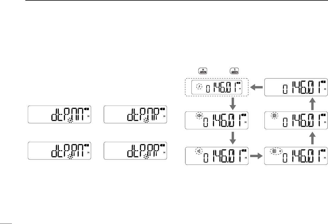
Setting DTCS polarity
For DTCS operation, the polarity setting is also configurable,
as well as the code setting. If the polarity is different, the
DTCS squelch never opens, even when receiving a signal
that includes a matched DTCS code.
q Push [FUNC](M), and then [SET](8) to enter the Set mode.
w Push [] or [] to select the DTCS polarity item (dtP).
e Rotate [VOL] to select a desired polarity setting between
“dtP.nn” (normal), “dtP.nR” (TX: normal, RX: reverse), “dtP.Rn”
(TX: reverse, RX: normal) and “dtP.RR” (reverse).
r Push [# ENT] to exit the Set mode.
D
Operation
q Set a desired operating frequency, and then a CTCSS tone
or a DTCS code.
w Push
[FUNC](M), and then [TONE](1)
.
•
Repeat step w several times to activate a desired tone function.
e Operate the transceiver in a normal way.
8TONE SQUELCH AND POCKET BEEP
TX/RX: Normal polarity TX: Normal, RX: Reverse
TX: Reverse, RX: Normal TX/RX: Reverse polarity
Function OFF
Push , and then to select the tone function in sequence.
Tone squelch with
pocket beep
Tone squelch
DTCS squelch
DTCS squelch with
pocket beep
Repeater tone

34
8
r When receiving a signal that includes a matched tone
or code, the squelch opens and the signal can be heard.
When the pocket beep function is activated.
• Beep tones sound and “ ” blinks. To stop the beeps and blink-
ing, push any key.
• When the received signal’s tone/code does not match, the
squelch does not open. However, the signal indicator shows the
signal strength.
• To open the squelch manually, push and hold [MONI].
t Push [PTT] to answer.
■ Tone scan
By monitoring a signal from a repeater, pocket beep or
squelch function operation, you can determine the subaudi-
ble tone required to access the repeater or open the squelch.
q Set a frequency to be checked for a tone frequency or
DTCS code.
w Push
[FUNC](M), and then [TONE](1)
.
•
Repeat step w several times to activate a desired tone function.
• The tone scan can be made even if the tone function is not se-
lected.
e Push [FUNC](M), and then [T.SCAN](3) to start a tone
scan.
• To change the scan direction, push [] or [].
r When a tone frequency or DTCS code is matched, the
squelch opens and the tone frequency or code is tempo-
rarily programmed into the selected mode.
• When a tone frequency or DTCS code is detected, the tone
scan pauses according to the scan resume setting (p. 30)
• The decoded CTCSS tone frequency or DTCS code is used ac-
cording to the selected tone function type in step
w
.
- No indication : Cannot be used for operation.
-“ ” : CTCSS tone encoder (repeater tone)
-“ ” : CTCSS tone encoder/decoder
-“
D
” : DTCS tone encoder/decoder
t To cancel the scan, push any key except [ ], []/[],
[MONI] or [FUNC](M).
8
TONE SQUELCH AND POCKET BEEP
1
2
3
4
5
6
7
9
10
11
12
13
14
15
16
17
18
19
35
The DTMF codes are used for autopatching, accessing re-
peaters, controlling other equipment, and other operations.
The transceiver has 16 DTMF memory channels (d0–d9,
dA, db, dC, dd, dE, dF) for storage of often-used DTMF code
sequence of up to 24 digits.
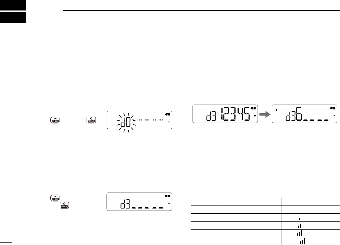
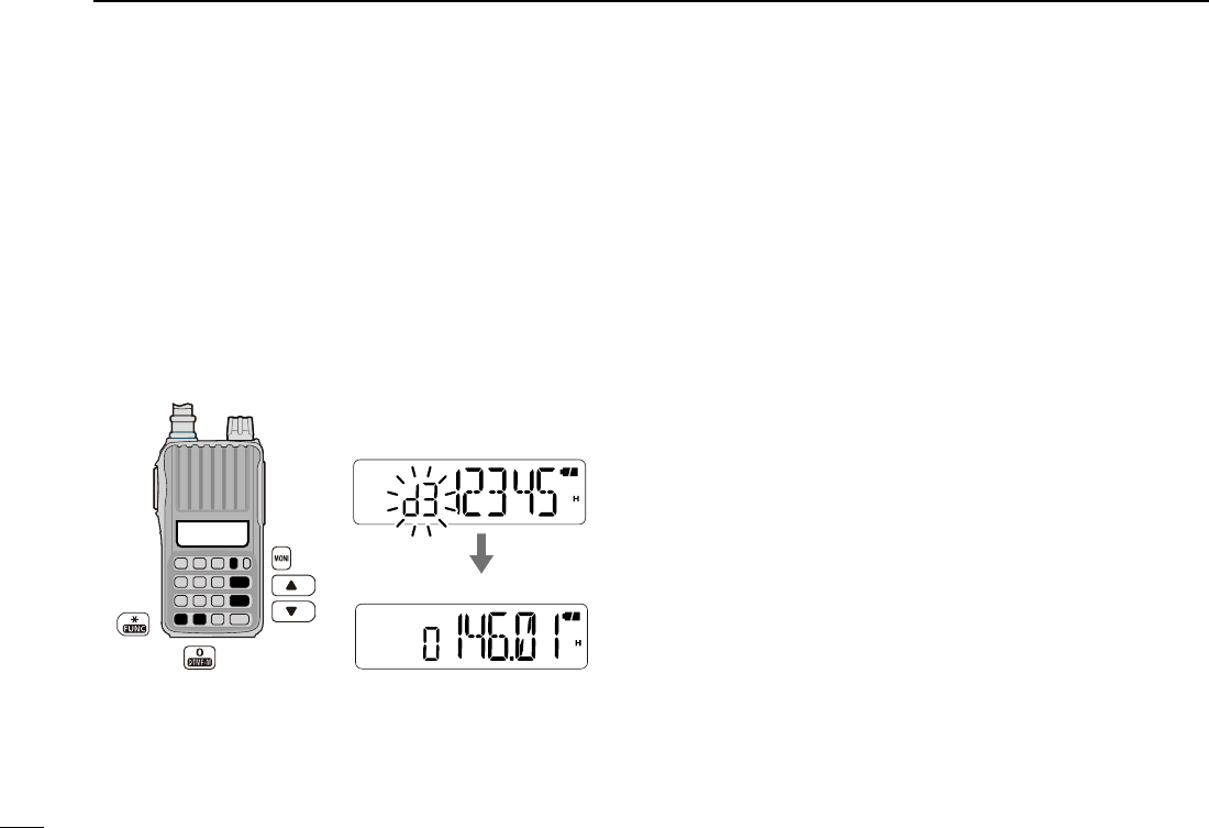
q Push
[FUNC](M), and then [
DTMF.M](0) to enter the
DTMF memory mode.
w Push [] or [] to select a desired DTMF memory chan-
nel.
• If programmed, the previously programmed DTMF code is dis-
played.
e Push
[FUNC](M), and then push and hold [
DTMF.M](0) for
1 sec. to enter the programming mode.
• “_ _ _ _ _” appears.
• Programmed memories will be cleared by this operation.
r Push keys to input a desired DTMF code sequence of up
to 24 digits.
• [0]–[9] inputs “0”–“9,” [MONI] inputs “A,” [] inputs “B,” []
inputs “C,” [VFO/MR/CALL] inputs “D,” [
M
] inputs “
M
(E)” and [#
ENT] inputs “# (F).”
• If a digit is mistakenly input, push [PTT] momentarily, then re-
peat from step e.
t Repeat step r until the desired code is input.
y Push [PTT] to store the DTMF code sequence and exit
the programming mode.
• After the 24th digit is input, the transceiver automatically stores
the code sequence and returns to step w.
u Push [VFO/MR/CALL] to exit the DTMF memory.
•
Programming mode indication
The programming mode consists of 5 pages.
Push , and then .
Push , and then push
and hold for 1 sec.
The next page appears when
the 6th digit has been input.
■
Programming a DTMF code sequence
DTMF MEMORY
9
Page Digits Indication
1st 1st to 5th No indication.
2nd 6th to 10th “ ” appears.
3rd 11th to 15th “ ” appears.
4th 16th to 20th “ ” appears.
5th 21st to 24th “ ” blinks.

36
9
9
DTMF MEMORY
The transceiver has 3 methods of transmitting a DTMF code
sequence. Select a desired option in the Set mode.
q Push [FUNC](M), and then [SET](8) to enter the Set mode.
w Push [] or [] to select the DTMF TX key item (dmt).
e Rotate [VOL] to select a desired option.
• dmt.k : Transmits the appropriate DTMF code assigned to the
pushed key.
• dmt.m :
Transmits the programmed DTMF code sequence in the
DTMF memory channel assigned to the pushed key.
• dmt.t : No DTMF code can be transmitted. However, while
pushing and holding [PTT], pushing either the [] or
[] transmits a 1750 Hz tone burst signal.
r Push [# ENT] to exit the Set mode.
D Manual DTMF code transmission
First, set the DTMF TX key to
“dmt.k” in the Set mode.
➥ While pushing and holding [PTT], push the desired keys
to transmit a DTMF code sequence manually.
• Push [0]–[9] for “0”–“9,” [MONI] for “A,” [] for “B,” [] for “C,”
[VFO/MR/CALL] for “D,” [M] for “M,” and [# ENT] for “#.”
D Using a DTMF memory channel
First, set the DTMF TX key to
“dmt.m” in the Set mode.
➥ While pushing and holding [PTT], push one of the keys
to transmit the programmed DTMF code sequence in the
DTMF memory.
• Pushing [0] to [9], [MONI](A), [](B), [](C), [VFO/MR/CALL]
(D),
[
M
]
(E), or
[
# ENT
]
(F) transmits a DTMF code channel (d0–
d9, dA, dB, dC, dD, dE or dF) respectively.
D 1750 Hz tone
To access some European repeaters, the transceiver must
transmit a 1750 Hz tone burst signal.
• This tone can be used as a ‘Call signal’ in countries out of Europe.
First, set the DTMF TX key to
“dmt.t” in the Set mode.
➥ While pushing and holding [PTT], push and hold either
the [] or [] for 1 or 2 sec. to transmit a 1750 Hz tone
burst signal.
• While pushing and holding the key, the tone is transmitted.
■
Transmitting a DTMF code sequence 1
2
3
4
5
6
7
8
10
11
12
13
14
15
16
17
18
19
37
9DTMF MEMORY
■ Confirming a DTMF memory
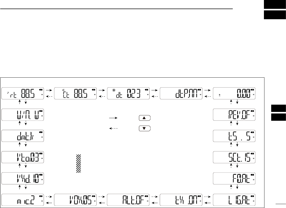
A DTMF memory can be confirmed with a DTMF tone.
q Push
[FUNC](M), and then [
DTMF.M](0) to enter the
DTMF memory mode.
w Push [] or [] to select a desired DTMF memory chan-
nel.
e Push [MONI] to confirm the DTMF memory contents.
• The programmed DTMF code sequence sounds.
• After sounding, the transceiver exits the DTMF memory mode.
■ Setting DTMF transfer speed
When slow DTMF transmission speeds are required with
DTMF memory transmission (as for some repeaters), the
transceiver’s rate of DTMF transmission can be adjusted in
the Initial Set mode.
q While pushing and holding [] and [], turn the power
ON to enter the Initial Set mode.
w Push [] or [] to select the DTMF speed item. (dtd)
e Rotate [VOL] to select a desired speed.
• dtd. 1 : 100 msec. interval; 5.0 cps rate
• dtd. 2 : 200 msec. interval; 2.5 cps rate
• dtd. 3 : 300 msec. interval; 1.6 cps rate
• dtd. 5 : 500 msec. interval; 1.0 cps rate
(cps=characters per second)
r Push [# ENT] to exit the Initial Set mode.
E
xits the DTMF memory mode.
The programmed DTMF code
sequence sounds.
38
9
10
10
SET MODES
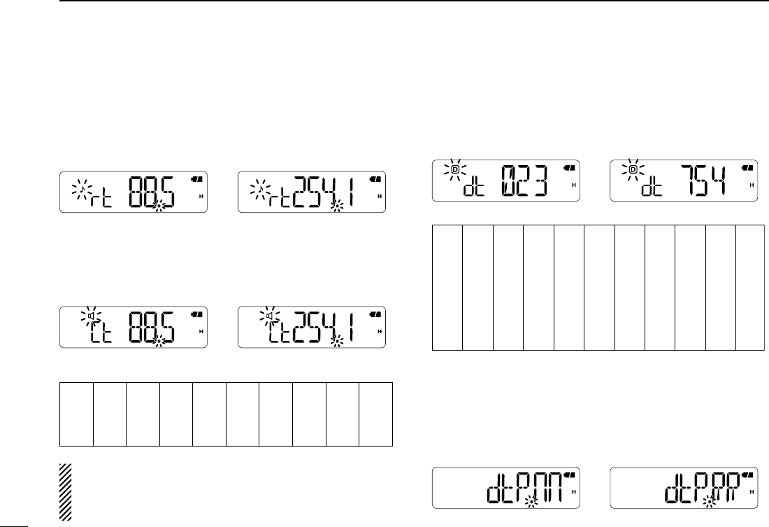
■ Set mode programming
The Set mode is used to change the settings of the trans-
ceiver’s functions.
D Set mode operation
q
Push [FUNC](M), and then [SET](8) to enter the Set mode.
w Push [] or [] to select the desired item.
e Rotate [VOL] to select the option or value.
r To exit the Set mode, push [# ENT].
• Repeater tone
frequency (p. 39)
• Tone squelch
frequency (p. 39) • DTCS code (p. 39) • DTCS polarity (p. 39) •
Frequency offset (p. 40)
•
Reverse
duplex
functon
(p. 40)
• Tuning step (p. 40)
•
Scan resume setting (p. 40)
•
Function key timer (p. 40)
• LCD backlight (p. 41)• TX permission (p. 41)• VOX gain (p. 41)
• Microphone gain (p. 41)
• Weather alert* (p. 41)
• VOX delay (p. 41)
• VOX time-out timer (p. 42)
• DTMF TX key (p. 42)
• Operating mode (p. 42)
*Appears for only the U.S.A.
version transceivers.
: Push
: Push
NOTE: When the display type setting (pp. 27, 46) is set
to “CH” in the Initial Set mode, and accessing the Set
mode from the memory mode, most of Set mode items
do not appear.
1
2
4
3
5
6
7
8
11
12
14
13
15
16
17
18
19
39
■ Set mode items
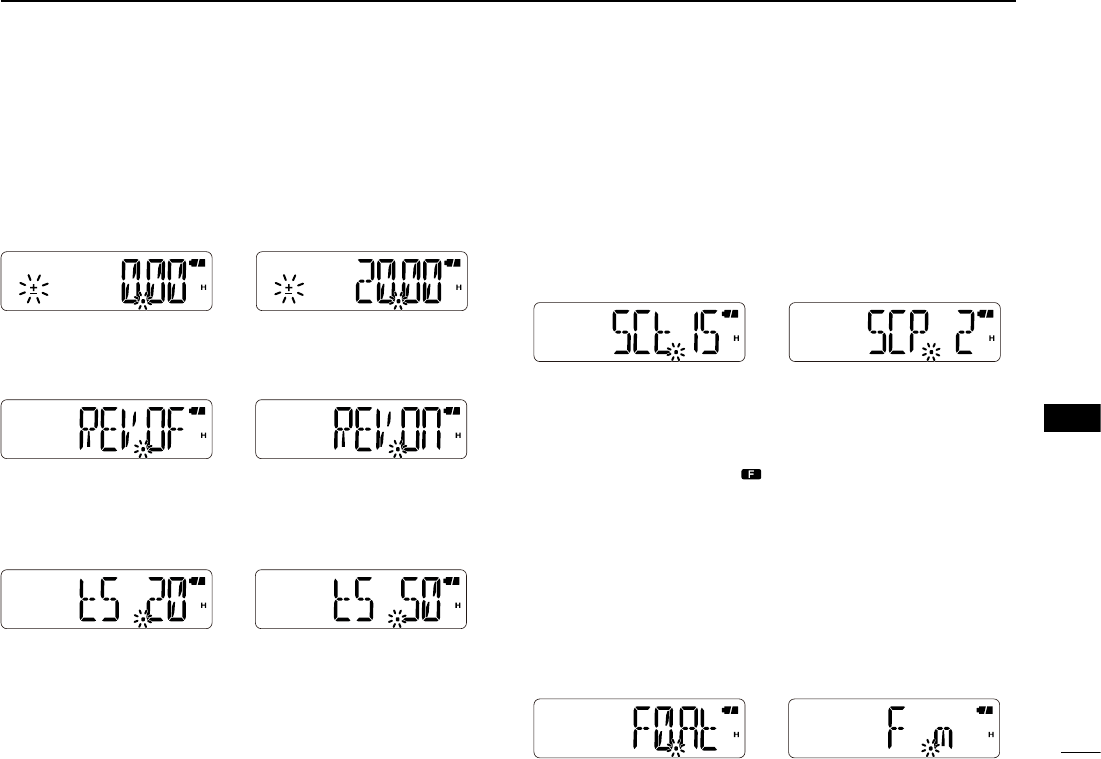
D Repeater tone frequency
Selects one of 50 subaudible tone frequencies used to ac-
cess the repeaters.
• 67.0–254.1 Hz (default: 88.5 Hz)
D Tone squelch frequency
Selects one of tone frequencies for tone squelch or pocket
beep operation.
• 67.0–254.1 Hz (default: 88.5 Hz)
• Usable subaudible tone frequencies (unit: Hz)
67.0
69.3
71.9
74.4
77.0
79.7
82.5
85.4
88.5
91.5
94.8
97.4
100.0
103.5
107.2
110.9
114.8
118.8
123.0
127.3
131.8
136.5
141.3
146.2
151.4
156.7
159.8
162.2
165.5
167.9
171.3
173.8
177.3
179.9
183.5
186.2
189.9
192.8
196.6
199.5
203.5
206.5
210.7
218.1
225.7
229.1
233.6
241.8
250.3
254.1
The transceiver has 50 tone frequencies and conse-
quently their spacing is narrow compared with units hav-
ing 38 tones. Therefore, some tone frequencies may re-
ceive interference from adjacent tone frequencies.
D DTCS Code
Selects one of 104 DTCS (both encoder/decoder) codes.
• 023–754 (default: 023)
• Available DTCS codes
023
025
026
031
032
036
043
047
051
053
125
131
132
134
143
145
152
155
156
162
245
246
251
252
255
261
263
265
266
271
356
364
365
371
411
412
413
423
431
432
506
516
523
526
532
546
565
606
612
624
054
065
071
072
073
074
114
115
116
122
165
172
174
205
212
223
225
226
243
244
274
306
311
315
325
331
332
343
346
351
445
446
452
454
455
462
464
465
466
503
627
631
632
654
662
664
703
712
723
731
732
734
743
754
D DTCS Polarity
Selects the DTCS polarity between “dtP.nn” (normal), “dtP.nR”
(TX: normal, RX: reverse), “dtP.Rn” (TX: reverse, RX: normal) and
“dtP.RR” (reverse). (default: dtP.nn)
The DTCS code’s polarity for transmitting or receiving can
be independently set by this item.
TX/RX: Normal polarity TX/RX: Reverse polarity
10 SET MODES
40
10
10
SET MODES
D Frequency offset
Selects the frequency offset between 0 and 20 MHz, for re-
peater operation.
The frequency offset means the difference between the
transmit and receive frequencies.
(default: differs depending on the version)
D Reverse duplex function
Turns the reverse duplex function ON or OFF. (default: OFF)
D Tuning step
Selects the tuning step from 5, 10, 12.5, 15, 20, 25, 30 and
50 kHz. (default: differs depending on the version)
D Scan resume setting
Selects the scan resume setting between SCt. 5, SCt. 10,
SCt. 15, and SCP. 2.
When a signal is received during a scan, the scan pauses
and then resumes, according to the scan resume setting.
• SCt. 5/10/15 : The scan pauses for 5, 10 or 15 sec., and then re-
sumes. (default: SCt. 15)
• SCP.2 : The scan pauses until the received signal disap-
pears, and then resumes after 2 sec.
D Function key timer
Push
[FUNC](M)
to enter the Function mode, and then push
a keypad key to activate it’s second function.
• During the Function mode, “ ” is displayed on the LCD.
Set the time between when Function mode is entered, and
how long it remains activated after you push the keypad key
to activate it’s second function.
• F0.At : Exits the Function mode immediately after a key is
pushed to activate it’s second function. (default)
• F1/2/3.At :
The Function mode remains activated for the selected pe-
riod
after a key is pushed to activate it’s second function
.
• F .m : The Function mode remains activated until
[FUNC](M)
is pushed again, even after a key is pushed
to activate
it’s second function.
1
2
3
4
5
6
7
8
9
11
12
13
14
15
16
17
18
19
41
10 SET MODES
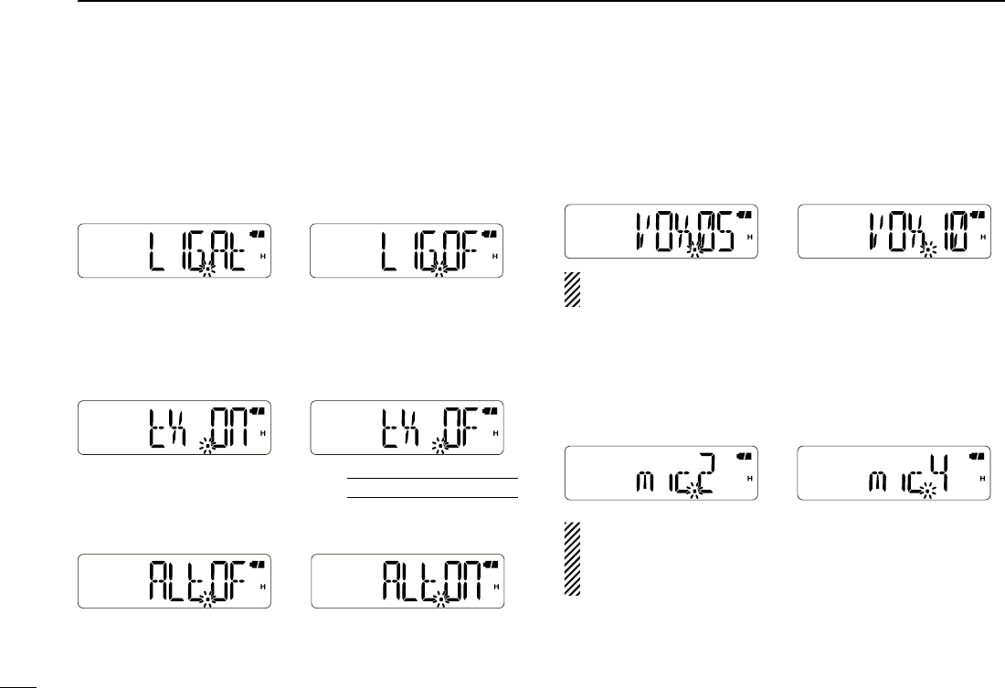
D LCD backlight
Selects the LCD backlight function.
• LIG.OF : Turns the backlight function OFF.
• LIG.ON :
Lights continuously while the transceiver is ON.
• LIG.At : Turns ON when an operation occurs, and turns OFF
after 5 sec. (default)
D TX permission
Selects whether or not to allow transmitting.
• tX .OF :
Inhibits transmitting. (Receive only)
• tX .ON : Allows transmitting. (default)
D Weather alert
Turns the Weather Alert function ON or OFF. (p. 19)
(default: OFF)
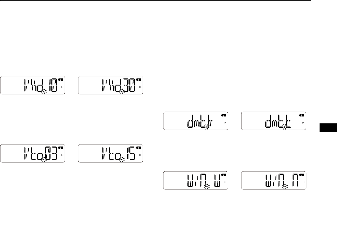
D VOX gain
Sets the VOX gain to between 1 and 10. Higher values make
the VOX function more sensitive to your voice.
To turn the VOX function OFF, select “VOX.OF.”
(default: VOX.05)
NOTE: Set the microphone gain before setting the VOX
gain. See page 52 for details of the VOX function.
D Microphone gain
Sets the microphone gain to between 1 and 4 to suit your
preference. Higher values make the microphone more sensi-
tive to your voice. (default: mic.2)
NOTE: When using the VOX function, we recommend
setting the microphone gain to 3. However, you can adjust
it to suit your operating environment (including your head-
set performance).
U.S.A. version only
42
10
10
SET MODES
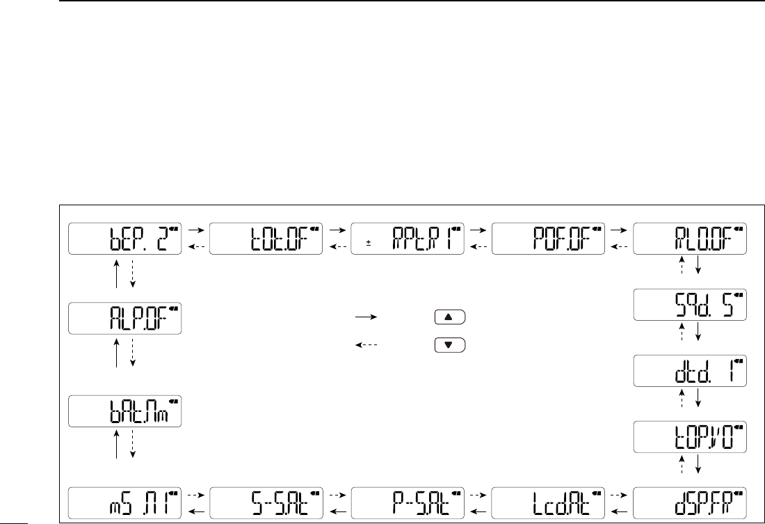
D VOX delay
Sets the VOX Delay to between “VXd.05” (0.5 sec.), “VXd.10”
(1 sec.), “VXd.15” (1.5 sec.), “VXd.20” (2 sec.), “VXd.25” (2.5
sec.) and “VXd.30” (3 sec.).
The VOX Delay is the amount of time the transmitter stays
ON after you stop speaking. (default: VXd.10)
D VOX time-out timer
Sets the VOX time-out timer to between 1, 2, 3, 4, 5, 10 and
15 min. to prevent accidental prolonged transmission for the
VOX function.
To turn the function OFF, select “Vto.OF.” (default: Vto.03)
D DTMF TX key
Selects the method to transmit a DTMF code sequence.
While pushing and holding [PTT], push one of the keys,
[0] to [9], [MONI](A), [](B), [](C), [VFO/MR/CALL](D),
[
M
]
(E),and
[
# ENT
]
(F).
• dmt.k : Transmits the appropriate DTMF code assigned to the
key. (default)
• dmt.m :
Transmits the programmed DTMF code sequence in
the DTMF memory channel assigned to the key.
• dmt.t : No DTMF code can be transmitted. However, while
pushing and holding [PTT], push either the [] or []
to transmit a 1750 Hz tone burst signal.
D Operating mode
Set the operating mode to FM or FM-N. The operating mode
is determined by the modulation of the radio signals.
(default: W/n. W)
FM mode FM-N mode
1
2
3
4
5
6
7
8
9
11
12
13
14
15
16
17
18
19
43
10 SET MODES
■
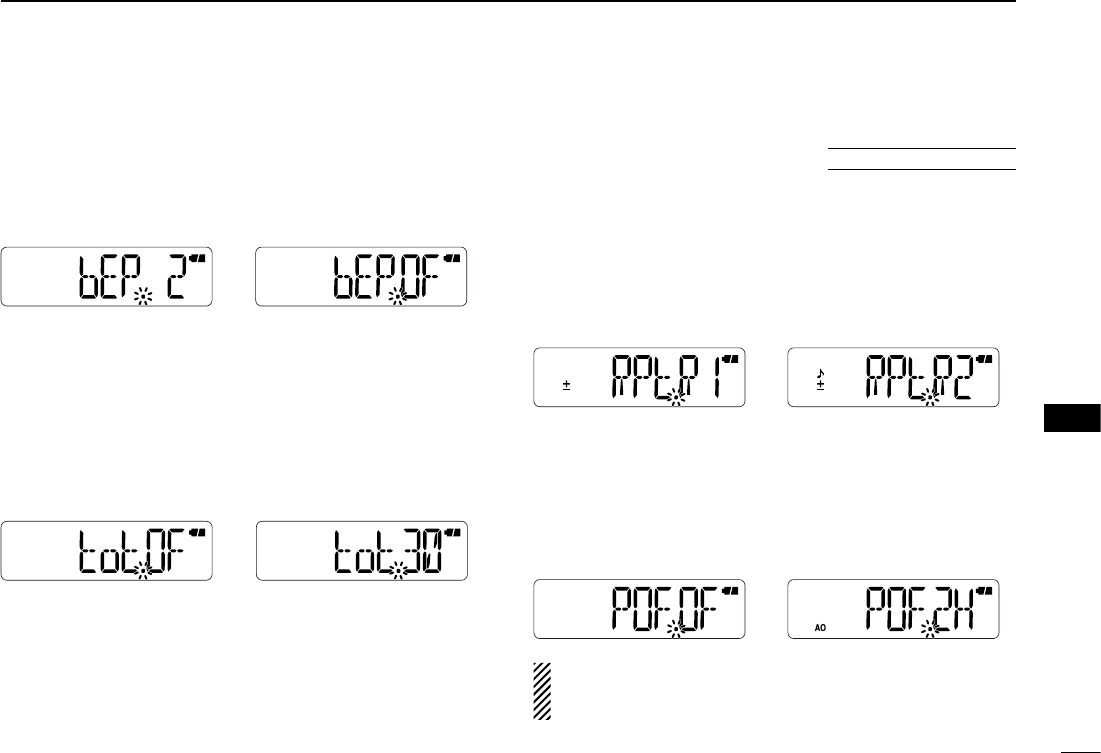
Initial Set mode programming
The Initial Set mode can be accessed at power ON and al-
lows you to set seldom-changed settings, to suit your prefer-
ence and operating style.
D Initial Set mode operation
q While pushing and holding
[] and []
, turn the power
ON to enter the Initial Set mode.
w Push [] or [] to select the desired item.
e Rotate [VOL] to select the option or value.
r To exit the Initial Set mode, push [# ENT].
• Time-out timer (p. 44) • Auto repeater* (p. 44) • Auto power-OFF (p. 44) • Lockout
(p. 45)
• Squelch delay (p. 45)
• DTMF speed (p. 45)
•
Dial assignment (p. 45)
• Display type (p. 46)• Power save (p. 46)• Select speed (p. 46) • LCD contrast (p. 46)
• Battery protection
function (p. 47)
• Microphone simple
mode (p. 47)
• Key-touch beep (p. 44)
• Auto low power (p. 47)
*Appears for only the U.S.A.
version transceivers.
: Push
: Push
44
10
10
SET MODES
■ Initial Set mode items
D Key-touch beep
Turns the key-touch beep ON (the beep level 1 to 3) or OFF.
• When changing the beep level, beeps sound at the level.
(default: bEP. 2)
D Time-out timer
To prevent accidental prolonged transmission, the trans-
ceiver has a time-out timer. This function cuts transmission
OFF after 1–30 min. of continuous transmission.
To turn the function OFF, select “tot.OF.”
• tot.OF : Turns the function OFF. (default)
• tot. 1–30 :
If continuous transmission exceeds the selected period,
the transmission will be cut off.
D Auto repeater
The Auto Repeater function automatically turns ON or OFF
the duplex operation and the tone encoder. The offset and
the repeater tone are not changed by the function. Reset
these settings, if necessary.
• RPt.OF : Turns the function OFF.
• RPt.R1 : Activates for only duplex. (default)
• RPt.R2 :
Activates for both duplex and tone.
D Auto power-OFF
The transceiver can be set to beep and automatically turn
OFF, when no key operation occurs during a specified period.
• POF.OF : Turns the function OFF. (default)
• POF.30/1H/2H :
The transceiver is automatically turned OFF when
no operation occurs during the selected period.
NOTE: The setting is maintained even after the trans-
ceiver is turned OFF by the auto power-OFF function. To
cancel the function, select “POF.OF.”
U.S.A. version only
1
2
3
4
5
6
7
8
9
11
12
13
14
15
16
17
18
19
45
10 SET MODES
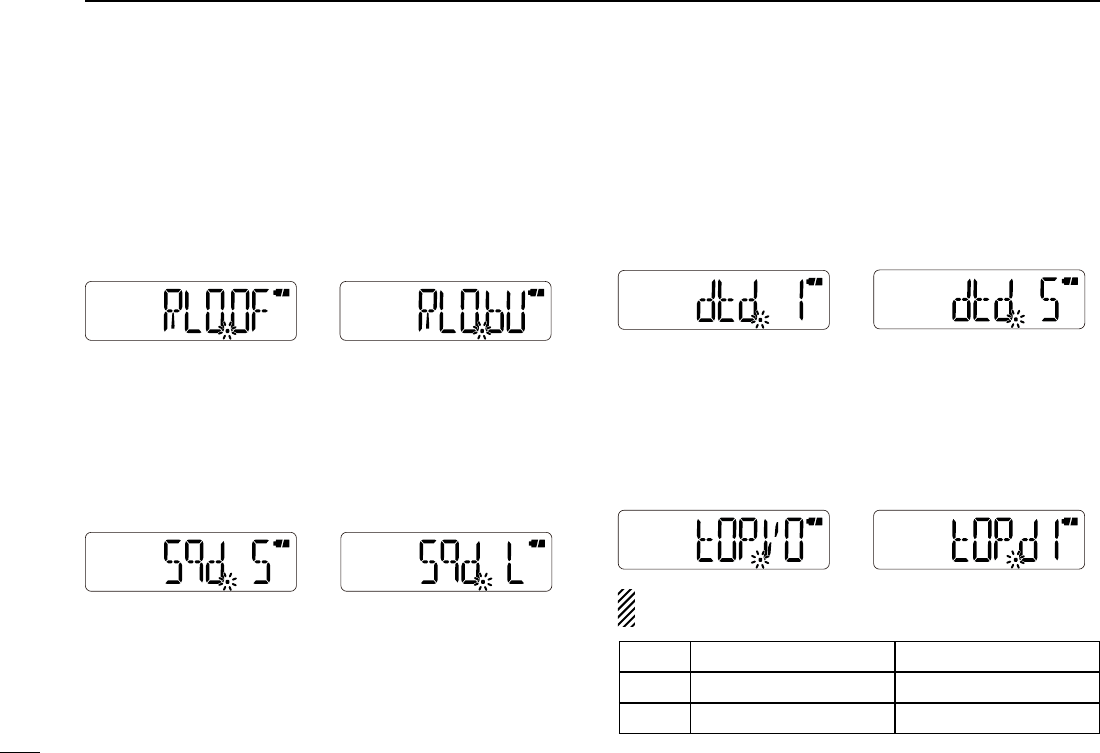
D Lockout
Selects the lockout type between repeater, busy and OFF.
• RLO.OF : Turns the function OFF (default).
• RLO.RP : The repeater lockout function inhibits transmitting when
the channel is busy, except while receiving a signal that
includes a matched tone.
• RLO.bU : The busy lockout function
inhibits transmitting while re-
ceiving a signal.
D Squelch delay
Sets the squelch delay between short and long. The delay
prevents the squelch from repeatedly opening and closing
while receiving the same signal.
• Sqd. S : Sets the squelch delay to short (default).
• Sqd. L : Sets the squelch delay to long
.
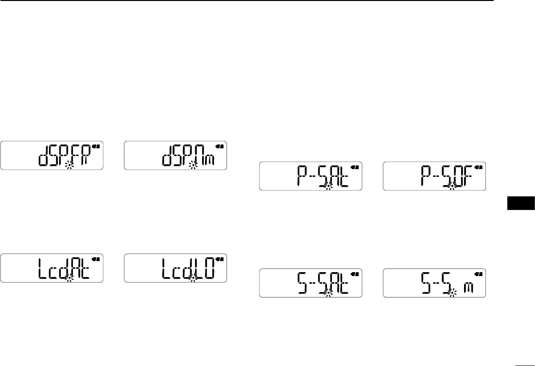
D DTMF speed
Selects a desired DTMF transfer speed.
• dtd. 1 : 100 msec. interval; 5.0 cps rate (default)
• dtd. 2 : 200 msec. interval; 2.5 cps rate
• dtd. 3 : 300 msec. interval; 1.6 cps rate
• dtd. 5 : 500 msec. interval; 1.0 cps rate
(cps=characters per second)
D Dial assignment
Selects whether or not to use [VOL] as a tuning control
in-
stead of [] and []. When [VOL] functions as a tuning con-
trol, [] and [] function as volume controls.
• tOP.VO : Audio volume control (default)
• tOP.dI : Tuning dial
[VOL] and
[]/[] function as described below, depend-
ing on the option.
Option [VOL] []/[]
tOP.VO Volume control Tuning controls
tOP.di Tuning control Volume controls
46
10
10
SET MODES
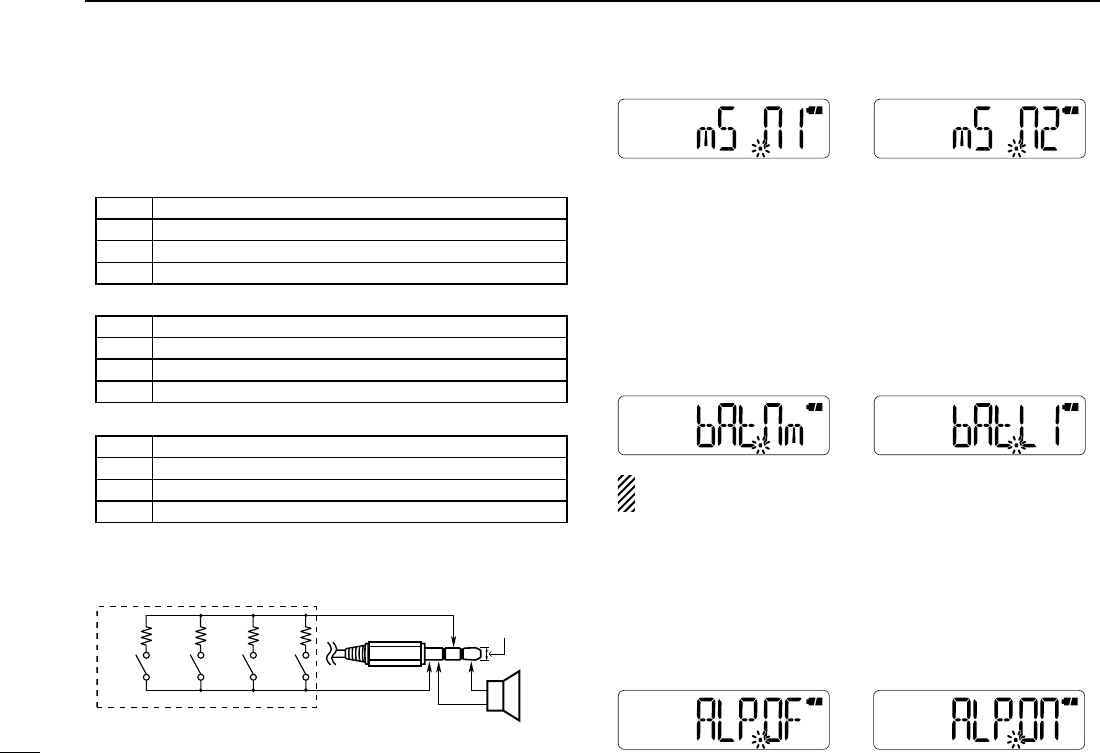
D Display type
Selects the display type for memory mode operation.
• dSP.FR : Displays the programmed frequency. (default)
• dSP.CH :
Displays the memory channel number. Operable func-
tions, configurable items in the Set mode, and select-
able modes will be restricted.
• dSP.nm :
Displays the channel name. If no memory name is pro-
grammed, the programmed frequency will be displayed.
D LCD contrast
Selects the LCD contrast.
• Lcd.LO : Sets the contrast to low.
• Lcd.At : Sets the contrast to high. However, if the transceiver is
exposed to high temperatures, it automatically sets the
contrast to low. (default)
D Power save
The power save function allows you conserve battery life by
selecting the duty cycle of the receiver. Select the ratio of the
power save time to the standby time.
To turn the function OFF, select “P–S.OF.”
• P–S.OF : Turns the function OFF.
• P–S. 2 : Sets the duty cycle to 1:2.
• P–S. 8 : Sets the duty cycle to 1:8.
• P–S.16 : Sets the duty cycle to 1:16.
• P–S.At : Automatically sets the duty cycle. (default)
D Select speed
The tuning speed acceleration automatically speeds up the
tuning speed when rotating [VOL] rapidly.
• S–S. m : Turns the tuning speed acceleration OFF.
• S–S. At : Turns the tuning speed acceleration ON. (default)
1
2
3
4
5
6
7
8
9
11
12
13
14
15
16
17
18
19
47
10 SET MODES
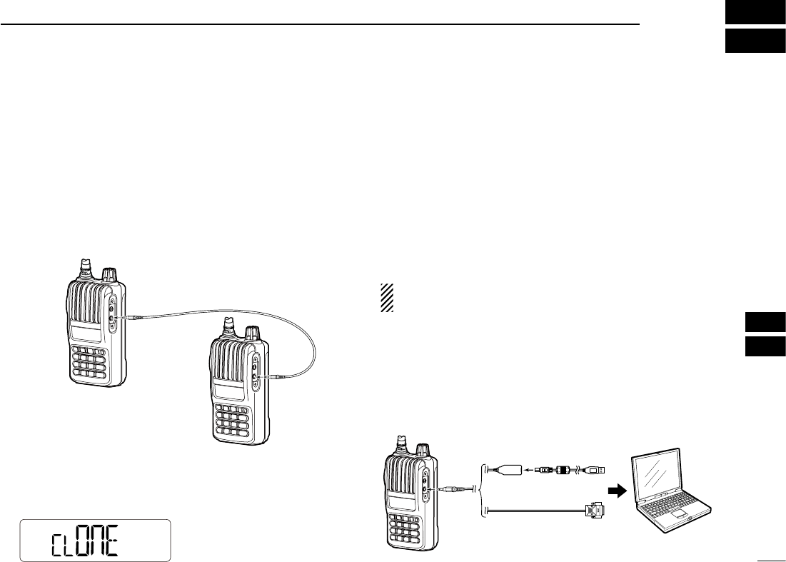
D Microphone simple mode
Microphone simple mode is used to assign the essential opera-
tions to the four switches (S1 to S4) on the remote control unit.
• mS .Sm
• mS .n1 (default)
• mS .n2
• User remote control unit
The below circuit is for reference only.
D Battery protection
When the battery voltage decreases, the battery protection
function automatically turns the transceiver OFF. Select the
function according to your battery type.
(default: differs depending on the version)
• bAt.OF : Turns the function OFF. Select when you use the
BP-263 battery case.
• bAt.nm : Select when you use the BP-264 Ni-MH battery pack.
• bAt.LI : Select when you use the BP-265 Li-Ion battery pack.
NOTE: BE SURE to select an appropriate option accord-
ing to your battery type
.
D Auto low power
Turns the auto low power function ON or OFF.
When the temperature goes below 0°C (+32°F), the function
automatically sets the output power to low.
In that case, the transmit power selections (Hi/Mid) are also
disabled. (default: ALP.OF)
2.7kW6.8kW15kW33kW
+
–
S1 S2 S3 S4
to the [SP] jack
GND
SP
REMOTE
Rated input 700 mW (8 W)
EXTERNAL SPEAKER
3.5(d) mm
>
‗
S1 Selects the Call channel.
S2 Turns the monitor function ON or OFF.
S3 Selects memory channel 0.
S4 Selects memory channel 1.
S1 Toggles the VFO mode and the memory mode.
S2 Selects the Call channel.
S3 Frequency or memory channel “UP.”
S4 Frequency or memory channel “DOWN.”
S1 Toggles the VFO mode and the memory mode.
S2 Turns the monitor function ON or OFF.
S3 Frequency or memory channel “UP.”
S4 Frequency or memory channel “DOWN.”
48
10
11
11
CLONING
■ Cloning operation
Cloning allows you to quickly and easily transfer the
programmed contents from one transceiver to another.
D Transceiver-to-transceiver cloning
q Turn the transceiver’s power OFF, and then connect an
optional OPC-474 cloning cable to the [SP] jacks of the
master transceiver and the sub transceiver.
• The master transceiver is used to send data to the sub trans-
ceiver.
w While pushing [FUNC](M) and [], turn the master trans-
ceiver ON to enter the cloning mode.
• “CLONE” appears
e Turn the sub transceiver ON.
r Push [PTT] on the master transceiver.
• “CL Out” appears on the master transceiver’s display, and the
signal indicator shows the data is being transferred to the sub
transceiver.
• “CL In” appears on the sub transceiver’s display, and the signal
indicator shows the data is being received from the master
transceiver.
t
When cloning is finished, turn both the transceivers OFF.
Then turn them ON again to exit the cloning mode.
NOTE: DO NOT push [PTT] on the sub transceiver dur-
ing cloning. This will cause a cloning error.
D Cloning using a PC
The CS-V80 cloning software is also used to clone/edit con-
tents with a PC (for Microsoft® Windows® 2000/XP or Win-
dows Vista®) using ICF format files.
Refer to the INSTRUCTIONS and the Help file that come
with the CS-V80, for details.
Master transceiver
Sub transceiver
Transceiver
PC
OPC-478
(RS-232C type)
OPC-478UC
(USB type) to USB port
to RS-232C
port
1
3
4
2
5
6
7
8
9
12
13
14
15
16
17
18
19
49
RESETTING
12
■ Resetting
The LCD may occasionally display erroneous infor-
mation (e.g. when first applying power). This may be
caused externally by static electricity or by other factors.
If this problem occurs, turn power OFF. After waiting a
few seconds, turn power ON again. If the problem per-
sists, perform either or both of the procedures below.
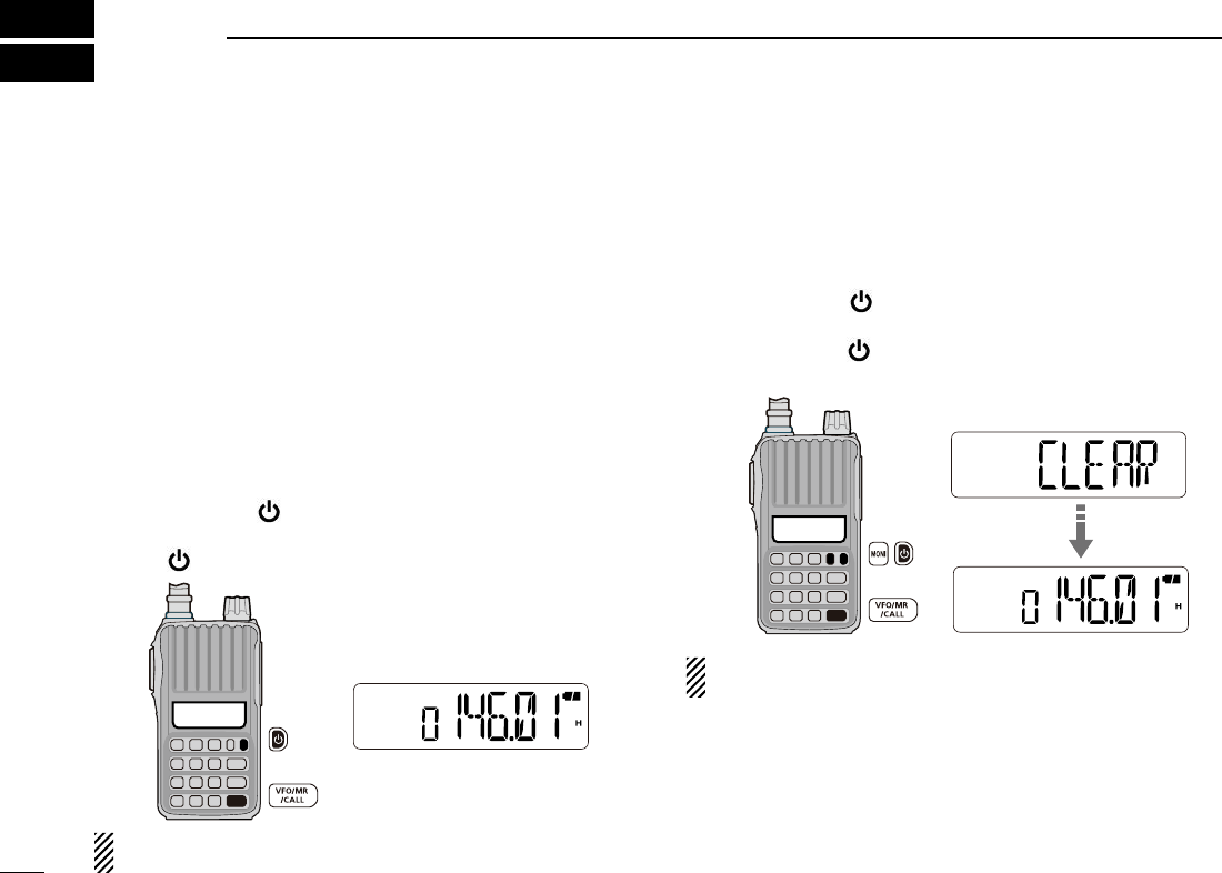
D Partial reset
If you want to reset the operating conditions (VFO fre-
quency, VFO settings, and Set modes contents) with-
out clearing the memory contents, use the partial reset.
q Push and hold [ ] for 1 sec. to turn the power OFF.
w While pushing and holding [VFO/MR/CALL], push and
hold [ ] for 1 sec. to turn the power ON.
NOTE: No message appears on the display after the par-
tial reset is done.
D All reset
The all reset clears all programming and returns all
settings to their factory defaults.
q Push and hold [ ] for 1 sec. to turn the power OFF.
w While pushing and holding [MONI] and [VFO/MR/CALL],
push and hold [ ] for 1 sec. to turn the power ON.
• “CLEAR” appears when resetting the CPU.
CAUTION: The all reset returns all programmed contents
to their default settings.
50
12
13
13
TROUBLE SHOOTING
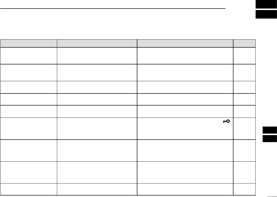
If your transceiver seems to be malfunctioning, please check the following points before sending it to a service center.
PROBLEM POSSIBLE CAUSE SOLUTION REF.
The transceiver does not turn
ON.
• The battery is exhausted.
• The battery polarity is reversed.
• Loose connection of a battery pack/case.
• Charge the battery pack, or replace the batteries.
• Check the battery polarity.
• Clean battery terminals.
pp. 11–13
p. 13
p. 13
No sound comes from the
speaker.
• Volume is too low.
• An external speaker or a cloning cable is
connected to the [SP] jack.
• Rotate [VOL] to adjust to a desired level.
• Check the external speaker connection or remove
the cloning cable.
p. 14
–
Transmitting is impossible. • The battery is exhausted.
• TX permission is inhibited.
• Charge the battery pack, or replace the batteries.
•
Set the TX permission setting to “ON” in the Set mode.
pp. 11–13
p. 41
Transmitting using the VOX
function is impossible.
• The VOX gain is set to OFF or too low.
• The microphone gain is too low.
•
Set the VOX gain to a suitable level.
•
Set the microphone gain to a suitable level.
pp. 41, 53
p. 41
Contacting with another sta-
tion is impossible.
• A different tone or code is used for the
tone/DTCS squelch.
• Check the tone/DTCS by performing a tone scan. p. 34
Frequency cannot be set. • The key lock function is activated.
• The memory mode, Call channel mode, or
weather channel mode is selected.
• Push [FUNC](M), then push and hold [ ]
(# ENT) for 1 sec. to cancel the key lock function.
• Push [VFO/MR/CALL] several times to select the
VFO mode.
p. 18
p. 15
A programmed scan does not
start.
• The memory mode, Call channel mode, or
weather channel mode is selected.
• The same frequency has been programmed
in the scan edge channels, “XA”–“Xb.”
• Push [VFO/MR/CALL] several times to select the
VFO mode.
• Program different frequencies in the scan edge
channels.
p. 15
p. 25
A memory scan does not
start.
• The VFO mode or Call channel mode is
selected.
• Only one or no memory channel has been
programmed.
• Push [VFO/MR/CALL] several times to select the
memory mode.
• Program 2 or more memory channels.
p. 15
p. 25
The displayed frequency is er-
roneous.
• The CPU has malfunctioned.
• External factors have caused a fault.
• Reset the transceiver.
• Remove and re-attach the battery pack/case.
p. 49
p. 2
1
2
3
4
5
6
7
8
9
10
11
14
15
16
17
18
19

51
OPTIONS
14
• BP-263 battery case
Battery case for LR6 (AA) × 6 alkaline batteries.
• BP-264 ni-mh battery pack
7.2 V/1400 mAh (Typ.) Ni-MH battery pack. Battery life: 13 hrs.
(approx.; FM, high power, Tx : Rx : Standby = 5:5:90)
• BP-265 li-ion battery pack
7.4 V/1900 mAh (Min.)/2000 mAh (Typ.) Lithium Ion battery
pack. Battery life: 19 hrs. (approx.; FM, high power, Tx : Rx :
Standby = 5:5:90)
• BC-191 desktop charger+BC-123S ac adapter
For rapid charging of the Ni-MH battery pack. An AC adapter
may be supplied with the charger, depending on the version.
Charging time: approx. 2 hours for the BP-264.
• BC-192 desktop charger+BC-147S ac adapter
For regular charging of the Ni-MH battery pack. An AC adapter
may be supplied with the charger, depending on the version.
Charging time: approx. 16 hours for the BP-264.
• BC-193 desktop charger+BC-123S ac adapter
For rapid charging of the Li-Ion battery pack. An AC adapter
may be supplied with the charger, depending on the version.
Charging time: approx. 2.5 hours for the BP-265.
• CP-23L cigarette lighter cable
Allows charging of the battery packs through a 12 V cigarette
lighter socket. (For only BC-191/BC-193)
• OPC-515L dc power cable
Allows charging of the battery packs using a 12 V DC power
source instead of the AC adapter. (For all chargers)
• MB-124 belt clip
Exclusive alligator-type belt clip.
• FA-B2E vhf antenna
The same antenna that is supplied with the transceiver.
• HM-153L earphone-mirophone
Ideal for hands-free operation: clip the HM-153L (with inte-
grated PTT switch) to your lapel or breast pocket.
• HM-158L/HM-159L speaker-mirophone
Combination speaker-microphone that provides convenient
operation while hanging the transceiver on your belt.
•
HS-94/HS-95/HS-97 headset+OPC-2004 plug adapter cable
HS-94 : Ear hook type
HS-95 : Neck & arm type
HS-97 : Throat microphone
OPC-2004 : Allows you to connect the HS-94/HS-95/HS-97 to
the transceiver. After connecting, the VOX function
can be used.
•
CS-V80
cloning software+
OPC-478
/
OPC-478UC
cloning cable
Provides quick and easy programming of such settings as
memory channels and Set modes contents.
• OPC-474 cloning cable
For transceiver-to-transceiver cloning.
Some options may not be available in some countries. Please
ask your dealer for details.
52
14
14
OPTIONS
■ VOX function
The transceiver has a VOX function, which allows hands-free
operation.
An optional HS-94, HS-95 or HS-97 headset and the
OPC-2004 plug adapter cable are also required for operation.
• The VOX (voice operated transmission) function starts transmis-
sion when you speak into the microphone, without needing to
push [PTT]; then, automatically returns to reception when you stop
speaking.
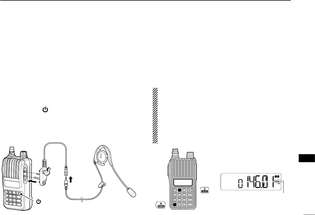
D Optional unit connection
q Push and hold [ ] for 1 sec. to turn the power OFF.
w Remove the jack cover. (p. 2)
e Connect the optional HS-94, HS-95 or HS-97 and
OPC-2004, as illustrated below.
D Turning the VOX function ON or OFF
q Connect an optional headset and plug adapter cable to
the transceiver, and then turn the power ON.
w Push
[FUNC](M), and then [VOX](2)
to turn the VOX func-
tion ON or OFF
.
•
“VOX” appears when the VOX function is ON.
NOTE:
• When using the VOX function, adjust the microphone gain
and the VOX-related settings (p. 53) to suit your operating
environment (including your headset performance).
• Set the microphone gain before setting the VOX gain in
the Set mode (p. 41). We recommend setting the micro-
phone gain to 3.
•
When the TX permission is set to “OFF” in the Set mode,
you cannot transmit using the VOX function. (p. 41)
HS-94OPC-2004
q
w
e
[ ]
Appears
1
3
2
4
5
6
7
8
9
10
11
12
13
15
16
17
18
19
53
D VOX-related settings
The VOX gain, the VOX delay, and the VOX time-out timer can
be set in the Set mode.
q Connect an optional headset and plug adapter cable to
the transceiver, and then turn the power ON.
w Push [FUNC](M), and then [VOX](2) to turn the VOX func-
tion ON.
e Push [FUNC](M), and then [SET](8) to enter the Set mode.
r Push [] or [] to select the VOX gain (VOX), the VOX
delay (VXd), or the VOX time-out timer (Vto) item.
t Rotate [VOL] to select a desired option.
y Push [# ENT] to exit the Set mode.
The VOX function does not activate transmission while in
the Set mode.
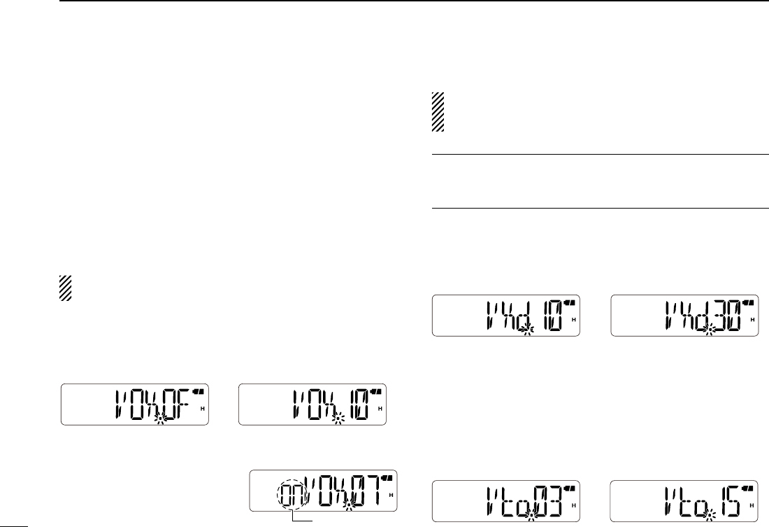
• VOX gain
The VOX gain level can be adjusted between 1 (minimum) and
10 (maximum), or turned OFF. Higher values make the VOX
function more sensitive to your voice.
(default: VOX.05)
➥ While speaking into the head-
set microphone, adjust the
VOX gain until “On” continu-
ously appears on the LCD.
If “On” is intermittent, be sure the VOX delay is set long
enough to allow normal pauses in speech, but keep the
VOX ON until you finish speaking.
✔ CONVENIENT!
While transmitting using the VOX function, you can adjust
the VOX gain simply by rotating [DIAL].
• VOX delay
Sets the VOX delay to between 0.5 and 3.0 sec. (in 0.5 sec.
steps). The VOX delay is the amount of time the transmitter
stays ON after you stop speaking. (default: VXd.10)
The VOX delay is set to
1 sec.
The VOX delay is set to
3 sec.
• VOX time-out timer
Sets the VOX time-out timer to between 1, 2, 3, 4, 5, 10 and
15 min. to prevent accidental prolonged transmission for the
VOX function.
To turn the function OFF, select “Vto.OF.” (default: Vto.03)
14 OPTIONS
The VOX function is
turned OFF.
The VOX gain is set to
10 (maximum).
Appears
54
14
15
9
15
SPECIFICATIONS
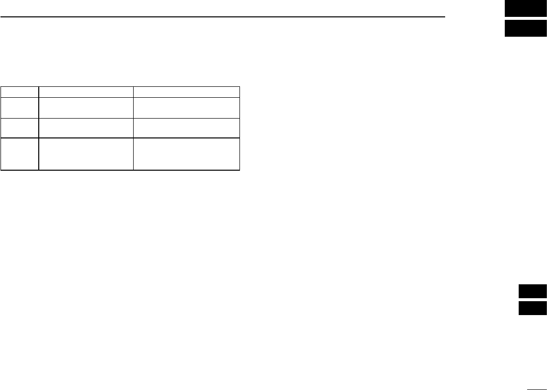
D General
• Frequency coverage : (unit: MHz)
Version TX RX
U.S.A.
AUS 144–148 136–174
CHN
EXP 136–174 136–174
EUR
UK
KOR
144–146 144–146
• Mode :
FM, FM-N
• Number of memory channels : 207
(incl. 6 scan edges and 1 Call channel)
• Usable temperature range : –20°C to +60°C; –4°F to +140°F
• Tuning steps : 5,
10,
12.5,
15,
20,
25,
30
and
50 kHz
• Frequency stability : ±2.5 ppm
(–20°C to +60°C; –4°F to +140°F)
• Power supply : Icom specified battery pack/case
• Current drain (at 7.2 V DC: typical)
Transmit at 5.5 W (High) : 1.4 A
at 2.5 W (Mid.) 0.9 A
at 0.5 W (Low) 0.6 A
Receive standby : 65 mA
power save 20 mA
max. audio
310 mA
(internal speaker)
180mA
(external speaker)
• Antenna connector : BNC (50 W)
• Dimensions : 58(W)×112(H)×30(D) mm;
(projections not included) 29⁄32(W)×413⁄32(H)×13⁄16(D) in
• Weight (approx.)
(without battery pack/case and ant.) : 140 g; 4.9 oz
D Transmitter
• Modulation system : Variable reactance freq. modulation
• Output power (at 7.2 V DC) : High 5.5 W, Mid. 2.5 W, Low 0.5 W.
• Max. frequency deviation : FM (wide) ±5.0 kHz
FM (narrow) ±2.5 kHz
• Spurious emissions : Less than –60 dBc
• External mic. connector :
3-conductor 2.5 (d) mm (
1⁄10
˝)/2.2 kΩ
D Receiver
• Receive system :
Double-conversion superheterodyne
• Intermediate frequencies : 1st: 21.7 MHz, 2nd: 450 kHz
• Sensitivity (at 12 dB SINAD) : –0.14 μV typ.
• Squelch sensitivity (threshold) : –0.1 μV typ.
• Selectivity : FM (wide) 70 dB typ.
FM (narrow) 50 dB typ.
•
Spurious and image rejection
: 75 dB typ.
• Intermodulation : FM (wide) 70 dB typ.
FM (narrow) 65 dB typ.
• Audio output power (at 10% distortion)
Internal speaker : 0.75 W typ. with a 16 Ω load
External speaker : 0.45 W typ. with a 8 Ω load
• External speaker connector : 3-conductor 3.5(d) mm; (1⁄8˝)/8 Ω
All stated specifications are subject to change without notice or
obligation.
1
2
3
4
5
6
7
8
10
11
12
13
16
17
18
19
55
CE
16
IMPORTANT
• When transmitting with a portable radio, hold the radio in
a vertical position with its microphone 2.5 to 5 centimetres
from your head and body.
• If you wear a portable two-way radio on your body, ensure
that the antenna is at least 2.5 centimetres from your body
when transmitting.
CE Versions of the IC-V80E which display
the ‘CE’ symbol on the serial number label,
comply with the essential requirements of the
European Radio and Telecommunication Ter-
minal Directive 1999/5/EC.
This warning symbol indicates that this equip-
ment operates in non-harmonised frequency
bands and/or may be subject to licensing con-
ditions in the country of use. Be sure to check
that you have the correct version of this radio
or the correct programming of this radio, to
comply with national licensing requirements.
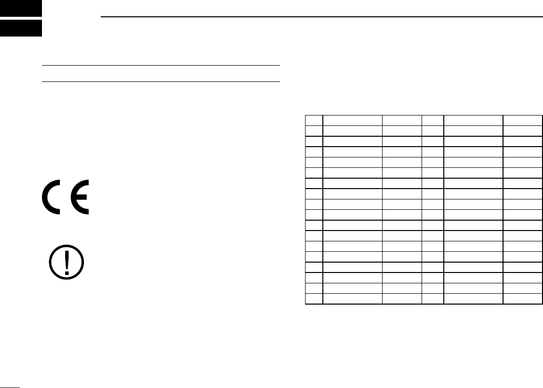
• List of Country codes (ISO 3166-1)
Country Codes Country Codes
1 Austria AT 18 Liechtenstein LI
2 Belgium BE 19 Lithuania LT
3 Bulgaria BG 20 Luxembourg LU
4 Croatia HR 21 Malta MT
5 Czech Republic CZ 22 Netherlands NL
6 Cyprus CY 23 Norway NO
7 Denmark DK 24 Poland PL
8 Estonia EE 25 Portugal PT
9 Finland FI 26 Romania RO
10 France FR 27 Slovakia SK
11 Germany DE 28 Slovenia SI
12 Greece GR 29 Spain EP
13 Hungary HU 30 Sweden SE
14 Iceland IS 31 Switzerland CH
15 Ireland IE 32 Turkey TR
16 Italy IT 33 United Kingdom GB
17 Latvia LV
56
16
16
CE
Düsseldorf
16th Oct.
2009
Place and date of issue
Icom (Europe) GmbH
Himmelgeister straße 100
D-40225 Düsseldorf
Authorized representative name
Y. Furukawa
General Manager
Signature
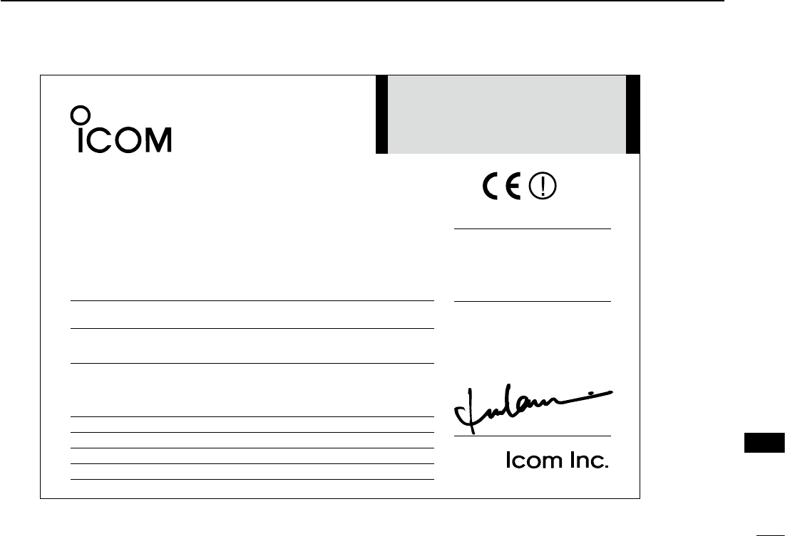
DECLARATION
OF CONFORMITY
We Icom Inc. Japan
1-1-32, Kamiminami, Hirano-ku
Osaka 547-0003, Japan
Declare on our sole responsibility that this equipment complies with the
essential requirements of the Radio and Telecommunications Terminal
Equipment Directive, 1999/5/EC, and that any applicable Essential Test
Suite measurements have been performed.
Kind of equipment: VHF TRANSCEIVER
Type-designation: iV80E
Version (where applicable):
desinomrah gniwollof eht htiw ytimrofnoc no desab si ecnailpmoc sihT
standards, specifications or documents:
i) EN 301 489-1 v1.8.1 (Apr. 2008)
ii) EN 301 489-15 v1.2.1 (Aug. 2002)
iii) EN 301 783-2 v1.1.1 (Sep. 2000)
iv) EN 60950-1 (2001): A11: 2004
1
2
3
4
5
6
7
8
9
10
11
12
13
15
14
17
18
19
1-1-32 Kamiminami, Hirano-ku, Osaka 547-0003, Japan
A-6795H-1EX-0a
Printed in Japan
© 2009 Icom Inc.
Printed on recycled paper with soy ink.
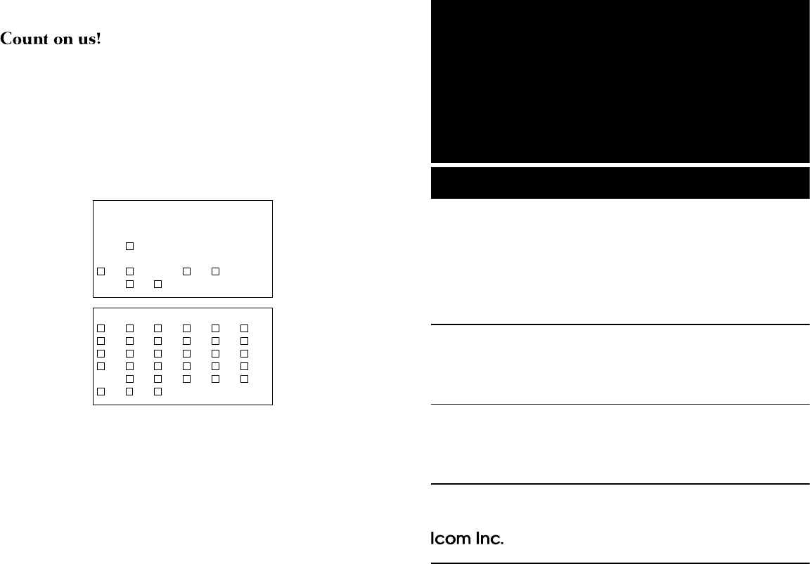
<Intended Country of Use>
■ AT ■ BE ■ CY ■ CZ ■ DK ■ EE
■ FI ■ FR ■ DE ■ GR ■ HU ■ IE
■ IT ■ LV ■ LT ■ LU ■ MT ■ NL
■ PL ■ PT ■ SK ■ SI ■ ES ■ SE
■ GB ■ IS ■ LI ■ NO ■ CH ■ BG
■ RO ■ TR ■ HR
#02 Europe
#12 Europe-21
#22 Europe-22
#32 Europe-23
<Intended Country of Use>
■ AT ■ BE ■ CY ■ CZ ■ DK ■ EE
■ FI ■ FR ■ DE ■ GR ■ HU ■ IE
■ IT ■ LV ■ LT ■ LU ■ MT ■ NL
■ PL ■ PT ■ SK ■ SI ■ ES ■ SE
■ GB ■ IS ■ LI ■ NO ■ CH ■ BG
■
RO ■ TR ■ HR
#13 U.K.-01
#23 U.K.-02
#33 U.K.-03