ICOM orporated 325400 VHF Transceiver User Manual 2
ICOM Incorporated VHF Transceiver 2
UserManual.wiki
>
ICOM orporated
>
325400 User Manual
>
User Manual 2
Contents
1.
User Manual 1
2.
User Manual 2
User Manual 2
Navigation menu
Upload a User Manual
Namespaces
Wiki Guide
HTML
PDF
Info
Views
User Manual
Discussion / Help
Navigation
, and then [PRIO](7) to start the watch.• The decimal point “.”, on the frequency readout blinks.• When a signal is detected on the channel, the watch resumes according to the scan resume setting. (p. 30)e To cancel the watch, push any key except [ ], []/[], [MONI], [FUNC](M), or [PTT].D Memory scan watchWhile operating on a VFO frequency, a memory scan watch checks for signals on each memory channel in sequence, every 5 sec. q Push [VFO/MR/CALL] several times to select the memory mode.w Push [FUNC](M), and then [SCAN](5) to start a memory scan.e Push [FUNC](M), and then [PRIO](7) to start the watch.• The VFO mode is selected, and the decimal point “.”, on the fre-quency readout blinks.• When a signal is detected on a channel, the watch resumes ac-cording to the scan resume setting. (p. 30)r To cancel the watch, push any key except [ ], []/[], [MONI], [FUNC](M), or [PTT].Memory channelVFO frequency5 sec.VFO frequency5 sec.Memory scanMch 0Mch 1Mch 2Mch 199SKIP7SCAN OPERATION](https://usermanual.wiki/ICOM-orporated/325400.User-Manual-2/User-Guide-1203027-Page-1.png)
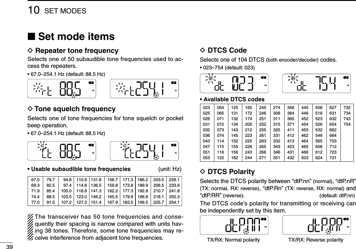
, and then [SET](8) to enter the Set mode.w Push [] or [] to select the CTCSS tone item (Ct) or the DTCS code item (dt).• “ ” blinks when selecting the CTCSS tone item, and “D” blinks when selecting the DTCS code item.e Rotate [VOL] to select a desired CTCSS tone or DTCS code.• The recommended CTCSS tone or DTCS code are shown to the left. r Push [# ENT] to exit the Set mode.■ Tone/DTCS squelch and pocket beep023025026031032043047051054065071072073074114115116125131132134143152155156162165172174205223226243244245251261263265271306311315331343346351364365371411412413423431432445464465466503506516532546565606612624627631632654662664703712723731732734743754DTCS code settingCTCSS tone setting[VOL] 123456910111213141516171819](https://usermanual.wiki/ICOM-orporated/325400.User-Manual-2/User-Guide-1203027-Page-2.png)
, and then [SET](8) to enter the Set mode.w Push [] or [] to select the DTCS polarity item (dtP).e Rotate [VOL] to select a desired polarity setting between “dtP.nn” (normal), “dtP.nR” (TX: normal, RX: reverse), “dtP.Rn” (TX: reverse, RX: normal) and “dtP.RR” (reverse).r Push [# ENT] to exit the Set mode.D Operationq Set a desired operating frequency, and then a CTCSS tone or a DTCS code.w Push [FUNC](M), and then [TONE](1).• Repeat step w several times to activate a desired tone function.e Operate the transceiver in a normal way.8TONE SQUELCH AND POCKET BEEPTX/RX: Normal polarity TX: Normal, RX: Reverse TX: Reverse, RX: Normal TX/RX: Reverse polarity Function OFFPush , and then to select the tone function in sequence.Tone squelch withpocket beepTone squelchDTCS squelchDTCS squelch withpocket beepRepeater tone](https://usermanual.wiki/ICOM-orporated/325400.User-Manual-2/User-Guide-1203027-Page-3.png)
![348r When receiving a signal that includes a matched tone or code, the squelch opens and the signal can be heard. When the pocket beep function is activated.• Beep tones sound and “ ” blinks. To stop the beeps and blink-ing, push any key.• When the received signal’s tone/code does not match, the squelch does not open. However, the signal indicator shows the signal strength.• To open the squelch manually, push and hold [MONI].t Push [PTT] to answer.■ Tone scanBy monitoring a signal from a repeater, pocket beep or squelch function operation, you can determine the subaudi-ble tone required to access the repeater or open the squelch.q Set a frequency to be checked for a tone frequency or DTCS code.w Push [FUNC](M), and then [TONE](1).• Repeat step w several times to activate a desired tone function.• The tone scan can be made even if the tone function is not se-lected.e Push [FUNC](M), and then [T.SCAN](3) to start a tone scan.• To change the scan direction, push [] or [].r When a tone frequency or DTCS code is matched, the squelch opens and the tone frequency or code is tempo-rarily programmed into the selected mode.• When a tone frequency or DTCS code is detected, the tone scan pauses according to the scan resume setting (p. 30)• The decoded CTCSS tone frequency or DTCS code is used ac-cording to the selected tone function type in step w.- No indication : Cannot be used for operation.-“ ” : CTCSS tone encoder (repeater tone)-“ ” : CTCSS tone encoder/decoder-“D” : DTCS tone encoder/decodert To cancel the scan, push any key except [ ], []/[], [MONI] or [FUNC](M).8TONE SQUELCH AND POCKET BEEP1234567910111213141516171819](https://usermanual.wiki/ICOM-orporated/325400.User-Manual-2/User-Guide-1203027-Page-4.png)
, and then [DTMF.M](0) to enter the DTMF memory mode.w Push [] or [] to select a desired DTMF memory chan-nel.• If programmed, the previously programmed DTMF code is dis-played.e Push [FUNC](M), and then push and hold [DTMF.M](0) for 1 sec. to enter the programming mode.• “_ _ _ _ _” appears.• Programmed memories will be cleared by this operation.r Push keys to input a desired DTMF code sequence of up to 24 digits.• [0]–[9] inputs “0”–“9,” [MONI] inputs “A,” [] inputs “B,” [] inputs “C,” [VFO/MR/CALL] inputs “D,” [M] inputs “M(E)” and [# ENT] inputs “# (F).”• If a digit is mistakenly input, push [PTT] momentarily, then re-peat from step e.t Repeat step r until the desired code is input.y Push [PTT] to store the DTMF code sequence and exit the programming mode.• After the 24th digit is input, the transceiver automatically stores the code sequence and returns to step w.u Push [VFO/MR/CALL] to exit the DTMF memory.• Programming mode indicationThe programming mode consists of 5 pages.Push , and then .Push , and then pushand hold for 1 sec. The next page appears whenthe 6th digit has been input.■ Programming a DTMF code sequenceDTMF MEMORY9Page Digits Indication1st 1st to 5th No indication.2nd 6th to 10th “ ” appears.3rd 11th to 15th “ ” appears.4th 16th to 20th “ ” appears.5th 21st to 24th “ ” blinks.](https://usermanual.wiki/ICOM-orporated/325400.User-Manual-2/User-Guide-1203027-Page-5.png)
, and then [SET](8) to enter the Set mode.w Push [] or [] to select the DTMF TX key item (dmt).e Rotate [VOL] to select a desired option.• dmt.k : Transmits the appropriate DTMF code assigned to the pushed key. • dmt.m : Transmits the programmed DTMF code sequence in the DTMF memory channel assigned to the pushed key.• dmt.t : No DTMF code can be transmitted. However, while pushing and holding [PTT], pushing either the [] or [] transmits a 1750 Hz tone burst signal.r Push [# ENT] to exit the Set mode.D Manual DTMF code transmissionFirst, set the DTMF TX key to “dmt.k” in the Set mode.➥ While pushing and holding [PTT], push the desired keys to transmit a DTMF code sequence manually.• Push [0]–[9] for “0”–“9,” [MONI] for “A,” [] for “B,” [] for “C,” [VFO/MR/CALL] for “D,” [M] for “M,” and [# ENT] for “#.”D Using a DTMF memory channel First, set the DTMF TX key to “dmt.m” in the Set mode.➥ While pushing and holding [PTT], push one of the keys to transmit the programmed DTMF code sequence in the DTMF memory.• Pushing [0] to [9], [MONI](A), [](B), [](C), [VFO/MR/CALL] (D), [M](E), or [# ENT](F) transmits a DTMF code channel (d0–d9, dA, dB, dC, dD, dE or dF) respectively.D 1750 Hz tone To access some European repeaters, the transceiver must transmit a 1750 Hz tone burst signal. • This tone can be used as a ‘Call signal’ in countries out of Europe.First, set the DTMF TX key to “dmt.t” in the Set mode.➥ While pushing and holding [PTT], push and hold either the [] or [] for 1 or 2 sec. to transmit a 1750 Hz tone burst signal.• While pushing and holding the key, the tone is transmitted.■ Transmitting a DTMF code sequence 1234567810111213141516171819](https://usermanual.wiki/ICOM-orporated/325400.User-Manual-2/User-Guide-1203027-Page-6.png)
, and then [DTMF.M](0) to enter the DTMF memory mode.w Push [] or [] to select a desired DTMF memory chan-nel.e Push [MONI] to confirm the DTMF memory contents.• The programmed DTMF code sequence sounds.• After sounding, the transceiver exits the DTMF memory mode. ■ Setting DTMF transfer speedWhen slow DTMF transmission speeds are required with DTMF memory transmission (as for some repeaters), the transceiver’s rate of DTMF transmission can be adjusted in the Initial Set mode.q While pushing and holding [] and [], turn the power ON to enter the Initial Set mode.w Push [] or [] to select the DTMF speed item. (dtd)e Rotate [VOL] to select a desired speed.• dtd. 1 : 100 msec. interval; 5.0 cps rate • dtd. 2 : 200 msec. interval; 2.5 cps rate• dtd. 3 : 300 msec. interval; 1.6 cps rate• dtd. 5 : 500 msec. interval; 1.0 cps rate (cps=characters per second)r Push [# ENT] to exit the Initial Set mode.Exits the DTMF memory mode. The programmed DTMF codesequence sounds.](https://usermanual.wiki/ICOM-orporated/325400.User-Manual-2/User-Guide-1203027-Page-7.png)
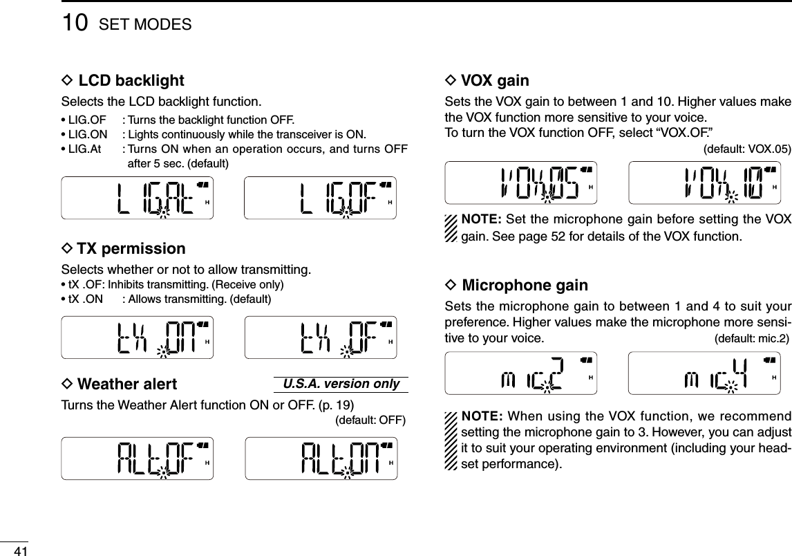
, and then [SET](8) to enter the Set mode.w Push [] or [] to select the desired item.e Rotate [VOL] to select the option or value.r To exit the Set mode, push [# ENT].• Repeater tone frequency (p. 39)• Tone squelch frequency (p. 39) • DTCS code (p. 39) • DTCS polarity (p. 39) • Frequency offset (p. 40)• Reverse duplex functon (p. 40)• Tuning step (p. 40)• Scan resume setting (p. 40)• Function key timer (p. 40)• LCD backlight (p. 41)• TX permission (p. 41)• VOX gain (p. 41)• Microphone gain (p. 41)• Weather alert* (p. 41)• VOX delay (p. 41)• VOX time-out timer (p. 42)• DTMF TX key (p. 42)• Operating mode (p. 42) *Appears for only the U.S.A. version transceivers.: Push: PushNOTE: When the display type setting (pp. 27, 46) is set to “CH” in the Initial Set mode, and accessing the Set mode from the memory mode, most of Set mode items do not appear.12435678111214131516171819](https://usermanual.wiki/ICOM-orporated/325400.User-Manual-2/User-Guide-1203027-Page-8.png)
 to enter the Function mode, and then push a keypad key to activate it’s second function.• During the Function mode, “ ” is displayed on the LCD.Set the time between when Function mode is entered, and how long it remains activated after you push the keypad key to activate it’s second function. • F0.At : Exits the Function mode immediately after a key is pushed to activate it’s second function. (default)• F1/2/3.At : The Function mode remains activated for the selected pe-riod after a key is pushed to activate it’s second function.• F .m : The Function mode remains activated until [FUNC](M) is pushed again, even after a key is pushed to activate it’s second function.123456789111213141516171819](https://usermanual.wiki/ICOM-orporated/325400.User-Manual-2/User-Guide-1203027-Page-10.png)
![421010SET MODESD VOX delaySets the VOX Delay to between “VXd.05” (0.5 sec.), “VXd.10” (1 sec.), “VXd.15” (1.5 sec.), “VXd.20” (2 sec.), “VXd.25” (2.5 sec.) and “VXd.30” (3 sec.). The VOX Delay is the amount of time the transmitter stays ON after you stop speaking. (default: VXd.10)D VOX time-out timerSets the VOX time-out timer to between 1, 2, 3, 4, 5, 10 and 15 min. to prevent accidental prolonged transmission for the VOX function.To turn the function OFF, select “Vto.OF.” (default: Vto.03)D DTMF TX keySelects the method to transmit a DTMF code sequence. While pushing and holding [PTT], push one of the keys, [0] to [9], [MONI](A), [](B), [](C), [VFO/MR/CALL](D), [M](E),and [# ENT](F).• dmt.k : Transmits the appropriate DTMF code assigned to the key. (default)• dmt.m : Transmits the programmed DTMF code sequence in the DTMF memory channel assigned to the key.• dmt.t : No DTMF code can be transmitted. However, while pushing and holding [PTT], push either the [] or [] to transmit a 1750 Hz tone burst signal.D Operating modeSet the operating mode to FM or FM-N. The operating mode is determined by the modulation of the radio signals. (default: W/n. W)FM mode FM-N mode123456789111213141516171819](https://usermanual.wiki/ICOM-orporated/325400.User-Manual-2/User-Guide-1203027-Page-12.png)
![4310 SET MODES■ Initial Set mode programmingThe Initial Set mode can be accessed at power ON and al-lows you to set seldom-changed settings, to suit your prefer-ence and operating style. D Initial Set mode operationq While pushing and holding [] and [], turn the power ON to enter the Initial Set mode.w Push [] or [] to select the desired item.e Rotate [VOL] to select the option or value.r To exit the Initial Set mode, push [# ENT].• Time-out timer (p. 44) • Auto repeater* (p. 44) • Auto power-OFF (p. 44) • Lockout (p. 45)• Squelch delay (p. 45)• DTMF speed (p. 45)• Dial assignment (p. 45)• Display type (p. 46)• Power save (p. 46)• Select speed (p. 46) • LCD contrast (p. 46)• Battery protection function (p. 47)• Microphone simple mode (p. 47)• Key-touch beep (p. 44)• Auto low power (p. 47)*Appears for only the U.S.A. version transceivers.: Push: Push](https://usermanual.wiki/ICOM-orporated/325400.User-Manual-2/User-Guide-1203027-Page-13.png)
![4510 SET MODESD LockoutSelects the lockout type between repeater, busy and OFF.• RLO.OF : Turns the function OFF (default).• RLO.RP : The repeater lockout function inhibits transmitting when the channel is busy, except while receiving a signal that includes a matched tone.• RLO.bU : The busy lockout function inhibits transmitting while re-ceiving a signal.D Squelch delaySets the squelch delay between short and long. The delay prevents the squelch from repeatedly opening and closing while receiving the same signal.• Sqd. S : Sets the squelch delay to short (default).• Sqd. L : Sets the squelch delay to long.D DTMF speedSelects a desired DTMF transfer speed.• dtd. 1 : 100 msec. interval; 5.0 cps rate (default)• dtd. 2 : 200 msec. interval; 2.5 cps rate• dtd. 3 : 300 msec. interval; 1.6 cps rate• dtd. 5 : 500 msec. interval; 1.0 cps rate (cps=characters per second)D Dial assignmentSelects whether or not to use [VOL] as a tuning control in-stead of [] and []. When [VOL] functions as a tuning con-trol, [] and [] function as volume controls.• tOP.VO : Audio volume control (default)• tOP.dI : Tuning dial [VOL] and []/[] function as described below, depend-ing on the option.Option [VOL] []/[]tOP.VO Volume control Tuning controlstOP.di Tuning control Volume controls](https://usermanual.wiki/ICOM-orporated/325400.User-Manual-2/User-Guide-1203027-Page-15.png)
![461010SET MODESD Display typeSelects the display type for memory mode operation.• dSP.FR : Displays the programmed frequency. (default)• dSP.CH : Displays the memory channel number. Operable func-tions, configurable items in the Set mode, and select-able modes will be restricted.• dSP.nm : Displays the channel name. If no memory name is pro-grammed, the programmed frequency will be displayed.D LCD contrastSelects the LCD contrast.• Lcd.LO : Sets the contrast to low.• Lcd.At : Sets the contrast to high. However, if the transceiver is exposed to high temperatures, it automatically sets the contrast to low. (default)D Power saveThe power save function allows you conserve battery life by selecting the duty cycle of the receiver. Select the ratio of the power save time to the standby time.To turn the function OFF, select “P–S.OF.”• P–S.OF : Turns the function OFF.• P–S. 2 : Sets the duty cycle to 1:2.• P–S. 8 : Sets the duty cycle to 1:8.• P–S.16 : Sets the duty cycle to 1:16.• P–S.At : Automatically sets the duty cycle. (default)D Select speedThe tuning speed acceleration automatically speeds up the tuning speed when rotating [VOL] rapidly.• S–S. m : Turns the tuning speed acceleration OFF.• S–S. At : Turns the tuning speed acceleration ON. (default)123456789111213141516171819](https://usermanual.wiki/ICOM-orporated/325400.User-Manual-2/User-Guide-1203027-Page-16.png)
![4710 SET MODESD Microphone simple mode Microphone simple mode is used to assign the essential opera-tions to the four switches (S1 to S4) on the remote control unit.• mS .Sm• mS .n1 (default)• mS .n2 • User remote control unitThe below circuit is for reference only.D Battery protection When the battery voltage decreases, the battery protection function automatically turns the transceiver OFF. Select the function according to your battery type. (default: differs depending on the version)• bAt.OF : Turns the function OFF. Select when you use the BP-263 battery case.• bAt.nm : Select when you use the BP-264 Ni-MH battery pack. • bAt.LI : Select when you use the BP-265 Li-Ion battery pack. NOTE: BE SURE to select an appropriate option accord-ing to your battery type.D Auto low power Turns the auto low power function ON or OFF.When the temperature goes below 0°C (+32°F), the function automatically sets the output power to low.In that case, the transmit power selections (Hi/Mid) are also disabled. (default: ALP.OF)2.7kW6.8kW15kW33kW+–S1 S2 S3 S4to the [SP] jackGNDSPREMOTERated input 700 mW (8 W)EXTERNAL SPEAKER3.5(d) mm>‗S1 Selects the Call channel.S2 Turns the monitor function ON or OFF.S3 Selects memory channel 0.S4 Selects memory channel 1.S1 Toggles the VFO mode and the memory mode.S2 Selects the Call channel.S3 Frequency or memory channel “UP.”S4 Frequency or memory channel “DOWN.”S1 Toggles the VFO mode and the memory mode.S2 Turns the monitor function ON or OFF.S3 Frequency or memory channel “UP.”S4 Frequency or memory channel “DOWN.”](https://usermanual.wiki/ICOM-orporated/325400.User-Manual-2/User-Guide-1203027-Page-17.png)
![48101111CLONING■ Cloning operationCloning allows you to quickly and easily transfer the programmed contents from one transceiver to another.D Transceiver-to-transceiver cloningq Turn the transceiver’s power OFF, and then connect an optional OPC-474 cloning cable to the [SP] jacks of the master transceiver and the sub transceiver.• The master transceiver is used to send data to the sub trans-ceiver.w While pushing [FUNC](M) and [], turn the master trans-ceiver ON to enter the cloning mode.• “CLONE” appearse Turn the sub transceiver ON.r Push [PTT] on the master transceiver.• “CL Out” appears on the master transceiver’s display, and the signal indicator shows the data is being transferred to the sub transceiver.• “CL In” appears on the sub transceiver’s display, and the signal indicator shows the data is being received from the master transceiver.t When cloning is finished, turn both the transceivers OFF. Then turn them ON again to exit the cloning mode.NOTE: DO NOT push [PTT] on the sub transceiver dur-ing cloning. This will cause a cloning error.D Cloning using a PCThe CS-V80 cloning software is also used to clone/edit con-tents with a PC (for Microsoft® Windows® 2000/XP or Win-dows Vista®) using ICF format files.Refer to the INSTRUCTIONS and the Help file that come with the CS-V80, for details.Master transceiverSub transceiverTransceiverPCOPC-478(RS-232C type)OPC-478UC(USB type) to USB portto RS-232Cport1342567891213141516171819](https://usermanual.wiki/ICOM-orporated/325400.User-Manual-2/User-Guide-1203027-Page-18.png)
![49RESETTING12■ ResettingThe LCD may occasionally display erroneous infor-mation (e.g. when first applying power). This may be caused externally by static electricity or by other factors.If this problem occurs, turn power OFF. After waiting a few seconds, turn power ON again. If the problem per-sists, perform either or both of the procedures below.D Partial resetIf you want to reset the operating conditions (VFO fre-quency, VFO settings, and Set modes contents) with-out clearing the memory contents, use the partial reset.q Push and hold [ ] for 1 sec. to turn the power OFF.w While pushing and holding [VFO/MR/CALL], push and hold [ ] for 1 sec. to turn the power ON. NOTE: No message appears on the display after the par-tial reset is done.D All resetThe all reset clears all programming and returns all settings to their factory defaults.q Push and hold [ ] for 1 sec. to turn the power OFF.w While pushing and holding [MONI] and [VFO/MR/CALL], push and hold [ ] for 1 sec. to turn the power ON.• “CLEAR” appears when resetting the CPU. CAUTION: The all reset returns all programmed contents to their default settings.](https://usermanual.wiki/ICOM-orporated/325400.User-Manual-2/User-Guide-1203027-Page-19.png)
![50121313TROUBLE SHOOTINGIf your transceiver seems to be malfunctioning, please check the following points before sending it to a service center.PROBLEM POSSIBLE CAUSE SOLUTION REF.The transceiver does not turn ON.• The battery is exhausted.• The battery polarity is reversed.• Loose connection of a battery pack/case.• Charge the battery pack, or replace the batteries.• Check the battery polarity.• Clean battery terminals.pp. 11–13p. 13p. 13No sound comes from the speaker.• Volume is too low.• An external speaker or a cloning cable is connected to the [SP] jack.• Rotate [VOL] to adjust to a desired level.• Check the external speaker connection or remove the cloning cable.p. 14 –Transmitting is impossible. • The battery is exhausted.• TX permission is inhibited.• Charge the battery pack, or replace the batteries.• Set the TX permission setting to “ON” in the Set mode.pp. 11–13p. 41Transmitting using the VOX function is impossible.• The VOX gain is set to OFF or too low.• The microphone gain is too low.• Set the VOX gain to a suitable level.• Set the microphone gain to a suitable level.pp. 41, 53p. 41Contacting with another sta-tion is impossible.• A different tone or code is used for the tone/DTCS squelch.• Check the tone/DTCS by performing a tone scan. p. 34Frequency cannot be set. • The key lock function is activated.• The memory mode, Call channel mode, or weather channel mode is selected.• Push [FUNC](M), then push and hold [ ] (# ENT) for 1 sec. to cancel the key lock function.• Push [VFO/MR/CALL] several times to select the VFO mode.p. 18p. 15A programmed scan does not start.• The memory mode, Call channel mode, or weather channel mode is selected.• The same frequency has been programmed in the scan edge channels, “XA”–“Xb.”• Push [VFO/MR/CALL] several times to select the VFO mode.• Program different frequencies in the scan edge channels.p. 15p. 25A memory scan does not start.• The VFO mode or Call channel mode is selected.• Only one or no memory channel has been programmed.• Push [VFO/MR/CALL] several times to select the memory mode.• Program 2 or more memory channels.p. 15p. 25The displayed frequency is er-roneous.• The CPU has malfunctioned.• External factors have caused a fault.• Reset the transceiver.• Remove and re-attach the battery pack/case.p. 49p. 21234567891011141516171819](https://usermanual.wiki/ICOM-orporated/325400.User-Manual-2/User-Guide-1203027-Page-20.png)
![521414OPTIONS■ VOX functionThe transceiver has a VOX function, which allows hands-free operation.An optional HS-94, HS-95 or HS-97 headset and the OPC-2004 plug adapter cable are also required for operation.• The VOX (voice operated transmission) function starts transmis-sion when you speak into the microphone, without needing to push [PTT]; then, automatically returns to reception when you stop speaking.D Optional unit connectionq Push and hold [ ] for 1 sec. to turn the power OFF.w Remove the jack cover. (p. 2)e Connect the optional HS-94, HS-95 or HS-97 and OPC-2004, as illustrated below. D Turning the VOX function ON or OFFq Connect an optional headset and plug adapter cable to the transceiver, and then turn the power ON.w Push [FUNC](M), and then [VOX](2) to turn the VOX func-tion ON or OFF.• “VOX” appears when the VOX function is ON. NOTE: • When using the VOX function, adjust the microphone gain and the VOX-related settings (p. 53) to suit your operating environment (including your headset performance).• Set the microphone gain before setting the VOX gain in the Set mode (p. 41). We recommend setting the micro-phone gain to 3.• When the TX permission is set to “OFF” in the Set mode, you cannot transmit using the VOX function. (p. 41)HS-94OPC-2004qwe[ ]Appears132456789101112131516171819](https://usermanual.wiki/ICOM-orporated/325400.User-Manual-2/User-Guide-1203027-Page-22.png)
, and then [VOX](2) to turn the VOX func-tion ON.e Push [FUNC](M), and then [SET](8) to enter the Set mode.r Push [] or [] to select the VOX gain (VOX), the VOX delay (VXd), or the VOX time-out timer (Vto) item.t Rotate [VOL] to select a desired option.y Push [# ENT] to exit the Set mode.The VOX function does not activate transmission while in the Set mode.• VOX gainThe VOX gain level can be adjusted between 1 (minimum) and 10 (maximum), or turned OFF. Higher values make the VOX function more sensitive to your voice. (default: VOX.05)➥ While speaking into the head-set microphone, adjust the VOX gain until “On” continu-ously appears on the LCD.If “On” is intermittent, be sure the VOX delay is set long enough to allow normal pauses in speech, but keep the VOX ON until you finish speaking. ✔ CONVENIENT!While transmitting using the VOX function, you can adjust the VOX gain simply by rotating [DIAL].• VOX delaySets the VOX delay to between 0.5 and 3.0 sec. (in 0.5 sec. steps). The VOX delay is the amount of time the transmitter stays ON after you stop speaking. (default: VXd.10)The VOX delay is set to1 sec. The VOX delay is set to3 sec. • VOX time-out timerSets the VOX time-out timer to between 1, 2, 3, 4, 5, 10 and 15 min. to prevent accidental prolonged transmission for the VOX function.To turn the function OFF, select “Vto.OF.” (default: Vto.03)14 OPTIONSThe VOX function isturned OFF. The VOX gain is set to10 (maximum).Appears](https://usermanual.wiki/ICOM-orporated/325400.User-Manual-2/User-Guide-1203027-Page-23.png)