ICOM orporated 332200 UHF Amateur Transceiver User Manual
ICOM Incorporated UHF Amateur Transceiver
UserManual.wiki
>
ICOM orporated
>
332200 User Manual
User Manual
Navigation menu
Upload a User Manual
Namespaces
Wiki Guide
HTML
PDF
Info
Views
User Manual
Discussion / Help
Navigation
![New2001iv12345678910111213141516171819CAUTION: DO NOT use harsh solvents such as ben-zine or alcohol to clean the transceiver, because they can damage the transceiver’s surfaces.DO NOT operate the transceiver near unshielded electri-cal blasting caps or in an explosive atmosphere.DO NOT push the PTT unless you actually intend to trans-mit.BE CAREFUL! The transceiver will become hot when op-erating it continuously for long periods of time.DO NOT use or place the transceiver in direct sunlight or in areas with temperatures below –20°C (–4˚F) or above +60°C (+140˚F).Place the unit in a secure place to avoid inadvertent use by children.BE CAREFUL! The transceiver meets IPX7* require-ments for waterproof protection. However, once the trans-ceiver has been dropped, waterproof protection cannot be guaranteed because of possible damage to the transceiver's case or waterproof seal.* Only when the BP-271 or BP-272 (option), flexible antenna, [MIC/SP]capand[DATA/DCIN]capareattached.The BP-273 meets IPX4 requirements for splash resistance. When it is connected, the transceiver corresponds to IPX4.Even when the transceiver power is OFF, a slight current still flows in the circuits. Remove the battery pack or batteries from the transceiver when not using it for a long time. Otherwise, the installed battery pack or batteries will become exhausted, and will need to be recharged or replaced.PRECAUTIONS](https://usermanual.wiki/ICOM-orporated/332200/User-Guide-1589996-Page-5.png)
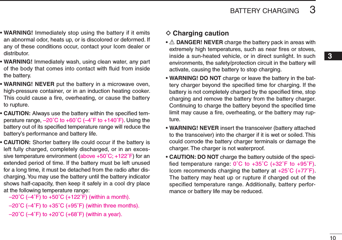
![3New2001New2001PANEL DESCRIPTION2New2001Front, top and side panels ■ID-31qewriotyu!0!2!3!4!1Function displayInternal microphoneSpeaker!5!6!7q ANTENNA CONNECTOR (p. 1) Connect the antenna here. •AnoptionalAD-92SMAadapter(p. 163) is available for connect-ing an antenna with a BNC connector.w TX/RX INDICATOR [TX/RX] (pp. 24, 26) Lights green while receiving a signal or when the squelch is open; lights red while transmitting.e PTT SWITCH [PTT] (p. 26) Hold down to transmit, release to receive.r SQUELCH KEY [SQL] (p. 17) Hold down to temporarily open the squelch and monitor ➥the operating frequency. While holding down this key, rotate ➥[DIAL] to adjust the squelch level.t MENU • LOCK KEY [MENU ] ➥ Push to enter or exit the Menu screen. (p. 115)➥ Hold down for 1 second to toggle the Lock func-tion ON or OFF. (p. 24)y FM/DV • SCAN KEY [FM/DV•SCAN] ➥ Push to select the operating mode. (p. 25) •SelectableoperatingmodesareFM,FMNandDV.➥ Hold down for 1 second to enter the scan type selection mode. (pp. 42, 44, 45) •Pushagaintostartthescan. •Push to stop the scan.](https://usermanual.wiki/ICOM-orporated/332200/User-Guide-1589996-Page-10.png)
![New200142PANEL DESCRIPTIONNew200112345678910111213141516171819u POWER KEY [ ] Hold down for 1 second to turn the transceiver pow-er ON or OFF. (p. 16)i microSD CARD SLOT [micro SD] (p. 26) Insert a microSD card of up to 32 GB SDHC.o CROSS KEYSCD (RX CALL RECORD)/LEFT KEY [CD] (p. 26) ➥ Hold down for 1 second to set the received call sign (station and repeaters) to current call signs. (p. 50)➥ While in the DR mode, or with the Menu screen or Quick Menu screen open, push to select an upper tier menu. (p. 115)CS (CALL SIGN)/RIGHT KEY [CS] (p. 26) ➥ Hold down for 1 second to enter the operating call sign select mode. (pp. 48, 59)➥ While in the DR mode, or with the Menu screen or Quick Menu screen open, push to select a lower tier menu. (p. 115)DR (D-STAR REPEATER)/DOWN KEY [DR] ➥ Hold down 1 second to enter the DR mode. (p. 25)➥ While in the DR mode, or with the Menu screen or Quick Menu screen open, push to move the value or option selector bar down. (p. 115)RXÚCS (D-STAR REPEATER)/DOWN KEY [DR] ➥ H old down for 1 second to set the received call signs (station and repeaters) to current call sign. (p. 50) •While holding down this key, rotate [DIAL] select a Received call sign record.➥ While in the DR mode, or with the Menu screen or Quick Menu screen open, push to move the value or option selector bar up. (p. 115)ENTER KEY While in the DR mode, or with the Menu screen or Quick Menu screen operation, push to open the selected set item or option. (p. 115)!0 QUICK MENU KEY [QUICK MENU] Push to enter or exit the Quick Menu screen. (p. 25) •TheQuickMenuisusedforchangingtheVFOsettingor a memory channel.!1 EXTERNAL DC IN JACK [DC IN] Connects to the supplied wall charger, BC-167SA/SC/ ➥SV,tochargetheattachedbatterypack.(p. 12) ➥Connect an external DC power supply through the op-tional CP-12L or CP-19R cigarette lighter cable or OPC-254L DC power cable for external DC operation. (p. 15)!2 DATA JACK [DATA] (pp. 74, 77, 158) Connects to a PC through the optional OPC-2218LU data communication cable, for low-speed data communication intheDVmodeorforcloning.Thejackandcablearealso](https://usermanual.wiki/ICOM-orporated/332200/User-Guide-1589996-Page-11.png)
![52PANEL DESCRIPTIONNew2001 New2001Front, top and side panels (Continued) ■ID-31qewriotyu!0!2!3!4!1Function displayInternal microphoneSpeaker!5!6!7!3 MEMORY/CALL • SELECT MEMORY WRITE KEY [M/CALL•S.MW] ➥ IntheVFOmode,push once to enter the Memory selection mode, push again to enter the Call memory selection mode. (pp. 18, 29, 30, 72) ➥ Hold down for 1 second to enter the Select Mem-ory Write mode. (p. 31)!4 VFO/MHz • CLEAR • OUTPUT POWER KEY [VFO/MHz•CLR•LOW] ➥ Push to selecttheVFOmode.(p. 25)➥WhileintheVFOmode,pushtoselect1MHztuning steps. (p. 22)➥ With the Menu screen or Quick Menu screen open, push to return to the operating mode be-fore entering the menu screen. (pp. 94, 115)➥ While in the Memory Name or Call Sign Program-ming mode, push to select an upper tier menu. (p. 115)➥ While scanning, push to cancel a scan. (pp. 104, 106, 107)➥ Hold down for 1 second to select the output pow-er. (pp. 42, 44, 45) •SelectthetransmitoutputpowerofHigh,Mid,LoworS-low. •While holding down this key, rotate [DIAL] to select the desired output power.](https://usermanual.wiki/ICOM-orporated/332200/User-Guide-1589996-Page-12.png)
![New200162PANEL DESCRIPTION12345678910111213141516171819!5 EXTERNAL SPEAKER/MICROPHONE JACK [SP/MIC] Connect a cloning cable, optional speaker microphone or headset, if desired. See page 163 for a list of available options. Be sure to turn power OFF before connecting or discon-necting optional equipment to or from the [SP/MIC] jack.!6 VOLUME CONTROL [VOL] Rotate to adjust audio volume level. (p. 16)!7 CONTROL DIAL [DIAL] Rotate to tune the operating frequency. ( ➥p. 22) While in the Memory mode, rotate to select a memory ➥channel. (pp. 18, 92) While scanning, rotate to change the scanning direc- ➥tion. (pp. 53, 104, 106, 107) Hold down ➥[SQL], and rotate to select the squelch level. (p. 17) While in the DR mode, or with the Menu screen or ➥Quick Menu screen open, rotate to select a desired op-tion or value. (p. 115)](https://usermanual.wiki/ICOM-orporated/332200/User-Guide-1589996-Page-13.png)
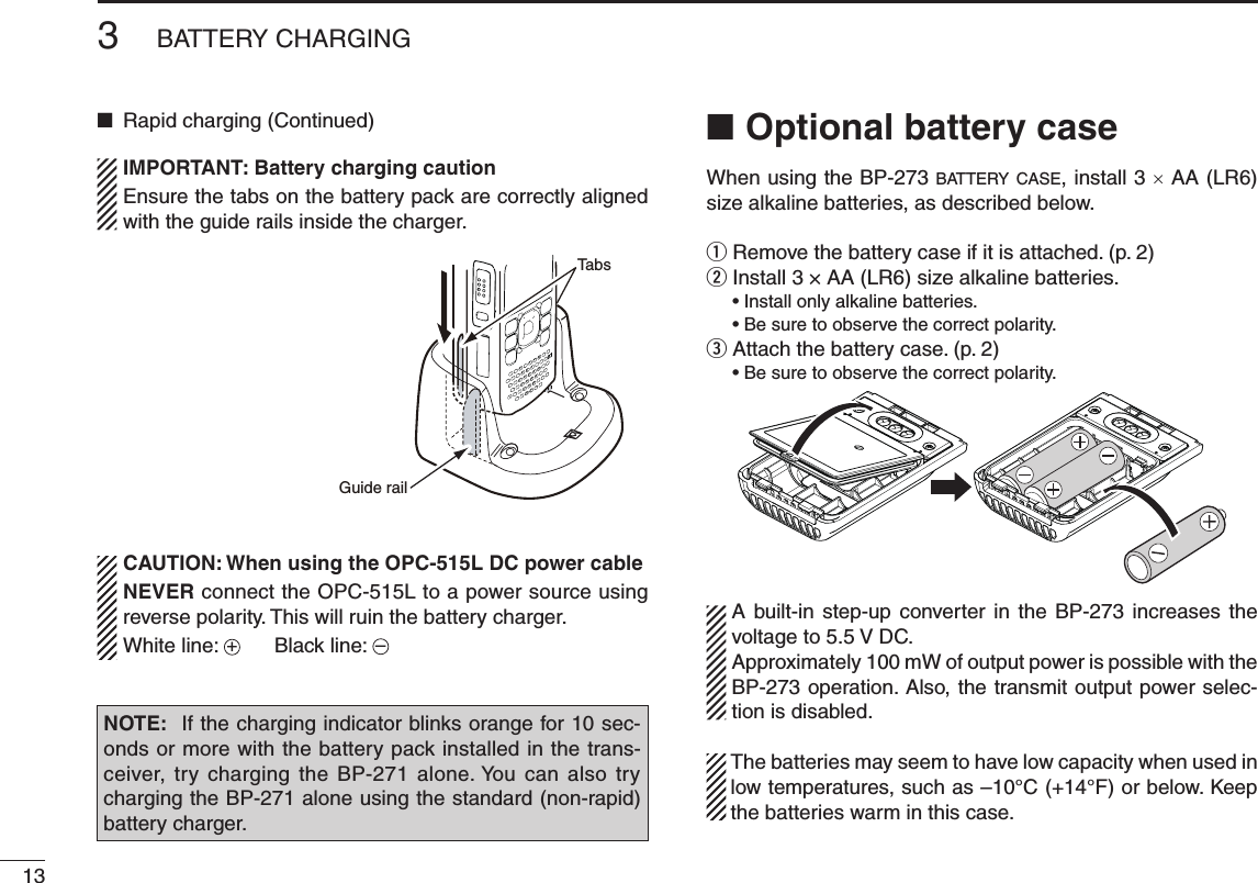
![New2001113BATTERY CHARGINGNew2001Regular charging ■Prior to using the transceiver for the first time, the battery pack must be fully charged for optimum life and operation.Battery icon DWhen the transceiver’s power is OFF, the charging icon se-quentially shows “ ,” “ ” and “ ” along with “Charging...” while charging. The icon disappears when the battery pack is completely charged.When the transceiver power is ON, the battery icon sequen-tially shows “ ,” “ ,” “ ” and “ ” while charging, and the icon disappears when the battery pack is completely charged.Charging note D•BesuretoturnthetransceiverpowerOFF.Otherwise the battery pack will not be charged completely or will take much longer to charge.•ExternalDCpowerispossiblewhenusinganoptionalCP-12L, CP-19R or OPC-254L. The attached battery pack is also charged simultaneously, except during transmit (see p. 16 for more details).•TheexternalDCpowersupplyvoltagemustbebetween10–16Vtochargethebatterypackandwhenoperatingusing an OPC-254L.• BC-167S• CP-12L (Optional)• OPC-254L (Optional)to AC outletto cigarette lightersocket (12 V DC)to 12 V DC(power supply)White: +Black: _Transceiverto [DC IN]Tu rn power OFF while charging the battery pack.The BC-167SA, BC-167SD and BC-167SV have different shapes.• Charging time period: Approx. 6 hoursBP-271 • CP-19R (Optional)](https://usermanual.wiki/ICOM-orporated/332200/User-Guide-1589996-Page-18.png)
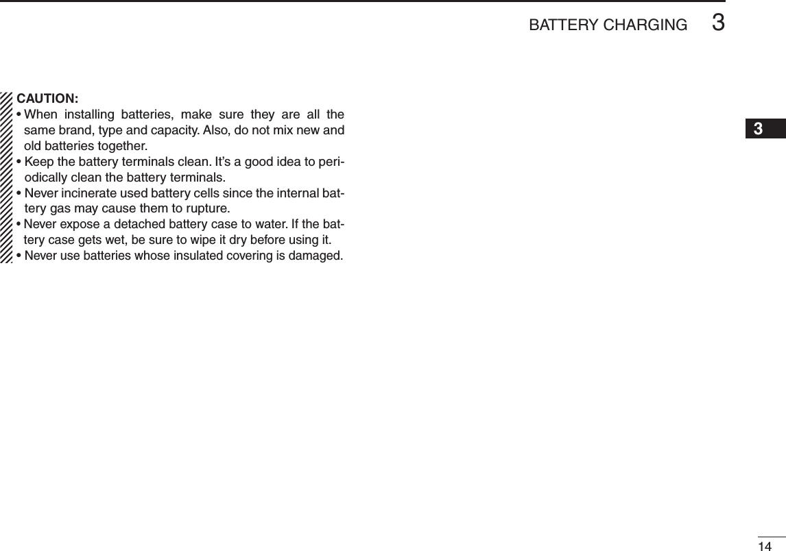
![123BATTERY CHARGINGNew20013Rapid charging ■The optional BC-202 rapidly charges of the BP-271 or BP-272 Li-ion battery packs.Charging note D•BesuretoturnOFFthetransceiverpower.When the transceiver power cannot be turned OFF, detach the battery pack from the transceiver then charge the battery pack by itself, or charge the battery using regular charging. Otherwise the battery pack will not be charged (the charg-ing indicator on the BC-202 blinks orange about 10 second after the battery pack is installed in BC-202).•TheBC-202desktopchargercanonlychargeBP-271orBP-272 Li-ion battery packs. Other types of rechargeable battery, Ni-Cd or Ni-MH cannot be charged.•Ifthechargingindicatorblinksorange,theremaybeaproblem with the battery pack or charger. If this occurs, try charging the battery pack alone, without the transceiver, or try using the standard (non-rapid) charger. Contact your dealer if you have problems charging a new battery pack.•NEVER place the transceiver with the battery pack to the desktop charger when the transceiver is connected to the DC power supply. This may cause the charger’s malfunc-tion and the charging indicator of the charger lights red. In that case, disconnect the AC adapter from the charger, and then reconnect the AC adapter to the charger.•TheoptionalCP-23LandOPC-515Lcanbeusedinsteadof the supplied AC adapter. Connect one of these to the [DC12-16V]jack.• Charging period: BP-271 approximately 2.0 hours BP-272 approximately 3.5 hoursTransceiver(with battery pack)Tu rn OFF the powerBattery packBC-202 (optional)Desktop chargerCharging indicator• Lights orange : While charging• Lights green : Charging is completed• Blinks orange : Charging error has occuredAC Adapter(A different type, or no AC adapter is supplied, depending on the version.)Screws*(Self tapping screw:3.5 × at least 30 mm)*Purchase separately.Using screws is recommended to secure the charger.The optional OPC-515L (for DC power source) or CP-23L (for 12 V cigarette lighter socket) can be used instead of the AC adapter.](https://usermanual.wiki/ICOM-orporated/332200/User-Guide-1589996-Page-19.png)
![163BATTERY CHARGING12345678910111213141516171819New2001External DC power operation ■An optional CP-12L or CP-19R cigarette lighter cable, for a 12Vcigarettelightersocket,oranOPC-254LexternalDCpower cable can be used for external power. Operating note D•The power supply voltage must be between 10.0–16.0 V DC. NEVER CONNECT OVER 16 V DC directly into the [DC IN] jack of the transceiver.•BE SURE to use a CP-12L, CP-19R or OPC-254L when connecting a regulated 12 VDCpowersupply. Use an external DC-DC converter to connect the transceiv-er through an optional CP-12L, CP-19R or OPC-254L to a 24 VDCpowersource.•Thevoltageoftheexternalpowersupplymustbebetween10–16V DC when usingeitherCP-12L,CP-19RorOPC-254L, otherwise, use the battery pack.•Disconnect the power cables from the transceiver whennot using it. Otherwise, the vehicle battery will become ex-hausted.•Thepowersavefunctionisautomaticallydeactivatedwhenusing an external DC power source.BP-217• CP-12L (Optional)• CP-19R (Optional)• OPC-254L (Optional)to a cigarette lightersocket (12 V DC)to a 12 V DC(power supply)White: +Black: _to [DC IN]TransceiverNOTE: Up to 5 W (approximately) of maximum output power is available when using external DC power. How-ever,whenthesupplyvoltageexceeds14V,thebuilt-inprotection circuit activates to reduce the transmit output power to approximately 2.5 W.](https://usermanual.wiki/ICOM-orporated/332200/User-Guide-1589996-Page-23.png)
![New2001New200117New2001BASIC OPERATION4New2001Power ON ■Hold down ➥ for 1 second to turn ON power. •Holddown for 1 second to turn OFF power. •Aftertheopeningmessageandpowersourcevoltagearedis-played, operating frequency appears.The opening message and power source voltage display op-tions are selectable in the DISPLAY menu.MENU ➪DISPLAY ➪Opening Message (p. 130)MENU ➪DISPLAY ➪Voltage Indication (p. 130)The beep level is adjusted in the SOUNDS menu.MENU ➪SOUNDS ➪Beep Level (p. 130)Setting audio volume ■Rotate[VOL] ➥to adjust the audio level. •Ifthesquelchisclosed,holddown[SQL]whilesettingtheaudiolevel. •Thedisplayshowsthevolumelevelwhilesetting.[VOL]VolumeleveldisplayMaximum CCW (no audio)Maximum CW (maximum audio)](https://usermanual.wiki/ICOM-orporated/332200/User-Guide-1589996-Page-24.png)
![New2001New2001New2001184BASIC OPERATION12345678910111213141516171819Setting squelch level ■The squelch circuit mutes the received audio signal, depend-ing on the signal strength. The transceiver has 9 squelch lev-els, a continuously open setting and an automatic squelch setting. While holding down [SQL], rotate [DIAL] to select the ➥squelch level. •Whileholdingdown[SQL],rotate[DIAL]oneclicktodisplaythesquelch level. •“LEVEL1” isloosesquelch(forweaksignals)and“LEVEL9”istight squelch (for strong signals). •“AUTO” indicates automatic level adjustment by a noise pulsecounting system. •“OPEN”indicatesacontinuouslyopensetting.(ThisoptionisnotselectableintheDVmode.)Monitor function ■This function is used to listen to weak signals without disturb-ing the squelch setting, or having to open the squelch manu-ally even when mute functions such as the tone squelch are in use.Hold down [SQL] to monitor the operating frequency. ➥ •The1stsegmentoftheS-meterblinks.MENU ➪FUNCTION ➪Monitor (p. 125) The [SQL] key can be set to ‘sticky’ operation in FUNC-TION menu. See page 125 for details.[SQL][DIAL]Automatic squelchMaximum level[SQL]The first segment blinks](https://usermanual.wiki/ICOM-orporated/332200/User-Guide-1589996-Page-25.png)
![194BASIC OPERATIONNew2001 New2001Mode selection ■VFO mode DVFOmodeisusedtosetthedesiredfrequency.Push ➥(V/MHz)toselectVFOmode.Memory mode DMemory mode is used for operation on memory channels which store programmed frequencies.Push q once or twice to select memory mode. •“ ” appears when memory mode is selected. •Push again to select Call channels. Memory mode or Call channels are alternately selected.• VFO mode display• Memory mode displayAppearsWhat is VFO?VFOisanabbreviationofVariableFrequencyOscillator.Fre-quencies for both transmitting and receiving are generated andcontrolledbytheVFO.Rotate w[DIAL] to select a desired memory channel. •Onlyprogrammedmemorychannelscanbeselected. •Seep.94formemoryprogrammingdetails.](https://usermanual.wiki/ICOM-orporated/332200/User-Guide-1589996-Page-26.png)
![New2001D Call channelsCall channels are used for quick recall of most-often used frequencies. Push q once or twice to select call channels. •Push again to select Memory mode. Memory mode or Call channels are alternately selected.204BASIC OPERATION12345678910111213141516171819DR (D-STAR Repeater) mode DDR (D-STAR Repeater) mode is used for D-STAR repeater operation. In this mode, you can select the pre-programmed repeaters and UR call sign easily by using [DIAL].D-STAR is an abbreviation for Digital Smart Technologies for Amateur Radio.Hold down q for 1 seconds to select DR mode.• Call channel display• DR mode displayRotate [DIAL] to select a desired Call channel. wRotate [DIAL] to select a desired access repeater. w](https://usermanual.wiki/ICOM-orporated/332200/User-Guide-1589996-Page-27.png)
![214BASIC OPERATIONNew2001 New2001Setting a tuning step ■The following tuning steps are selectable for the ID-31A or ID-31E. •5.0kHz •6.25kHz •10.0kHz •12.5kHz •15.0kHz •20.0kHz •25.0kHz •30.0kHz •50.0kHz •100.0kHz •125.0kHz •200.0kHzD Tuning step selectionq Push toselectVFOmode,if necessary.w Push to enter the Quick Menu screen.e Push the Up or Down key to se-lect the “TS” item.r Rotate [DIAL] to select the de-sired tuning step.t Push (or ) to return to VFOmode.Setting a frequency ■q Push toselectVFOmode,ifnecessary.w Rotate [DIAL] to select the desired frequency.•Thefrequencychangesaccordingtothepresettuningsteps. See the previous content to set the tuning step.•WhenVFOmodeisselected,push then rotate [DIAL] tochangethefrequencyin1MHzsteps.Push again to cancel it.5kHztuningstep[DIAL] changes the frequency according to the selected tuning step.After pushing [V/MHz] on VFOmode, [DIAL] changes the frequencyin1MHz steps.](https://usermanual.wiki/ICOM-orporated/332200/User-Guide-1589996-Page-28.png)
![New2001224BASIC OPERATION12345678910111213141516171819Operating mode selection ■Operating modes are determined by the modulation of the radio signals. The transceiver has total three operating modes,FM,FM-NandDVmodes.➥ Push (FM/DV)oneormoretimestoselectadesiredoperating mode.FM FM-N DVFM mode selectionFM-N mode selectionDVmodeselectionReceiving ■Make sure a charged battery pack (BP-271) or brand new alkaline batteries (BP-273) are installed (pp. 2, 14).Hold down q for 1 second to turn ON the power.Rotate[VOL]toadjustadesiredaudiolevel.(p.16) w •Thefrequencydisplayshowsthevolumelevelwhilesetting.Set the receiving frequency. (p. 23) er Set the squelch level. (p. 17) •Whileholdingdown[SQL],rotate[DIAL]oneclicktodisplaythesquelch level. •“LEVEL1” isloosesquelch(forweaksignals)and“LEVEL9”istight squelch (for strong signals). •“AUTO” indicates automatic level adjustment by a noise pulsecounting system. •Holddown[SQL]tomanuallyopenthesquelch.tWhenasignalisreceived: •Squelchopensandaudioisoutput. •Tx/Rxindicatorlightswhite. •TheS/RF-metershowstherelativesignalstrengthlevel.q r Set squelch levele Set frequencyw Adjust audio levelr Push for setting the squelch (Push to monitor)Tx/Rxindicator](https://usermanual.wiki/ICOM-orporated/332200/User-Guide-1589996-Page-29.png)
![234BASIC OPERATIONNew2001 New2001Transmitting ■CAUTION: Transmitting without an antenna will damage the transceiver.NOTE: To prevent interference, hold down [SQL] to listen on the channel before transmitting.q Set the operating frequency. (p. 23)•Transmission is available only onthe440MHzamateurband.•Selectoutputpowerifdesired.Seenext page for details.w Hold down [PTT] to transmit.•Tx/Rxindicatorlightsred.•S/RFmetershowstheoutputpowerlevel.e Speak into the microphone using your normal voice level.•DONOTholdthetransceivertooclosetoyourmouthorspeaktoo loudly. This may distort your speech.r Release [PTT] to return to receive.R WARNING! NEVER transmit for long periods of time. When the transceiver is used for prolonged transmissions at high power or middle power, the transceiver radiates heat to protect itself from overheating. The transceiver’s chassis will become hot and may cause a burn.•Topreventthetransceiver’soverheating,thedefaultsettingofthetime-out timer function is set to 5 minutes (p. 62). Be careful when the time-out timer function is turned OFF or set to a long time period, and transmission is made for long periods.DO NOT operate the transceiver in a situation that will obstruct heat dissipation, especially if the transceiver is operated with an external power supply. Heat dissipation may be affected, and it may cause a burn, warp the casing or damage the transceiver.NOTE:Whenthetransceiverbecomeshotfromcontinuoustransmission, etc., the transceiver’s heat protection function gradually reduces the output power to approximately 2.5 W, then it stops transmission after that. This is done to protect the transceiver itself until it has cooled down.CONNECT the rated voltage range when using external power supply.Tx/RxMicrophoneindicatorPTTSQL](https://usermanual.wiki/ICOM-orporated/332200/User-Guide-1589996-Page-30.png)
![New2001244BASIC OPERATION12345678910111213141516171819Transmit power selection ■The transceiver has four output power levels to suit your op-erating requirements. S-Low output power during short-range communications may reduce the possibility of interference to other stations and will conserve battery power.➥ Hold down (LOW) for 1 second to toggle the transmit output power between High (5W*), Mid (2.5 W*), Low (0.5 W*) and S-Low (0.1 W*). *approximately•Whileholdingdown (LOW), rotate [DIAL] to select the transmit power.Lock function ■To prevent accidental frequency changes and unnecessary function access, use the lock function. Hold down ➥ (LOCK) for 1 second to turn the lock func-tion ON or OFF. •Whilethelockfunctionisactivatedandthelockedkeyordialispushed or rotated, “LOCKED” will be displayed. • ,[VOL],[SQL],[PTT]and (LOCK) are operable while the lock function is activated. • Either or both the squelch control and volume control can also be locked in the Function menu.High power transmissionMid power transmissionLow power transmissionS-Low power transmissionONLY approximately 0.1 W transmission is available while attach-ing BP-273.MENU ➪SET ➪FUNC ➪LOCK (p. 127)ロック機能設定時ロック機能設定後操作したときの表示ロック機能解除時Appears](https://usermanual.wiki/ICOM-orporated/332200/User-Guide-1589996-Page-31.png)