ICOM orporated 332200 UHF Amateur Transceiver User Manual
ICOM Incorporated UHF Amateur Transceiver
User Manual

This device complies with Part 15 of the FCC Rules. Operation is
subject to the following two conditions: (1) this device may not cause
harmful interference, and (2) this device must accept any interference
received, including interference that may cause undesired operation.
WARNING: MODIFICATION OF THIS DEVICE TO RECEIVE CEL-
LULAR RADIOTELEPHONE SERVICE SIGNALS IS PROHIBITED
UNDER FCC RULES AND FEDERAL LAW.
INSTRUCTION MANUAL
New2001
ID-31A
UHF TRANSCEIVER
ID-31E
UHF TRANSCEIVER
The photo shows the
ID-31E version.

i
New2001 New2001
FOREWORD
Thank you for purchasing this fine Icom product. The ID-31A
or ID-31E u h f t r a n s c e i v e r is designed and build with Icom’s
superior technology and craftsmanship combining traditional
analog technologies with the new digital technology, Digital
Smart Technologies for Amateur Radio (D-STAR), for a bal-
anced package. With proper care, this product should provide
you with years of trouble-free operation.
We thank you for making your ID-31A or ID-31E your radio of
choice, and hope you agree with Icom’s philosophy of “tech-
nology first.” Many hours or research and development went
into the design of your ID-31A or ID-31E.
FEATURES
❍ DV mode (Digital voice + Low-speed data
communication) operation-ready
– Text message and call sign exchange
– Transmit position data
❍ DR (D-STAR Repeater) mode and repeater
list allow you to easily operate using a D-
STAR repeater
❍ GPS receiver installed
❍ GPS Logger function allows you to check
your route as you move
❍ Waterproof construction (IPX7*)
* Only when the supplied battery pack, antenna and
jack cover are attached.
❍ microSD card slot
Spurious signals may be received in the DV mode near the
following frequencies. These are made in the internal circuit
and does not indicate a transceiver malfunction.
430.080 MHz, 442.370 MHz
For Canada:
This device complies with RSS-310 of Industry Canada.
Operation is subject to the condition that this device does
not cause harmful interference.
Cet appareil est conforme au CNR-310 d’Industrie Canada.
Son exploitation est autorisée sous réserve que l’appareil
ne cause pas de brouillage préjudiciable.

New2001
ii
FCC INFORMATION
• FOR CLASS B UNINTENTIONAL RADIATORS:
This equipment has been tested and found to comply with the
limits for a Class B digital device, pursuant to part 15 of the
FCC Rules. These limits are designed to provide reasonable
protection against harmful interference in a residential instal-
lation. This equipment generates, uses and can radiate radio
frequency energy and, if not installed and used in accordance
with the instructions, may cause harmful interference to radio
communications. However, there is no guarantee that inter-
ference will not occur in a particular installation. If this equip-
ment does cause harmful interference to radio or television
reception, which can be determined by turning the equipment
off and on, the user is encouraged to try to correct the inter-
ference by one or more of the following measures:
•Reorientorrelocatethereceivingantenna.
•Increasetheseparationbetweentheequipmentandre-
ceiver.
•Connecttheequipmentintoanoutletonacircuitdifferent
from that to which the receiver is connected.
•Consultthedealeroranexperiencedradio/TVtechnician
for help.
EXPLICIT DEFINITIONS
WORD DEFINITION
R DANGER! Personal death, serious injury or an ex-
plosion may occur.
R WARNING! Personal injury, fire hazard or electric
shock may occur.
CAUTION Equipment damage may occur.
NOTE Recommended for optimum use. No risk
of personal injury, fire or electric shock.
IMPORTANT
READ ALL INSTRUCTIONS carefully and completely
before using the transceiver.
SAVE THIS INSTRUCTION MANUAL— This
instruction manual contains important operating instructions
for the ID-31A/ID-31E.
CAUTION: Changes or modifications to this device, not
expressly approved by Icom Inc., could void your authority
to operate this device under FCC regulations.

iii
New2001 New2001
R DANGER! NEVER short the terminals of the bat-
tery pack.
R DANGER! NEVER Use and charge only specified
Icom battery packs with Icom radios or Icom chargers. Only
Icom battery packs are tested and approved for use with Icom
radios or charged with Icom chargers. Using third-party or
counterfeit battery packs or chargers may cause smoke, fire,
or cause the battery to burst.
R WARNING RF EXPOSURE! This device emits
Radio Frequency (RF) energy. Caution should be observed
when operating this device. If you have any questions regard-
ing RF exposure and safety standards please refer to the
Federal Communications Commission Office of Engineering
and Technology’s report on Evaluating Compliance with FCC
Guidelines for Human Radio Frequency Electromagnetic
Fields (OET Bulletin 65)
R WARNING! NEVER hold the transceiver so that
the antenna is very close to, or touching exposed parts of
the body, especially the face or eyes, while transmitting. The
transceiver will perform best if the microphone is 5 to 10 cm
(2 to 4 inches) away from the lips and the transceiver is verti-
cal.
R WARNING! NEVER operate the transceiver with
an earphone, headphones or other audio accessories at high
volume levels. Hearing experts advise against continuous
high volume operation. If you experience a ringing in your
ears, reduce the volume level or discontinue use.
R WARNING! NEVER operate the transceiver while
driving a vehicle. Safe driving requires your full attention—
anything less may result in an accident.
R WARNING! NEVER connect the transceiver to a
power source of more than 16 V DC or use reverse polarity.
This could cause a fire or damage the transceiver.
R WARNING! NEVER operate or touch the trans-
ceiver with wet hands. This may result in an electric shock or
may damage the transceiver.
CAUTION: MAKE SURE the flexible antenna and
battery pack are securely attached to the transceiver, and
that the antenna and battery pack are dry before attachment.
Exposing the inside of the transceiver to water will result in
serious damage to the transceiver.
After exposure to water, clean the battery contacts thoroughly
with fresh water and dry them completely to remove any wa-
ter or salt residue.
PRECAUTIONS

New2001
iv
1
2
3
4
5
6
7
8
9
10
11
12
13
14
15
16
17
18
19
CAUTION: DO NOT use harsh solvents such as ben-
zine or alcohol to clean the transceiver, because they can
damage the transceiver’s surfaces.
DO NOT operate the transceiver near unshielded electri-
cal blasting caps or in an explosive atmosphere.
DO NOT push the PTT unless you actually intend to trans-
mit.
BE CAREFUL! The transceiver will become hot when op-
erating it continuously for long periods of time.
DO NOT use or place the transceiver in direct sunlight
or in areas with temperatures below –20°C (–4˚F) or above
+60°C (+140˚F).
Place the unit in a secure place to avoid inadvertent use by
children.
BE CAREFUL! The transceiver meets IPX7* require-
ments for waterproof protection. However, once the trans-
ceiver has been dropped, waterproof protection cannot be
guaranteed because of possible damage to the transceiver's
case or waterproof seal.
* Only when the BP-271 or BP-272 (option), flexible antenna,
[MIC/SP]capand[DATA/DCIN]capareattached.
The BP-273 meets IPX4 requirements for splash resistance.
When it is connected, the transceiver corresponds to IPX4.
Even when the transceiver power is OFF, a slight current still
flows in the circuits. Remove the battery pack or batteries from
the transceiver when not using it for a long time. Otherwise,
the installed battery pack or batteries will become exhausted,
and will need to be recharged or replaced.
PRECAUTIONS

v
New2001 New2001
PRECAUTIONS
D Important notes when using the GPS re-
ceiver
•TheGPSsignalcannotpassthroughmetalobjects.When
using the ID-31A or ID-31E inside a vehicle, you may not
receive GPS signals. We recommend you use it near a win-
dow. Please avoid the areas shown in the following:
1. DO NOT use where it will block the driver’s view.
2. DO NOT use where the air bags could deploy.
3. DO NOT use where it becomes a driving obstacle.
•TheGlobalPositioningSystem(GPS)isbuiltandoperated
by the U.S. Department of Defence. The Department is re-
sponsible for accuracy and maintenance of the system. Any
changes by the Department may affect the accuracy and
function of the GPS system.
•WhentheGPSreceiverisactivated,pleasedonotcoverthe
ID-31A or ID-31E with any object.
•TheGPSreceivermaynotworkifusedinthefollowingloca-
tions:
1. Tunnels or high-rise buildings
2. Underground parking lot
3. Under a bridge or viaduct
4. In remote forested areas
5. Under bad weather conditions (rainy or cloudy day)
•TheGPSreceivermaynotworkifthetransceiveroperates
near the 440.205 MHz. These are made in the internal cir-
cuit and does not indicate a transceiver malfunction.
New2001
vi
1
2
3
4
5
6
7
8
9
10
11
12
13
14
15
16
17
18
19
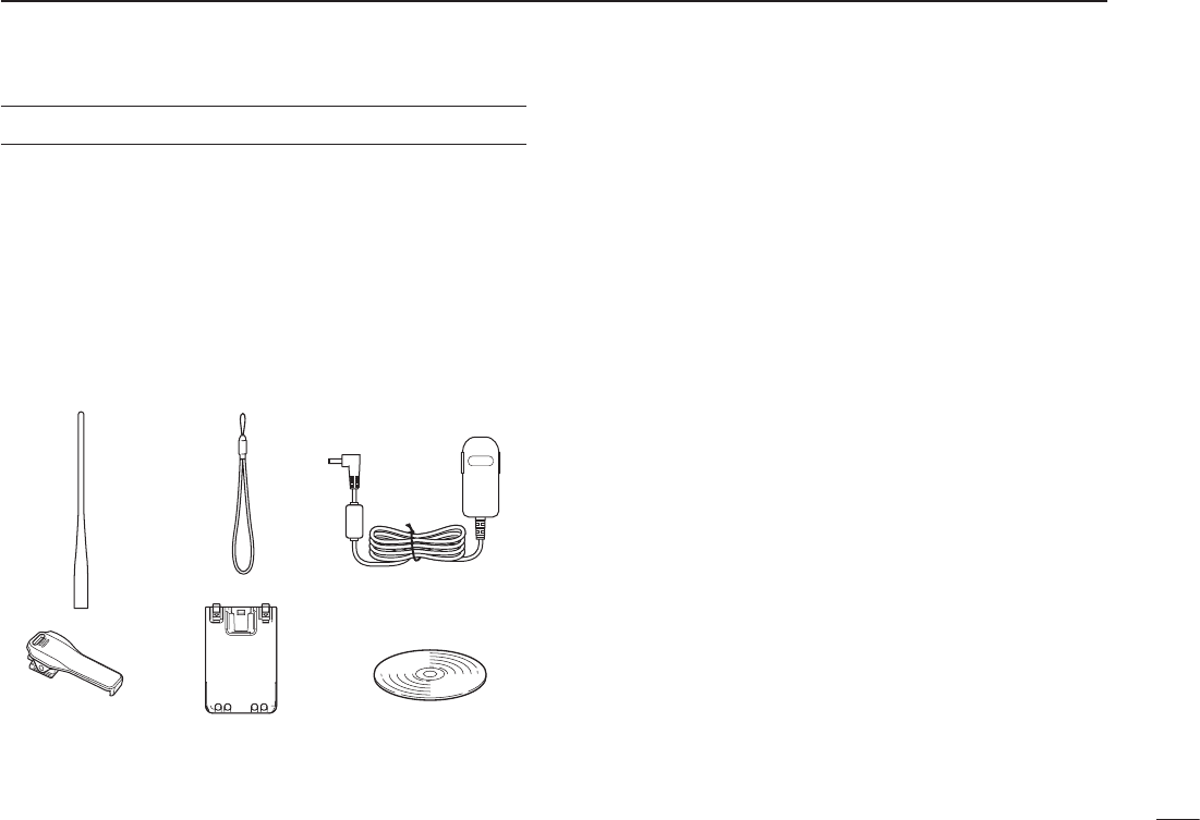
SUPPLIED ACCESSORIES
The following accessories are supplied with the transceiver.
q Antenna .......................................................................... 1
w Hand strap ..................................................................... 1
eBatterycharger(BC-167SA/SD/SV)* ............................. 1
r Belt clip .......................................................................... 1
t Battery pack (BP-271) .................................................... 1
* Not supplied, or the shape is different, depending on the transceiver
version.
Icom, Icom Inc. and the Icom logo are registered trademarks of Icom
Incorporated (Japan) in Japan, the United States, the United King-
dom,Germany,France,Spain,Russiaand/orothercountries.
APRS® is a registered trademark of Mr. Bob Bruninga in the U.S.A.
and other countries.
Microsoft, Windows and Windows Vista are registered trademarks of
MicrosoftCorporationintheUnitedStatesand/orothercountries.
1
New2001New2001
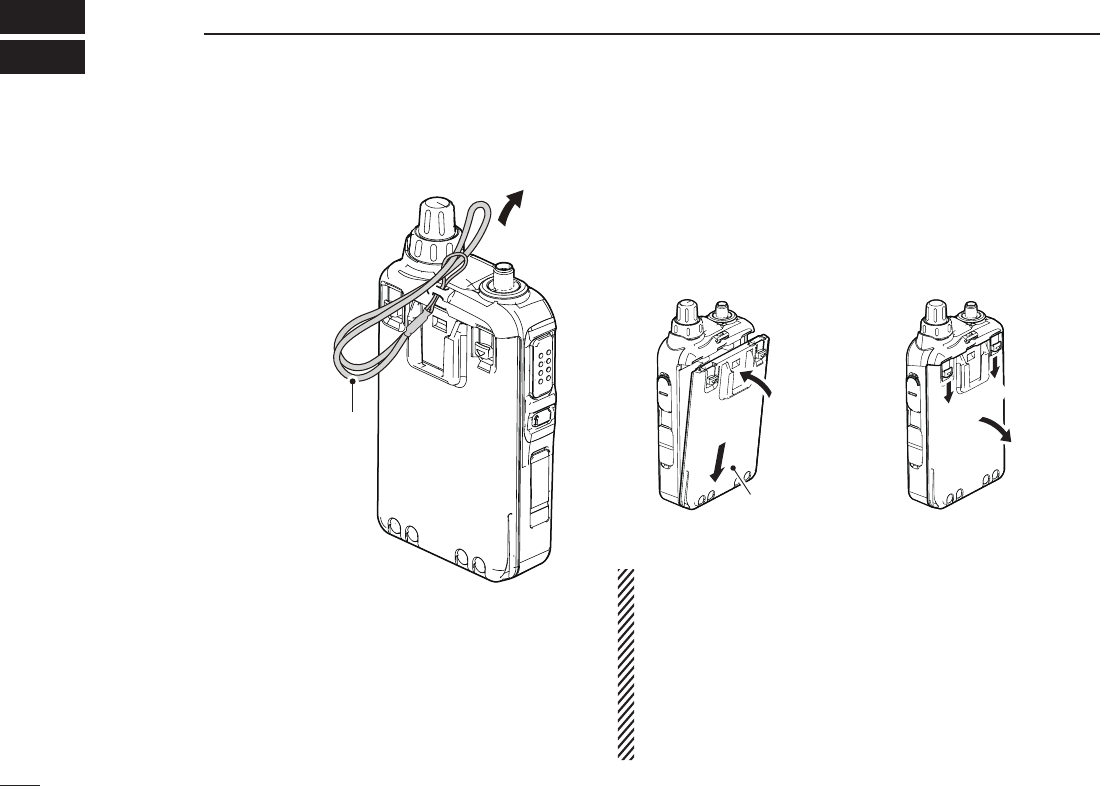
ACCESSORY ATTACHMENT
1
New2001
Hand strap ■
To facilitate carrying the trans-
ceiver, slide the hand strap
through the loop on the top of
the rear panel, as illustrated to
the right.
Battery pack ■
To attach or detach the battery pack:
To attach or detach the battery pack or battery case, follow
the illustrations below.
q
q
q
w
w
Even when the transceiver power is OFF, a small current
still flows in the radio. Remove the battery pack or case
from the transceiver when not using it for a long time. Oth-
erwise, the battery pack or installed batteries will become
exhausted.
The battery protection function automatically sets trans-
ceiver to Low power (0.5 W) when the temperature is 0°C
(+32°F) or below. In this case, transmit power selections
(High and Mid) are also disabled.
Hand strap
To attach
Battery pack
or battery case
To Detach
New2001
2
1
ACCESSORY ATTACHMENT
New2001
1
2
3
4
5
6
7
8
9
10
11
12
13
14
15
16
17
18
19
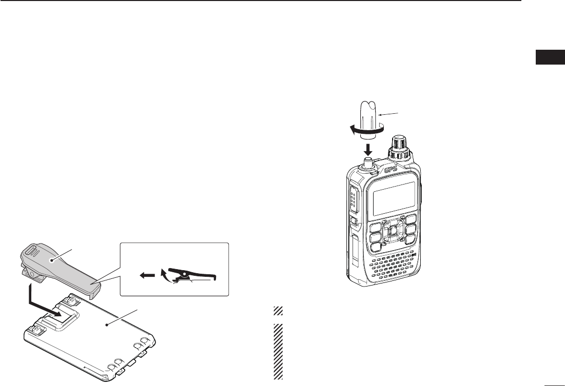
Belt clip ■
To attach the belt clip:
Slide the belt clip in the direction of the arrow until the belt clip
locks in place, and makes a ‘click’ sound.
Remove the battery pack from the transceiver, if it is at- q
tached. (p. 2)
wSlide the belt clip in the direction of the arrow until the belt
clip locks in place, and makes a ‘click’ sound..
To detach the belt clip:
Remove the battery pack from the transceiver, if it is at- q
tached. (p. 2)
Lift the tab up ( wq), and slide the belt clip in the direction
of the arrow (w).
q
w
Antenna ■
Insert the antenna connector into the antenna base and tight-
en the antenna base.
NEVER carry the transceiver by holding only the antenna.
✔ For your information
Third-party antennas may increase transceiver perfor-
mance. An optional AD-92SMA a n t e n n a c o n n e c t o r
a d a p t e r is available to connect an antenna that has a BNC
connector.
Antenna
Belt crip
To attach
To detach
Battery pack (BP-271)
3
New2001New2001
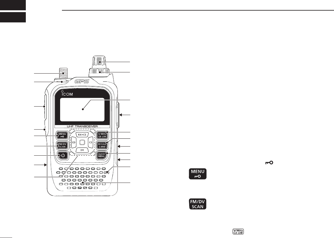
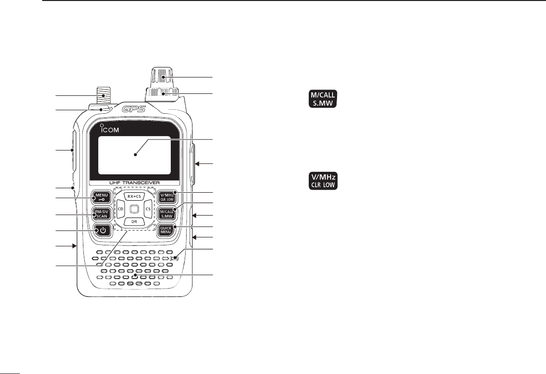
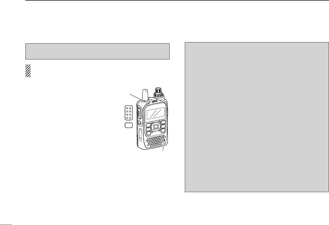
PANEL DESCRIPTION
2
New2001
Front, top and side panels ■
ID-31
q
e
w
r
i
o
t
y
u!0
!2
!3
!4
!1
Function display
Internal
microphone
Speaker
!5
!6
!7
q ANTENNA CONNECTOR (p. 1)
Connect the antenna here.
•AnoptionalAD-92SMAadapter(p. 163) is available for connect-
ing an antenna with a BNC connector.
w TX/RX INDICATOR [TX/RX] (pp. 24, 26)
Lights green while receiving a signal or when the squelch
is open; lights red while transmitting.
e PTT SWITCH [PTT] (p. 26)
Hold down to transmit, release to receive.
r SQUELCH KEY [SQL] (p. 17)
Hold down to temporarily open the squelch and monitor ➥
the operating frequency.
While holding down this key, rotate ➥[DIAL] to adjust the
squelch level.
t MENU • LOCK KEY [MENU ]
➥ Push to enter or exit the Menu screen. (p. 115)
➥ Hold down for 1 second to toggle the Lock func-
tion ON or OFF. (p. 24)
y FM/DV • SCAN KEY [FM/DV•SCAN]
➥ Push to select the operating mode. (p. 25)
•SelectableoperatingmodesareFM,FMNandDV.
➥ Hold down for 1 second to enter the scan type
selection mode. (pp. 42, 44, 45)
•Pushagaintostartthescan.
•Push to stop the scan.
New2001
4
2
PANEL DESCRIPTION
New2001
1
2
3
4
5
6
7
8
9
10
11
12
13
14
15
16
17
18
19
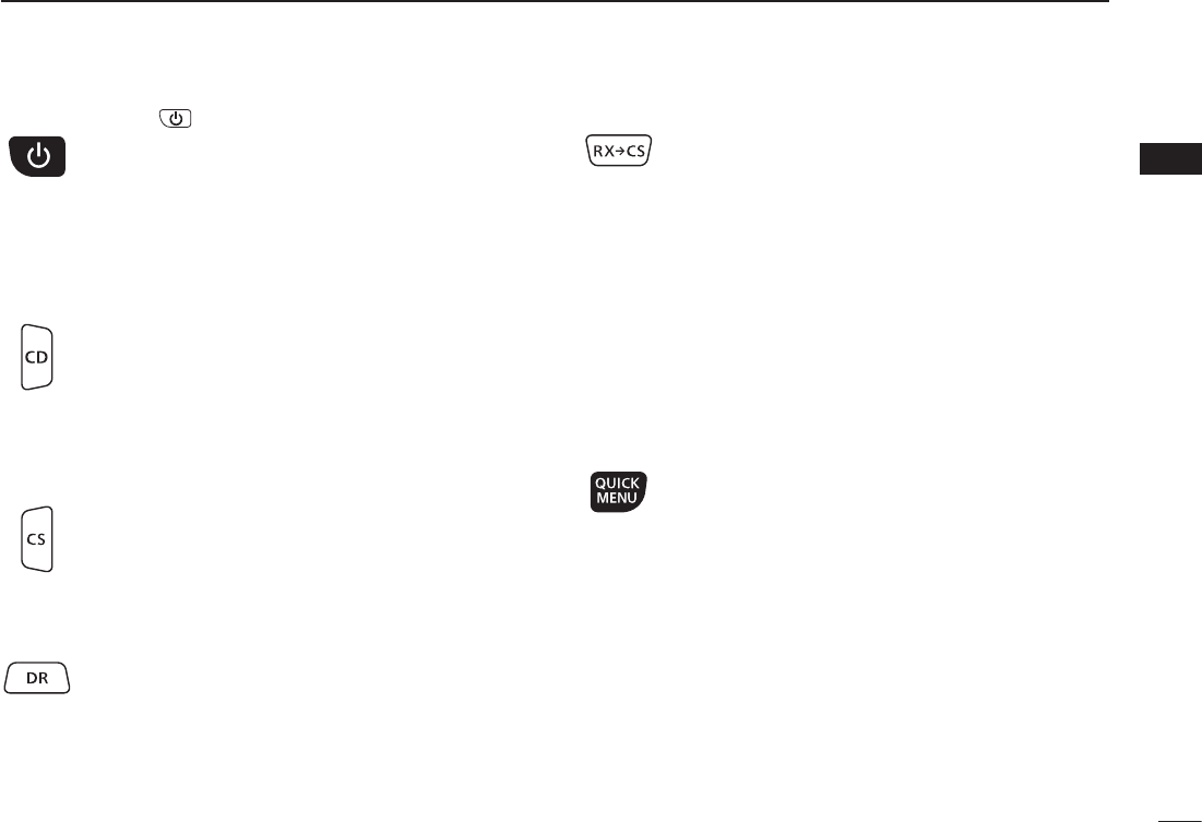
u POWER KEY [ ]
Hold down for 1 second to turn the transceiver pow-
er ON or OFF. (p. 16)
i microSD CARD SLOT [micro SD] (p. 26)
Insert a microSD card of up to 32 GB SDHC.
o CROSS KEYS
CD (RX CALL RECORD)/LEFT KEY [CD] (p. 26)
➥ Hold down for 1 second to set the received call
sign (station and repeaters) to current call signs.
(p. 50)
➥ While in the DR mode, or with the Menu screen or
Quick Menu screen open, push to select an upper
tier menu. (p. 115)
CS (CALL SIGN)/RIGHT KEY [CS] (p. 26)
➥ Hold down for 1 second to enter the operating call
sign select mode. (pp. 48, 59)
➥ While in the DR mode, or with the Menu screen or
Quick Menu screen open, push to select a lower
tier menu. (p. 115)
DR (D-STAR REPEATER)/DOWN KEY [DR]
➥ Hold down 1 second to enter the DR mode. (p.
25)
➥ While in the DR mode, or with the Menu screen or
Quick Menu screen open, push to move the value
or option selector bar down. (p. 115)
RXÚCS (D-STAR REPEATER)/DOWN KEY [DR]
➥ H old down for 1 second to set the received call
signs (station and repeaters) to current call sign.
(p. 50)
•While holding down this key, rotate [DIAL] select a
Received call sign record.
➥ While in the DR mode, or with the Menu screen or
Quick Menu screen open, push to move the value
or option selector bar up. (p. 115)
ENTER KEY
While in the DR mode, or with the Menu screen or Quick
Menu screen operation, push to open the selected set item
or option. (p. 115)
!0 QUICK MENU KEY [QUICK MENU]
Push to enter or exit the Quick Menu screen. (p. 25)
•TheQuickMenuisusedforchangingtheVFOsetting
or a memory channel.
!1 EXTERNAL DC IN JACK [DC IN]
Connects to the supplied wall charger, BC-167SA/SC/ ➥
SV,tochargetheattachedbatterypack.(p. 12)
➥
Connect an external DC power supply through the op-
tional CP-12L or CP-19R cigarette lighter cable or OPC-
254L DC power cable for external DC operation. (p. 15)
!2 DATA JACK [DATA] (pp. 74, 77, 158)
Connects to a PC through the optional OPC-2218LU data
communication cable, for low-speed data communication
intheDVmodeorforcloning.Thejackandcablearealso
5
2PANEL DESCRIPTION
New2001 New2001
Front, top and side panels (Continued) ■
ID-31
q
e
w
r
i
o
t
y
u!0
!2
!3
!4
!1
Function display
Internal
microphone
Speaker
!5
!6
!7
!3 MEMORY/CALL • SELECT MEMORY WRITE KEY
[M/CALL•S.MW]
➥ IntheVFOmode,push once to enter the Memory
selection mode, push again to enter the Call
memory selection mode. (pp. 18, 29, 30, 72)
➥ Hold down for 1 second to enter the Select Mem-
ory Write mode. (p. 31)
!4 VFO/MHz • CLEAR • OUTPUT POWER KEY
[VFO/MHz•CLR•LOW]
➥ Push to selecttheVFOmode.(p. 25)
➥WhileintheVFOmode,pushtoselect1MHz
tuning steps. (p. 22)
➥ With the Menu screen or Quick Menu screen
open, push to return to the operating mode be-
fore entering the menu screen. (pp. 94, 115)
➥ While in the Memory Name or Call Sign Program-
ming mode, push to select an upper tier menu. (p.
115)
➥ While scanning, push to cancel a scan. (pp. 104,
106, 107)
➥ Hold down for 1 second to select the output pow-
er. (pp. 42, 44, 45)
•SelectthetransmitoutputpowerofHigh,Mid,Lowor
S-low.
•While holding down this key, rotate [DIAL] to select
the desired output power.

New2001
6
2
PANEL DESCRIPTION
1
2
3
4
5
6
7
8
9
10
11
12
13
14
15
16
17
18
19
!5 EXTERNAL SPEAKER/MICROPHONE JACK [SP/MIC]
Connect a cloning cable, optional speaker microphone or
headset, if desired.
See page 163 for a list of available options.
Be sure to turn power OFF before connecting or discon-
necting optional equipment to or from the [SP/MIC]
jack.
!6 VOLUME CONTROL [VOL]
Rotate to adjust audio volume level. (p. 16)
!7 CONTROL DIAL [DIAL]
Rotate to tune the operating frequency. ( ➥p. 22)
While in the Memory mode, rotate to select a memory ➥
channel. (pp. 18, 92)
While scanning, rotate to change the scanning direc- ➥
tion. (pp. 53, 104, 106, 107)
Hold down ➥[SQL], and rotate to select the squelch
level. (p. 17)
While in the DR mode, or with the Menu screen or ➥
Quick Menu screen open, rotate to select a desired op-
tion or value. (p. 115)
New2001
7
2PANEL DESCRIPTION
New2001
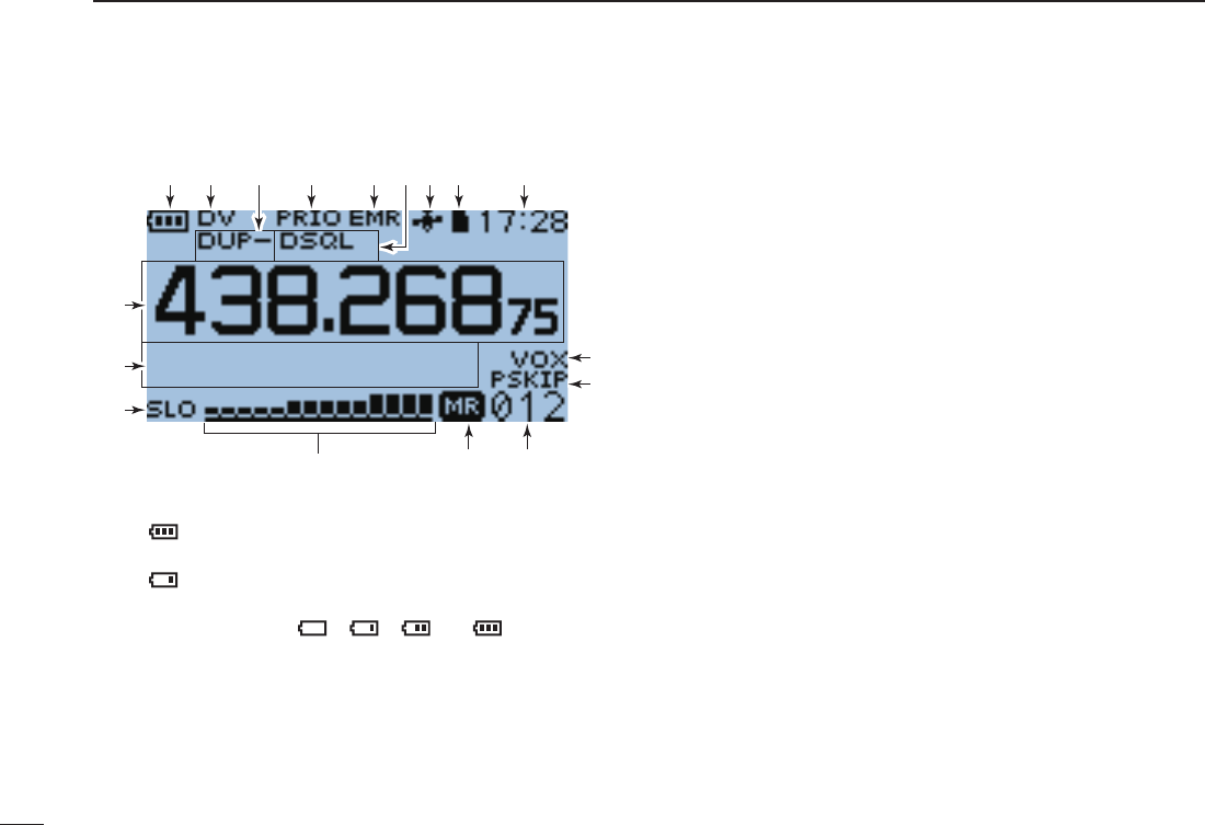
■ Function display
qw r t yu i
!1
!0
!4 !3 !2
!7
!6
!5
o
e
q BATTERY ICON (pp. 12, 14)
➥ “ ” (battery icon) appears when the battery pack is
attached.
➥ “ ” appears when the battery pack must be charged.
➥ While charging the attached battery pack, the icon se-
quentially shows “ ,” “ ,” “ ” or “ .”
w OPERATING MODE ICONS (p. 25)
Shows the selected operating mode.
•DV,FMandFMNareselectable.
•“DV-G”or“DV-A” appears when GPS or GPS-A transmission is
selectedintheDVmode.(p. 138)
e DUPLEX ICON (p. 31)
“ DUP” appears when plus duplex is selected, and “DUP–”
appears when minus duplex is selected.
r PRIORITY WATCH ICON (pp. 112–114)
Appears when Priority Watch is in use.
t EMR ICON (pp. 112–114)
Appears when Enhanced Monitor Request (EMR) mode
is selected.
y TONE ICONS
• While operating in FM/FM N mode;
➥ “ TONE” appears while the Repeater Tone Encoder is
ON. (p. 29)
➥ “ TSQL” appears while the Tone squelch function is ON.
(p. 150)
➥ “ TSQL-R” appears while the Reverse Tone squelch
function is ON. (p. 150)
➥ “ DTCS” appears while the DTCS squelch function is
ON. (p. 150)
➥ “ DTCS-R” appears while the reverse DTCS squelch
function is ON. (p. 150)
➥ “ S” appears with the “TSQL” or “DTCS” icon while
the Pocket Beep function (with CTCSS or DTCS) is
ON. (p. 151)

8
2
PANEL DESCRIPTION
New2001
2
• While operating in DV mode;
➥ “ DSQL” appears while the Digital Call Sign squelch
function is ON. (p. 151)
➥ “ CSQL” appears while the Digital Code squelch function
is ON. (p. 151)
➥ “ S” appears with the “DSQL” or “CSQL” icon while the
Pocket Beep function (with Digital Call Sign or Digital
Code squelch) is ON. (p. 151)
u GPS ICON
Appears while GPS function is in use.
•GPSiconscanbeturnedOFFinthe GPS Set menu. (p. 137)
➥ Stays ON when the internal GPS receiver is activated
and a valid position data is received.
➥ Blinks when an invalid position data is being received.
i microSD ICON (pp. 112–114)
Appears while a microSD card is inserted.
o CLOCK DISPLAY (pp. 112–114)
Displays the current time.
!0 VOX ICON (pp. 112–114)
AppearswhentheVOXfunctionisON.
!1 SKIP ICON
➥ “ SKIP” appears when the selected memory channel is
set as a skip channel. (pp. 108, 109)
➥ “ PSKIP” appears when the displayed frequency is set as
a skip frequency in the Memory mode. (pp. 108, 109)
➥ “ PSKIP” appears while the Frequency Skip Scan func-
tionisONintheVFOmode.(p. 102)
!2 MEMORY CHANNEL NUMBER
➥ Displays the selected memory channel number.
(pp. 18, 92)
➥ “C0” or “C1” appears when the Call channel is selected.
(pp. 19, 93)
!3 MEMORY ICON (pp. 18, 92)
Appears when the Memory mode is selected.
!4 S/RF METER
➥ Shows the relative signal strength of the receive signal.
(p. 24)
➥ Shows the output power level of the transmit signal.
(pp. 26, 27)
!5 POWER ICONS (p. 27)
➥ “ SLO” appears when S-low power is selected.
➥ “ LOW” appears when low power is selected.
➥ “ MID” appears when mid power is selected.
➥ No icon appears when high power is selected.
!6 MEMORY NAME DISPLAY (p. 24)
While in the Memory mode, the programmed memory or
memory bank name is displayed.
!7 FREQUENCY READOUT
Displays a variety of information, such as the operating
frequency, menu contents and so on.
•Thedecimalpointblinksduringascan.

New2001
9
New2001
BATTERY CHARGING
3
Caution ■
•R DANGER! NEVER short the terminals (or charging termi-
nals) of the battery pack. Also, current may flow into nearby
metal objects such as a key, so be careful when placing
battery packs (or the transceiver) in bags, etc.
Simply carrying with or placing near metal objects such as
a necklace, etc. may cause shorting. This may damage not
only the battery pack, but also the transceiver.
•R DANGER! Use and charge only specified Icom battery
packs with Icom radios or Icom charger. Only Icom battery
packs are tested and approved for use with Icom radios or
charged with Icom chargers. Using third-party or counterfeit
battery packs may cause smoke, fire, or cause the battery
to burst.
Battery caution D
•R DANGER! DO NOT hammer or otherwise impact the bat-
tery. Do not use the battery if it has been severely impacted
or dropped, or if the battery has been subjected to heavy
pressure. Battery damage may not be visible on the outside
of the case. Even if the surface of the battery does not show
cracks or any other damage, the cells inside the battery may
rupture or catch fire.
•R DANGER! NEVER use or leave battery pack in areas
with temperatures above +60˚C (+140˚F). High tempera-
ture buildup in the battery, such as could occur near fires
or stoves, inside a sun heated car, or in direct sunlight may
cause the battery to rupture or catch fire. Excessive tem-
peratures may also degrade battery performance or shorten
battery life.
•R DANGER! DO NOT expose the battery to rain, snow,
seawater, or any other liquids. Do not charge or use a wet
battery. If the battery gets wet, be sure to wipe it dry before
using.
•R DANGER! NEVER incinerate a used battery pack since
internal battery gas may cause it to rupture, or may cause
an explosion.
•R
DANGER! NEVER solder the battery terminals, or
NEVER modify the battery pack. This may cause heat gen-
eration, and the battery may burst, emit smoke or catch fire.
•R DANGER! Use the battery only with the transceiver for
which it is specified. Never use a battery with any other
equipment, or for any purpose that is not specified in this
instruction manual.
•R DANGER! If fluid from inside the battery gets in your
eyes, blindness can result. Rinse your eyes with clean water,
without rubbing them, and see a doctor immediately.
Misuse of Lithium-Ion batteries may result in the following
hazards:smoke,re,orthebatterymayrupture.Misuse
can also cause damage to the battery or degradation of
battery performance.
New2001

New2001
10
3
BATTERY CHARGING
New2001
1
2
3
4
5
6
7
8
9
10
11
12
13
14
15
16
17
18
19
•WARNING! Immediately stop using the battery if it emits
an abnormal odor, heats up, or is discolored or deformed. If
any of these conditions occur, contact your Icom dealer or
distributor.
•WARNING! Immediately wash, using clean water, any part
of the body that comes into contact with fluid from inside
the battery.
•WARNING! NEVER put the battery in a microwave oven,
high-pressure container, or in an induction heating cooker.
This could cause a fire, overheating, or cause the battery
to rupture.
•CAUTION: Always use the battery within the specified tem-
perature range, –20˚C to +60˚C (–4˚F to +140˚F). Using the
battery out of its specified temperature range will reduce the
battery’s performance and battery life.
•CAUTION: Shorter battery life could occur if the battery is
left fully charged, completely discharged, or in an exces-
sive temperature environment (above +50˚C; +122˚F) for an
extended period of time. If the battery must be left unused
for a long time, it must be detached from the radio after dis-
charging. You may use the battery until the battery indicator
shows half-capacity, then keep it safely in a cool dry place
atthefollowingtemperaturerange:
–20˚C (–4˚F) to +50˚C (+122˚F) (within a month).
–20˚C (–4˚F) to +35˚C (+95˚F) (within three months).
–20˚C (–4˚F) to +20˚C (+68˚F) (within a year).
Charging caution D
•R DANGER! NEVER charge the battery pack in areas with
extremely high temperatures, such as near fires or stoves,
inside a sun-heated vehicle, or in direct sunlight. In such
environments, the safety/protection circuit in the battery will
activate, causing the battery to stop charging.
•WARNING! DO NOT charge or leave the battery in the bat-
tery charger beyond the specified time for charging. If the
battery is not completely charged by the specified time, stop
charging and remove the battery from the battery charger.
Continuing to charge the battery beyond the specified time
limit may cause a fire, overheating, or the battery may rup-
ture.
•WARNING! NEVER insert the transceiver (battery attached
to the transceiver) into the charger if it is wet or soiled. This
could corrode the battery charger terminals or damage the
charger. The charger is not waterproof.
•CAUTION: DO NOT charge the battery outside of the speci-
edtemperaturerange:0˚C to +35˚C (+32˚F to +95˚F).
Icom recommends charging the battery at +25˚C (+77˚F).
The battery may heat up or rupture if charged out of the
specified temperature range. Additionally, battery perfor-
mance or battery life may be reduced.
New2001
11
3BATTERY CHARGING
New2001
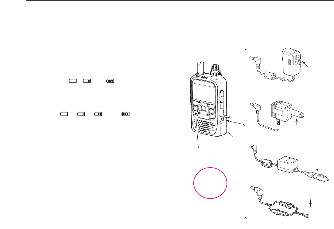
Regular charging ■
Prior to using the transceiver for the first time, the battery
pack must be fully charged for optimum life and operation.
Battery icon D
When the transceiver’s power is OFF, the charging icon se-
quentially shows “ ,” “ ” and “ ” along with “Charging...”
while charging. The icon disappears when the battery pack is
completely charged.
When the transceiver power is ON, the battery icon sequen-
tially shows “ ,” “ ,” “ ” and “ ” while charging,
and the icon disappears when the battery pack is completely
charged.
Charging note D
•BesuretoturnthetransceiverpowerOFF.
Otherwise the battery pack will not be charged completely
or will take much longer to charge.
•ExternalDCpowerispossiblewhenusinganoptionalCP-
12L, CP-19R or OPC-254L. The attached battery pack is
also charged simultaneously, except during transmit (see p.
16 for more details).
•TheexternalDCpowersupplyvoltagemustbebetween
10–16Vtochargethebatterypackandwhenoperating
using an OPC-254L.
• BC-167S
• CP-12L (Optional)
• OPC-254L (Optional)
to AC outlet
to cigarette lighter
socket (12 V DC)
to 12 V DC
(power supply)
White: +
Black: _
Transceiver
to
[DC IN]
Tu rn power OFF while
charging the battery
pack.
The BC-167SA,
BC-167SD and
BC-167SV have
different shapes.
• Charging time period:
Approx. 6 hours
BP-271 • CP-19R (Optional)
12
3
BATTERY CHARGING
New2001
3
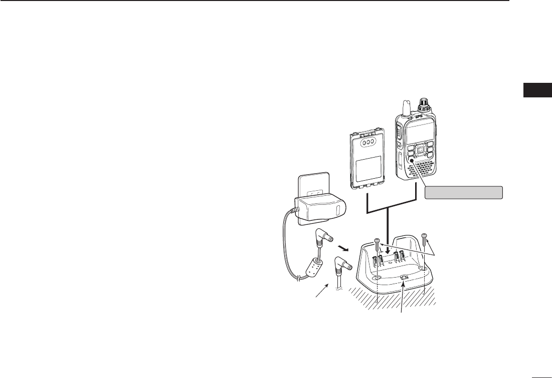
Rapid charging ■
The optional BC-202 rapidly charges of the BP-271 or BP-272
Li-ion battery packs.
Charging note D
•BesuretoturnOFFthetransceiverpower.
When the transceiver power cannot be turned OFF, detach
the battery pack from the transceiver then charge the battery
pack by itself, or charge the battery using regular charging.
Otherwise the battery pack will not be charged (the charg-
ing indicator on the BC-202 blinks orange about 10 second
after the battery pack is installed in BC-202).
•TheBC-202desktopchargercanonlychargeBP-271or
BP-272 Li-ion battery packs. Other types of rechargeable
battery, Ni-Cd or Ni-MH cannot be charged.
•Ifthechargingindicatorblinksorange,theremaybea
problem with the battery pack or charger. If this occurs, try
charging the battery pack alone, without the transceiver,
or try using the standard (non-rapid) charger. Contact your
dealer if you have problems charging a new battery pack.
•NEVER place the transceiver with the battery pack to the
desktop charger when the transceiver is connected to the
DC power supply. This may cause the charger’s malfunc-
tion and the charging indicator of the charger lights red. In
that case, disconnect the AC adapter from the charger, and
then reconnect the AC adapter to the charger.
•TheoptionalCP-23LandOPC-515Lcanbeusedinstead
of the supplied AC adapter. Connect one of these to the
[DC12-16V]jack.
• Charging period: BP-271 approximately 2.0 hours
BP-272 approximately 3.5 hours
Transceiver
(with battery pack)
Tu rn OFF the power
Battery pack
BC-202 (optional)
Desktop charger
Charging indicator
• Lights orange : While charging
• Lights green : Charging is completed
• Blinks orange : Charging error has
occured
AC Adapter
(A different type, or
no AC adapter is
supplied, depending
on the version.)
Screws*
(Self tapping screw:
3.5 × at least 30 mm)
*Purchase separately.
Using screws is
recommended to
secure the charger.
The optional OPC-515L
(for DC power source)
or CP-23L (for 12 V
cigarette lighter socket)
can be used instead of
the AC adapter.
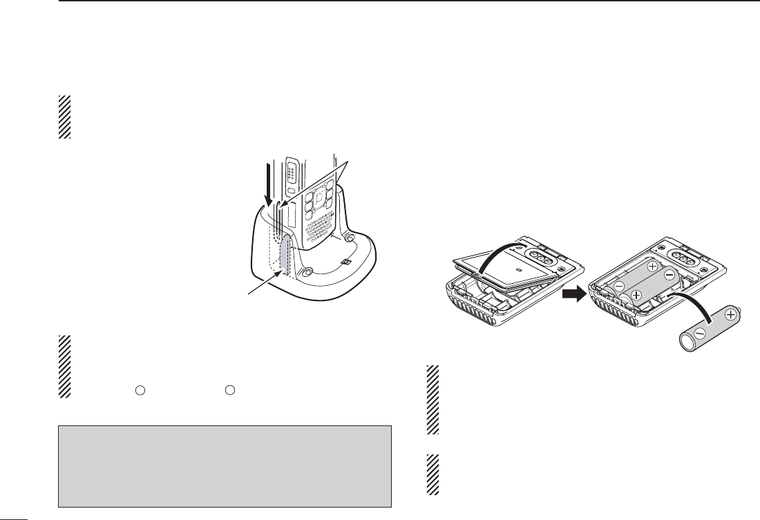
Rapid charging (Continued) ■
IMPORTANT: Battery charging caution
Ensure the tabs on the battery pack are correctly aligned
with the guide rails inside the charger.
CAUTION: When using the OPC-515L DC power cable
NEVER connect the OPC-515L to a power source using
reverse polarity. This will ruin the battery charger.
Whiteline:
+
Blackline:
–
Optional battery case ■
When using the BP-273 b at t e r y c a s e , install 3 × AA (LR6)
sizealkalinebatteries,asdescribedbelow.
Remove the battery case if it is attached. (p. 2) q
Install3×AA(LR6)sizealkalinebatteries. w
•Installonlyalkalinebatteries.
•Besuretoobservethecorrectpolarity.
Attach the battery case. (p. 2) e
•Besuretoobservethecorrectpolarity.
A built-in step-up converter in the BP-273 increases the
voltageto5.5VDC.
Approximately 100 mW of output power is possible with the
BP-273 operation. Also, the transmit output power selec-
tion is disabled.
The batteries may seem to have low capacity when used in
low temperatures, such as –10°C (+14°F) or below. Keep
the batteries warm in this case.
New2001
13
3BATTERY CHARGING
New2001
Guide rail
Tabs
NOTE: If the charging indicator blinks orange for 10 sec-
onds or more with the battery pack installed in the trans-
ceiver, try charging the BP-271 alone. You can also try
charging the BP-271 alone using the standard (non-rapid)
battery charger.

14
3
BATTERY CHARGING
New2001
3
CAUTION:
•When installing batteries, make sure they are all the
same brand, type and capacity. Also, do not mix new and
old batteries together.
•Keepthebatteryterminalsclean.It’sagoodideatoperi-
odically clean the battery terminals.
•Neverincinerateusedbatterycellssincetheinternalbat-
tery gas may cause them to rupture.
•
Never expose a detached battery case to water. If the bat-
tery case gets wet, be sure to wipe it dry before using it.
•
Never use batteries whose insulated covering is damaged.
15
3BATTERY CHARGING
New2001 New2001
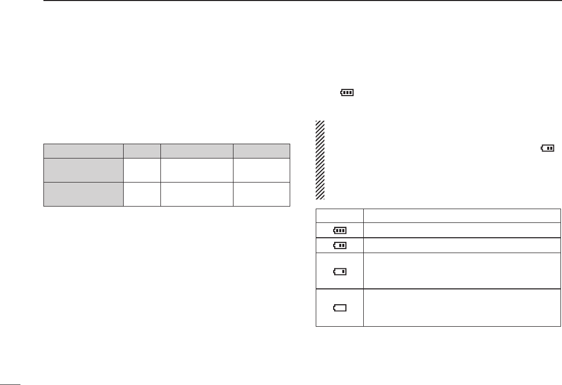
Battery information ■
Battery life D
The transceiver operates with the BP-271 or BP-272 Li-ion
battery packs, as follows.
WhenoperatingintheDVmode,theoperatingtimemaybe
shortened by one-half hour.
Battery pack
Voltage Capacity Battery life*1
BP-271 7.4V 1150 mAh (min.)
1200 mAh (typ.) ?? hrs.
BP-272 7.4V 1880 mAh (min.)
2000 mAh (typ.) ?? hrs.
*1
When the power save function is set to “Auto1,” and the operating
time is calculated under the following conditions;
TX:RX:standby=1:1:8
*2 The average operating life depends on the alkaline cells used.
Battery icon D
The “ ” battery icon appears when the BP-271 or BP-272
Li-ion battery pack is attached to the transceiver.
•WhentheBP-273batterycaseisattachedtothetrans-
ceiver, the battery icon cannot display the battery capac-
ity of the alkaline batteries. The battery icon stays “ ,”
and it does not reflect with the true battery capacity.
•The battery icon does not appear when turning power
ON after charging is completed without disconnecting the
battery charger or external DC power.
Icon Battery condition
The battery has sufficient capacity.
The battery is exhausted a little.
The battery is nearing exhaustion. Charging is
necessary. (The transceiver can be operated for
a short time.)
The battery is almost exhaustion. Charging is
necessary. (The transceiver quickly becomes
impossible to operate.)
16
3
BATTERY CHARGING
1
2
3
4
5
6
7
8
9
10
11
12
13
14
15
16
17
18
19
New2001
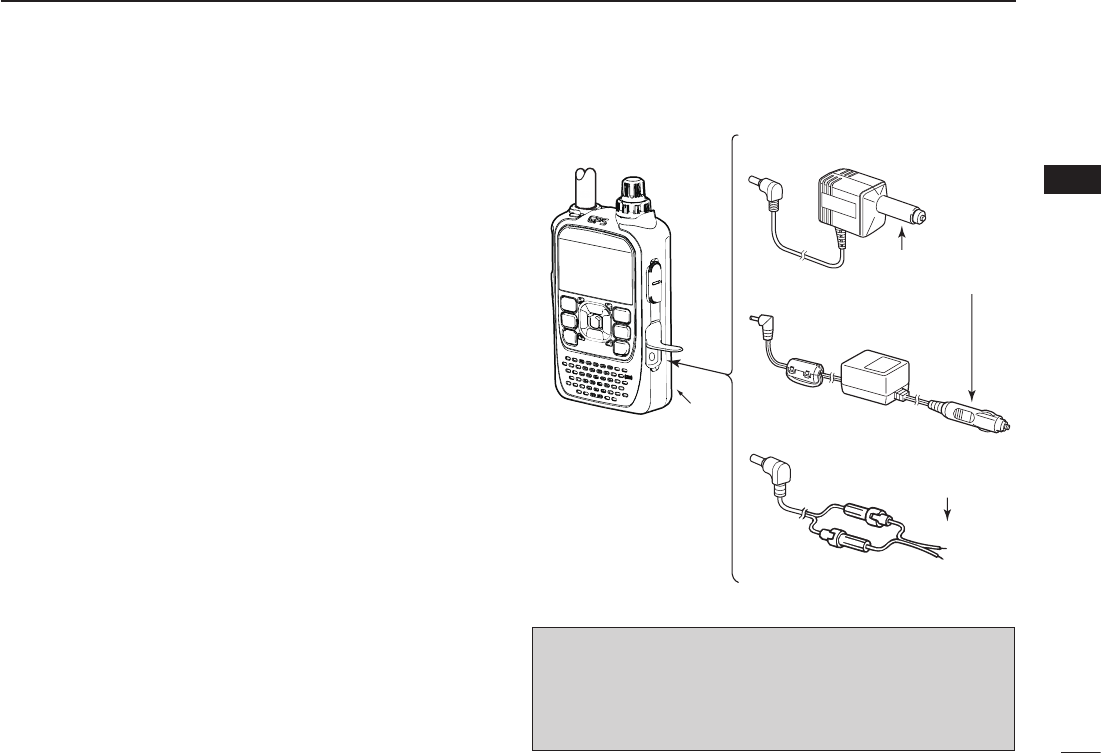
External DC power operation ■
An optional CP-12L or CP-19R cigarette lighter cable, for a
12Vcigarettelightersocket,oranOPC-254LexternalDC
power cable can be used for external power.
Operating note D
•The power supply voltage must be between 10.0–16.0 V
DC.
NEVER CONNECT OVER 16 V DC directly into the [DC IN]
jack of the transceiver.
•BE SURE to use a CP-12L, CP-19R or OPC-254L when
connecting a regulated 12 VDCpowersupply.
Use an external DC-DC converter to connect the transceiv-
er through an optional CP-12L, CP-19R or OPC-254L to a
24 VDCpowersource.
•Thevoltageoftheexternalpowersupplymustbebetween
10–16V DC when usingeitherCP-12L,CP-19RorOPC-
254L, otherwise, use the battery pack.
•Disconnect the power cables from the transceiver when
not using it. Otherwise, the vehicle battery will become ex-
hausted.
•Thepowersavefunctionisautomaticallydeactivatedwhen
using an external DC power source.
BP-217
• CP-12L (Optional)
• CP-19R (Optional)
• OPC-254L (Optional)
to a cigarette lighter
socket (12 V DC)
to a 12 V DC
(power supply)
White: +
Black: _
to
[DC IN]
Transceiver
NOTE: Up to 5 W (approximately) of maximum output
power is available when using external DC power. How-
ever,whenthesupplyvoltageexceeds14V,thebuilt-in
protection circuit activates to reduce the transmit output
power to approximately 2.5 W.
New2001New2001
17
New2001
BASIC OPERATION
4
New2001
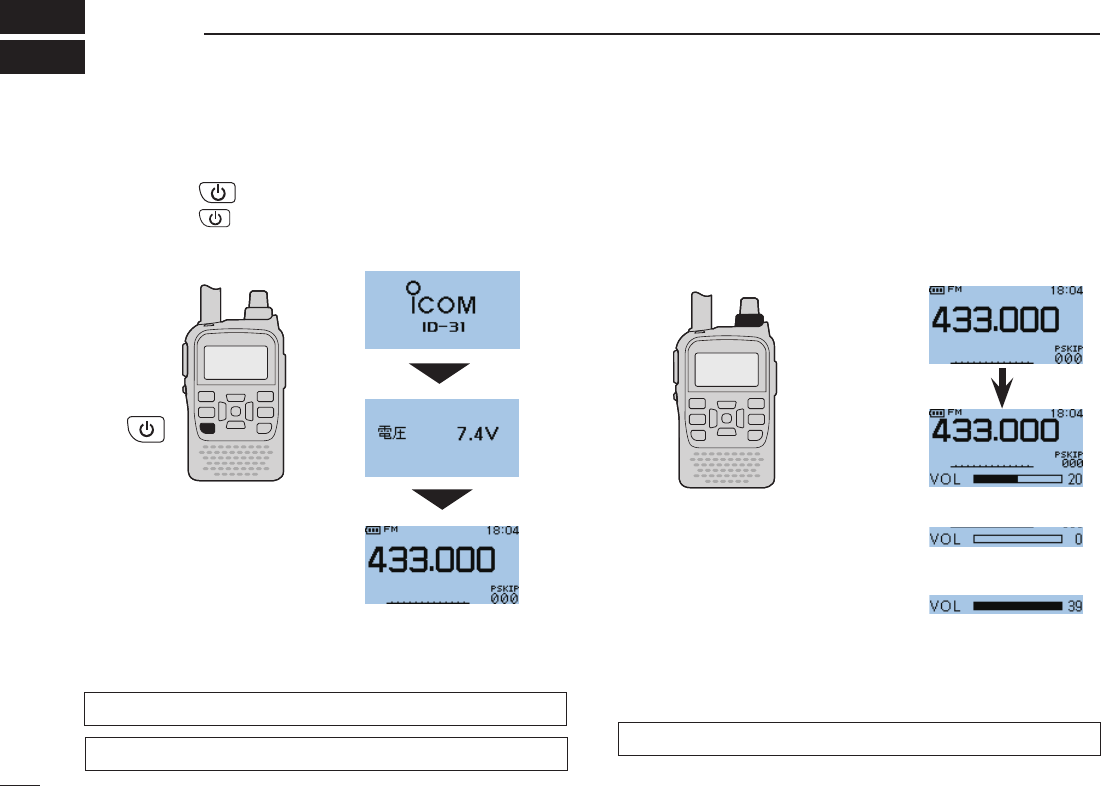
Power ON ■
Hold down ➥ for 1 second to turn ON power.
•Holddown for 1 second to turn OFF power.
•Aftertheopeningmessageandpowersourcevoltagearedis-
played, operating frequency appears.
The opening message and power source voltage display op-
tions are selectable in the DISPLAY menu.
MENU ➪DISPLAY ➪Opening Message (p. 130)
MENU ➪DISPLAY ➪Voltage Indication (p. 130)
The beep level is adjusted in the SOUNDS menu.
MENU ➪SOUNDS ➪Beep Level (p. 130)
Setting audio volume ■
Rotate[VOL] ➥
to adjust the audio level.
•Ifthesquelchisclosed,holddown[SQL]whilesettingtheaudio
level.
•Thedisplayshowsthevolumelevelwhilesetting.
[VOL]
Volumeleveldisplay
Maximum CCW
(no audio)
Maximum CW
(maximum audio)
New2001New2001New2001
18
4
BASIC OPERATION
1
2
3
4
5
6
7
8
9
10
11
12
13
14
15
16
17
18
19
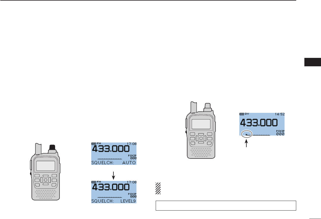
Setting squelch level ■
The squelch circuit mutes the received audio signal, depend-
ing on the signal strength. The transceiver has 9 squelch lev-
els, a continuously open setting and an automatic squelch
setting.
While holding down [SQL], rotate [DIAL] to select the ➥
squelch level.
•Whileholdingdown[SQL],rotate[DIAL]oneclicktodisplaythe
squelch level.
•“LEVEL1” isloosesquelch(forweaksignals)and“LEVEL9”is
tight squelch (for strong signals).
•“AUTO” indicates automatic level adjustment by a noise pulse
counting system.
•“OPEN”indicatesacontinuouslyopensetting.(Thisoptionisnot
selectableintheDVmode.)
Monitor function ■
This function is used to listen to weak signals without disturb-
ing the squelch setting, or having to open the squelch manu-
ally even when mute functions such as the tone squelch are
in use.
Hold down [SQL] to monitor the operating frequency. ➥
•The1stsegmentoftheS-meterblinks.
MENU ➪FUNCTION ➪Monitor (p. 125)
The [SQL] key can be set to ‘sticky’ operation in FUNC-
TION menu. See page 125 for details.
[SQL]
[DIAL]
Automatic squelch
Maximum level
[SQL]
The first segment blinks
19
4BASIC OPERATION
New2001 New2001
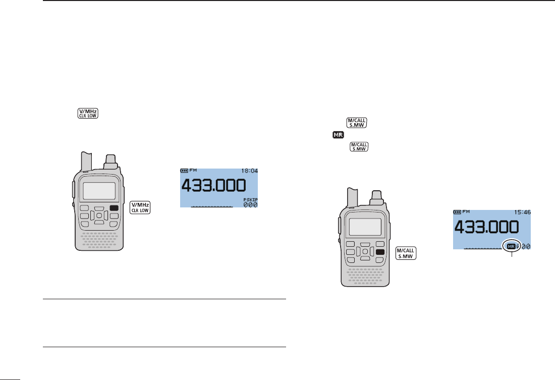
Mode selection ■
VFO mode D
VFOmodeisusedtosetthedesiredfrequency.
Push ➥(V/MHz)toselectVFOmode.
Memory mode D
Memory mode is used for operation on memory channels
which store programmed frequencies.
Push q once or twice to select memory mode.
•“
” appears when memory mode is selected.
•Push again to select Call channels. Memory mode or Call
channels are alternately selected.
• VFO mode display
• Memory mode display
Appears
What is VFO?
VFOisanabbreviationofVariableFrequencyOscillator.Fre-
quencies for both transmitting and receiving are generated
andcontrolledbytheVFO.
Rotate w[DIAL] to select a desired memory channel.
•Onlyprogrammedmemorychannelscanbeselected.
•Seep.94formemoryprogrammingdetails.
New2001
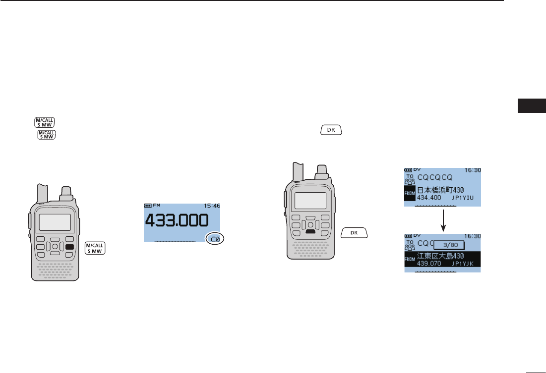
D Call channels
Call channels are used for quick recall of most-often used
frequencies.
Push q once or twice to select call channels.
•Push again to select Memory mode. Memory mode or Call
channels are alternately selected.
20
4
BASIC OPERATION
1
2
3
4
5
6
7
8
9
10
11
12
13
14
15
16
17
18
19
DR (D-STAR Repeater) mode D
DR (D-STAR Repeater) mode is used for D-STAR repeater
operation. In this mode, you can select the pre-programmed
repeaters and UR call sign easily by using [DIAL].
D-STAR is an abbreviation for Digital Smart Technologies for
Amateur Radio.
Hold down q for 1 seconds to select DR mode.
• Call channel display
• DR mode display
Rotate [DIAL] to select a desired Call channel. w
Rotate [DIAL] to select a desired access repeater. w
21
4BASIC OPERATION
New2001 New2001
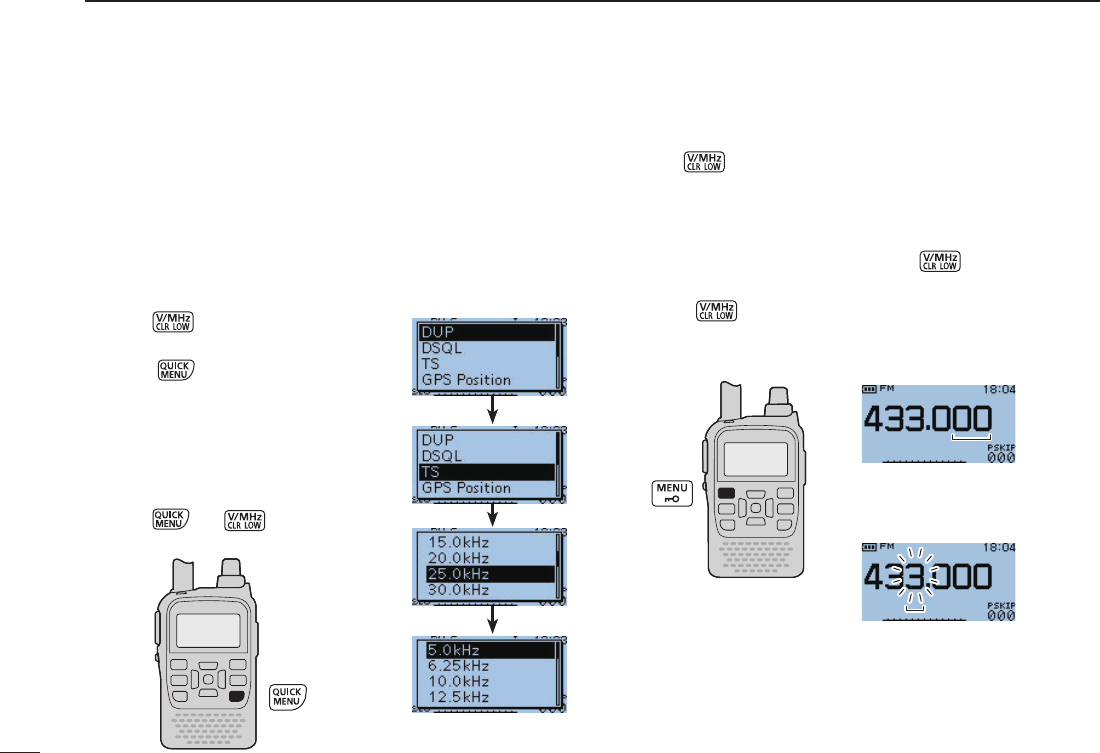
Setting a tuning step ■
The following tuning steps are selectable for the ID-31A or
ID-31E.
•5.0kHz •6.25kHz •10.0kHz •12.5kHz
•15.0kHz •20.0kHz •25.0kHz •30.0kHz
•50.0kHz •100.0kHz •125.0kHz •200.0kHz
D Tuning step selection
q Push toselectVFOmode,
if necessary.
w Push to enter the Quick
Menu screen.
e Push the Up or Down key to se-
lect the “TS” item.
r Rotate [DIAL] to select the de-
sired tuning step.
t Push (or ) to return to
VFOmode.
Setting a frequency ■
q Push toselectVFOmode,ifnecessary.
w Rotate [DIAL] to select the desired frequency.
•Thefrequencychangesaccordingtothepresettuning
steps. See the previous content to set the tuning step.
•WhenVFOmodeisselected,push then rotate [DIAL]
tochangethefrequencyin1MHzsteps.
Push again to cancel it.
5kHztuningstep
[DIAL] changes the frequency
according to the selected tuning
step.
After pushing [V/MHz] on VFO
mode, [DIAL] changes the
frequencyin1MHz steps.
New2001
22
4
BASIC OPERATION
1
2
3
4
5
6
7
8
9
10
11
12
13
14
15
16
17
18
19
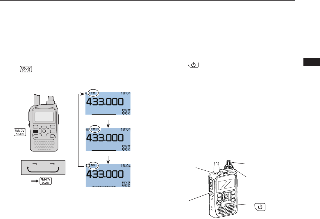
Operating mode selection ■
Operating modes are determined by the modulation of
the radio signals. The transceiver has total three operating
modes,FM,FM-NandDVmodes.
➥ Push (FM/DV)oneormoretimestoselectadesired
operating mode.
FM FM-N DV
FM mode selection
FM-N mode selection
DVmodeselection
Receiving ■
Make sure a charged battery pack (BP-271) or brand new
alkaline batteries (BP-273) are installed (pp. 2, 14).
Hold down q for 1 second to turn ON the power.
Rotate[VOL]toadjustadesiredaudiolevel.(p.16) w
•Thefrequencydisplayshowsthevolumelevelwhilesetting.
Set the receiving frequency. (p. 23) e
r Set the squelch level. (p. 17)
•Whileholdingdown[SQL],rotate[DIAL]oneclicktodisplaythe
squelch level.
•“LEVEL1” isloosesquelch(forweaksignals)and“LEVEL9”is
tight squelch (for strong signals).
•“AUTO” indicates automatic level adjustment by a noise pulse
counting system.
•Holddown[SQL]tomanuallyopenthesquelch.
tWhenasignalisreceived:
•Squelchopensandaudioisoutput.
•Tx/Rxindicatorlightswhite.
•TheS/RF-metershowstherelativesignalstrengthlevel.
q
r Set squelch level
e Set frequency
w Adjust audio level
r Push for setting
the squelch
(Push to monitor)
Tx/Rx
indicator
23
4BASIC OPERATION
New2001 New2001
Transmitting ■
CAUTION: Transmitting without an antenna will damage the
transceiver.
NOTE: To prevent interference, hold down [SQL] to listen
on the channel before transmitting.
q Set the operating frequency.
(p. 23)
•Transmission is available only on
the440MHzamateurband.
•Selectoutputpowerifdesired.See
next page for details.
w Hold down [PTT] to transmit.
•Tx/Rxindicatorlightsred.
•S/RFmetershowstheoutputpower
level.
e Speak into the microphone using
your normal voice level.
•DONOTholdthetransceivertooclosetoyourmouthorspeak
too loudly. This may distort your speech.
r Release [PTT] to return to receive.
R WARNING! NEVER transmit for long periods of time.
When the transceiver is used for prolonged transmissions
at high power or middle power, the transceiver radiates heat
to protect itself from overheating. The transceiver’s chassis
will become hot and may cause a burn.
•Topreventthetransceiver’soverheating,thedefaultsettingofthe
time-out timer function is set to 5 minutes (p. 62). Be careful when
the time-out timer function is turned OFF or set to a long time
period, and transmission is made for long periods.
DO NOT operate the transceiver in a situation that will
obstruct heat dissipation, especially if the transceiver is
operated with an external power supply. Heat dissipation
may be affected, and it may cause a burn, warp the casing
or damage the transceiver.
NOTE:Whenthetransceiverbecomeshotfromcontinuous
transmission, etc., the transceiver’s heat protection function
gradually reduces the output power to approximately 2.5 W,
then it stops transmission after that. This is done to protect
the transceiver itself until it has cooled down.
CONNECT the rated voltage range when using external
power supply.
Tx/Rx
Microphone
indicator
PTT
SQL
New2001
24
4
BASIC OPERATION
1
2
3
4
5
6
7
8
9
10
11
12
13
14
15
16
17
18
19
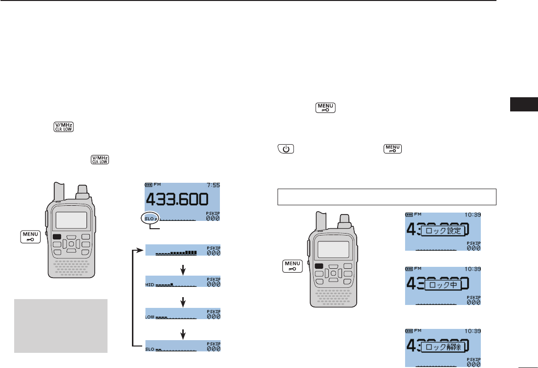
Transmit power selection ■
The transceiver has four output power levels to suit your op-
erating requirements. S-Low output power during short-range
communications may reduce the possibility of interference to
other stations and will conserve battery power.
➥
Hold down (LOW) for 1 second to toggle the transmit
output power between High (5W*), Mid (2.5 W*), Low (0.5
W*) and S-Low (0.1 W*). *approximately
•Whileholdingdown
(LOW)
, rotate [DIAL] to select the
transmit power.
Lock function ■
To prevent accidental frequency changes and unnecessary
function access, use the lock function.
Hold down ➥ (LOCK) for 1 second to turn the lock func-
tion ON or OFF.
•Whilethelockfunctionisactivatedandthelockedkeyordialis
pushed or rotated, “LOCKED” will be displayed.
• ,[VOL],[SQL],[PTT]and (LOCK) are operable while
the lock function is activated.
• Either or both the squelch control and volume control can also
be locked in the Function menu.
High power transmission
Mid power transmission
Low power transmission
S-Low power transmission
ONLY approximately
0.1 W transmission is
available while attach-
ing BP-273.
MENU ➪SET ➪FUNC ➪LOCK (p. 127)
ロック機能設定時
ロック機能設定後
操作したときの表示
ロック機能解除時
Appears

160
1
2
3
4
5
6
7
8
9
10
11
12
13
14
15
16
17
18
19
General D
• Frequency coverage : (unit: MHz)
Version TX RX
U.S.A. 420–450*1 400–479*1
AUS 420–450*2 400–479*2
EUR
KOR 430–440 430–440
UK 430–440*2 400–479*2
ITR 430–434, 435–438 430–434, 435–438
EXP 400–479*2 400–479*2
EXP-1 430–440*2 400–479*2
*
1Guaranteed 440–450 MHz only, *2Guaranteed 430–440 MHz only
• Mode :
FM, FN-N, DV
• No. of memory channels : 552
(incl. 50 scan edges and 2 call channels)
• Usable temp. range : –20°C to +60°C; –4°F to +140°F
• Tuning steps : 5, 6.25, 10, 12.5, 15, 20, 25, 30, 50,
100, 125 and 200 kHz
• Frequency stability : ±2.5 ppm
(–20°C to +60°C; –4°F to +140°F)
• Power supply : 10.0–16.0 V DC for external DC power,
or specied Icom’s battery pack
• Digital transmission speed : 4.8 kbps
• Voice coding speed : 2.4 kbps
• Current drain (at 7.4 V DC) :
TX Less than 2.5 A
RX Max. output FM Less than 350 mA (Internal speaker)
Less than 200 mA (External speaker)
DV Less than 450 mA (Internal speaker)
Less than 300 mA (External speaker)
• Antenna connector : SMA (50 W)
• Dimensions : 58(W)×95(H)×25.4(D) mm;
(projections not included) 2
9⁄32(W)×33⁄4(H)×1(D) in
• Weight (approximately) : 140 g; 4.94 oz
(without battery pack/case and ant.)
Transmitter D
• Modulation system :
FM Variable reactance freq. modulation
DV GMSK reactance freq. modulation
• Output power (at 7.4 V DC)
(Typical) : High 5.0 W, Mid. 2.5 W, Low 0.5 W,
S-Low 0.1 W
• Max. frequency deviation : ±5.0 kHz (FM wide: approx.)
±2.5 kHz (FM narrow: approx.)
• Spurious emissions : Less than –60 dBc at High/Mid.
Less than –13 dBm at Low/S-Low
• Ext. mic. impedance : 2.2 kW
15
SPECIFICATIONS
All stated specifications are subject to change without notice or obligation.

161
Receiver D
• Receive system : Double-conversion superheterodyne
• Intermediate frequencies : 46.35 MHz(1st IF)
450 kHz(2nd IF)
• Sensitivity (except spurious points):
FM (1 kHz/3.5 kHz Dev.; 12 dB SINAD) Less than –15 dBµ
DV (PN9/GMSK 4.8ksps; BER 1%) Less than –11 dBµ
• Audio output power (at 10% distortion)
Internal speaker : More than 0.4 W with a 16 Ω load
External speaker : More than 0.2 W with a 8 Ω load
• Selectivity :
FM (Wide) More than 55 dB
FM (Narrow), DV More than 50 dB
• Ext. speaker connector : 3-conductor 3.5(d) mm; (1⁄8˝)/8 W
• Spurious and image rejection ratio :
More than 60 dB
• Squelch Sensitivity (threshold, 1 kHz/3.5 kHz Dev.):
Less than –15 dBµ
15 SPECIFICATIONS
New2001