ICOM orporated 333202 UHF Mobile Transceiver User Manual IC F5020 F6020 series Instruction Manual
ICOM Incorporated UHF Mobile Transceiver IC F5020 F6020 series Instruction Manual
User Manual
INSTRUCTION MANUAL
VHF MOBILE TRANSCEIVERS
iF5120D
Series
UHF MOBILE TRANSCEIVERS
iF6120D
Series

i
IMPORTANT
READ ALL INSTRUCTIONS carefully and com-
pletely before using the transceiver.
SAVE THIS INSTRUCTION MANUAL — This
instruction manual contains important oper ating instruc-
tions for the IC-F5121D, IC-F5123D, IC-F5128D VHF MO-
BILE TRANSCEIVERS and the IC-F6121D, IC-F6123D, IC-
F6128D UHF MOBILE TRANSCEIVERS.
EXPLICIT DEFINITIONS
WORD DEFINITION
R WARNING! Personal injury, fire hazard or electric
shock may occur.
CAUTION Equipment damage may occur.
NOTE
If disregarded, inconvenience only. No risk
of personal injury, fire or electric shock.
FCC INFORMATION
• FOR CLASS B UNINTENTIONAL RADIATORS:
This equipment has been tested and found to comply with
the limits for a Class B digital device, pursuant to part 15 of
the FCC Rules. These limits are designed to provide reason-
able protection against harmful interference in a residential
installation. This equipment generates, uses and can radiate
radio frequency energy and, if not installed and used in ac-
cordance with the instructions, may cause harmful interfer-
ence to radio communications. However, there is no guaran-
tee that interference will not occur in a particular installation.
If this equipment does cause harmful interference to radio or
television reception, which can be determined by turning the
equipment off and on, the user is encouraged to try to correct
the interference by one or more of the following measures:
•Reorientorrelocatethereceivingantenna.
•Increasetheseparationbetweentheequipmentandre-
ceiver.
•Connecttheequipmentintoanoutletonacircuitdiffer-
ent from that to which the receiver is connected.
•Consultthedealeroranexperiencedradio/TVtechnician
for help.
CAUTION: Changes or modifications to this transceiver,
notexpresslyapprovedbyIcomInc.,couldvoidyourau-
thority to operate this transceiver under FCC regulations.
For Canada:
This device complies with RSS-310 of Industry Canada. Op-
eration is subject to the condition that this device does not
cause harmful interference.
Cet appareil est conforme au CNR-310 d’Industrie Canada.
Sonexploitationestautoriséesousréservequel’appareilne
causepasdebrouillagepréjudiciable.

ii
PRECAUTIONS
R WARNING! NEVER connect the transceiver to an
AC outlet. This may pose a fire hazard or result in an electric
shock.
R WARNING! NEVER connect the transceiver to a
power source of more than 16 V DC or use reverse polarity.
This could cause a fire or damage the transceiver.
R WARNING! NEVER cut the DC power cable be-
tween the DC plug and fuse holder. If an incorrect connection
is made after cutting, the transceiver might be damaged.
R WARNING! NEVER place the transceiver where
normal operation of the vehicle may be hindered or where it
could cause bodily injury.
CAUTION: NEVER allow children to touch the trans-
ceiver.
CAUTION: NEVERexposethe transceivertorain,
snow or any liquids.
USE the specified microphone only. Other microphones
have different pin assignments and may damage the trans-
ceiver.
DO NOT use or place the transceiver in areas with tem-
peratures below –30°C (–22°F) or above +60°C (+140°F), or
in areas subject to direct sunlight, such as the dashboard.
DO NOT operate the transceiver without running the ve-
hicle’s engine. The vehicle’s battery will quickly run out when
the transceiver transmits while the vehicle’s engine is OFF.
DO NOTplacethetransceiverinexcessivelydustyenvi-
ronments.
DO NOT place the transceiver against walls. This will ob-
struct heat dissipation.
DO NOT use harsh solvents such as benzine or alcohol
when cleaning, as they will damage the transceiver sur-
faces.
BE CAREFUL! The transceiver will become hot when
operating continuously for long periods of time.
Icom, Icom Inc. and the Icom logo are registered trademarks of Icom
Incorporated (Japan) in Japan, the United States, the United King-
dom,Germany,France,Spain,Russiaand/orothercountries.
All other products or brands are registered trademarks or trademarks
of their respective holders.

iii
TABLE OF CONTENTS
IMPORTANT .......................................................................... i
EXPLICIT DEFINITIONS ....................................................... i
FCC INFORMATION ............................................................. i
PRECAUTIONS .................................................................... ii
TABLE OF CONTENTS ....................................................... iii
1 PANEL DESCRIPTION ................................................1–7
■ Front panel ...................................................................1
■ Function display ...........................................................2
■ Programmable function keys ........................................3
2 BASIC OPERATION ..................................................8–14
■ Turning ON the power ..................................................8
■ Channel selection .........................................................8
■ Call procedure ..............................................................9
■ Receiving and transmitting ...........................................9
■ User Set mode ...........................................................12
■ Encryption function .....................................................13
■ Emergency transmission ............................................13
■ Stun function ..............................................................14
■ Priority A channel selection ........................................14
■
Power OFF Emergency function ........................................ 14
3 CONNECTION AND MAINTENANCE ....................15–17
■ Rear panel connection ...............................................15
■ Supplied Accessories .................................................16
■ Mounting the transceiver ............................................16
■ Antenna ......................................................................17
■ Fuse replacement ......................................................17
■ Cleaning .....................................................................17
■ Options .......................................................................17
4 SAFETY TRAINING INFORMATION .............................18
1
1
PANEL DESCRIPTION
1
2
3
4
5
6
7
8
9
10
11
12
13
14
15
16
q w
t
SpeakerFunction display (p. 2)
r
e
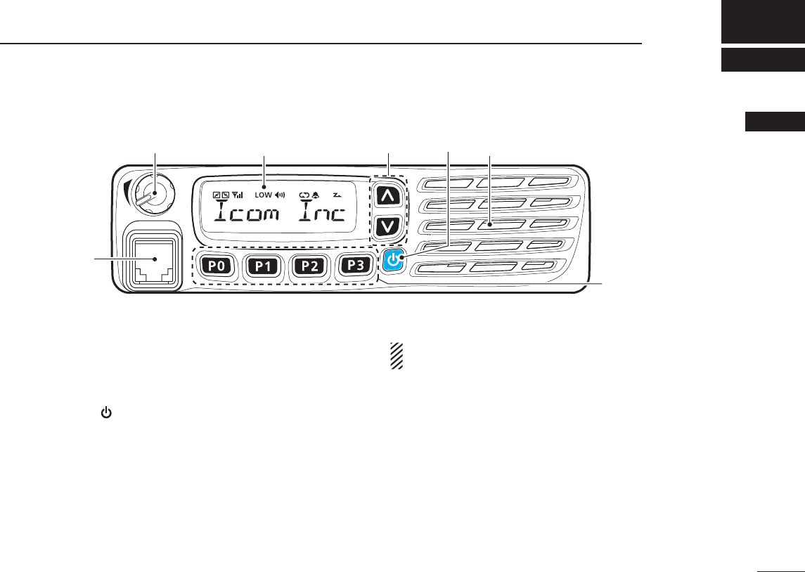
■ Front panel
q AF VOLUME CONTROL KNOB [VOL]
Rotate the knob to adjust the audio output level.
•Minimumaudiolevelispre-programmed.(p.12)
w UP/DOWN KEYS [CH Up]/[CH Down]
Push to select an operating channel, etc.
* The desired function can be assigned by your dealer. (p. 3)
e POWER KEY [ ]
Push to turn the power ON or OFF.
•ThefollowingoptionalfunctionsareavailableatpowerON:
- Automatic scan start
- Password prompt
r DEALER-PROGRAMMABLE KEYS
Required functions can be independently programmed by
your dealer. (p. 3)
t MICROPHONE CONNECTOR
Connect the supplied or optional microphone.
NEVER connect non-specified microphones. The pin assign-
ments may be different and may damage the transceiver.
D Microphone
The supplied
or optional
microphone has a PTT switch and a
hanger hook.
•ThefollowingfunctionsareavailablewhenthemicrophoneisONor
OFF hook (depending on the preprogramming):
- Automatic scan starts when you put it ON hook.
- Scan is cancelled when you take it OFF hook.
- Scan is paused when you take it OFF hook.
- Automatically selects the Priority channel when you take it OFF
hook.
- Sets to the ‘Inaudible’ mode (mute state) when you put it ON hook.
- Sets to the ‘Audible’ mode (unmute state) when you take it OFF
hook.
2
1PANEL DESCRIPTION
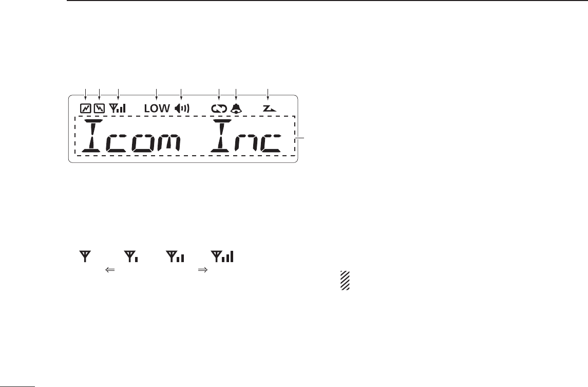
■ Function display
q TRANSMIT ICON
Appears while transmitting a signal.
w BUSY ICON
Appears while the channel is busy (receiving).
e SIGNAL STRENGTH ICON
Shows the relative receive signal strength level.
Weak Receive Signal level Strong
r LOW POWER ICON
Appears when low output power is selected.
t AUDIBLE ICON
➥ Appears when the channel is in the ‘Audible’ (unmute)
mode.
➥ Appears when a matching signal is received.
y ENCRYPTION ICON
Appears when the encryption function is activated while
operating in the digital mode.
u BELL ICON
Appears/blinkswhenamatching2/5-toneorDigitalID*is
received, depending on the preprogramming.
i SCAN ICON
➥ Blinks during a scan.
➥ Appears when a scan channel is selected.
o ALPHANUMERIC DISPLAY
Displays an operating channel number, channel name,
User Set mode contents, DTMF code, etc.
* Digital operation only
See the operating guide for details of MDC and Digital
system operations. Ask your dealer for details.
q w e r t y u i
o

3
1
PANEL DESCRIPTION
1
2
3
4
5
6
7
8
9
10
11
12
13
14
15
16
■ Programmable function keys
The following functions can be assigned to [UP], [DOWN],
[P0], [P1], [P2] and [P3] programmable function keys.
Consult your Icom dealer or system operator for details con-
cerning your transceivers programming.
CH UP AND DOWN KEYS
As described in the following topics, after pushing a pro-
grammed key, push [CH Up] or [CH Down] to select an op-
tion, setting, etc.
ZONE KEY
Pushthiskey,thenselectthedesiredzoneusing[CHUp]/
[CH Down].
What is “zone”?— Certain channels are grouped together
and assigned to a zone, according to their intended to use.
For example,‘StaffA’and‘StaffB’areassignedtoa“Busi-
ness”zone,and‘John’and‘Cindy’areassignedtoa“Pri-
vate” zone.
SCAN START/STOPKEY
➥Push to start and cancel scanning operation.
•WhenascanisstartedwiththePowerONScanorAutomatic
scan function, push this key to cancel it. The cancelled scan
resumes after the pre-programmed time period.
➥Hold down this key for 1 second to display the scan group,
then push [CH Up] or [CH Down] to select the desired
one.
SCAN ADD/DEL (TAG) KEY
➥ Push to add the channel to, or delete it from, the current
scan group.
1. Push to display the scan group, then push [CH Up] or
[CH Down] to select the desired one.
2. Push to add the channel to, or delete it from, the selected scan
group.
3.Holddownfor1secondtoexitthescanlistselectionmode.
➥ While a scan is paused on a non-priority channel, push this
key to delete the selected channel from the scan group.
Depending on the setting, the cleared channel is added
to the scan group again after the scan is cancelled.

4
1PANEL DESCRIPTION
■ Programmable function keys (Continued)
PRIO A/B KEYS
➥ Push to select the Priority A or Priority B channel.
➥ Hold down [Prio A (Rewrite)] or [Prio B (Rewrite)] for
1 second to rewrite the operating channel as Priority A or
Priority B,
MR-CH 1/2/3/4 KEYS
Push to directly select memory channel 1 to 4.
MONI (AUDI) KEY
➥PushtoturntheCTCSS(DTCS)or2/5-tonesquelchmute
ON or OFF.
•OnlyduringLMR(LandMobileRadio)operation,pushtoopen
any squelch, or deactivate any mute functions.
•OnlyduringPMR(PrivateMobileRadio)operation,pushtoacti-
vate one or two of the following functions on each channel (de-
pending on the preprogramming):
- Hold down to unmute the channel (‘Audible’ mode).
- Push to mute the channel (‘Inaudible’ mode).
- After the communication is finished, push to send a ‘reset
code’ (only 5-tone operation).
NOTE: The ‘Audible’ (unmute) mode may automatically
return to the ‘Inaudible’ (mute) mode, after the pre-pro-
grammed time period.
LIGHT KEY
Push to turn ON the backlight for about 5 seconds, when the
backlightfunctionissetto“OFF”intheUserSetmode.
LOCK KEY
➥Holddownthiskeyuntil“LOCKON”isdisplayedtoelec-
tronicallylockallprogrammablekeysexceptthefollow-
ing:
[Moni(Audi)], [Lock], [Call] (incl. Call A and Call B), [Emergency],
[Surveillance], [Siren], [Lone Worker] and [Light].
➥ When the Key Lock function is ON, hold down this key
until“LOCKOFF”isdisplayedtoturnitOFF.
LONE WORKER KEY
Push to turn the Lone Worker function ON or OFF.
•IftheLoneWorkerfunctionisturnedON,andnooperationoccurs
during the pre-programmed time period, the Emergency function is
automatically turned ON.
HIGH/LOW KEY
Push to select the transmit output power temporarily or per-
manently, depending on the preprogramming.
•Askyourdealerfortheoutputpowerlevelforeachselection.
C.TONE CH ENT KEY
Push to enter the continuous tone channel selection mode.
Then, push [CH Up] or [CH Down] to change the tone fre-
quency/codesetting.Theselectedchannelremainssetas
the continuous tone channel until another channel is desig-
nated as such.

5
1
PANEL DESCRIPTION
1
TONE/RAN CH SELECT KEY
➥ While in analog mode, push to enter the continuous tone
channel selection mode. Then push [CH Up] or [CH Down]
toselectadesiredtonefrequency/codesetting.Afterthe
selection, push this key again to set it.
➥ While in digital mode, push to enter the RAN channel se-
lection mode. Then push [CH Up] or [CH Down] to select a
desired RAN code. After the selection, push this key again
to set it.
➥Whileinmixed(digitalandanalog)mode,pushtoenter
the continuous tone channel selection mode. Then push
[CHUp]or[CHDown]toselectadesiredtonefrequency/
code setting. After setting, push this key to set it. After
that, the RAN channel selection mode appears. Select a
desired RAN code with [CH Up] or [CH Down]. After the
selection, push this key again to set it.
TALK AROUND KEY
Push to turn the Talk Around function ON or OFF.
•TheTalkAroundfunctionequalizesthetransmitfrequencytothe
receive frequency for transceiver-to-transceiver communication.
WIDE/NARROW KEY
Push to toggle the IF bandwidth between wide and narrow.
•Thewidepassbandwidthcanbeselectedfrom25.0or20.0kHz
usingtheCS-F3100D/F5120Dc l o n i n g s o f t w a r e . (PMR operation
only) Ask your dealer for details.
DTMF AUTODIAL KEY
➥ Push to enter the DTMF channel selection mode, then
push [CH Up] or [CH Down] to select the desired DTMF
channel.
➥ After selecting the DTMF channel, push again to transmit
the selected DTMF code.
RE-DIAL KEY
Push to transmit the last-transmitted DTMF code.
•TXmemoriesareclearedafterturningOFFthetransceiver.
EMERGENCY KEY
Hold down for a specified period to transmit an emergency
call.
•Ifyouwanttocanceltheemergencycall,holddownthekeyagain,
before transmitting it.

6
1PANEL DESCRIPTION
■ Programmable function keys (Continued)
CALL KEYS
Pushtotransmita2/5-toneIDcode.
•Tonecalltransmissionmaybenecessarybeforeyoucallanother
station, depending on your signalling system.
•[CallA]and/or[CallB]maybeselectablewhenyoursystemem-
ploysselective‘Individual/Group’calls.Askyourdealerwhichcall
is assigned to each key.
SURVEILLANCE KEY
Push to turn the surveillance function ON or OFF.
When a signal is received, or a key is pushed, while this
function is turned ON, the beeps do not sound and the LCD
backlight does not light.
SIREN
Hold down for 1 second to sound the siren.
This function can be used for situations other than an emer-
gencyalert,suchasasecurityalarmforexample.
•ThesirencanonlybestoppedbyturningOFFthetransceiver
power.
TX CODE ENTER KEY (PMR operation only)
Push to enter the TX code edit mode, then push [CH Up] or
[CH Down] to set a desired digit. (p. 11)
TX CODE CHANNEL SELECT KEY
➥ Push to enter the TX code channel selection mode, then
push [CH Up] or [CH Down] to set a desired channel.
(p. 10)
➥ While in the TX code channel selection mode, hold down
this key for 1 second to enter the TX code edit mode. Then
push [CH Up] or [CH Down] to set a desired digit. (p. 11)
TX CODE CHANNEL UP/DOWN KEYS
Push to select a TX code channel.
ID-MR SELECT KEY (PMR operation only)
➥ Push to recall the received ID code.
•Push this key, then select the ID code using [CH Up]/
[CH Down].
•Upto5codescanbememorized.
➥
Hold down this key for 1 second to clear the selected ID
code.
ENCRYPTION KEY
While operating in the digital mode, push to turn the encryp-
tion function ON or OFF.

7
1
PANEL DESCRIPTION
1
2
3
4
5
6
7
8
9
10
11
12
13
14
15
16
USER SET MODE KEY
➥ Hold down for 1 second to enter the User Set mode.
•WhileintheUserSetmode,pushthiskeytoselectanitem*,
and change the value or setting using [CH Up] or [CH Down].
* Selectable items may differ, depending on the preprogram-
ming.
➥
Holddownthiskeyfor1secondagaintoexittheUserSet
mode.
The User Set mode is also available via the ‘Power ON’ func-
tion. In this case, all set mode items are available. See page
12.
HOOK SCAN
When the Hook Scan function is pre-programmed, push this
key to temporarily disable the function. Push this key again to
enable the function.
Ext. CH Sel Mode KEY
PushtoturntheExt.CHSelectfunctionONorOFF.
When the function is turned ON, memory channels can be
selectedwithonlyandexternalinput.
When the function is turned OFF, memory channels can be
selected by pushing [CH Up] or [CH Down], and cannot be
externallycontrolled.
•Thisfunctionisavailablewhentheexternalunit,suchasadimmer
control is connected to the transceiver with an optional OPC-1939
or OPC-2078 cable (p. 17).
•Askyourdealerformoredetailsonexternalinputoperation.
POWER OFF EMERGENCY
While holding down this key, turn OFF the transceiver to
activate the Power OFF Emergency function. This function
makes the transceiver transmit emergency calls, even though
it appears to be powered OFF. (p. 14)
8
2BASIC OPERATION
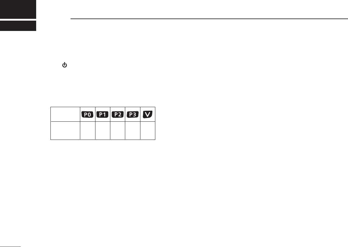
■ Turning ON the power
q Push [ ] to turn ON the power.
w If the transceiver is programmed for a start up password,
input the digit codes as directed by your dealer.
•Thekeysshownbelowcanbeusedforpasswordinput:
The transceiver detects numbers in the same block as identical.
Therefore“01234”and“56789”arethesame.
eIfthe“PASSWORD”indicationdoesnotclearafterinput-
ting 6 digits, the input code number may be incorrect. Turn
OFF the power and re-enter your password.
■ Channel selection
There are several methods to select channels, and they may
differ, depending on your system set up.
NON-ZONE TYPE:
To select the desired operating channel:
•Push[CHUp]or[CHDown].
•Pushoneof[MR-CH1]to[MR-CH4].
ZONE TYPE:
To select the desired operating channel:
Push [Zone], then push [CH Up] or [CH Down].
AUTOMATIC SCAN TYPE:
Channel setting is not necessary for this type. When turning
ON the power, the transceiver automatically starts scanning.
Scanning stops when a signal is detected.
KEY
NUMBER 0
5
4
9
3
8
2
7
1
6
9
2
BASIC OPERATION
1
2
3
4
5
6
7
8
9
10
11
12
13
14
15
16
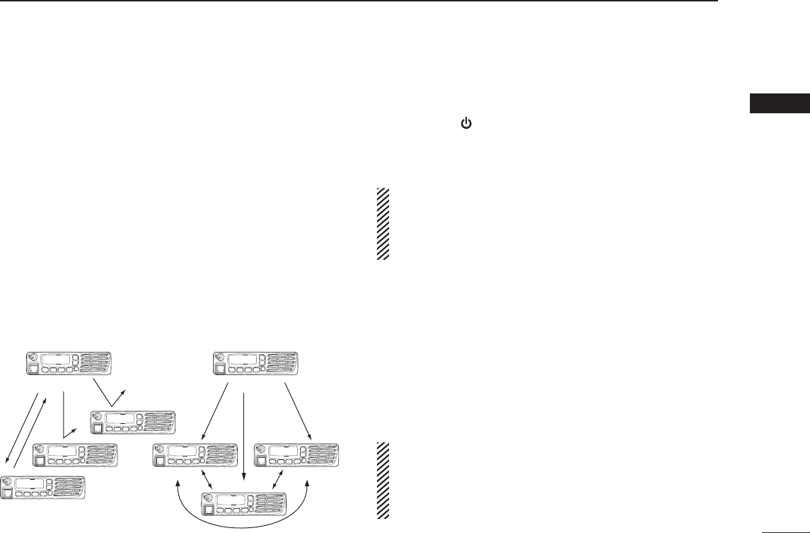
■ Call procedure
Whenyoursystememploystonesignaling(excludingCTCSS
and DTCS), a call procedure may be necessary prior to voice
transmission. The tone signalling employed may be a selective
calling system which allows you to call only specific station(s),
and prevents unwanted stations from contacting you.
qSelectthedesiredTXcodechannelor2/5-tonecode,ac-
cording to your System Operator’s instructions.
•Thismaynotbenecessary,dependingonthepreprogram-
ming.
•Refertopages10and11forselection.
w Push [Call] (assigned to one of the dealer programmable
keys).
e After transmitting, the remainder of your communication
can be carried out in the normal fashion.
Selective calling Non-selective calling
■ Receiving and transmitting
Receiving:
q Hold down [ ] for 1 second to turn ON the power.
w Push [CH Up] or [CH Down] to select a channel.
e When receiving a call, rotate [VOL] to adjust the audio out-
put level to a comfortable listening level.
NOTE:
Depending on the preprogramming, the transceiver
automatically transmits the microphone audio for the specified
time period*, when a matched RX code signal is received.
•HM-148GorHM-152h a n d m i c r o p h o n e is required.
* Depending on the preprogramming. Ask your dealer for details.
Transmitting:
Wait for the channel to become clear to avoid interference.
q Take the microphone OFF hook.
•The‘Audible’modeisselected.
•Aprioritychannelmaybeautomaticallyselected.
w Wait for the channel to become clear.
•
The channel is busy when the BUSY icon appears on the LCD.
e While holding down [PTT], speak into the microphone at
your normal voice level.
r Release [PTT] to return to receive.
IMPORTANT:Tomaximizethereadabilityofyoursignal;
1. Pause briefly after pushing [PTT].
2. Hold the microphone 5 to 10 cm (2 to 4 inches) from
your mouth, then speak into the microphone at a normal
voice level.

10
2BASIC OPERATION
■ Receiving and transmitting (Continued)
D Transmitting notes
• Transmit inhibit function
The transceiver has several inhibit functions which restrict
transmission under the following conditions:
-Thechannelisinthe‘Inaudible’(mute)mode;“ ” (Audible
icon) does not appear.
- The channel is busy. However, depending on the prepro-
grammed settings, you can transmit when the call includes
an unmatching (or matching) CTCSS (DTCS), RAN code,
or Individual or Talkgroup ID.
- The selected channel is a ‘receive only’ channel.
• Time-out timer
Ifcontinuoustransmissionexceedsthepre-programmed
time-out timer limit, the transmission is cut off.
• Penalty timer
After the transmission is cut off by the time-out timer, trans-
mission is further inhibited for the pre-programmed penalty
timer period.
• PTTID call
The transceiver automatically sends the 5-tone, DTMF, BIIS
or digital ANI ID code when [PTT] is pushed (at the begin-
ningofthetransmission),and/orwhenitisreleased(atthe
end of transmission), depending on the preprogramming.
A PTTID call also be made with the MDC 1200 signaling
system.
D TX code channel selection
If the transceiver has a key assigned to [TX Code CH Select],
the dysplay can be toggled between the operating channel
number (or name) and TX code channel number (or name).
When the TX code channel number (or name) is displayed,
[CH Up] or [CH Down] selects the TX code channel.
USING [TX CODE CH SELECT] KEY:
q Push [TX Code CH Select]— a TX code channel number
(or name) appears.
w Push [CH Up] or [CH Down] to select the desired TX code
channel.
e After selecting, push [TX Code CH Select] to set.
•Returntothestand-bymode.
r Push [Call] to transmit the selected TX code.
USING [TX CODE CH UP]/[TX CODE CH DOWN] KEY:
If the transceiver has a key assigned to [TX Code CH Up] or
[TX Code CH Down], the programmed TX code channel can
be directly selected when pushed.

11
2
BASIC OPERATION
1
2
3
4
5
6
7
8
9
10
11
12
13
14
15
16
D TX code number edit (PMR operation only)
If the transceiver has a key assigned to [TX Code CH Select]
or [TX Code Enter], TX code contents can be edited within
the allowable digits.
USING [TX CODE CH SELECT] KEY:
q Push [TX Code CH Select] to enter the TX code channel
selection mode.
•SelectthedesiredchannelbeforeenteringtheTXcodechannel
selection mode, if necessary.
w Hold down [TX Code CH Select] for 1 second to enter the
TX code edit mode.
•Thedigittobeeditedblinks.
e Push [TX Code CH Select] to select the desired digit to be
edited.
r Push [CH Up] or [CH Down] to select the desired digit.
t Push [TX Code CH Select] to set. The digit to the right will
automatically blink.
y Repeat r and t to edit all allowable digits.
u After editing, push [TX Code CH Select] to set.
•Returntothestand-bymode.
i Push [Call] to transmit.
USING [TX CODE ENTER] KEY:
q Push [TX Code Enter] to enter the TX code edit mode.
•Thedigittobeeditedblinks.
w Push [TX Code Enter] to select the desired digit to be ed-
ited.
e Push [CH Up] or [CH Down] to select the desired digit.
r Push [TX Code Enter] to set. The digit to the right will au-
tomatically blink.
t Repeat e and r to edit all allowable digits.
y After editing, push [TX Code Enter] to set.
•Returntothestand-bymode.
u Push [Call] to transmit.
D DTMF transmission
If the transceiver has a key assigned to [DTMF Autodial], the
automatic DTMF transmission function is available. Up to 8
DTMF channels are selectable.
q Push [DTMF Autodial]— a DTMF channel appears.
w Push [CH Up] or [CH Down] to select the desired DTMF
channel.
e Push [DTMF Autodial] to transmit the DTMF code.
12
2BASIC OPERATION
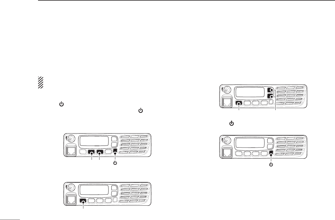
■ User Set mode
The User Set mode can be accessed with the ‘Power ON’
function. In this case, all set mode items are selectable.
The User Set mode allows you to set seldom-changed set-
tings,andyoucan“customize”thetransceiveroperationto
suit your preferences and operating style.
NOTE: While in the User Set mode, [Up], [Down] and [P0]
activate regardless of the assigned key functions.
Entering the User Set mode:
q Push [ ] to turn OFF the power.
w While holding down [P1] and [P2], push [ ] to turn ON the
power.
•Holddown[P1]and[P2]continuouslyuntil“SETMODE”ap-
pears on the display.
[P1] [P2] [ ]
e Hold down [P0] for 1 second to enter the User Set mode.
•ToexittheUserSetmode,holddown[P0]for1secondagain.
[P0]
r Push [P0] several times to select the appropriate item,
then push [Up] or [Down] to set the desired level or set-
ting.
•SelectableSetmodeitemsareBacklight, Beep ON/OFF, Beep
Level, Ringer Level, SQL Level, AF Min Level, Mic Gain, Bat-
tery Voltage, Horn, Signal Moni, Lone Worker and System
Info.
[P0] [Up]/[Down]
t Hold down [ ] for 1 second to turn OFF the power, then
ON again to return to the normal operating mode.
[ ]
The User Set mode can also be selected using a program-
mable key. Please refer to the [User Set Mode] section on
page 6 for instructions on how to use the key assigned to the
User Set mode.
[User Set Mode] can be used for the quick item selection.
Set“Enable”fortheoftenuseditemswiththeCS-F3100D/
F5120D c l o n i n g s o f t w a r e .

13
2
BASIC OPERATION
2
■ Emergency transmission
When [Emergency] is held down for the specified time pe-
riod*, the emergency signal is transmitted on the specified
emergency channel once or repeatedly.
When no emergency channel is specified, the call is transmit-
ted on the operating channel.
The repeat emergency signal is automatically transmitted
until you turn OFF the power.
Depending on the preprogramming, receiving a matching
5-tone code cancels the transmission.
If you want to cancel the Emergency function, hold down
[Emergency] for the pre-programmed time period again be-
fore transmitting the call.
If your transceiver is programmed for Silent operation, you
can transmit emergency calls without the beep sounding and
the LCD indication change.
IMPORTANT: It is recommended to set an emergency
channel individually to provide the certain emergency call
operation.
D NOTES
Depending on the preprogramming, the following functions
are automatically activated. Ask your dealer for details.
• Auto TX function
After the emergency call transmission, audio from the micro-
phone is automatically transmitted for a specified time pe-
riod.*
•TheHM-148GorHM-152handmicrophoneisrequired.
• Auto RX function
After the emergency call transmission, the transceiver stands
by in the audible mode for the specified time period.*
* Depending on the preprogramming. Ask your dealer for de-
tails.
■ Encryption function
The encryption function provides private communication be-
tween stations while operating in the digital mode.
q Push [Encryption] to turn ON the encryption function.
•“ ” (Encryption icon) appears.
w Push [Encryption] again to turn OFF the encryption func-
tion.
•“ ” disappears.

14
2BASIC OPERATION
■ Stun function
Thedispatchercansenda2/5-tonesignalthatwillstun,kill
or revive your transceiver.
When the Stun ID is received, a beep sounds*, and the trans-
ceiver becomes unusable. Receiving a Revive command or
entering password* (p. 8) is necessary to operate the trans-
ceiver again in this case.
When the Kill ID is received, a beep sounds*, and the trans-
ceiver becomes unusable (the transceiver switches to the
cloning required condition). Cloning the transceiver is neces-
sary to operate the transceiver again in this case.
* Depending on the preprogramming. Ask your dealer for de-
tails.
See the operating guide for details of the Stun function
with the MDC and Digital system operations. Ask your
dealer for details.
■
Power OFF Emergency function
When the transceiver has a key assigned to Power OFF
Emergency, you can use the function.
This function makes the transceiver transmit emergency
calls, even though it appears to be powered OFF.
To activate the Power OFF Emergency function, turn the
power OFF while holding down [Power OFF Emergency].
Whenthefunctionisactivated,anykeyoperation,theON/
OFF Hook and Lone Worker functions become invalid. The
beep, display and speaker are turned OFF as well.
On the other hand, the transceiver can transmit emergency
calls according to the pre-programmed emergency settings.
Depending on the pre-programmed settings, the Remote
Monitor function can also be used (digital operation only).
To cancel the Power OFF Emergency function and restore
the transceiver, turn the power ON.
■ Priority A channel selection
When one of the following operations is performed, the trans-
ceiver automatically selects the Priority A channel.
• Turning ON the power
The Priority A channel is selected each time the transceiver
power is turned ON.
• Auto Reset
The Priority A channel is selected when the Auto Reset
timer ends.
• OFF hook
The Priority A channel is selected when you take the micro-
phone OFF hook.
15
3
CONNECTION AND MAINTENANCE
1
2
3
4
5
6
7
8
9
10
11
12
13
14
15
16
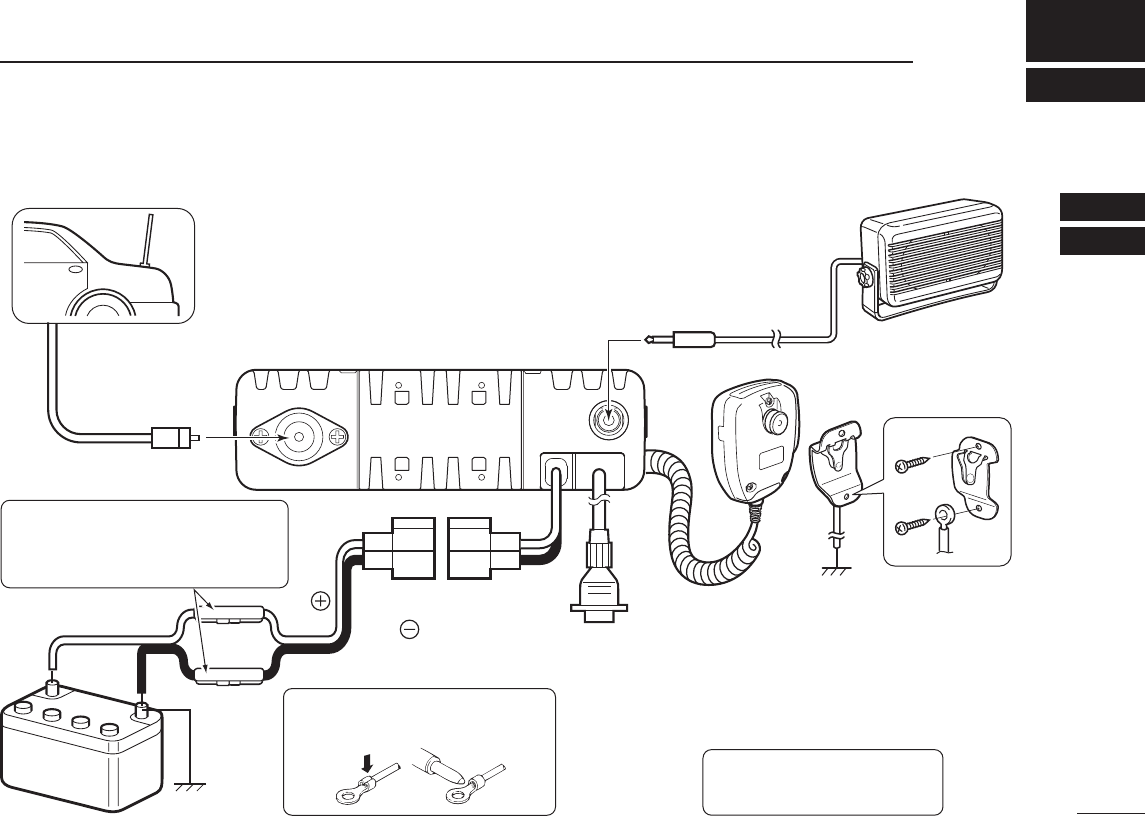
e
r
Antenna
Black
Red
12V
Battery
Solder
Crimp
NOTE: Use the terminals as shown
for the cable connections.
q ANTENNA CONNECTOR
Connect to an antenna. Ask your
dealer about antenna selection
and placement.
qw
w EXTERNAL SPEAKER JACK
Connect to a 4 to 8 ø external speaker.
e MICROPHONE HANGER
Connect the supplied micro-
phone hanger to the vehicle’s
ground for microphone on/off
hook functions. (See page 2)
r
OPTIONAL CABLE (OPC-1939, OPC-2078
)
t
t DC POWER RECEPTACLE
Connect to a 12 V DC battery.
Pay attention to polarities.
Optional speaker
Connect an external modem,
dimmer control, etc.
R WARNING! NEVER connect
to a 24 V battery. This could
damage the transceiver.
R WARNING! NEVER remove the
fuse-holders from the DC power cable.
(Depending on version, the fuse holder
may not be attached to the black cable.)
■ Rear panel connection
16
3CONNECTION AND MAINTENANCE
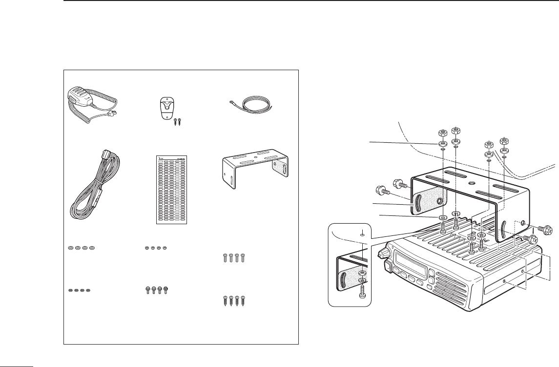
■ Supplied Accessories ■ Mounting the transceiver
The universal mounting bracket supplied with your trans-
ceiver allows overhead mounting.
•Mountthetransceiversecurelywiththe4suppliedscrews
to a thick surface which can support more than 1.5 kg
(3.3 lb).
Flat washer
Felt*
Spring washer
When using
self-tapping screws *Felt reduces the effects of vibration.
Microphone Microphone hanger
and screw set
Microphone
hanger cable
DC power cable
Flat washers
Spring washers Bracket bolts
Mounting screws
(5×12)
Self-tapping screws
(5×20)
Nuts
Function name
stickers*
Used for labelling the programmable function
keys according to their assinged functions.
*
Mounting bracket
17
3
CONNECTION AND MAINTENANCE
1
2
3
4
5
6
7
8
9
10
11
12
13
14
15
16
■ Antenna
A key element in the performance of any communication sys-
tems is its antenna. Contact your dealer for more information
regarding antennas and how to install them.
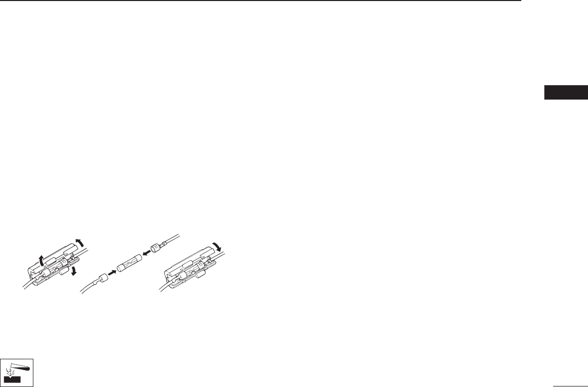
■ Fuse replacement
A fuse is installed in each fuse holder of the supplied DC
power cable*. If a fuse blows or the transceiver stops func-
tioning, track down the source of the problem if possible, re-
paire it and then replace the damaged fuse with a new rated
one.
*Depending on version, only one fuse holder may be attached.
❑Fuserating:10A(foronefuseholder)/20A(forTwofuseholders)
USE the applicable fuse only.
■ Cleaning
If the transceiver becomes dusty or dirty, wipe it clean with a
soft, dry cloth.
DO NOT use harsh solvents such as benzine or
alcohol, as they will damage the transceiver sur-
faces.
■ Options
• OPC-1132A/OPC-347 d c p o w e r c a b l e
Two fuse holders are attached. USE the 20 A fuse only.
OPC-1132A: 3 m (9.8 ft)
OPC-347: 7 m (23 ft)
• OPC-1939/OPC-2078 a c c c a b l e
Allowsyoutoconnecttoanexternalterminal.
OPC-1939: D-sub 15-pin, OPC-2078: D-sub 25-pin
•HM-152/HM-152T/HM-148G h a n d m i c r o p h o n e
HM-152 : Hand microphone
HM-152T : DTMF microphone
HM-148G : Self ground heavy duty microphone
•SM-26 d e s k t o p m i c r o p h o n e
•SP-22/SP-30 e x t e r n a l s p e a k e r
Input impedance : 4 ø
SP-22 :Ratedinput;5W,Max.input;7W
SP-30 :Ratedinput;20W,Max.input;30W
Approved Icom optional equipment is designed for optimal perfor-
mance when used with an Icom transceiver.
Icom is not responsible for the destruction or damage to an Icom
transceiver in the event the Icom transceiver is used with equipment
that is not manufactured or approved by Icom.

4SAFETY TRAINING INFORMATION
18
WARNING
Your Icom radio generates RF electromagnetic en-
ergy during transmit mode. This radio is designed
for and classified as “Occupational Use Only”,
meaning it must be used only during the course of
employment by individuals aware of the hazards,
and the ways to minimize such hazards. This radio
is NOT intended for use by the “General Popula-
tion” in an uncontrolled environment.
•ForcompliancewithFCCandIndustryCanadaRFExposureRe-
quirements, the transmitter antenna installation shall comply with
the following two conditions:
1.Thetransmitterantennagainshallnotexceed0dBi.
2. IC-F5121D:
The antenna is required to be located outside of a vehicle and
kept at a distance of 45 centimeters or more between the trans-
mitting antenna of this device and any persons during operation.
For small vehicle as worst case, the antenna shall be located on
the roof top at any place on the centre line along the vehicle in
order to achieve 45 centimeters separation distance. In order to
ensure this distance is met, the installation of the antenna must
be mounted at least 45 centimeters away from the nearest edge
ofthevehicleinordertoprotectagainstexposuretobystanders.
2. IC-F6121D:
The antenna is required to be located outside of a vehicle and
kept at a distance of 37 centimeters or more between the trans-
mitting antenna of this device and any persons during operation.
For small vehicle as worst case, the antenna shall be located on
the roof top at any place on the centre line along the vehicle in
order to achieve 37 centimeters separation distance. In order to
ensure this distance is met, the installation of the antenna must
be mounted at least 37 centimeters away from the nearest edge
ofthevehicleinordertoprotectagainstexposuretobystanders.
3. IC-F5121D:
Transmit only when people outside the vehicle are at least the
recommended minimum distance of 100 centimeters away from
the properly installed antenna. This separation distance will en-
sure that there is sufficient distance from a properly installed
externally-mountedantennatosatisfytheRFexposurerequire-
mentsintheapplicableRFexposurecompliancestandards.
3. IC-F6121D:
Transmit only when people outside the vehicle are at least the
recommended minimum distance of 82 centimeters away from
the properly installed antenna. This separation distance will en-
sure that there is sufficient distance from a properly installed
externally-mountedantennatosatisfytheRFexposurerequire-
mentsintheapplicableRFexposurecompliancestandards.

SAFETY TRAINING INFORMATION 4
1
2
16
15
14
13
12
11
10
9
8
7
6
5
4
19
3
CAUTION
To ensure that your exposure to RF electromag-
netic energy is within the FCC allowable limits for
occupational use, always adhere to the following
guidelines:
•DO NOT operate the radio without a proper antenna attached, as
thismaydamagetheradioandmayalsocauseyoutoexceedFCC
RFexposurelimits.Aproperantennaistheantennasuppliedwith
this radio by the manufacturer or an antenna specifically authorized
by the manufacturer for use with this radio.
•DO NOTtransmitformorethan50%oftotalradiousetime(“50%
duty cycle”). Transmitting more than 50% of the time can cause
FCCRFexposurecompliancerequirementstobeexceeded.The
radioistransmittingwhenthe“transmitindicator”appearsonthe
LCD.Youcancausetheradiototransmitbypressingthe“PTT”
switch.
Electromagnetic Interference/Compatibility
During transmissions, your Icom radio generates RF energy that
can possibly cause interference with other devices or systems. To
avoid such interference, turn OFF the radio in areas where signs are
posted to do so. DO NOT operate the transmitter in areas that are
sensitive to electromagnetic radiation such as hospitals, aircraft, and
blasting sites.

1-1-32 Kamiminami, Hirano-ku, Osaka 547-0003, Japan
A-6903H-1EX-0a
Printed in Japan
© 2010–2011 Icom Inc.
Printed on recycled paper with soy ink.

AVERTISSEMENT
Votre radio Icom produit une énergie
électromagnétique de radiofréquences
(RF), en mode de transmission. Cette
radio est conçue pour un «usage pro-
fessionnel seulement» et classée
comme tel, ce qui signifie qu’elle doit
être utilisée uniquement dans le cadre
d’un travail par des personnes
conscientes des dangers et des mesu-
res visant à minimiser ces dangers.
Elle N’EST PAS conçue pour une «uti-
lisation grand public», dans un envi-
ronnement non contrôlé.
• An de satisfaire aux exigences de la FCC et d’Industrie
Canada en matière d’exposition aux RF, il est néces-
saire que l’antenne soit installée conformément aux trois
conditions suivantes:
1. Le gain de l’antenne du radio émetteur ne doit pas
dépasser 0dBi.
2. IC-F5121D:
Il faut que l’antenne émettrice de cet appareil soit pla-
cée à l’extérieur d’un véhicule et tenue éloignée d’au
moins 45 centimètres de toute personne pendant le
fonctionnement. Dans le pire des cas, pour un petit vé-
hicule, l’antenne doit être placée sur le toit, n’importe
où dans l’axe central du véhicule, an de respecter
une distance de 45 cm du bord le plus rapproché du
véhicule et ainsi éviter que les personnes présentes
soient exposées.
2. IC-F6121D:
Il faut que l’antenne émettrice de cet appareil soit pla-
cée à l’extérieur d’un véhicule et tenue éloignée d’au
moins 37 centimètres de toute personne pendant le
fonctionnement. Dans le pire des cas, pour un petit vé-
hicule, l’antenne doit être placée sur le toit, n’importe
où dans l’axe central du véhicule, an de respecter
une distance de 37 cm du bord le plus rapproché du
véhicule et ainsi éviter que les personnes présentes
soient exposées.
3. IC-F5121D:
Émettre uniquement lorsque les personnes à l’exté-
rieur du véhicule se trouvent à au moins la distance
minimale recommandée de 100 cm de l’antenne cor-
rectement installée. Cette distance de sécurité assu-
rera que les personnes soient placées sufsamment
loin d’une antenne correctement xée à l’extérieur
pour satisfaire aux exigences en matière d’exposition
aux RF, en vertu des normes de conformité applica-
bles.
3. IC-F6121D:
Émettre uniquement lorsque les personnes à l’exté-
rieur du véhicule se trouvent à au moins la distance
minimale recommandée de 82 cm de l’antenne correc-
tement installée. Cette distance de sécurité assurera
que les personnes soient placées sufsamment loin
d’une antenne correctement xée à l’extérieur pour
satisfaire aux exigences en matière d’exposition aux
RF, en vertu des normes de conformité applicables.
MISE EN GARDE
Afin de vous assurer que votre exposi-
tion à une énergie électromagnétique
de RF se situe dans les limites permi-
ses par la FCC pour une utilisation
grand public, veuillez en tout temps
respecter les directives suivantes:
• NE PAS faire fonctionner la radio sans qu’une an-
tenne appropriée y soit xée, car ceci risque d’endom-
mager la radio et causer une exposition supérieure
aux limites établies par la FCC. L’antenne appropriée
est celle qui est fournie avec cette radio par le fabri-
cant ou une antenne spécialement autorisée par le
fabricant pour être utilisée avec cette radio.
• NE PAS émettre pendant plus de 50 % du temps total
d’utilisation de l’appareil («50 % du facteur d’utilisa-
tion»). Émettre pendant plus de 50 % du temps total
d’utilisation peut causer une exposition aux RF supé-
rieure aux limites établies par la FCC. La radio est en
train d’émettre lorsque le témoin du mode de trans-
mission s’afche sur l’écran ACL. La radio émettra si
vous appuyez sur le bouton du microphone.
Interférence électromagnétique et compatibilité
En mode de transmission, votre radio Icom produit de
l’énergie de RF qui peut provoquer des interférences avec
d’autres appareils ou systèmes. Pour éviter de telles inter-
férences, mettez la radio hors tension dans les secteurs
où une signalisation l’exige. NE PAS faire fonctionner
l’émetteur dans des secteurs sensibles au rayonnement
électromagnétique tels que les hôpitaux, les aéronefs et
les sites de dynamitage.
INFORMATION EN MATIÈRE DE SÉCURITÉ
A-6903H-3EX
Imprimé au Japon
© 2011 Icom Inc.