ICOM orporated 348400 Dual Band Transceiver User Manual
ICOM Incorporated Dual Band Transceiver
UserManual.wiki
>
ICOM orporated
>
348400 User Manual
User Manual
Navigation menu
Upload a User Manual
Namespaces
Wiki Guide
HTML
PDF
Info
Views
User Manual
Discussion / Help
Navigation
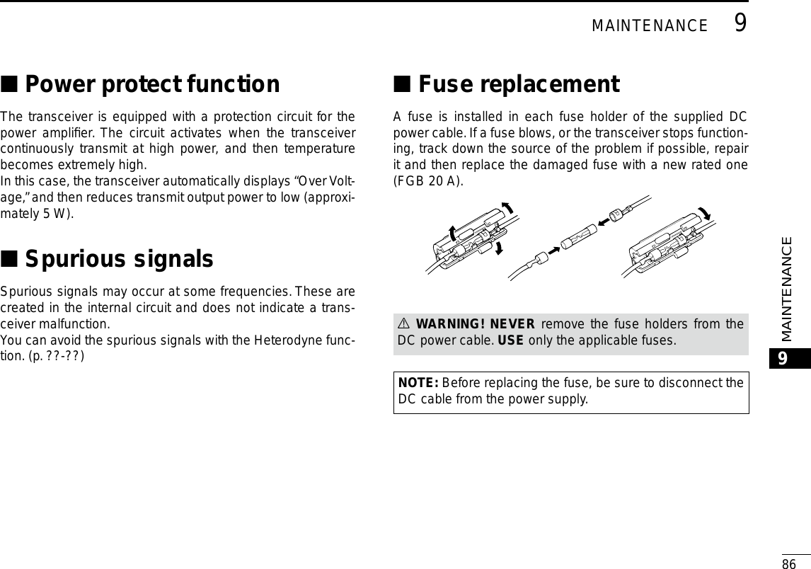
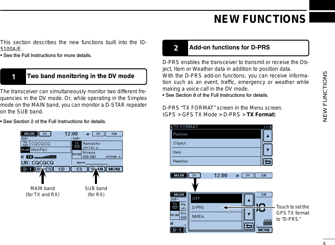
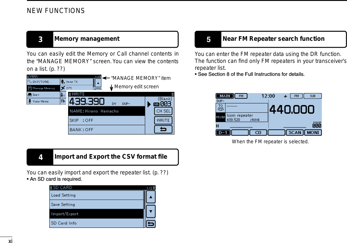
![New2001New2001iiSUPPLIED ACCESSORIESThe following accessories are supplied with the transceiver.DC power cable Controller cable (3.5 m:11.4 ft) Microphone (HM-207)CD( Instruction manual [Full instructions])Operating guide( Includes the CS-5100 CLONING SOFTWARE)Spare fuse(FGB 20 A)Microphone hanger DWhen using the GPS receiver• GPS signals cannot pass through metal objects. When us-ing the ID-5100A or ID-5100E inside a vehicle, you may not receive GPS signals. We recommend you use it near a win-dow. Please avoid the areas: 1. where it will block the driver’s view. 2. where the air bags could deploy. 3. where it becomes a driving obstacle.• The Global Positioning System (GPS) is built and operated by the U.S. Department of Defence. The Department is re-sponsible for accuracy and maintenance of the system. Any changes by the Department may affect the accuracy and function of the GPS system.• When the GPS receiver is activated, please do not cover the remote controller with anything that will block the satel-lite signals.• The GPS receiver may not work if used in the following loca-tions: 1. Tunnels or high-rise buildings 2. Underground parking lots 3. Under a bridge or viaduct 4. In remote forested areas 5. Under bad weather conditions (rainy or cloudy day)IMPORTANT NOTES](https://usermanual.wiki/ICOM-orporated/348400/User-Guide-2227051-Page-3.png)
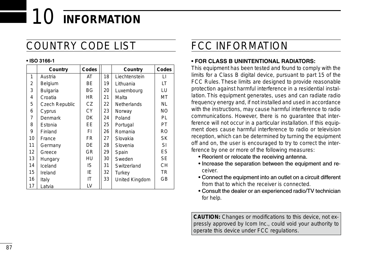
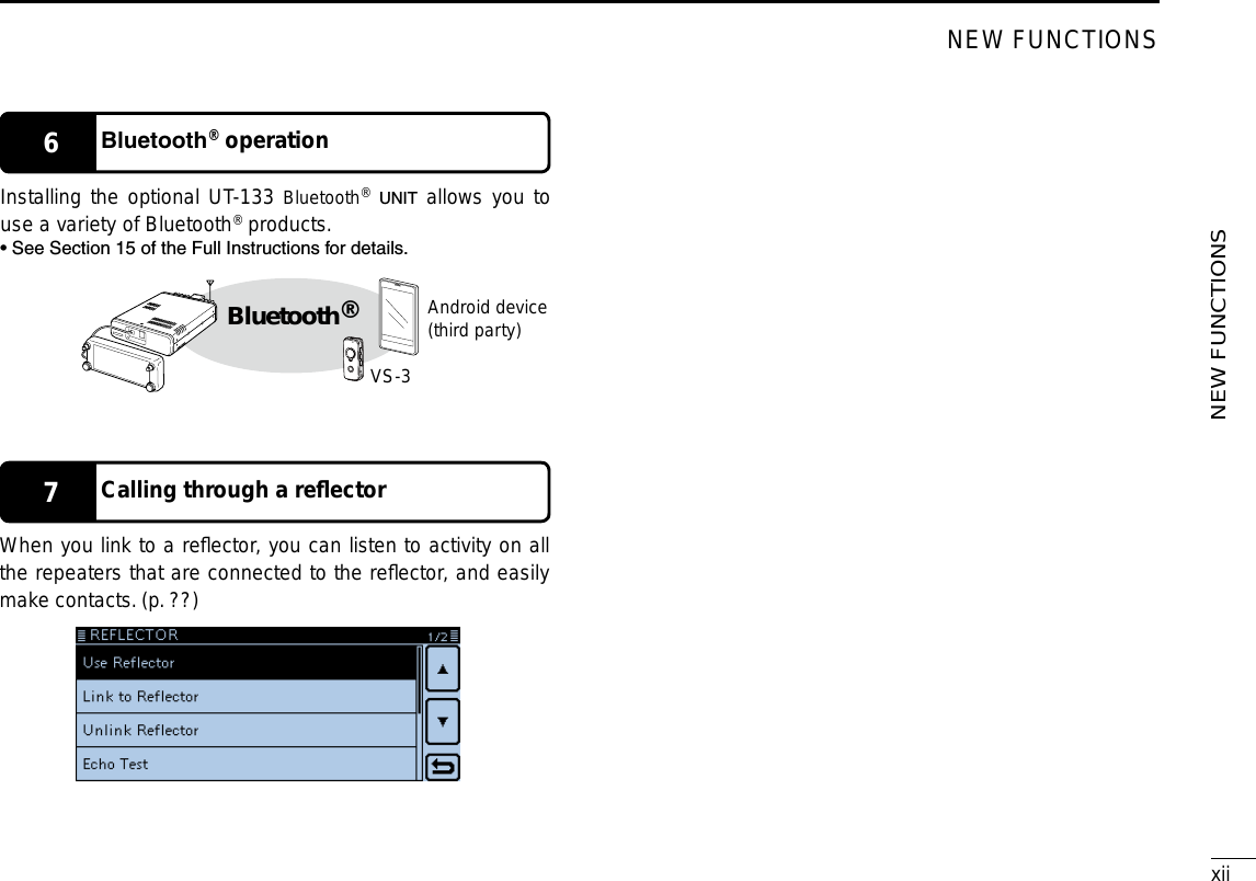
![ivID-5100Function menu selection: Displays the Function menu list: Displays the QUICK Menu: Function menuoperations• The following operations are examples.Sets MAIN band to the right side: Sets MAIN band to the right side: Dual or Single band display selection: • In the Single band, touch [B] to set the B band as the MAIN band.Displays the DR screen: • D-STAR settings can easily be made.Home CH selection: • Selects the Home CH that you set in the QUICK Menu.Home CH setting: Displays the Menu screen: Cancels “MHz” tuning: Tuning step selection: Displays the MemoryWrite window: Writes to a blankCH: Scan typeselection: Starts a scan: • The last used scan starts.Dual or Single band display selection: Operating mode selection: “MHz” tuning selection: Operating band selection: TX power selection: • MAIN band: Used for TX or radio’s settings• SUB band: Used for the Dualwatch operationABOUT THE TOUCH SCREEN (Continued)Displays the Monitor function: Sets the Mode:](https://usermanual.wiki/ICOM-orporated/348400/User-Guide-2227051-Page-5.png)
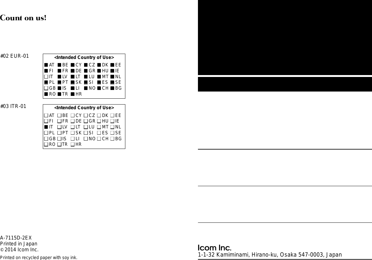
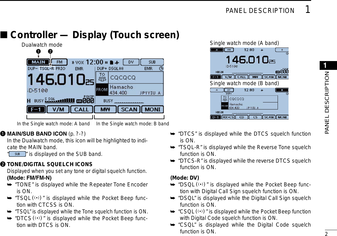
![vNew2001 New2001The following instructions and installers are included on the CD.•Basicinstructions Basic operating instructions, and are the same instructions that are in this manual•FullInstructions Full operating instructions, and more details are described than in this manual•OperatingGuide Operating guide for using the touch screen, Menu items and Quick menu items. Contains the same information that is in the supplied leaflet.•HAMradioTerms A glossary of HAM radio terms•CS-5100Instructionmanual Instructions for the CS-5100 cloning software installation and use•CS-5100Installer Installer for the CS-5100 cloning software•Adobe® Reader® Installer Installer for Adobe® Reader®ABOUT THE SUPPLIED CD DStarting the CDInsert the CD into the CD drive. q • Double click “Autorun.exe” on the CD. • Depending on the PC setting, the Menu screen shown below is automatically displayed.Click the desired button to open the file. w • To close the Menu screen, click [Quit].A PC with the following Operating System is required.• Microsoft® Windows® 8.1, Microsoft® Windows® 8, Micro-soft® Windows® 7 , Microsoft® Windows Vista® or Microsoft® Windows® XPTo read the guide or instructions, Adobe® Reader® is required. If you have not installed it, please install the Adobe® Reader® on the CD or downloaded it from Adobe Systems Incorporated’s website.Quits the menu screenInstalls the Adobe® Reader®Opens theGlossaryInstalls theCS-5100Opens the FullInstructionsOpens theOperating GuideOpens the BasicInstructions (this manual)Opens theCS-5100Instructions](https://usermanual.wiki/ICOM-orporated/348400/User-Guide-2227051-Page-6.png)
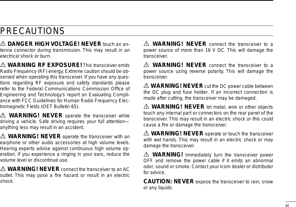
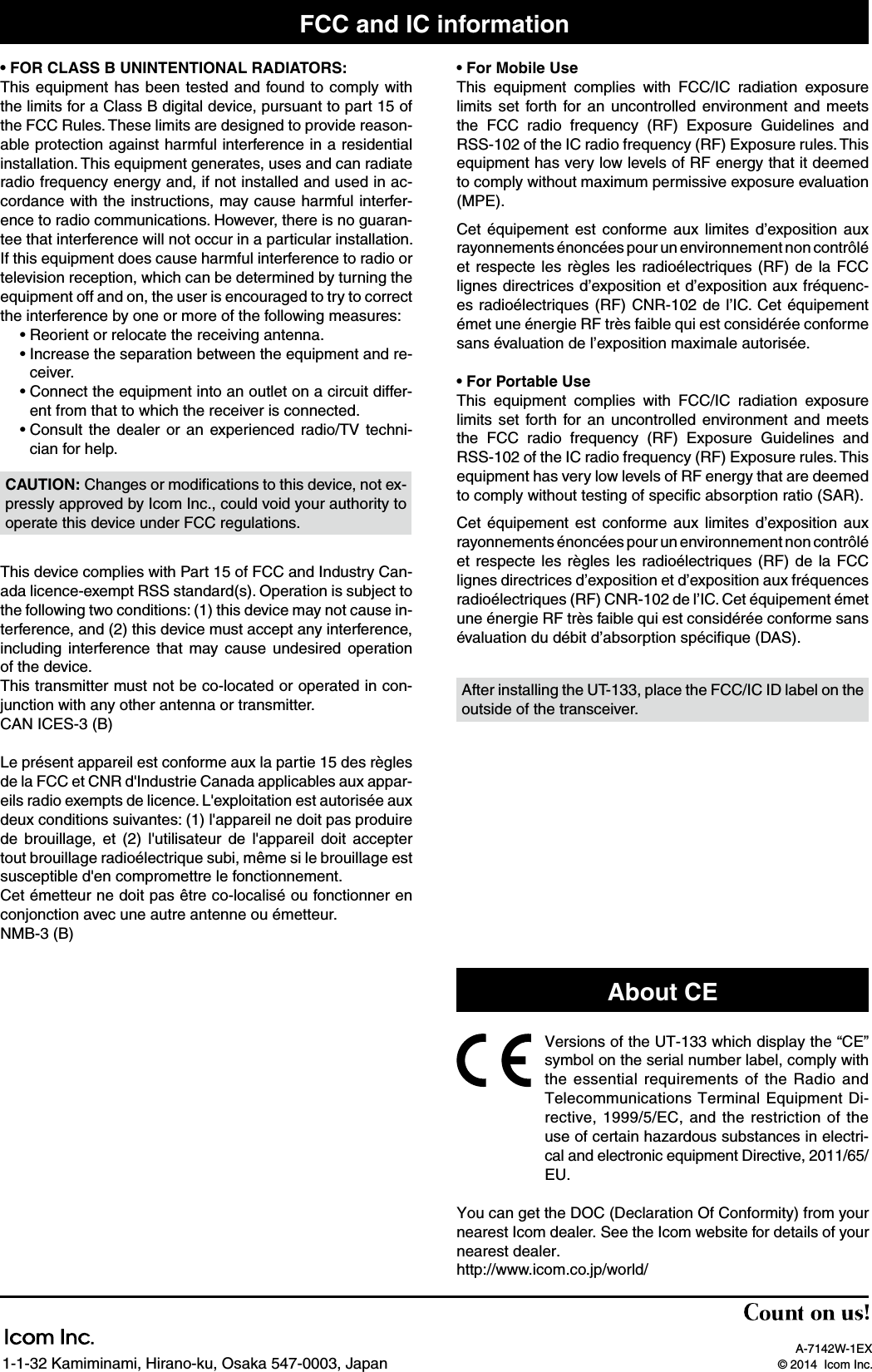
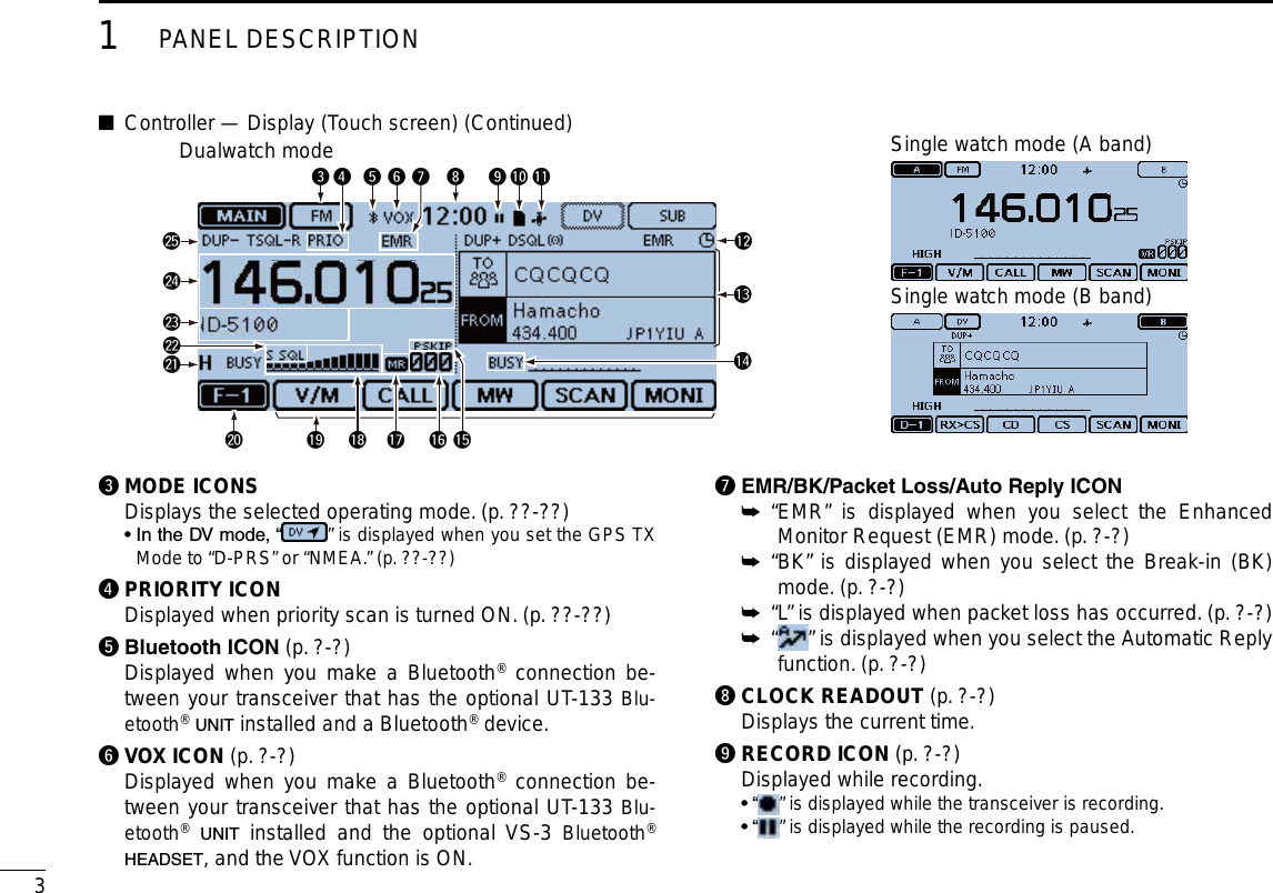
![1New2001New2001PANEL DESCRIPTION1New2001ID-5100qqwwerrey u i oDisplayq SQUELCH CONTROL [SQL] Rotate to adjust the squelch level. (p. ??-??) • Normally, set the squelch level to where noise and the “BUSY” icon just disappear. (closed) • You can use the S-Meter Squelch or Attenuator function by rotat-ing the control clockwise beyond the center position. (p. ??-??)About control’s operationIn the Dualwatch mode, the left side controls are used for the left side band, and the right side controls are used for the right side.In the Single watch mode, the left side controls are used for the A band, and the right side controls are used for the B band.Controller — Front panel ■w VOLUME CONTROL [VOL] Rotate to adjust the audio level. (p. ??-??)e MAIN UNIT CONNECTOR Connect the controller to the Main unit using the supplied control cable. (p. ??-??)r TUNING DIAL [DIAL] In the VFO mode, rotate to select the operating fre- ➥quency, and in the Memory mode, rotate to select a Memory channel. (pp. ??-??, ??-??) In the Menu screen or Quick Menu window, rotate to ➥select a desired option or value. (pp. ??-??, ??-??) While scanning, rotate to change the scanning direc- ➥tion. (p. ??-??)t POWER KEY [PWR] Hold down for 1 second to turn power ON or OFF. (p. ➥??) Push to audibly announce the operating frequency, ➥mode or a selected call sign. (p. ??-??)y [MENU] (Touch screen) (p. ??-??) Touch to open the Menu screen.u [HOME] (Touch screen) (p. ??-??) Touch to select the Home channel.i [DR] (Touch screen) (p. ??-??) Touch to open the DR screen.o [QUICK] (Touch screen) (p. ??-??) Touch to open the Quick Menu window.](https://usermanual.wiki/ICOM-orporated/348400/User-Guide-2227051-Page-14.png)
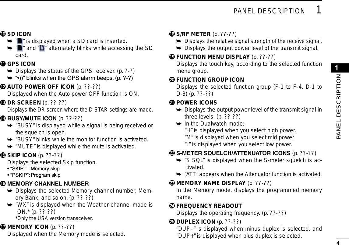
![51PANEL DESCRIPTIONNew2001 New2001Controller — Display (Touch screen) (Continued) ■Function menu DYou can toggle the function group to select the desired func-tion keys to operate the transceiver, depending on the trans-ceiver’s operating mode or status.Each function key works for the MAIN band.• In the VFO, Memory or Call channel mode, you can select the F-1 to F-4 menus.• In the DR screen, you can select the D-1 to D-3 menus. Touch the group icon to toggle the function group. ➥ Touch the group icon for 1 second to display the function ➥menu list.q w e r tq [V/M] Touch to toggle between the VFO and Memory modes.w [CALL] Touch to turn the Call channel mode ON or OFF.e [MW]Touch to open the Memory Write window. ➥ In the VFO mode or the DR screen, touch for 1 second ➥to store the operating data into the blank channel. In the Memory or Call channel mode, touch for 1 sec- ➥ond to open the Memory Edit screen.r [SCAN]Touch to open the Scan type setting window. ➥ Touch for 1 second to start the last used scan. ➥t [MONI] Touch to turn the Monitor function ON or OFF.u i o !0yy [SKIP] (Appears in the Memory mode.) Touch to open the Scan Skip setting window.u [DTMF] Touch to open the DTMF send window.i [VOICE] ( Displayed only when you insert an SD card into the trans-ceiver’s SD card slot.) Touch to open the “VOICE TX” screen.o [LOW] Touch to open the TX power setting window.!0 [GPS] Touch to open the GPS item setting window.](https://usermanual.wiki/ICOM-orporated/348400/User-Guide-2227051-Page-18.png)
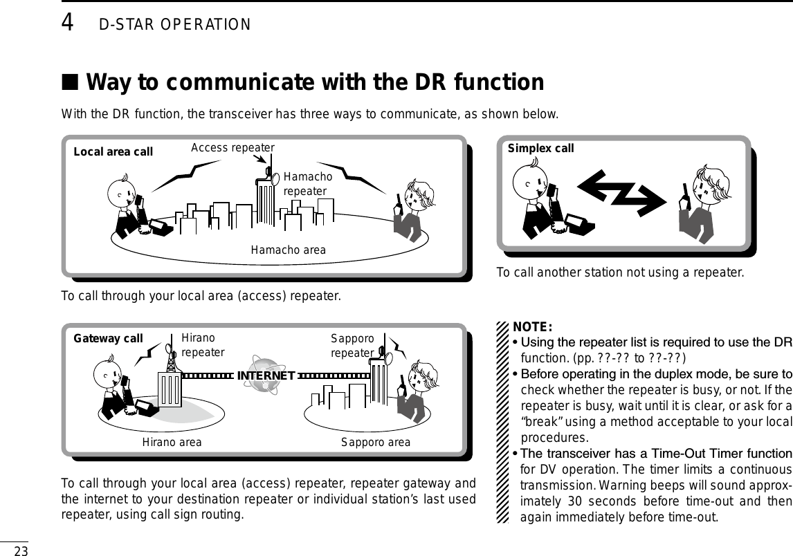
![New200161PANEL DESCRIPTION1PANEL DESCRIPTION!2 !3 !4 !5!1!1 [DUP] Touch to open the duplex direction setting window.!2 [TONE] (Displayed only when in the FM/FM-N mode.) Touch to open a Tone function setting window.!3 [REC] ( Displayed only when you insert an SD card into the trans-ceiver’s SD card slot.) Touch to start recording a QSO (communication) audio.!4 [SCOPE] Touch to open the sweep item setting window.!5 [≈] ( Displayed only when you select “Continuous Sweep” in [SCOPE](!4).) Touch to start or stop a continuous sweeping.!7 !8!6(Displayed only when in the DV mode.)!6 [RX>CS]Touch to open the “RX>CS” screen. ➥ Touch for 1 second to set the received station call sign ➥as the destination (UR) call sign.!7 [CD] Touch to open the “RX HISTORY” screen.!8 [CS] Touch to open the “CALL SIGN” screen.!7 !8 !9 @0!6!9 [SCAN] Touch to open the DR scan setting window. ➥ Touch for 1 second to start the last used scan. ➥@0 [MONI] Touch to turn the Digital Monitor function ON or OFF.u i o !0@1@1 [SKIP] Touch to open the skip setting window for the Access ➥repeater scan. Touch for 1 second to set the skip setting in the Func- ➥tion menu.@2 !3e@2 [DSQL] (Appears in the DV mode.) Touch to open the Digital squelch function setting window. If you set the operating mode to “DV” in the VFO mode, [DSQL] is displayed instead of [TONE] on the F-3 menu.](https://usermanual.wiki/ICOM-orporated/348400/User-Guide-2227051-Page-19.png)
![71PANEL DESCRIPTIONNew2001 New2001q w e r t y u ioMain unit — Front and rear panels ■q SD CARD SLOT [SD CARD] Insert an SD card (purchase separately). (p. ??-??)w CONTROLLER CONNECTOR [CONTROLLER] Connects to the Controller using the supplied control cable.e MICROPHONE CONNECTOR [MIC] Plug in the supplied microphone (HM-207) or the optional microphone (HM-154).r ANTENNA CONNECTOR Connect a 50 ø impedance of antenna with a PL-259 con-nector. The transceiver has a built-in duplexer, so you can use a 144 and 430 MHz dual-band antenna without needing an external duplexer. t COOLING FAN The cooling fan for heat dissipation. You can select the Fan control option in the Menu screen, and automatically starts to rotate when you begin transmit-ting, or continuously rotates from power ON.y DATA JACK [DATA] Connect a PC through the optional OPC-2218LU DATA COMMUNICATION CABLE, for cloning or low-speed data com-munication in the DV mode. (p. ??-??)uEXTERNALSPEAKERJACK1[SP1]i EXTERNAL SPEAKER JACK 2 [SP2] Connect to an 8 ohm external speaker. • When you connect external speakers to [SP1] and [SP2], the A band (left side display) audio is heard from [SP1] and the B band (right side display) audio is heard from [SP2]. • When you connect an external speaker to [SP1], the A and B band audio is heard from [SP1]. In this case, the internal speaker is disabled. • When you connect an external speaker to [SP2], the A band (left side display) audio is heard from the inter-nal speaker and the B band (right side display) audio is heard from the external speaker.](https://usermanual.wiki/ICOM-orporated/348400/User-Guide-2227051-Page-20.png)
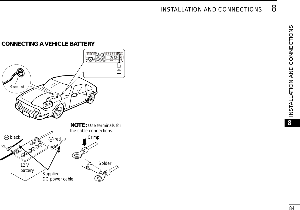
 Connect 13.8 V DC power source through the supplied DC power cable.Microphone connector information D12345678Front panel viewPINNo.NAME DESCRIPTION SPECIFICATIONS18 V +8 V DC output. Maximum 10 mA2 MIC U/D Frequency Up/Down UP: GroundDN: Ground through 470 ˘3M8V SW HM-207 connectionGrounds when the HM-207 is connected. —4 PTT PTT input Ground for trans-mission5 MIC E Microphone ground —6 MIC Microphone input —7 GND PTT ground —8DATA INWhen the HM-207 is connected, inputs HM-207 data—Microphone(HM-207) ■With the HM-207, you can input numbers for frequency or Memory channel setting, and easily adjust the audio volume or squelch level.qwe!0tyiuor!7Mic element!6!1!2!3!4!5qLED1 Lights red while transmitting with [PTT].w [∫]/[√] (UP/DOWN) KEYS Push to change the operating frequency or Memory ➥channel. Hold down to continuously change the frequency or ➥Memory channel.](https://usermanual.wiki/ICOM-orporated/348400/User-Guide-2227051-Page-21.png)
![91PANEL DESCRIPTIONNew2001 New2001Microphone (HM-207) (Continued) ■e [PTT] SWITCH Hold down to transmit, release to receive.r [VFO/MR•] KEY Push to toggle between the VFO and Memory modes. ➥(p. ?-?) Hold down for 1 second to turn the Lock function ON ➥or OFF. (p. ?-?)t [HOME/CALL] KEYPush to select the Home channel. ➥ Hold down for 1 second to turn the Call channel mode ➥ON or OFF.y [MAIN/DUAL] KEY In the Single watch mode, push to toggle between the ➥A and B bands. In the Dualwatch mode, push to toggle between the ➥MAIN and SUB bands. Hold down for 1 second to toggle between the Dual- ➥watch and Single watch modes.u[F-1]KEY Push to activate the preprogrammed function of the [F-1] key. (Default: During RX/Standby: [BAND/BANK] During TX: [T-CALL]) [F-2]KEY Push to activate the preprogrammed function of the [F-2] key. (Default: During RX/Standby: [Monitor] During TX: [---])You can assign a desired function in the Menu screen.i [CLR] KEY In the Menu screen or Quick Menu window, push to return to the standby screen.p [ENT] KEY In the VFO mode, push to open the frequency entry ➥window. In the Memory mode, push to open the memory chan- ➥nel number input window.After the numeral input, push to set. ➥qwe!0tyiuor!7Mic element!6!1!2!3!4!5](https://usermanual.wiki/ICOM-orporated/348400/User-Guide-2227051-Page-22.png)
![New2001101PANEL DESCRIPTION1PANEL DESCRIPTION!0 LED 2 Lights green when transceiver’s power is ON.!1 [VOL∫/A] KEYPush to increase the audio output level. ➥When entering a DTMF code, push to input ‘A.’ ➥!2 [VOL√/B]KEYPush to decrease the audio output level. ➥When entering a DTMF code, push to input ‘B.’ ➥!3 [SQL∫/C] KEYPush to increase the squelch level. ➥When entering a DTMF code, push to input ‘C.’ ➥!4 [SQL√/D] KEYPush to decrease the squelch level. ➥When entering a DTMF code, push to input ‘D.’ ➥!5 [#/CE] KEY In the frequency entry screen, push to delete a num- ➥ber.When entering a DTMF code, push to input ‘#.’ ➥!6 [M/.] KEY In the frequency entry screen, push to input a ‘.’ (deci- ➥mal point).When entering a DTMF code, push to input ‘ ➥M.’!7[0]to[9]KEYS In the frequency entry window or while entering a DTMF code, push to input ‘0’ through ‘9.’Setting frequency and Memory channel D[Example for frequency setting]First, push [VFO/MR• ] to select the VFO mode.Toenterthe435.680MHzfrequency:Push [4], [3], [5], [6], [8], [0], then [ENT]. ➥Tochangethe439.680MHzto439.540MHz:Push [•], [5], [4], [0], then [ENT]. ➥Toenterthe433.000MHzfrequency:Push [4], [3], [3], then [ENT]. ➥[Example for Memory channel setting]First, push [VFO/MR• ] to select the Memory mode.To select the Memory channel ‘5’:Push [5] then [ENT]. ➥](https://usermanual.wiki/ICOM-orporated/348400/User-Guide-2227051-Page-23.png)
![New2001New200111New2001BASICOPERATION2Power ON the power ■Hold down [ ➥] for 1 second to turn ON the power. • A beep sounds and, after “ICOM ID-5100” and power source voltage are displayed, the operating frequency appears. • Hold down [ ] for 1 second to turn OFF the power.[ ] Setting audio volume and ■squelch levelRotate [VOL] to adjust the audio level. q Rotate [SQL] until the noise and the “BUSY” icon just dis- wappear. • Rotating [SQL] counterclockwise makes the squelch tight. The tight squelch is for strong signals. • When rotating [SQL] clockwise beyond the center position, [SQL] can be used as ‘S-meter Squelch’ or ‘Attenuator.’ Select the [SQL] option in the Menu screen. (p. ??-??)[VOL][SQL][VOL][SQL]Selecting a tuning step ■Rotating [DIAL] changes the frequency in the selected tuning steps.The VFO scan uses this step to search for a signal.Tuning steps (kHz)5 6.25 8.33* 10 12.5 1520 25 30 50 Auto**Appears only when the AIR band is selected.Tuning step selection DTouch the kHz digits for 1 second. q • Opens the Tuning step setting window. Touch the desired tuning step. w • Sets the tuning step, and then returns to the previous screen. • You can set the tuning step for both the VFO and Memory mode. • You can set the tuning step for each band. • In the Tuning step setting window, rotating [DIAL] also selects the tuning step.](https://usermanual.wiki/ICOM-orporated/348400/User-Guide-2227051-Page-24.png)
![New2001122BASIC OPERATIONNew20012BASIC OPERATIONSelecting the watch mode ■The transceiver has two independent watch modes: Dual-watch mode and Single watch mode.Dualwatch modeThe Dualwatch mode uses the MAIN and SUB bands, and you can simultaneously monitor both bands. In the Dualwatch mode, both MAIN and SUB bands are dis-played side by side.Touching [MAIN] or [SUB] for 1 second selects the Single watch mode.Single watch modeThe Single watch mode uses the A and B bands, instead of the MAIN and SUB bands, and you can monitor one of them at a time.In the Single watch mode, only one of the A or B bands is displayed. Touching [A] or [B] for 1 second selects the Dualwatch mode.NOTE: The Dualwatch left side band becomes the A band in the Single watch mode.The Dualwatch right side band becomes the B band in the Single watch mode.SelectingtheMAINorSUBband D Touch [SUB] to toggle the displayed band between the ➥MAIN band and the SUB band. • [MAIN] will be highlighted to indicate the MAIN band.In Single watch mode: A bandA bandIn Single watch mode:BbandDualwatch modeSingle watch modeMAIN band SUBbandMAIN bandSUBband](https://usermanual.wiki/ICOM-orporated/348400/User-Guide-2227051-Page-25.png)
![132BASIC OPERATIONNew2001 New2001Selecting the operating band ■The transceiver can receive the AIR, 144 MHz or 430 MHz bands.The frequency range on each operating band is shown to the right.You can transmit on only the 144 MHz and 430 MHz bands.Operating band Frequency rangeAIR 108.000 MHz to 137.000 MHz144 MHz 137.000 MHz to 174.000 MHz430 MHz 380.000 MHz to 479.000 MHzOperating band setting DTouch the Memory channel number. q • Opens the Mode setting window. Touch [VFO]. w • Selects the VFO mode. Touch the MHz digits. e • Opens the operating band setting window. Touch the desired operating band. r • The operating band setting window disappears. • Touch [F-INP] to open the frequency entry window. You can directly enter a frequency.](https://usermanual.wiki/ICOM-orporated/348400/User-Guide-2227051-Page-26.png)
![New2001142BASIC OPERATION2BASIC OPERATIONDirect frequency input ■You can directly enter a frequency in the frequency entry win-dow.Touch the Memory channel number. q • Opens the Mode setting window. Touch [VFO]. w • Selects the VFO mode.Touch the MHz digits. e • Opens the operating band setting window. Touch [F-INP]. r • Opens the frequency entry window. Touch the numbers to enter the desired frequency. t • The rst entered digit is displayed to the left. Then the next entered digit is displayed to the right of the previously entered digit. • If desired, touch “CE” to delete the entry. Touch [ENT] to set the frequency. y • Closes the frequency entry window. • If you touch [ENT] without entering a digit below 100 kHz, all unentered digits are set to “0.” The entered frequency is displayed.](https://usermanual.wiki/ICOM-orporated/348400/User-Guide-2227051-Page-27.png)
![152BASIC OPERATIONNew2001 New2001Selecting the Mode and the DR function ■VFO/Memory/Call channel/Weather channel* mode DVFO modeThe VFO mode is used to set the operating frequency.Memory modeThe Memory mode is used to operate on Memory channels.Call channel modeThe Call channel mode is used to operate on the most-often used frequencies.Weather channel mode*The Weather channel mode is used to monitor weather chan-nels from the NOAA (National Oceanographic and Atmo-spheric Administration) broadcasts.*Selectable in only the U.S.A. version transceivers.Touch the Memory channel number. q • Opens the Mode setting window. Select the desired Mode. w Rotate [DIAL] to select the operating frequency or a channel. e • “ ” and the selected Memory channel number are displayed. • A selected Call channel number (“144 C0,” “144 C1,” “430 C0” or “430 C1”) is displayed. • The selected weather channel number (“WX-01” to “WX-10”) is displayed. Call channel modeVFO modeMemorymodeWeather channel mode*](https://usermanual.wiki/ICOM-orporated/348400/User-Guide-2227051-Page-28.png)
![New2001162BASIC OPERATION2BASIC OPERATIONDR(D-STARRepeater)functionselection DThe DR (D-STAR Repeater) function is for D-STAR repeater operation. In this mode, you can easily select the prepro-grammed repeaters and UR call signs by rotating [DIAL].See page ??-?? for the DR function details.Touch [DR]. q • Displays the DR screen. [DR] Rotate [DIAL] to select a desired access repeater. w DR screenTouch [DR]. e • Closes the DR screen.Transmitting ■Transmitting on an Amateur band DBefore transmitting, monitor the operating frequencyto make sure transmitting won’t cause interference to other stations on the same frequency.CAUTION: Transmitting without an antenna may damage the transceiver.You can transmit on only the 144 MHz and 430 MHz bands.Set the operating frequency. (p. ?-?) qTouch the Power icon. w • Opens the output power level setting window.Touch the transmit output power level. e • Select a level to suit your operating requirements. • In the Dualwatch mode, “H” indicates high power, “M” in-dicates mid power and “L” indicates low power. Hold down [PTT] to transmit, and speak at your normal rvoice level. • The transmit LED lights red while transmitting. • The S/RF meter displays the output power level.Release [PTT] to receive. t](https://usermanual.wiki/ICOM-orporated/348400/User-Guide-2227051-Page-29.png)
![172BASIC OPERATIONNew2001 New2001Selecting the operating mode ■Operating modes are determined by the modulation of the radio signals. The transceiver has a total of five operating modes, AM, AM-N, FM, FM-N and DV.The FM mode is set as a default.Touch the Mode icon. q • Opens the operating mode setting window. Touch a desired operating mode. w • You can select the AM or AM-N mode for only the AIR band (108.000 MHz to 136.995 MHz). • You can select the FM, FM-N or DV mode for only the 144 and 430 MHz bands. • While in the FM-N mode, the TX modulation is automatically set to narrow (approximately ±2.5 kHz) • While in the DV mode, [GPS] appears in the operating mode setting window, and you can select the GPS TX mode. When the GPS TX mode is set, “ ” is displayed. (p. 8-??)Lock function ■You can use the Lock function to prevent accidental frequen-cy changes and unnecessary function access.Touch [QUICK]. q [QUICK]Touch “<<Lock>>”. w • If the item is not displayed, touch [∫] or [√] one or more times to select another page. • When the Lock function is turned ON and the locked key is pushed, the touch screen is touched, or [DIAL] is rotated, the “LOCK” dialog box appears. • To turn OFF the Lock function, touch [OFF] in the “LOCK” dialog box. • You can still use [ ], [PTT], [SQL] and [VOL] while the Lock func-tion is ON. Quick Menu window](https://usermanual.wiki/ICOM-orporated/348400/User-Guide-2227051-Page-30.png)
![New2001182BASIC OPERATION2BASIC OPERATIONHome channel function ■Home channels are often-used frequencies you can preset in the transceiver’s VFO mode, Memory mode and DR function. Select the Home channel function by just touching [HOME] in each mode.Home channel setting D Select the desired mode or the DR screen to set the Home qchannel.Select a frequency to be set as the Home channel. w • While in the DR screen, select “FROM.”Touch [HOME] for 1 second. eTouch the displayed item to set the Home channel. r • While in the VFO mode, touch “Set Frequency,” while in the Memory mode, touch “Set Channel.” or while in the DR screen, touch “Set Repeater.” Speech function ■When you push [ ](SPEECH), the Speech function audibly announces the displayed frequency and operating mode in the VFO, Memory or Call channel modes, or the call sign of the DR function.Also, you can use other speech functions, such as the [DIAL] speech function and Mode speech function. (pp. ??-??, ??-??)NOTE: When you push [ ](SPEECH) while recording the received audio in the DV mode, the received audio will be muted, and no audio is recorded onto the SD card.In modes other than the DV mode, the received audio will be recorded.You set the detail settings of the Speech function in the “SPEECH” item of the Menu screen. (p. ?? to ??)Example: When pushing [ ](SPEECH).[ ](SPEECH)JP1YIU A](https://usermanual.wiki/ICOM-orporated/348400/User-Guide-2227051-Page-31.png)
![New200119New2001New2001MEMORY MANAGEMENT3Writing a Memory channel ■The Memory mode is useful to quickly select often-used re-peaters.In this section, the basic channel programming is described.See the Full Instructions for details.Example: Writing 146.030 MHz/FM mode into a blank chan-nel.Touch the Function group icon one or more times. q • Selects the F-1 menu.Touch [MW] for 1 second. w • The memory contents are briey displayed, and then the operat-ing data are saved into a blank channel. Stored data Checking the programmed ■Memory contentsThe programmed Memory channels can be checked on the “MEMORY LIST” screen.Example: Checking the contents of the Memory channel ‘5.’Touch [MENU]. q Touch “Memory CH.” w (Manage Memory > Memory CH) • If the item is not displayed, touch [∫] or [√] one or more times to select the page. Touch “ALL.” e • Displays the “MEMORY CH ALL” screen.](https://usermanual.wiki/ICOM-orporated/348400/User-Guide-2227051-Page-32.png)
![203MEMORY OPERATIONNew20013MEMORY OPERATIONNew2001Touch [ r∫] or [√]. • Displays Channel 5. Touch “005.” t • Displays the programmed data in Channel 5. • Touch [∫] or [√] one or more times to select the page. Touch [MENU]. y • Closes the “MEMORY CH ALL” screen.](https://usermanual.wiki/ICOM-orporated/348400/User-Guide-2227051-Page-33.png)
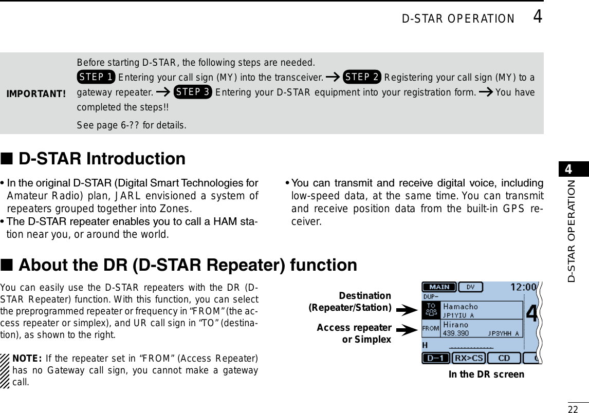
![New200121New2001New2001D-STAROPERATION4UniquefeaturesofD-STAR ■ Easy Cross band operation ● Easy call sign entry with the Re- ●peater list or TX/RX History Call Sign Capture key ●[RX>CS] makes call sign capture easy.1200 MHz 430 MHzYou can communicate with a 1200 MHz D-STAR station using the ID-5100!Easy Destination (To) setting!This key makes call sign capture easy!](https://usermanual.wiki/ICOM-orporated/348400/User-Guide-2227051-Page-34.png)
![New2001244D-STAR OPERATION4D-STAR OPERATIONYou can enter up to six MY call signs, in [MY1] through [MY6].Example: Enter “JA3YUA” as your own call sign into the MY call sign memory [MY1].Displays the MY Call Sign edit screen1.Touch [MENU]. qTouch [My Call Sign]. w (My Station > My Call Sign) • If the item is not displayed, touch [∫] or [√] one or more times to select the page. Touch the MY call sign memory channel “1” ([MY1]) for 1 esecond. Touch “Edit.” r • Opens the “MY CALL SIGN (MYM)” edit screen. The channel number selected in step e is displayed on ‘M.’ • A cursor appears and blinks. Enter the call sign2. Touch the desired keypad to select the first digit. t (Example: J). • A to Z, 0 to 9, / and (Space) are selectable. • Touch “ab⇔12” to toggle between the Alphabet input and Num-ber input modes. • Touch [CLR] to delete the selected character, symbol or num-ber. • Touch “SPACE” to input a space. Touch [ y] to move the cursor backwards, or touch [] to move the cursor forwards. Repeat steps u t and y to enter your call sign of up to 8 characters, including spaces. (Example: First J, then A, then 3, then Y, then U, then A) To enter ‘3.’NOTE: Your call sign must match the call sign you regis-tered. (p. ??-??)Enter your call sign into the transceiver ■](https://usermanual.wiki/ICOM-orporated/348400/User-Guide-2227051-Page-37.png)
![254D-STAR OPERATIONNew2001 New2001Enter your call sign into the transceiver (Continued) ■Save the call sign3. Touch [ENT]. i • Saves the entered call sign and returns to the “MY CALL SIGN” screen. • See “Convenient” below if you want to enter a note. Touch the entered call sign. o • Sets the call sign to be used as MY call sign. !0 Touch [MENU]. • Closes the “MY CALL SIGN” screen.Moves the cursorDeletesSetsCancelsEnters a spaceToggles the entry modeKeys used for entry](https://usermanual.wiki/ICOM-orporated/348400/User-Guide-2227051-Page-38.png)
![New2001264D-STAR OPERATION4D-STAR OPERATIONConvenient! ✓If desired, enter a note of up to 4 characters, such as the model of the transceiver, name, area name, and so on, after your call sign. Touch [ q] one or more times until the cursor moves to the right of the “/”. Repeat steps w t and y on the page ??-?? to enter a 4 character note. (Example: 5100)](https://usermanual.wiki/ICOM-orporated/348400/User-Guide-2227051-Page-39.png)
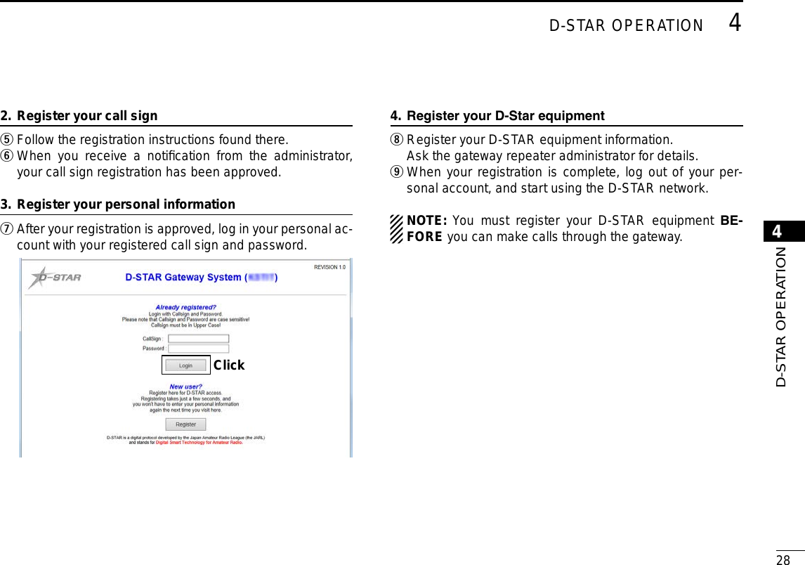
![274D-STAR OPERATIONNew2001 New2001Register your call sign at a gateway repeater ■Ifneeded, ask thegateway repeater administrator forcall sign registration instructions.To use the Internet, you must register your call sign with a repeater that has a gateway, usually one near your home lo-cation.About the registration process described:This section describes the call sign registration process at a repeater that is connected to the US Trust server. There are other systems as well, and they have their own registration process. For information on how to register on one of them, contact the administrator of a repeater that uses the alternate system.Access the call sign registration screen1. Access the following URL to find the gateway repeater qclosest to you. http://www.dstarusers.org/repeaters.php Click the call sign of the repeater that you want to register wto. Click the “Gateway Registration URL:” link address. e The “D-STAR Gateway System” screen appears. r Click [Register] to start the New User registration.Click](https://usermanual.wiki/ICOM-orporated/348400/User-Guide-2227051-Page-40.png)
![294D-STAR OPERATIONNew2001 New2001Making a Simplex call ■You can make a transceiver to transceiver call (through no repeater) in the DR screen.NOTE: Depending on the transceiver's version, the fre-quencies may be different. Check for acceptable frequen-cies for your operating area. ✓What is a Simplex Call??A simplex call is a direct call to another station, not using a repeater.Example: Making a simplex call on 433.450 MHz.“FROM” (Simplex channel) setting1.Touch [DR]. qCheck whether or not “FROM” is selected. w • If “FROM” is not selected, touch the “FROM” eld.Touch the “FROM” field. e • Opens the “FROM SELECT” screen. “FROM” is selected.Touch “Repeater List.” r • Opens the “REPEATER GROUP” screen. Touch “Simplex.” t Touch a desired frequency. (Example: 433.450) y • Returns to the DR screen, and the selected frequency is dis-played in “FROM.” • “CQCQCQ” is displayed in “TO.” - If a station call sign is set in “TO,” select “Local CQ” in the “TO SELECT” screen to set “CQCQCQ” in “TO.”](https://usermanual.wiki/ICOM-orporated/348400/User-Guide-2227051-Page-42.png)
![New2001304D-STAR OPERATION4D-STAR OPERATIONHold down [PTT] to transmit2. • The LED1 on the microphone lights red. When you make a simplex call in the VFO mode, the LCD changes, as shown below.While transmitting in the DV modeFor your reference:The simplex frequencies can be changed in the MENU screen.( DV memory > Repeater List > Repeater group > Simplex)](https://usermanual.wiki/ICOM-orporated/348400/User-Guide-2227051-Page-43.png)
![314D-STAR OPERATIONNew2001 New2001Accessing repeaters ■This section describes how to check whether or not you can access your local area repeater (Access repeater), and if your signal is successfully sent to a destination repeater.If your call sign (MY) has not been set, or your call sign and equipment have not been registered at a D-STAR re-peater, see page ??.Select your Access repeater (“FROM”)1.Touch [DR]. qCheck whether or not “FROM” is selected. w • If “FROM” is not selected, touch the “FROM” eld.Touch the “FROM” field. e • Opens the “FROM SELECT” screen. Touch “Repeater List.” r • Opens the “REPEATER GROUP” screen. Touch the repeater group where your access repeater is tlisted. (Example: “11: Japan”) Touch your access repeater. (Example: “Hirano”) y • Returns to the DR screen, and the selected repeater name is displayed in “FROM.” Even if you select just the repeater name, the repeater call sign, its frequency, duplex setting, frequency offset and Gateway call sign are automatically set.](https://usermanual.wiki/ICOM-orporated/348400/User-Guide-2227051-Page-44.png)
![New2001324D-STAR OPERATION4D-STAR OPERATIONSelect the Destination repeater (“TO”)2. Touch the “TO” field. u • Check whether “TO” is selected.Touch the “TO” field again. i • Opens the “TO SELECT” screen. Touch “Gateway CQ.” o • Opens the “REPEATER GROUP” screen.!0 Touch the repeater group where your destination repeater is listed. (Example: “11: Japan”)!1 Touch your destination repeater. (Example: “Hamacho”) • Returns to the DR screen, and the selected repeater name is displayed in “TO.” Check whether you can access the repeater3. !2 Hold down [PTT] for approximately 1 second to access the repeater. !3 If you get a reply call, or “UR?” appears on the LCD within 3 seconds, your signal reached your access repeater and your call was successfully sent from your destination re-peater.Successfully sent!NOTE: See page ??-?? for status indications after a re-peater system reply is received.](https://usermanual.wiki/ICOM-orporated/348400/User-Guide-2227051-Page-45.png)
![334D-STAR OPERATIONNew2001 New2001Using the RX history ■When a DV call is received, the call signs of the caller, the called station and the called station’s access repeater are stored in the RX history file.Up to 50 calls can be stored.This section describes how to view the RX history screen and how to save the call sign to memory.The S-meter appears and the caller’s call sign is displayed.Whenreceivingacallfrom“JM1ZLK.”To display a received call sign1. Touch the Function group icon one or more times. q • Selects the D-1 menu.Touch [CD]. w • Opens the “RX HISTORY” screen. • Touch [∫] or [√] one or more times to select other RX history memories. • The rst page of the “RX HISTORY” screen displays the latest RX record of the MAIN band. The second page or later displays the record according to the received date and time, regardless of the band it was received on.RX HISTORY record numberRX messageRX HISTORY screen(LAST (MAIN))Received date and timeCaller station( A note may be displayed after “/”.)Repeater call sign of the called stationCalled station( “CQCQCQ” is displayed if you received a Local CQ or a Gateway CQ callDisplays the detail screenCurrent timeFirst page](https://usermanual.wiki/ICOM-orporated/348400/User-Guide-2227051-Page-46.png)
![New2001344D-STAR OPERATION4D-STAR OPERATION Save the destination call sign into your call sign mem-2. ory from RX History Touch [ e∫] or [√] one or more times to select the RX HIS-TORY record with the call sign that you want to save to memory.Touch [DETAIL]. r Touch [QUICK]. tTouch “Add To Your Memory.” y Touch the call sign that you want to save. u (Example: “JM1ZLK”) The display opens the “YOUR CALL SIGN EDIT” screen, and the call sign is automatically set.Touch “NAME.” i • Opens the “NAME” screen. • Enter a name of up to 16 characters, including spaces. (Example: TOM) Touch [ENT]. o • Returns to the “YOUR CALL SIGN EDIT” screen.!0 Touch “<<Add Write>>.” • Opens the “Add write?” window. !1 Touch [YES]. • Returns to the “RX HISTORY” screen.](https://usermanual.wiki/ICOM-orporated/348400/User-Guide-2227051-Page-47.png)
![354D-STAR OPERATIONNew2001 New2001Capturing a call sign ■After you receive a repeater’s signal, the calling sta-tion’s call sign can be captured by touching the Call Sign Capture key ([RX>CS]) for 1 second. Then you can quickly and easily reply to the call.What is the Call Sign Capture key?? ✓Touching the Call Sign Capture key for 1 second sets the last received station call sign as a temporary destination, and makes replying quick and easy.While receivingWhen receiv-ing a call from “JG3LUK.”Call Sign Capture keySet the received call sign to the destination1. Touch the Function group icon one or more times. q • Selects the D-1 menu. D-1 menuTouch [RX>CS] for 1 second. w • Beep sounds when touched. • After 1 second, two beeps sound, and the station call sign is an-nounced.Blinks after selecting a call sign.When you touch[RX>CS].BeepsJG3LUKAfter1secondBeeps](https://usermanual.wiki/ICOM-orporated/348400/User-Guide-2227051-Page-48.png)
![New2001364D-STAR OPERATION4D-STAR OPERATIONNOTE:• After touching [RX>CS], you can select another call sign in the RX history.• When a received signal is weak, DR scanning or the pow-er save is ON, the call sign may not be received correctly. In that case, “--------” appears, an error beep sounds, and a quick reply call cannot be made.Hold down [PTT] to transmit2. • The LED1 on the microphone lights red. Touch [RX>CS]. e • Returns to the previous call sign setting. Returns to the previous screen](https://usermanual.wiki/ICOM-orporated/348400/User-Guide-2227051-Page-49.png)
![374D-STAR OPERATIONNew2001 New2001Making a Local area call ■A Local area call can be made when “Local CQ” is used to set “CQCQCQ” in “TO” (Destination). ✓What is a Local Area Call??To call through your local area (access) repeater.Set “FROM” (Access repeater)1.Touch [DR]. qCheck whether or not “FROM” is selected. w • If “FROM” is not selected, touch the “FROM” eld.Touch the “FROM” field. e • Opens the “FROM SELECT” screen. Touch “Repeater List.” r • Opens the “REPEATER GROUP” screen. Touch the repeater group where your access repeater is tlisted. (Example: “11: Japan”) Touch your access repeater. (Example: “Hirano”) y • Returns to the DR screen, and the selected repeater name is displayed in “FROM.”](https://usermanual.wiki/ICOM-orporated/348400/User-Guide-2227051-Page-50.png)
![New2001384D-STAR OPERATION4D-STAR OPERATIONSet “TO” (Destination)2. Touch the “TO” field. u • Check whether “TO” is selected.Touch the “TO” field again. i • Opens the “TO SELECT” screen. Touch “Local CQ.” o • Returns to the DR screen, and “CQCQCQ” is displayed in “TO.” Hold down [PTT] to transmit3. • The LED1 on the microphone lights red. For your reference:The Local CQ call is used to call anyone, but you can call a specific station by simply saying their call sign.](https://usermanual.wiki/ICOM-orporated/348400/User-Guide-2227051-Page-51.png)
![394D-STAR OPERATIONNew2001 New2001Making a Gateway Repeater call ■A Gateway call can be made when a destination repeater is selected in “TO” (Destination).What is a Gateway Repeater Call?? ✓To call through your local area (access) repeater, repeater gateway, and the Internet to your desired destination repeat-er.Set “FROM” (Access repeater)1.Touch [DR]. qCheck whether or not “FROM” is selected. w • If “FROM” is not selected, touch the “FROM” eld.Touch the “FROM” field. e • Opens the “FROM SELECT” screen. Touch “Repeater List.” r • Opens the “REPEATER GROUP” screen. Touch the repeater group where your access repeater is tlisted. (Example: “11: Japan”) Touch your access repeater. (Example: “Hirano”) y • Returns to the DR screen, and the selected repeater name is displayed in “FROM.”](https://usermanual.wiki/ICOM-orporated/348400/User-Guide-2227051-Page-52.png)
![New2001404D-STAR OPERATION4D-STAR OPERATIONSet “TO” (Destination)2. Touch the “TO” field. u • Check whether “TO” is selected.Touch the “TO” field again. i • Opens the “TO SELECT” screen. Touch “Gateway CQ.” o • Opens the “REPEATER GROUP” screen. !0 Touch the repeater group where your desired destination repeater is listed. (Example: “11: Japan”) !1 Touch your destination repeater. (Example: “Hamacho”) • Returns to the DR screen, and the selected repeater name is displayed in “TO.” Hold down [PTT] to transmit3. • The LED1 on the microphone lights red. For your reference:The Gateway CQ call is used to call any repeater, but you can call a specific station by simply saying their call sign.](https://usermanual.wiki/ICOM-orporated/348400/User-Guide-2227051-Page-53.png)
![414D-STAR OPERATIONNew2001 New2001Calling an individual station ■You can make a call to an individual station when the station call sign is selected in “TO” (Destination).When you call an individual station call sign through a gate-way, your call is automatically sent to the last repeater that the station accessed. So, even if you don’t know where the station is, you can make a call using call sign routing.Set “FROM” (Access repeater)1.Touch [DR]. qCheck whether or not “FROM” is selected. w • If “FROM” is not selected, touch the “FROM” eld.Touch the “FROM” field. e • Opens the “FROM SELECT” screen. Touch “Repeater List.” r • Opens the “REPEATER GROUP” screen. Touch the repeater group where your access repeater is tlisted. (Example: “11: Japan”) Touch your access repeater. (Example: “Hirano”) y • Returns to the DR screen, and the selected repeater name is displayed in “FROM.”](https://usermanual.wiki/ICOM-orporated/348400/User-Guide-2227051-Page-54.png)
![New2001424D-STAR OPERATION4D-STAR OPERATIONSet “TO” (Destination)2. Touch the “TO” field. u • Check whether “TO” is selected.Touch the “TO” field again. i • Opens the “TO SELECT” screen. Touch “Your Call Sign.” o • Opens the “YOUR CALL SIGN” screen. !0 Touch the destination station. (Example: “TOM”) • Returns to the DR screen, and the selected station name is dis-played in “TO.” Hold down [PTT] to transmit3. • The LED1 on the microphone lights red.](https://usermanual.wiki/ICOM-orporated/348400/User-Guide-2227051-Page-55.png)
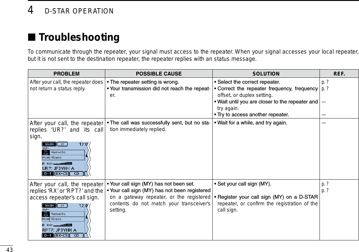
![New2001444D-STAR OPERATION4D-STAR OPERATIONPROBLEM POSSIBLECAUSE SOLUTION REF.After your call, the repeater re-plies ‘RPT?’ and call sign of the destination repeater.• The repeater cannot connect to the destina-tion repeater.• The repeater is busy.• Check the repeater setting.• Wait for a while, and try it again.p. ?—After your call, the access re-peater replies ‘RPT?’ and its call sign.• The call sign of the destination repeater is wrong. • Correctly set the destination repeater call sign.p. ?Even holding down [DR], the DR screen will not appear.• There is no repeater list in your radio. • Reload the repeater list using the SD card.• Enter the Repeater list data directly into the transceiver.p. ?Section 7 of the Full InstructionEven holding down [RX>CS], the received call sign will not set to the destination call sign.• The call sign has not been correctly re-ceived. • When a received signal is weak, or a signal is received during scanning, the call sign may not be received correctly. In that case, “--------” appears and error beeps sound, and a reply call cannot be made.• Try it again, after the transceiver has cor-rectly received the call sign. —A Local area call can be made, but the Gateway call or destina-tion station call cannot be made.• MY call sign has not been registered at a D-STAR repeater. • Register your call sign (MY) on a D-STAR repeater, or confirm the registration of the call sign.p. ?“L” appears on the LCD, and the received audio is interrupted.• While receiving through the internet, some packets may be lost due to a network error (poor data throughput performance). • Wait a while, and try it again.When the transceiver receives corrupted data, and misidentifies it is as packet loss, “L” is displayed, even if it is a Local area call.—“DV” and “FM” icons alternately blink. • While in the DV mode, an FM signal is re-ceived. • Wait a while, and try it again.p. ?](https://usermanual.wiki/ICOM-orporated/348400/User-Guide-2227051-Page-57.png)
![454D-STAR OPERATIONNew2001 New2001Reflector operation ■What is the reflector? DA reflector is a special server connected to the internet and running a version of dplus software. If the dplus software is installed on your access repeater, it provides various functions including gateway and reflector linking capabilities (It is known as the D-STAR reflector system). The D-STAR reflector system enables a number of D-STAR repeaters around the world to link to a reflector. This means that when you transmit through a D-STAR repeater linked to a reflector, your voice can be heard on other repeaters linked to the reflector, and you can hear other stations that are connected to the reflector.ReflectorINTERNETINTERNETINTERNETINTERNETAccess repeater USAUKAUSJPND-STARreectorsystemUsing a reflector DTouch [DR]. qCheck whether or not “TO” is selected. w • If “TO” is not selected, touch the “TO” eld.Touch the “TO” field. e • Opens the “TO SELECT” screen. Touch “Reflector.” r • Opens the “REFLECTOR” screen. Touch “Use Reflector.” t • The transceiver returns to the DR screen. • “Use Reector” and “CQCQCQ” are displayed in “TO.” Hold down [PTT] to transmit. y • The LED1 on the microphone lights red.](https://usermanual.wiki/ICOM-orporated/348400/User-Guide-2227051-Page-58.png)
![New2001464D-STAR OPERATION4D-STAR OPERATIONLinking to a reflector DIf your repeater is not currently linked to a reflector, or you want to change to another reflector, you can do so following the steps below. Before linking to another reflector, be sure to unlink the current reflector. (p. ??-??)Direct inputtingExample: Directly enter “REF010BL.”Touch [DR]. qCheck whether or not “TO” is selected. w • If “TO” is not selected, touch the “TO” eld.Touch the “TO” field. e • Opens the “TO SELECT” screen. Touch “Reflector.” r • Opens the “REFLECTOR” screen. Touch “Link to Reflector.” t Touch “Direct Input.” y Touch [+] or [–] one or more times to select the reflector unumber. (Example: 010) • Touch [] to cancel, and then return to the previous screen. Touch [+] or [–] one or more times on the right-end box to iselect the module letter. (Example: B)Touch [SET]. o • The transceiver returns to the DR screen. • “Link to Reector” and “REF010BL” are displayed in “TO.” !0 Hold down [PTT] to link to the reflector. • The LED1 on the microphone lights red.](https://usermanual.wiki/ICOM-orporated/348400/User-Guide-2227051-Page-59.png)
![474D-STAR OPERATIONNew2001 New2001Reflector operation ■Linking to a reflector (Continued) DUsing the TX HistoryThe TX History stores the up to 5 reflectors that your access repeater linked before.Example: Select the “REF002AL” in the TX History.Touch [DR]. qCheck whether or not “TO” is selected. w • If “TO” is not selected, touch the “TO” eld.Touch the “TO” field. e • Opens the “TO SELECT” screen. Touch “Reflector.” r • Opens the “REFLECTOR” screen. Touch “Link to Reflector.” t Touch the reflector that you want to link to. y (Example: “REF002AL”) • The transceiver returns to the DR screen. • “Link to Reector” and “REF002AL” are displayed in “TO.” !0 Hold down [PTT] to link to the reflector. • The LED1 on the microphone lights red.](https://usermanual.wiki/ICOM-orporated/348400/User-Guide-2227051-Page-60.png)
![New2001484D-STAR OPERATION4D-STAR OPERATIONUnlinking a reflector DBefore linking to another reflector, be sure to unlink the cur-rent reflector.Touch [DR]. qCheck whether or not “TO” is selected. w • If “TO” is not selected, touch the “TO” eld.Touch the “TO” field. e • Opens the “TO SELECT” screen. Touch “Reflector.” r • Opens the “REFLECTOR” screen. Touch “Unlink Reflector.” t • The transceiver returns to the DR screen. • “Unlink Reector” and “U” are displayed in “TO.” Hold down [PTT] to unlink the reflector. y • The LED1 on the microphone lights red.](https://usermanual.wiki/ICOM-orporated/348400/User-Guide-2227051-Page-61.png)
![494D-STAR OPERATIONNew2001 New2001Reflector operation (Continued) ■Reflector Echo Testing DYou can transmit a short message, and after releasing [PTT], your message will be played back. It is a useful check of how well your signal is getting into the repeater, and you can use it to verify that your repeater is operating normally.Touch [DR]. qCheck whether or not “TO” is selected. w • If “TO” is not selected, touch the “TO” eld.Touch the “TO” field. e • Opens the “TO SELECT” screen. Touch “Reflector.” r • Opens the “REFLECTOR” screen. Touch “Echo Test.” t • The transceiver returns to the DR screen. • “Echo Test” and “E” are displayed in “TO.” Hold down [PTT] and speak into the microphone. y • The LED1 on the microphone lights red. Release [PTT] to hear your message. u](https://usermanual.wiki/ICOM-orporated/348400/User-Guide-2227051-Page-62.png)
![New2001504D-STAR OPERATION4D-STAR OPERATION Requesting repeater information DWhen you send the repeater information command, an ID message is sent back.Touch [DR]. qCheck whether or not “TO” is selected. w • If “TO” is not selected, touch the “TO” eld.Touch the “TO” field. e • Opens the “TO SELECT” screen. Touch “Reflector.” r • Opens the “REFLECTOR” screen. Touch [ t√] to select the next page. Touch “Repeater Information.” y • The transceiver returns to the DR screen. • “Repeater Information” and “I” are displayed in “TO.” Hold down [PTT] to send the repeater information com- umand. • The LED1 on the microphone lights red. Release [PTT] to hear the repeater ID message. i](https://usermanual.wiki/ICOM-orporated/348400/User-Guide-2227051-Page-63.png)
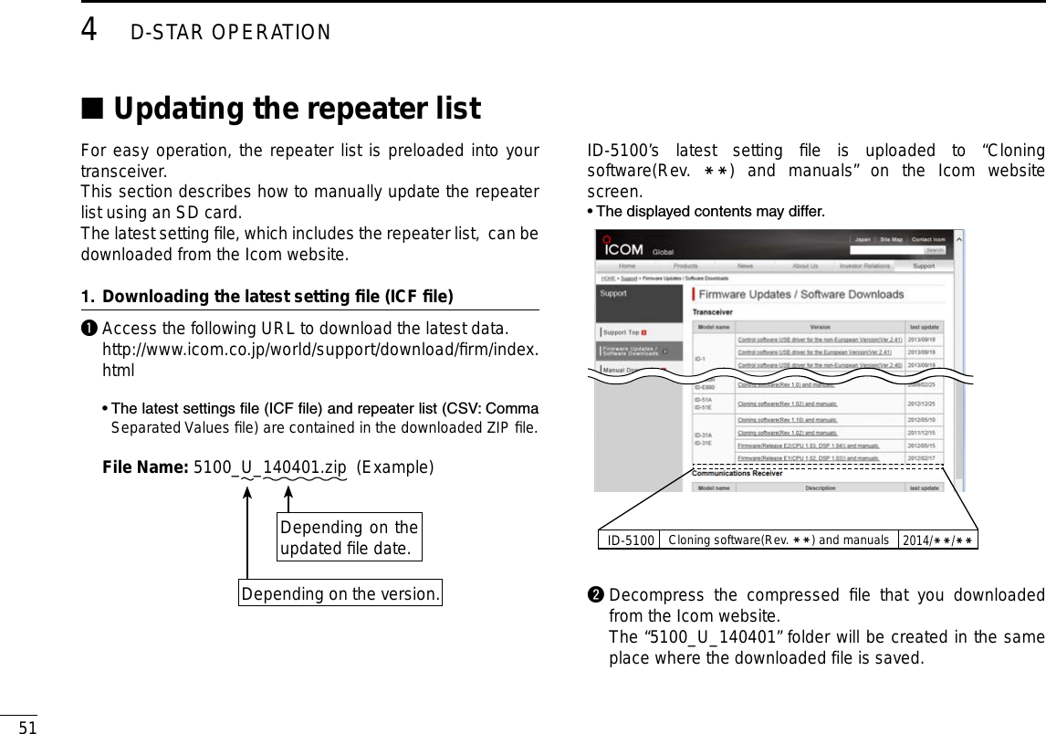
![New2001524D-STAR OPERATION4D-STAR OPERATIONContinued on the next page ☞Inserting the SD card into a PC2. e Insert the SD card into the SD card drive on your PC. • Icom recommends that you format all SD cards to be used with the ID-5100, even preformatted SD cards for PCs or other uses. (p. ??-??)See page ??-?? and ??-?? for details on inserting and removing the SD card.SD cardTransceiverto the external card readerPCCopying the latest ICF file to the SD card3. r Double-click the “5100_U_140401” folder created in the same place where the downloaded file is saved.t Copy the CSV file (Example: “5100_USA_140401.csv”) in the folder to [RptList] of the SD card. [ID-5100] > [CSV] > [RptList] The copied CSV file is placed hereDouble-ClickDouble-Click](https://usermanual.wiki/ICOM-orporated/348400/User-Guide-2227051-Page-65.png)
![534D-STAR OPERATIONNew2001 New2001Updating the repeater list (Continued) ■Inserting the SD card4. y Remove the SD card from your PC, and insert it into the transceiver’s slot.See page ??-?? for details on inserting the SD card into the transceiver.SD cardTransceiverfrom the external card readerPCIcom recommends that you save the current data before loading other data into the transceiver.Updating the repeater list5.u Touch [MENU].i Touch [Repeater list]. (SD Card > Import/Export > Import > Repeater list) • If the item is not displayed, touch [∫] or [√] one or more times to select another page. o Touch the CSV file to be loaded. (Example: “5100_USA_140401.csv”) • The “Keep 'SKIP' settings in Repeater List?” window appears.](https://usermanual.wiki/ICOM-orporated/348400/User-Guide-2227051-Page-66.png)
![New2001544D-STAR OPERATION4D-STAR OPERATION!0 Touch [YES] or [NO]. • When you touch [YES], the skip settings of the repeater list are retained. • When you touch [Cancel], returns to the “LOAD FILE” screen. !1 When the “Import file?” appears, Touch [YES]. • Starts to import. • While importing, “IMPORT” and a progress bar are displayed. !4 After importing ends, “COMPLETED!” appears. To complete the importing, reboot the transceiver.For your reference:If you copy the ICF file to [Setting] of the SD card, the re-peater list can be updated with the same procedures. In this case, touch “Load Setting.”(SD Card > Load Setting)In the LOAD FILE screen, touch “Repeater List Only.”](https://usermanual.wiki/ICOM-orporated/348400/User-Guide-2227051-Page-67.png)
![New200155New2001New2001RECORDING A QSO ONTO AN SD CARD5About the SD card ■The SD and SDHC cards are not available from Icom. Pur-chase separately.An SD card of up to 2 GB, or an SDHC of up to 32 GB, can be used with the ID-5100.Icom has checked the compatibility with the following SD and SDHC cards.(As of March 2014)Brand Type Memory sizeSanDisk®SD 2 GBSDHC4 GB8 GB16 GB32 GB• The above list does not guarantee the card’s performance.• Throughout the rest of this document, the SD card and an SDHC card are simply called SD cards.• Icom recommends that you format all SD cards to be used with the ID-5100, even preformatted SD cards for PCs or other uses.Saving the factory default data is recommended. Insert the card into the transceiver’s slot, and then touch [MENU]. Touch “SD Card,” and then “Save Setting” to save.NOTE:• Before using the SD card, read the instructions of the SD card thoroughly.• If you do any of the following, the SD card data may be corrupted or deleted. - You remove the SD card from the transceiver while ac-cessing the SD card. - You change the external power supply’s voltage while accessing the SD card. - You start the vehicle engine while accessing the SD card. - You drop, impact or vibrate the SD card.• Do not touch the contacts of the SD card.• The transceiver takes a longer time to recognize a high capacity SD card.• The SD card will get warm if used continuously for a long period of time.• The SD card has a certain lifetime, so data reading or writ-ing may not be possible after using it for a long time pe-riod.• When reading or writing data is impossible, the SD card’s lifetime has ended. In this case, purchase a new one. We recommend you make a backup file of the important data onto your PC.• Icom will not be responsible for any damage caused by data corruption of an SD card.](https://usermanual.wiki/ICOM-orporated/348400/User-Guide-2227051-Page-68.png)
![565RECORDING A QSO ONTO AN SD CARDNew20015RECORDING A QSO ONTOAN SD CARDNew2001Inserting the SD card ■Inserting the SD card DTurn OFF the transceiver. q Insert the card into the slot until it locks in place, and wmakes a ‘click’ sound. • “ ” is displayed when the SD card is inserted. • “ ” and “ ” alternately blink while accessing the SD card.NOTE: Before inserting, be sure to check the card direc-tion. If the card is forcibly or inversely inserted, it will dam-age the card and/or the slot.Terminalsfacing downCut corner sideFront panel(Main unit)SD cardDisplayedFormatting the SD card D• If you use a brand new SD card, format it by doing the following steps.• Formatting a card erases all its data. Before formatting any used card, back up its data onto your PC. Turn OFF the transceiver, and then insert the card into the qslot.Turn ON the transceiver. w • “ ” appears when the SD card is inserted.Touch [MENU]. e Touch “SD Card.” r • If the item is not displayed, touch [∫] or [√] one or more times to select the page. Touch “Format.” t • The conrmation window “Format OK?” appears. Touch [YES]. y • The formatting starts and the display shows the formatting prog-ress. • After formatting ends, the display automatically returns to the screen displayed before the “Format OK?” window.](https://usermanual.wiki/ICOM-orporated/348400/User-Guide-2227051-Page-69.png)
![575RECORDING A QSO ONTO AN SD CARDNew2001 New2001Recording a QSO audio ■Touch the Function group icon one or more times. q • When displaying the DR screen, selects the D-3 menu. • While in the VFO, Memory or Call CH mode, displays the F-3 menu.Touch [REC]. w • The “Recording started” dialog box appears, and voice recording starts. • “ ” is displayed while the transceiver is recording. • “ ” is displayed while the recording is paused. • Recording is continuous until you manually stop recording, or the card becomes full. • If the recording le’s content reaches 2GB, the transceiver auto-matically creates a new file, and continues recording. Touch the record icon. e • The “Stop recording?” dialog box appears. Touch [YES]. r • The “Recording stopped” dialog box appears, and voice record-ing stops. For your reference:When the PTT Automatic Recording function is set to ON in the MENU screen, the recording automatically starts when [PTT] is pushed.( Voice Memo > QSO Recorder > Recorder Set > PTT Auto REC)NOTE: Once the voice recording starts, it will continue until you stop recording, even if you turn OFF the trans-ceiver.](https://usermanual.wiki/ICOM-orporated/348400/User-Guide-2227051-Page-70.png)
![New2001585RECORDING A QSO ONTO AN SD CARD5RECORDING A QSO ONTO AN SD CARDRemoving the SD card ■PushPull out Removing the SD card while the transceiv- Der’s power is ONTouch [MENU]. q Touch “SD Card.” w • If the item is not displayed, touch [∫] or [√] one or more times to select the page. Touch “Unmount.” e • The conrmation window “Unmount OK?” appears. Touch [YES]. r • When the unmounting is completed, “Unmount is completed.” is displayed, then the display automatically returns to the screen displayed before the “Unmound OK?” window. Push in the SD card until a click sounds, and then carefully tpull it out.Removing the SD card DTurn OFF the power. q Push in the SD card until a wclick sounds, and then care-fully pull it out.Front panel(Main unit)Playing back the recorded audio ■Touch [MENU]. qTouch “Play Files.” w (Voice Memo > QSO Recorder > Play Files) • If the item is not displayed, touch [∫] or [√] one or more times to select another page. Touch the folder that contains the file you want to play. e • The le list is displayed. • The folder name is named yyyymmdd (y: year, m: month, d: day.)Touch the file that you want to play. r • The “VOICE PLAYER” screen is displayed, and the le starts to playback. • See the Full Instructions for details. Touch [MENU]. t • Stops the playback, and close the “VOICE PLAYER” screen.](https://usermanual.wiki/ICOM-orporated/348400/User-Guide-2227051-Page-71.png)
![59New2001New2001GPS OPERATION6GPS operation ■The transceiver has a built-in internal GPS receiver. You can check your current position, and transmit GPS data in the DV mode.GPS receive setting D Check whether or not the GPS receiver is receiving your posi-tion. The GPS icon blinks when searching for satellites. ➪ ➪ ➪ The GPS icon stops blinking when the minimum needed number of satellites is found. • It may take only a few seconds to receive. But depending on the environment, it may take a few minutes. If you have difficulties re-ceiving, we recommend that you try a different location.• When “GPS Select” item is set to “Manual,” the icon does not ap-pear. (GPS > GPS Set > GPS Select)Checking your GPS position ■You can check your current position.If you transmit while displaying the GPS position screen, the screen closes.But you can check your current position, RX position, and so on by touching the GPS icon while transmitting.Displaying Position Data DTouch the GPS icon. q Touch [GPS Position]. w • Opens the “GPS POSITION” screen.](https://usermanual.wiki/ICOM-orporated/348400/User-Guide-2227051-Page-72.png)
![New2001606CALLING A DESTINATION STATION6CALLING A DESTINATION STATION“GPS POSITION” screen (MY) Latitude TimeCompass direction top is North.Your course heading is East.Your course direction is 95° degrees.Shows My position Altitude Grid locator Speed LongitudeTouch [ e∫] or [√] one or more times. • Selects the page. GPS memory position screen (MEM)Received position screen (RX)My position screen (MY)GPS alarm position screen (ALM)Touch [ r]. • Closes the “GPS POSITION” screen.About the GPS Position screen D](https://usermanual.wiki/ICOM-orporated/348400/User-Guide-2227051-Page-73.png)
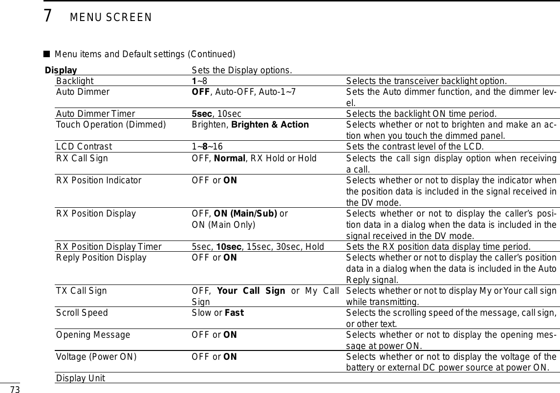
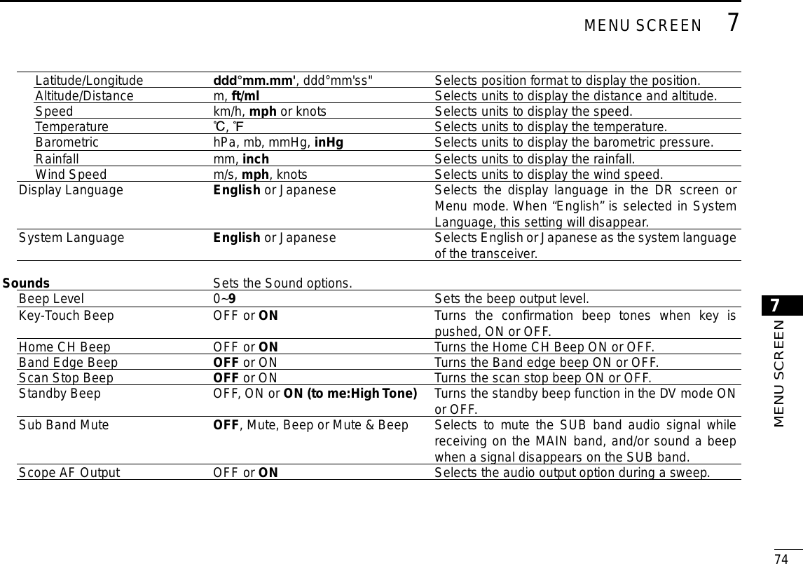
![New200161New2001MENU SCREEN7Menu item selection ■The Menu screen is used to program infrequently changed values or function settings.In addition to this page, see pages ?? through ?? for details of each item’s options and their default value.NOTE: The Menu system is constructed in a tree structure. You may go to the next tree level, or go back a level, de-pending on the selected item.Entering the Menu screen DExample: Set the Auto Power OFF function to “30 min.”Touch [MENU]. q Touch [ w∫] or [√] one or more times to select the page. • If you continuously hold down [∫] or [√], the items are quickly scrolled. • To set other item, touch [] to go back a tree level.Touch “Time Set.” e To return to the default setting, touch [QUICK] in step t, and then touch “Default,”.Touch “Auto Power OFF.” r • If you continuously touch [∫] or [√], the items are quickly scrolled. Touch “30min.” t Touch [MENU] y • Closes the Menu screen.](https://usermanual.wiki/ICOM-orporated/348400/User-Guide-2227051-Page-74.png)
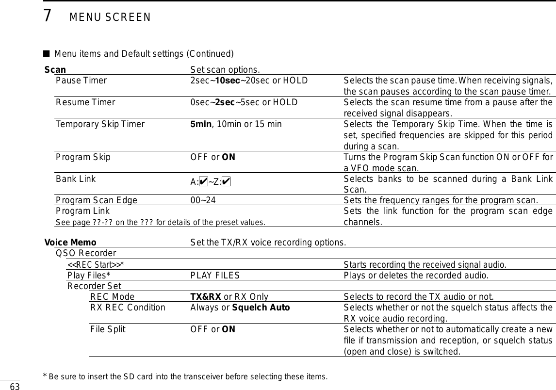
![New2001647MENU SCREEN7MENU SCREENPTT Auto REC OFF or ON Turns the PTT Automatic Recording function ON or OFF.Player SetSkip Time 3sec, 5sec, 10sec or 30secSets the Skip time to rewind or forward the recorded audio when you push the fast-rewind or fast-forward key during playback.DV Auto Reply* Records a voice audio to use the Auto Reply function in the DV mode.Voice TX Set microphone voice recording options.Record*T1~T4 Starts recording the microphone audio.TX SetRepeat Time 1sec~5sec~15sec Sets the repeat interval. The transceiver repeatedly transmits the recorded voice audio at this interval.TX Monitor OFF or ON The TX Monitor function outputs the TX voice audio from the speaker during voice transmission.<<TX>>* T1~T4, Repeat TX The transceiver transmits the recorded voice audio.GPS Set GPS options.GPS SetGPS Select OFF, Internal GPS or Manual Selects the position data source that the transceiver uses for its position data.Manual Position Manually enter your current position.GPS Out (To DATA Jack) OFF or ON Selects to output the GPS information to the [DATA] jackGPS TX ModeOFF Turns OFF the GPS TX function.D-PRSUnproto Address API510,DSTAR* Enters an unproto address, or keep the default.* Be sure to insert the SD card into the transceiver before selecting these items.](https://usermanual.wiki/ICOM-orporated/348400/User-Guide-2227051-Page-77.png)
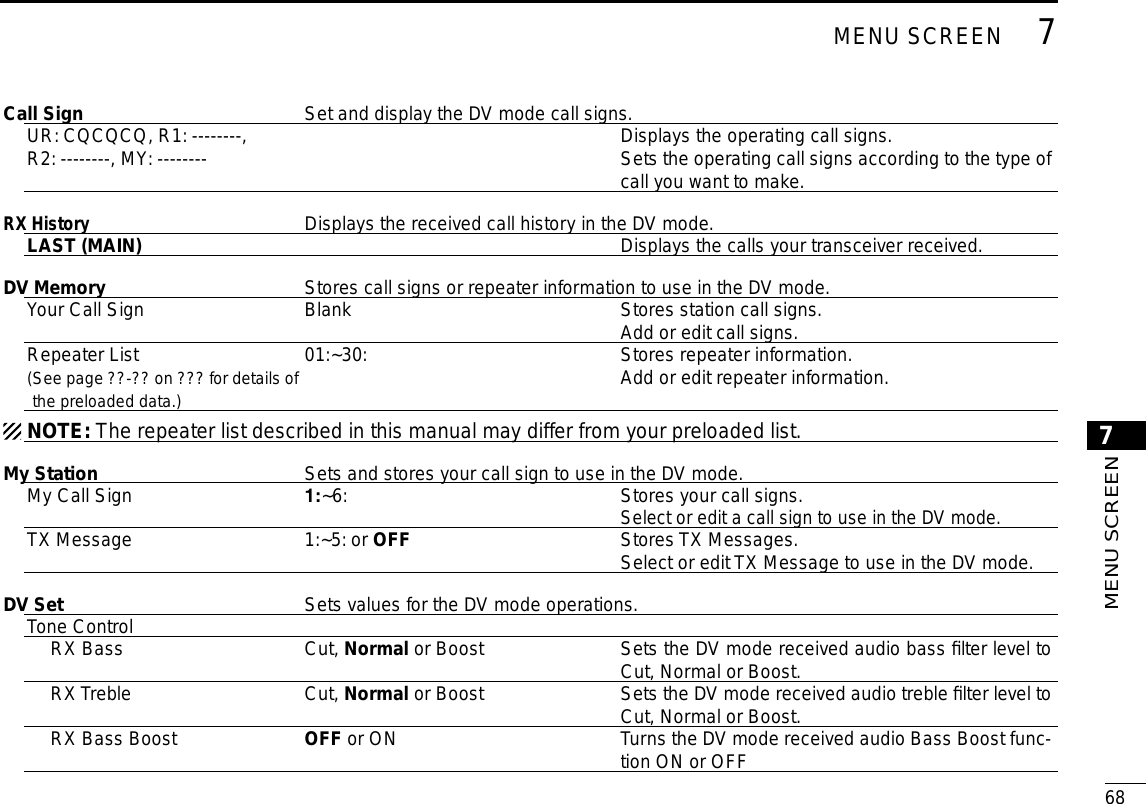
![697MENU SCREENNew2001 New2001TX Bass Cut, Normal or Boost Sets the DV mode transmit audio bass filter level to Cut, Normal or Boost.TX Treble Cut, Normal or Boost Sets the DV mode transmit audio treble filter level to Cut, Normal or Boost.Auto Reply OFF, ON, Voice, Position (Main Only) or Position (Main/Sub) Selects the Automatic Reply function.DV Data TX PTT or Auto Selects manually or automatically to transmit low speed data.Digital Monitor Auto, Digital or Analog Selects the DV mode RX monitoring when [SQL] is held down.Digital Repeater Set OFF or ON Turns the digital repeater setting function ON or OFF. This function is usable in any DV mode except using the DR function.DV Auto Detect OFF or ON Turns the DV mode automatic detect function ON or OFF.RX Record (RPT) ALL or Latest Only The transceiver can record the data of up to 50 indi-vidual calls.BK OFF or ON Turns the BK (Break-in) function ON or OFF. The BK function allows you to break into a conversation be-tween two stations with call sign squelch enabled.EMR OFF or ON Turns the EMR (Enhanced Monitor Request) com-munication mode ON or OFF.After turning OFF the transceiver, the EMR mode will be cancelled.EMR AF Level 0~19~39 Sets the audio output level when an EMR mode sig-nal is received.Menu items and Default settings (Continued) ■](https://usermanual.wiki/ICOM-orporated/348400/User-Guide-2227051-Page-82.png)
![New2001707MENU SCREEN7MENU SCREENSPEECH Sets the Speech functions.RX Call Sign SPEECH OFF, ON (Kerchunk) or ON (All) Selects the RX call sign speech function option while ON, or turn it OFF.RX>CS SPEECH OFF or ON Turns the RX>CS Speech function ON or OFF.DIAL SPEECH OFF or ON Turn the Dial Speech function ON or OFF.MODE SPEECH OFF or ON Turn the Operating Mode Speech function ON or OFF.SPEECH Language English or Japanese Selects either English or Japanese as the desired speech language.Alphabet Normal or Phonetic Code Selects the alphabet character announcement type.SPEECH Speed Slow or Fast Selects Slow or Fast speech speedSPEECH Level 0~7~9 Sets the volume level for the voice synthesizer.DTMF Sets the DTMF Memory functions.DTMF Memory d0:~d9:, dA:~dD:, d*: or d#: Shows a list of the DTMF memory channels. The DTMF memory can store up to 24-digit DTMF code.DTMF Speed 100ms, 200ms, 300ms or 500ms Selects the DTMF transfer speed.QSO/RX Log Sets the QSO/RX History Log options.QSO Log*1OFF or ON Selects to make a communication log on the SD card, or not.RX History Log*1OFF or ON Selects to make a DV mode's receive history log on the SD card, or not.CSV FormatSeparator/Decimal Sep [,] Dec [.]*2, Sep [;] Dec [.] or Sep [;] Dec [,] Selects the separator and the decimal character for the CSV format.Date yyyy/mm/dd, mm/dd/yyyy*2 or dd/mm/yyyy Selects the date format.*1 Be sure to insert the SD card into the transceiver before selecting these items.*2 The default value may differ, depending on the transceiver version.](https://usermanual.wiki/ICOM-orporated/348400/User-Guide-2227051-Page-83.png)
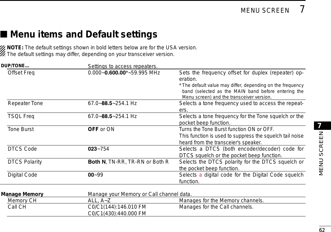
![717MENU SCREENNew2001 New2001Function Sets various function’s options.Squelch/ATT Select OFF, S-MeterSquelch, ATT Selects to use the S-Meter Squelch or the Attenuator function for the [SQL] control.Squelch Delay Short, Long Selects to shorten or lengthen the time until the squelch opens.Fan Control Slow, Mid, Fast or Auto Selects the cooling fan control condition.Dial Speed-UP OFF or ON Turns the dial speed acceleration ON or OFF.Auto Repeater OFF or ON (DUP), ON (DUP,TONE) Turns the Auto Repeater function ON or OFF.Remote MIC Key Selects the key function for [F-1] or [F-2] on the sup-plied remote-control microphone.During RX/Standby [F-1]:BAND/BANK [F-2]:MONITOR Selects the key function to be used while receiving or in the standby mode.During TX [F-1]:T-CALL [F-2]:--- Selects the key function to be used while transmit-ting.Up/Down MIC Key Selects the key function for [UP] or [DN] on the op-tional hand microphone.During RX/Standby [UP]:UP [DN]:DOWN Selects the key function to be used while receiving or in the standby mode.During TX [UP]:--- [DN]:--- Selects the key function to be used while transmit-ting.One-Touch PTT(Remote MIC) OFF or ON Turns the One-Touch PTT function ON or OFF.PTT Lock OFF or ON Turns the PTT Lock function ON or OFF.Busy Lockout OFF or ON Turns the Busy Lockout function ON or OFF.Time-Out Timer OFF, 1min, 3min, 5min, 10min, 15min or 30min Selects the Time-Out Timer time options. Active Band Single or All Allows continuous frequency selection across all bands by rotating [DIAL].MIC Gain 1~2~4 Sets the microphone sensitivity to suit your prefer-ence.Menu items and Default settings (Continued) ■](https://usermanual.wiki/ICOM-orporated/348400/User-Guide-2227051-Page-84.png)
![New2001727MENU SCREEN7MENU SCREENTouch Operation (Sub) Main Select or Function Select Sets the touch operation on the SUB band display.Keyboard Type Ten-key, Full keyboard Selects the keyboard input type to enter a call sign, memory name, and so on.Data Speed 4800bps or 9600bps Selects the data transmission speed for low-speed communication, or between the [DATA] jack and ex-ternal modules like a GPS receiver, and so on.CI-VCI-V Address 01~8Ch~DF Sets the transceiver's unique CI-V hexadecimal ad-dress code.CI-V Baud Rate 4800, 9600, 19200 or Auto Sets the CI-V code transfer speed.CI-V TransceiveOFF or ON Turns the CI-V Transceive function ON or OFF.CI-V Bluetooth➝REMOTE transceive Address 00h~DFh Sets the address to inhibit the external control with CI-V for the transceiver through the [SP2] (REMOTE) jack.HeterodyneHeterodyne (A BAND VHF)Normal or ReverseEffective to eliminate internal spurious that may oc-cur in a rare combination of dual band frequencies, when operating VHF on the A band.Heterodyne (A BAND UHF)Normal or ReverseEffective to eliminate internal spurious that may oc-cur in a rare combination of dual band frequencies, when operating UHF on the A band.Heterodyne (B BAND UHF)Normal or ReverseEffective to eliminate internal spurious that may oc-cur in a rare combination of dual band frequencies, when operating UHF on the B band.Power OFF (With No Controller) OFF or ON Selects whether or not to automatically turn OFF the transceiver when the controller is disconnected from the transceiver.](https://usermanual.wiki/ICOM-orporated/348400/User-Guide-2227051-Page-85.png)
![757MENU SCREENNew2001 New2001Time Set Sets the Time options.Date/TimeDATE 2000/01/01~2099/12/31 Sets the current date.TIME 0:00~23:59 Sets the current time.GPS Time Correct OFF or Auto Sets to automatically correct the time using a GPS signal.UTC Offset –14:00~±0:00~+14:00 Enters the time difference between UTC and the lo-cal time.Auto Power OFF OFF, 30min, 60min, 90min or 120min Turns the Auto power OFF function ON or OFF.SD Card* Sets the SD card options.Load SettingFile selection ALL, Except My Station, Repeater List Only Loads the settings file to the transceiver.Save Setting<<New File>> Saves the settings as a new file.File selection Saves the settings in a selected file.Import/ExportImport Your Call Sign, Repeater List or GPS Memory Selects to import the repeater list, UR call sign or GPS memory data in the CSV format file.Export Your Call Sign, Repeater List or GPS Memory Selects to export the repeater list, UR call sign or GPS memory data in the CSV format file.CSV FormatSeparator/Decimal Sep[,]Dec[.], Sep [;] Dec [.] or Sep [;] Dec [,] Selects the separator and the decimal character for the CSV format.Date yyyy/mm/dd, mm/dd/yyyy ordd/mm/yyyy Selects the date format.Menu items and Default settings (Continued) ■* Be sure to insert the SD card into the transceiver before selecting these items.](https://usermanual.wiki/ICOM-orporated/348400/User-Guide-2227051-Page-88.png)
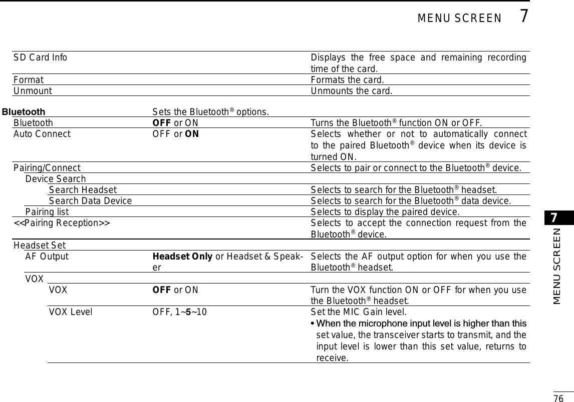
![777MENU SCREENNew2001 New2001VOX Delay 0.5sec, 1.0sec, 1.5sec, 2.0sec, 2.5sec or 3.0sec Sets the VOX Delay time for the transmitter stays ON after you stop speaking before the VOX switches to receive.VOX Time-Out Timer OFF, 1min, 2min, 3min, 4min, 5min, 10min or 15min Sets the VOX Time-Out Timer to prevent an acciden-tal prolonged transmission.Icom Headset Sets to use the optional Icom Bluetooth® headset (VS-3).Power Save OFF or ON Sets the Power save function to prolong the headset battery.Out-Touch PTT OFF or ON Sets the One-Touch PTT function to toggle between transmission and reception by pushing [PTT].PTT Beep OFF or ON Sets to sound a beep when you push [PTT].Custom Key Beep OFF or ON Sets to sound a beep when you push the custom key ([PLAY]/[FWD]/[RWD]).Custom Key [PLAY]:---, [FWD]:UP,[RWD]: DOWN Selects the key function of the custom key ([PLAY]/[FWD]/[RWD]).Data Device Set Sets the data device options.Serialport Function CI-V (Echo Back OFF), CI-V(Echo Back ON) or DV Data Selects to transmit or receive the CI-V command or the DV data.Bluetooth Device Information Shows the optional UT-133 Bluetooth® UNIT informa-tion.Reset Bluetooth Device Selects to reset the optional UT-133 Bluetooth® UNIT.Menu items and Default settings (Continued) ■](https://usermanual.wiki/ICOM-orporated/348400/User-Guide-2227051-Page-90.png)
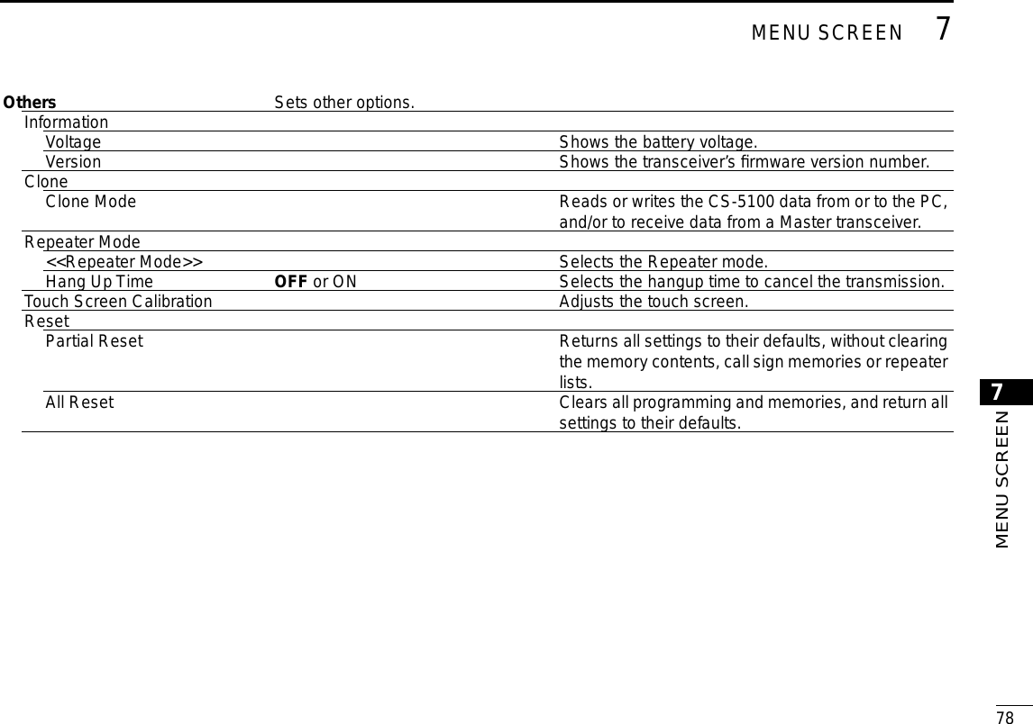
![85New2001New2001MAINTENANCE9New2001Resetting ■Occasionally, erroneous information will be displayed, for ex-ample, when first applying power. This may be caused exter-nally by static electricity or by other factors.If this problem occurs, turn OFF power.After waiting a few seconds, turn ON power again. If the prob-lem is still there, perform a Partial reset or an All reset.A Partial reset resets the operating settings to their default values (VFO frequency, VFO settings, menu contents) with-out clearing the items below:• Memory channel contents • Scan Edge contents• Call channel contents • Call sign memories• Message data • DTMF memory contents• GPS Memory contents • Repeater listBE CAREFUL! An All reset clears all programming and returns all settings to their factory defaults. See the Full Instructions for details.Partial Reset DTouch [MENU]. q Touch “Reset.” w (Manage Memory > Others > Reset) • If the item is not displayed, touch [∫] or [√] one or more times to select the page. Touch “Partial Reset.” e Touch [YES]. r • The transceiver displays "PARTIAL RESET," then the partial reset is completed.](https://usermanual.wiki/ICOM-orporated/348400/User-Guide-2227051-Page-98.png)