ICOM orporated 348400 Dual Band Transceiver User Manual
ICOM Incorporated Dual Band Transceiver
User Manual
This device complies with Part 15 of the FCC Rules. Operation is
subject to the following two conditions: (1) this device may not cause
harmful interference, and (2) this device must accept any interference
received, including interference that may cause undesired operation.
WARNING: MODIFICATION OF THIS DEVICE TO RECEIVE CEL-
LULAR RADIOTELEPHONE SERVICE SIGNALS IS PROHIBITED
UNDER FCC RULES AND FEDERAL LAW.
BASIC INSTRUCTIONS
New2001
ID-5100A
DUAL BAND TRANSCEIVER
ID-5100E

i
New2001New2001
FOREWORD
Thank you for purchasing this fine Icom product. The ID-
5100A and ID-5100E DUAL BAND TRANSCEIVER are designed
and build with Icom’s superior technology and craftsmanship
combining traditional analog technologies with the new digital
technology, Digital Smart Technologies for Amateur Radio (D-
STAR), for a balanced package.
With proper care, this product should provide you with years
of trouble-free operation.
We thank you for making your ID-5100A or ID-5100E your
transceiver of choice, and hope you agree with Icom’s philos-
ophy of “technology first.” Many hours or research and devel-
opment went into the design of your ID-5100A or ID-5100E.
EXPLICIT DEFINITIONS
WORD DEFINITION
R DANGER! Personal death, serious injury or an ex-
plosion may occur.
R WARNING! Personal injury, fire hazard or electric
shock may occur.
CAUTION Equipment damage may occur.
NOTE Recommended for optimum use. No risk
of personal injury, fire or electric shock.
IMPORTANT
READ ALL INSTRUCTIONS carefully and completely
before using the transceiver.
SAVE THIS INSTRUCTION MANUAL— This in-
struction manual contains basic operating instructions for the
ID-5100A/ID-5100E.
Icom, Icom Inc. and the Icom logo are registered trademarks of Icom
Incorporated (Japan) in Japan, the United States, the United King-
dom, Germany, France, Spain, Russia and/or other countries.
Adobe and Adobe Reader are either registered trademarks or trade-
marks of Adobe Systems Incorporated, in the United States and/or
other countries.
Microsoft, Windows and Windows Vista are registered trademarks of
Microsoft Corporation in the United States and/or other countries.
The Bluetooth® work mark and logos are registered trademarks
owned by Bluetooth SIG, Inc. and any use of such marks by Icom
inc. is under license.
All other products or brands are registered trademarks or trademarks
of their respective holders.
New2001New2001
ii
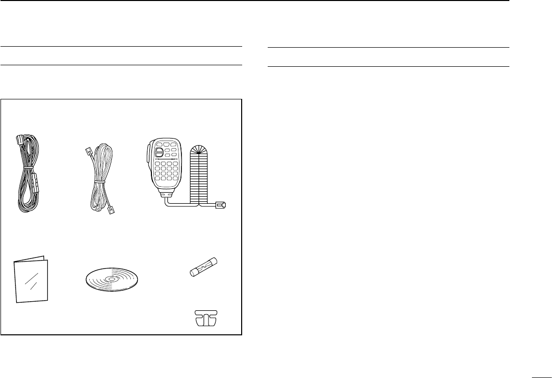
SUPPLIED ACCESSORIES
The following accessories are supplied with the transceiver.
DC power
cable Controller cable
(3.5 m:11.4 ft) Microphone
(HM-207)
CD
( Instruction manual
[Full instructions])
Operating guide
( Includes the CS-5100
CLONING SOFTWARE)
Spare fuse
(FGB 20 A)
Microphone
hanger
DWhen using the GPS receiver
• GPS signals cannot pass through metal objects. When us-
ing the ID-5100A or ID-5100E inside a vehicle, you may not
receive GPS signals. We recommend you use it near a win-
dow. Please avoid the areas:
1. where it will block the driver’s view.
2. where the air bags could deploy.
3. where it becomes a driving obstacle.
• The Global Positioning System (GPS) is built and operated
by the U.S. Department of Defence. The Department is re-
sponsible for accuracy and maintenance of the system. Any
changes by the Department may affect the accuracy and
function of the GPS system.
• When the GPS receiver is activated, please do not cover
the remote controller with anything that will block the satel-
lite signals.
• The GPS receiver may not work if used in the following loca-
tions:
1. Tunnels or high-rise buildings
2. Underground parking lots
3. Under a bridge or viaduct
4. In remote forested areas
5. Under bad weather conditions (rainy or cloudy day)
IMPORTANT NOTES
iii
New2001New2001
Touch screen precautions D
Briefly touching the controller’s touch operates the function.
• The touch screen may not properly work when LCD protec-
tion film or sheet is attached.
• Touching the screen with nger nails, sharp topped object
and so on, or touching the screen hard may damage the
screen.
• Tablet PC’s operations such as ick input, pinch in and pinch
out cannot be performed with this touch screen.
Touch screen maintenance D
• If the touch screen becomes dusty or dirty, wipe it clean with
a soft, dry cloth.
• When you wipe the touch screen, be careful not to push it
too hard or scratch it with finger nails. Otherwise you may
damage the touch screen.
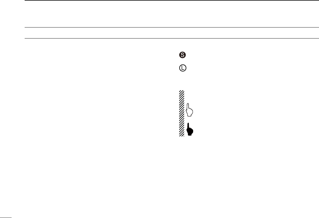
Touch operation D (Short touch): If the display is touched briefly, one short
beep sounds.
(Long touch): If the display is touched for 1 second, one
short and one long beep sound.
• After the beep, the operation is enabled.
In the instruction manual, the touch operation is described
as shown below.
If the display is touched briefly, one short beep
sounds.
If the display is touched for 1 second, one short and
one long beep sound.
About the Touch area D
Areas you can touch for various operations are shown to the
right.
• This page describes the main operations of the touch screen.
See the instruction manual for other operations.
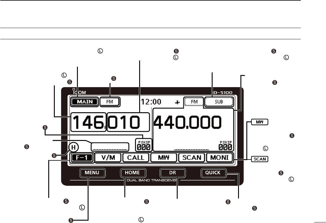
ABOUT THE TOUCH SCREEN
iv
ID-5100
Function menu selection:
Displays
the Function menu list:
Displays the QUICK
Menu:
Function menu
operations
• The following operations
are examples.
Sets MAIN band to the
right side:
Sets MAIN band to the right side:
Dual or Single band display selection:
• In the Single band, touch [B] to set the B band as
the MAIN band.
Displays the DR screen:
• D-STAR settings can easily be
made.
Home CH selection:
• Selects the Home CH that you
set in the QUICK Menu.
Home CH setting:
Displays the Menu screen:
Cancels “MHz” tuning:
Tuning step selection:
Displays the Memory
Write window:
Writes to a blank
CH:
Scan type
selection:
Starts a scan:
• The last used scan
starts.
Dual or Single band display selection:
Operating mode
selection:
“MHz” tuning selection:
Operating band selection:
TX power selection:
• MAIN band: Used for TX or radio’s settings
• SUB band: Used for the Dualwatch operation
ABOUT THE TOUCH SCREEN (Continued)
Displays the Monitor
function:
Sets the Mode:
v
New2001 New2001
The following instructions and installers are included on the
CD.
•Basicinstructions
Basic operating instructions, and are the same instructions
that are in this manual
•FullInstructions
Full operating instructions, and more details are described
than in this manual
•OperatingGuide
Operating guide for using the touch screen, Menu items and
Quick menu items. Contains the same information that is in
the supplied leaflet.
•HAMradioTerms
A glossary of HAM radio terms
•CS-5100Instructionmanual
Instructions for the CS-5100 cloning software installation
and use
•CS-5100Installer
Installer for the CS-5100 cloning software
•Adobe® Reader® Installer
Installer for Adobe® Reader®
ABOUT THE SUPPLIED CD
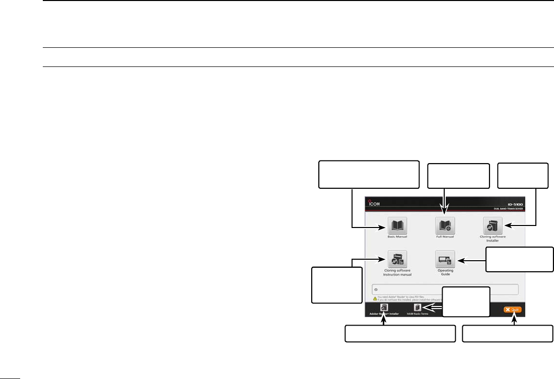
DStarting the CD
Insert the CD into the CD drive. q
• Double click “Autorun.exe” on the CD.
• Depending on the PC setting, the Menu screen shown
below is automatically displayed.
Click the desired button to open the file. w
• To close the Menu screen, click [Quit].
A PC with the following Operating System is required.
• Microsoft® Windows® 8.1, Microsoft® Windows® 8, Micro-
soft® Windows® 7 , Microsoft® Windows Vista® or Microsoft®
Windows® XP
To read the guide or instructions, Adobe® Reader® is required. If you
have not installed it, please install the Adobe® Reader® on the CD or
downloaded it from Adobe Systems Incorporated’s web
site.
Quits the menu screenInstalls the Adobe® Reader®
Opens the
Glossary
Installs the
CS-5100
Opens the Full
Instructions
Opens the
Operating Guide
Opens the Basic
Instructions (this manual)
Opens the
CS-5100
Instructions

New2001
vi
1
2
3
4
5
6
7
8
9
10
11
12
13
14
15
16
17
18
19
R DANGER HIGH VOLTAGE! NEVER touch an an-
tenna connector during transmission. This may result in an
electrical shock or burn.
R WARNING RF EXPOSURE! This transceiver emits
Radio Frequency (RF) energy. Extreme caution should be ob-
served when operating this transceiver. If you have any ques-
tions regarding RF exposure and safety standards please
refer to the Federal Communications Commission Office of
Engineering and Technology’s report on Evaluating Compli-
ance with FCC Guidelines for Human Radio Frequency Elec-
tromagnetic Fields (OET Bulletin 65).
R WARNING! NEVER operate the transceiver while
driving a vehicle. Safe driving requires your full attention—
anything less may result in an accident.
R WARNING! NEVER operate the transceiver with an
earphone or other audio accessories at high volume levels.
Hearing experts advise against continuous high volume op-
eration. If you experience a ringing in your ears, reduce the
volume level or discontinue use.
R WARNING! NEVER connect the transceiver to an AC
outlet. This may pose a fire hazard or result in an electric
shock.
R WARNING! NEVER connect the transceiver to a
power source of more than 16 V DC. This will damage the
transceiver.
R WARNING! NEVER connect the transceiver to a
power source using reverse polarity. This will damage the
transceiver.
R WARNING! NEVER cut the DC power cable between
the DC plug and fuse holder. If an incorrect connection is
made after cutting, the transceiver may be damaged.
R WARNING! NEVER let metal, wire or other objects
touch any internal part or connectors on the rear panel of the
transceiver. This may result in an electric shock or this could
cause a fire or damage the transceiver.
R WARNING! NEVER operate or touch the transceiver
with wet hands. This may result in an electric shock or may
damage the transceiver.
R WARNING! Immediately turn the transceiver power
OFF and remove the power cable if it emits an abnormal
odor, sound or smoke. Contact your Icom dealer or distributor
for advice.
CAUTION: NEVER expose the transceiver to rain, snow
or any liquids.
PRECAUTIONS

vii
New2001 New2001
CAUTION: NEVER change the internal settings of the
transceiver. This may reduce transceiver performance and/or
damage to the transceiver.
CAUTION: NEVER place the transceiver where normal
operation of the vehicle may be hindered or where it could
cause bodily injury.
DO NOT operate the transceiver near unshielded electrical
blasting caps or in an explosive atmosphere.
DO NOT push the PTT when not actually desiring to trans-
mit.
DO NOT use harsh solvents such as benzine or alcohol to
clean the transceiver, as they will damage the transceiver’s
surfaces. If the transceiver becomes dusty or dirty, wipe it
clean with a soft, dry cloth.
DO NOT use or place the transceiver in areas with tem-
peratures below –10°C (+14°F) or above +60°C (+140°F). Be
aware that temperatures on a vehicle’s dashboard can exceed
+80°C (+176°F) in direct sunlight, resulting in permanent dam-
age to the transceiver if left there for extended periods.
DO NOT place the transceiver in excessively dusty environ-
ments or in direct sunlight.
DO NOT place the transceiver against walls or putting anything
on top of the transceiver. This will obstruct heat dissipation.
Place the transceiver in a secure place to avoid inadvertent
use by children.
During mobile operation, NEVER place the transceiver
where air bag deployment may be obstructed.
During mobile operation, DO NOT place the transceiver
where hot or cold air blows directly onto it.
During mobile operation, DO NOT operate the transceiver
without running the vehicle’s engine. When the transceiver’s
power is ON and your vehicle’s engine is OFF, the vehicle’s
battery will soon become exhausted.
Make sure the transceiver power is OFF before starting the
vehicle engine. This will avoid possible damage to the trans-
ceiver by ignition voltage spikes.
During maritime mobile operation, keep the transceiver and
microphone as far away as possible from the magnetic navi-
gation compass to prevent erroneous indications.
BECAREFUL! The rear panel will become hot when op-
erating the transceiver continuously for long periods of time.
Use Icom microphones only (supplied or optional). Other
manufacturer’s microphones have different pin assignments,
and may damage the transceiver.
PRECAUTIONS (Continued)

New2001
viii
TABLE OF CONTENTS
FOREWORD .........................................................................i
EXPLICIT DEFINITIONS .......................................................i
IMPORTANT ..........................................................................i
SUPPLIED ACCESSORIES ................................................. ii
IMPORTANT NOTES ............................................................ii
ABOUT THE TOUCH SCREEN ........................................... iii
ABOUT THE SUPPLIED CD ................................................v
PRECAUTIONS ...................................................................vi
TABLE OF CONTENTS ......................................................viii
NEW FUNCTIONS ....................................... x–xii
1 PANEL DESCRIPTION ........................... 1–10
Controller — Front panel ■ .............................................1
Controller — Display (Touch screen) ■ ..........................2
Main unit — Front and rear panels ■ .............................7
Microphone (HM-207) ■ .................................................8
2 BASICOPERATION .............................. 11–18
Power ON the power ■ .................................................11
Setting audio volume and squelch level ■ ....................11
Selecting a tuning step ■..............................................11
Selecting the watch mode ■ .........................................12
Selecting the operating band ■ ....................................13
Direct frequency input ■ ...............................................14
Selecting the Mode and the DR function ■ ..................15
Transmitting ■ ...............................................................16
Selecting the operating mode ■ ...................................17
Lock function ■ .............................................................17
Home channel function ■ .............................................18
Speech function ■ ........................................................18
3 MEMORY MANAGEMENT .................... 19–20
Writing a Memory channel ■ ........................................19
Checking the programmed Memory contents ■ ...........19
4 D-STAROPERATION ............................ 21–54
Unique features of D-STAR ■ .......................................21
D-STAR Introduction ■ .................................................22
About the DR (D-STAR Repeater) function ■ ...............22
Way to communicate ■ with the DR function ...............23
Enter your call sign into the transceiver ■ ....................24
Register your call sign at a gateway repeater ■ ...........27
Making a Simplex call ■ ...............................................29
Accessing repeaters ■ .................................................31
Using the RX history ■ .................................................33
Capturing a call sign ■ .................................................35
Making a Local area call ■ ...........................................37
Making a Gateway Repeater call ■ ..............................39
Calling an individual station ■ ......................................41

New2001New2001
ix
New2001
TABLE OF CONTENTS
Troubleshooting ■ .........................................................43
Reflector operation ■ ....................................................45
Updating the repeater list ■ ..........................................51
5 RECORDING A QSO ONTO
AN SD CARD ........................................ 55–58
About the SD card ■.....................................................55
Inserting the SD card ■ ................................................56
Recording a QSO audio ■ ............................................57
Playing back the recorded audio ■ ...............................58
Removing the SD card ■ ..............................................58
6 GPS OPERATION ................................. 59–60
GPS operation ■ ..........................................................59
Checking ■your GPS position .....................................59
7 MENU SCREEN .................................... 61–78
Menu item selection ■ ..................................................61
Menu items and Default settings ■ ...............................62
Connect controller to main unit ■ .................................79
8 INSTALLATION AND CONNECTIONS . 79–84
Microphone connection ■ .............................................79
DC power supply connection ■ ....................................79
Remote installation ■ ...................................................80
Installing in a vehicle ■ .................................................81
Antenna installation ■...................................................82
Battery connection ■ ....................................................83
9 MAINTENANCE .................................... 85–86
Resetting ■ ...................................................................85
Power protect function ■ ..............................................86
Spurious signals ■ .......................................................86
Fuse replacement ■ .....................................................86
10INFORMATION ............................................ 87
COUNTRY CODE LIST .................................................87
FCC INFORMATION ......................................................87
INDEX .........................................................88–??
New2001
x
NEW FUNCTIONS
New2001
NEW FUNCTIONS
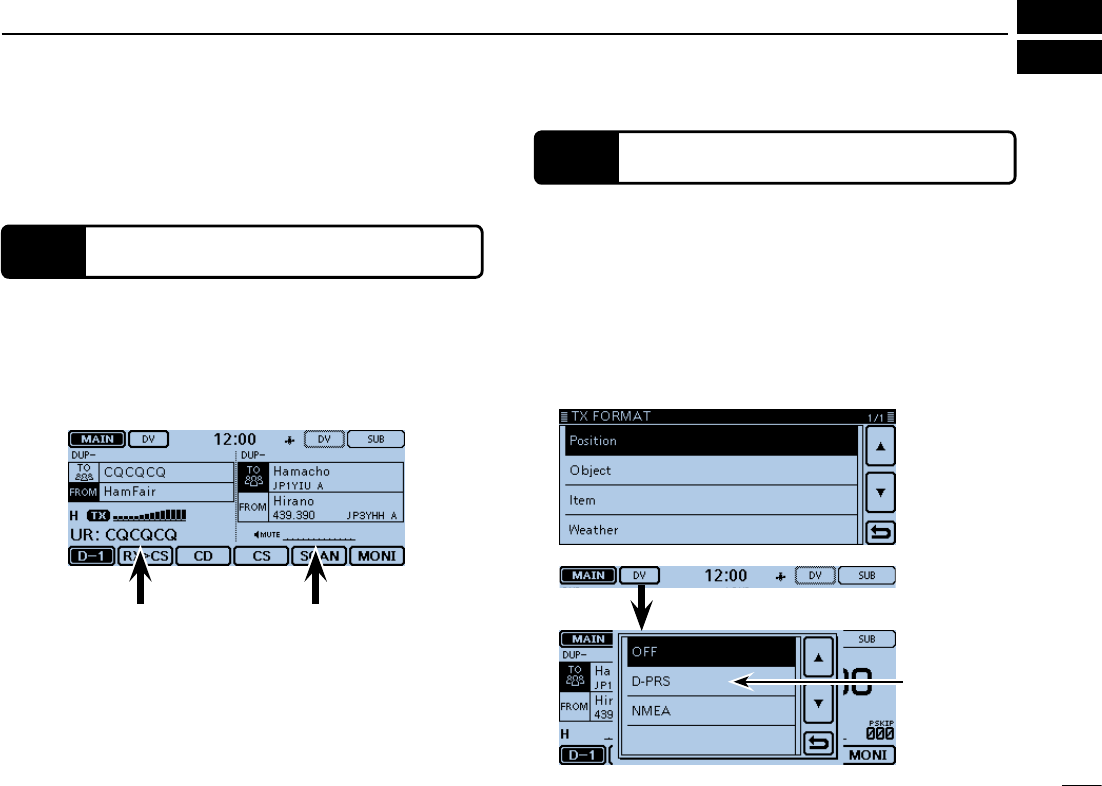
1Two band monitoring in the DV mode
2Add-onfunctionsforD-PRS
This section describes the new functions built into the ID-
5100A/E.
• See the Full Instructions for more details.
The transceiver can simultaneously monitor two different fre-
quencies in the DV mode. Or, while operating in the Simplex
mode on the MAIN band, you can monitor a D-STAR repeater
on the SUB band.
• See Section 2 of the Full Instructions for details.
D-PRS enables the transceiver to transmit or receive the Ob-
ject, Item or Weather data in addition to position data.
With the D-PRS add-on functions, you can receive informa-
tion such as an event, traffic, emergency or weather while
making a voice call in the DV mode.
• See Section 8 of the Full Instructions for details.
D-PRS “TX FORMAT” screen in the Menu screen.
(GPS > GPS TX Mode > D-PRS > TX Format)
MAIN band
(for TX and RX)
Touch to set the
GPS TX format
to “D-PRS.”
SUB band
(for RX)
xi
NEW FUNCTIONS
New2001
xi
New2001New2001
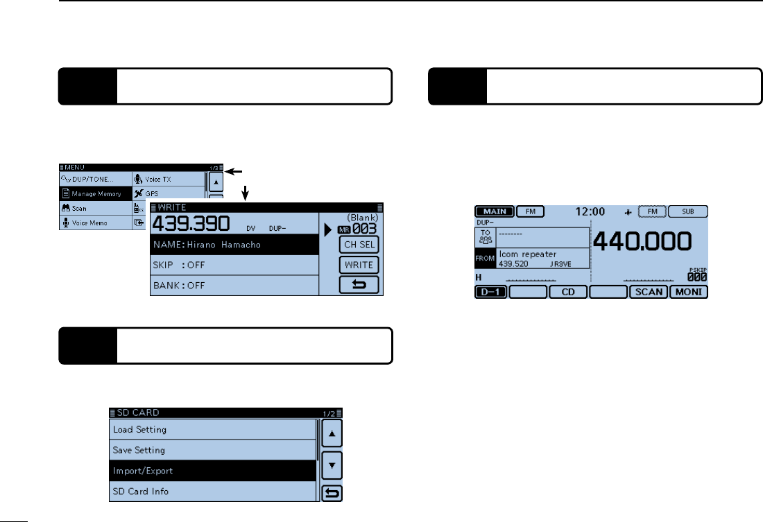
3Memory management
4Import and Export the CSV format file
5Near FM Repeater search function
You can easily edit the Memory or Call channel contents in
the “MANAGE MEMORY” screen. You can view the contents
on a list. (p. ??)
You can easily import and export the repeater list. (p. ??)
• An SD card is required.
You can enter the FM repeater data using the DR function.
The function can find only FM repeaters in your transceiver's
repeater list.
• See Section 8 of the Full Instructions for details.
“MANAGE MEMORY” item
Memory edit screen
When the FM repeater is selected.
New2001
xii
NEW FUNCTIONS
New2001
NEW FUNCTIONS
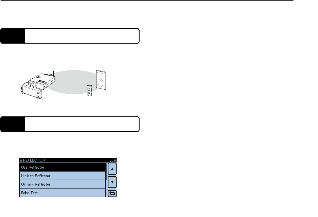
6Bluetooth® operation
Installing the optional UT-133 Bluetooth® UNIT allows you to
use a variety of Bluetooth® products.
• See Section 15 of the Full Instructions for details.
Bluetooth®
VS-3
Android device
(third party)
7Calling through a reflector
When you link to a reflector, you can listen to activity on all
the repeaters that are connected to the reflector, and easily
make contacts. (p. ??)
1
New2001New2001
PANEL DESCRIPTION
1New2001
ID-5100
qq
ww
e
rr
e
y u i o
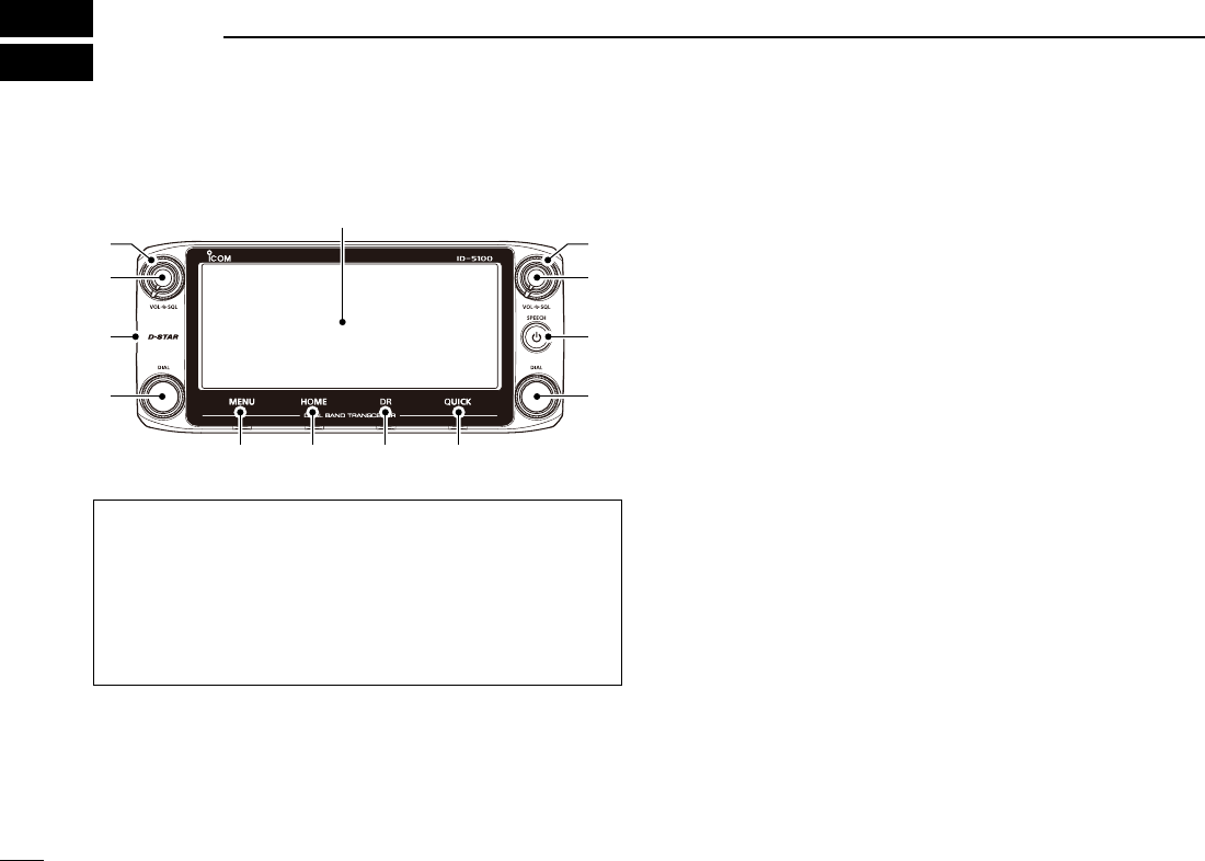
Display
q SQUELCH CONTROL [SQL]
Rotate to adjust the squelch level. (p. ??-??)
• Normally, set the squelch level to where noise and the “BUSY”
icon just disappear. (closed)
• You can use the S-Meter Squelch or Attenuator function by rotat-
ing the control clockwise beyond the center position. (p. ??-??)
About control’s operation
In the Dualwatch mode, the left side controls are used for
the left side band, and the right side controls are used for
the right side.
In the Single watch mode, the left side controls are used
for the A band, and the right side controls are used for the
B band.
Controller — Front panel ■w VOLUME CONTROL [VOL]
Rotate to adjust the audio level. (p. ??-??)
e MAIN UNIT CONNECTOR
Connect the controller to the Main unit using the supplied
control cable. (p. ??-??)
r TUNING DIAL [DIAL]
In the VFO mode, rotate to select the operating fre- ➥quency, and in the Memory mode, rotate to select a
Memory channel. (pp. ??-??, ??-??)
In the Menu screen or Quick Menu window, rotate to ➥select a desired option or value. (pp. ??-??, ??-??)
While scanning, rotate to change the scanning direc- ➥tion. (p. ??-??)
t POWER KEY [PWR]
Hold down for 1 second to turn power ON or OFF. (p. ➥??)
Push to audibly announce the operating frequency, ➥mode or a selected call sign. (p. ??-??)
y [MENU] (Touch screen) (p. ??-??)
Touch to open the Menu screen.
u [HOME] (Touch screen) (p. ??-??)
Touch to select the Home channel.
i [DR] (Touch screen) (p. ??-??)
Touch to open the DR screen.
o [QUICK] (Touch screen) (p. ??-??)
Touch to open the Quick Menu window.
New2001
2
1
PANEL DESCRIPTION
New2001
1
PANEL DESCRIPTION
q w
Dualwatch mode Single watch mode (A band)
Single watch mode (B band)
In the Single watch mode: A band In the Single watch mode: B band
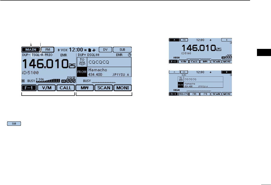
Controller — Display (Touch screen) ■
qMAIN/SUBBANDICON (p. ?-?)
In the Dualwatch mode, this icon will be highlighted to indi-
cate the MAIN band.
“” is displayed on the SUB band.
w TONE/DIGITAL SQUELCH ICONS
Displayed when you set any tone or digital squelch function.
(Mode:FM/FM-N)
“ TONE” is displayed while the Repeater Tone Encoder ➥is ON.
“ TSQL ➥S” is displayed while the Pocket Beep func-
tion with CTCSS is ON.
“ TSQL” is displayed while the Tone squelch function is ON. ➥
“ DTCS ➥S” is displayed while the Pocket Beep func-
tion with DTCS is ON.
“ DTCS” is displayed while the DTCS squelch function ➥is ON.
“ TSQL-R” is displayed while the Reverse Tone squelch ➥function is ON.
“ DTCS-R” is displayed while the reverse DTCS squelch ➥function is ON.
(Mode: DV)
“ DSQL ➥S” is displayed while the Pocket Beep func-
tion with Digital Call Sign squelch function is ON.
“ DSQL” is displayed while the Digital Call Sign squelch ➥function is ON.
“ CSQL ➥S” is displayed while the Pocket Beep function
with Digital Code squelch function is ON.
“ CSQL” is displayed while the Digital Code squelch ➥function is ON.
3
1PANEL DESCRIPTION
New2001 New2001
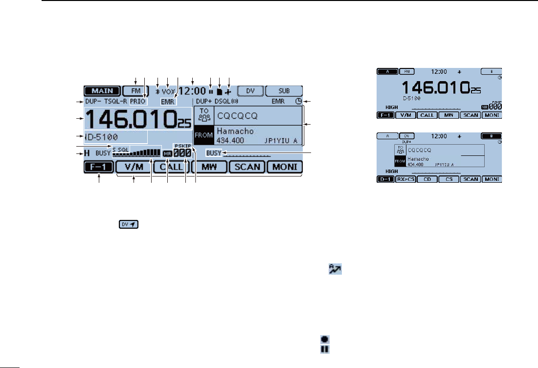
e MODE ICONS
Displays the selected operating mode. (p. ??-??)
• In the DV mode, “ ” is displayed when you set the GPS TX
Mode to “D-PRS” or “NMEA.” (p. ??-??)
r PRIORITY ICON
Displayed when priority scan is turned ON. (p. ??-??)
tBluetoothICON (p. ?-?)
Displayed when you make a Bluetooth® connection be-
tween your transceiver that has the optional UT-133 Blu-
etooth® UNIT installed and a Bluetooth® device.
y VOX ICON (p. ?-?)
Displayed when you make a Bluetooth® connection be-
tween your transceiver that has the optional UT-133 Blu-
etooth® UNIT installed and the optional VS-3 Bluetooth®
HEADSET, and the VOX function is ON.
u EMR/BK/PacketLoss/AutoReplyICON
“ EMR” is displayed when you select the Enhanced ➥Monitor Request (EMR) mode. (p. ?-?)
“ BK” is displayed when you select the Break-in (BK) ➥mode. (p. ?-?)
“ L” is displayed when packet loss has occurred. (p. ?-?) ➥“ ➥” is displayed when you select the Automatic Reply
function. (p. ?-?)
i CLOCK READOUT (p. ?-?)
Displays the current time.
o RECORD ICON (p. ?-?)
Displayed while recording.
• “ ” is displayed while the transceiver is recording.
• “ ” is displayed while the recording is paused.
e r t y u i o !1!0
!2
Dualwatch mode Single watch mode (A band)
Single watch mode (B band)
Controller — Display (Touch screen) (Continued) ■
@5
!3
!4
!9 !5!6!8 !7@0
@1
@2
@3
@4

New2001
4
1
PANEL DESCRIPTION
1
PANEL DESCRIPTION
!0 SD ICON
“ ➥” is displayed when a SD card is inserted.
“ ➥” and “ ” alternately blinks while accessing the SD
card.
!1 GPS ICON
Displays the status of the GPS receiver. (p. ?-?) ➥
“•))” blinks when the GPS alarm beeps. (p. ?-?) ➥
!2 AUTO POWER OFF ICON (p. ??-??)
Displayed when the Auto power OFF function is ON.
!3 DR SCREEN (p. ??-??)
Displays the DR screen where the D-STAR settings are made.
!4BUSY/MUTEICON (p. ??-??)
“BUSY” is displayed while a signal is being received or ➥the squelch is open.
“BUSY” blinks while the monitor function is activated. ➥ “MUTE” is displayed while the mute is activated. ➥
!5 SKIP ICON (p. ??-??)
Displays the selected Skip function.
• “SKIP”: Memory skip
• “PSKIP”: Program skip
!6MEMORYCHANNELNUMBER
Displays the selected Memory channel number, Mem- ➥ory Bank, and so on. (p. ??-??)
“ WX” is displayed when the Weather channel mode is ➥ON.* (p. ??-??)
*Only the USA version transceiver.
!7 MEMORY ICON (p. ??-??)
Displayed when the Memory mode is selected.
!8 S/RF METER (p. ??-??)
Displays the relative signal strength of the receive signal. ➥
Displays the output power level of the transmit signal. ➥
!9 FUNCTION MENU DISPLAY (p. ??-??)
Displays the touch key, according to the selected function
menu group.
@0 FUNCTION GROUP ICON
Displays the selected function group (F-1 to F-4, D-1 to
D-3) (p. ??-??)
@1 POWER ICONS
Displays the output power level of the transmit signal in ➥three levels. (p. ??-??)
In the Dualwatch mode: ➥
“H” is displayed when you select high power.
“M” is displayed when you select mid power
“L” is displayed when you select low power.
@2S-METERSQUELCH/ATTENUATORICONS(p. ??-??)
“ S SQL” is displayed when the S-meter squelch is ac- ➥tivated.
“ ATT” appears when the Attenuator function is activated. ➥
@3 MEMORY NAME DISPLAY (p. ??-??)
In the Memory mode, displays the programmed memory
name.
@4 FREQUENCY READOUT
Displays the operating frequency. (p. ??-??)
@5 DUPLEX ICON (p. ??-??)
“DUP–” is displayed when minus duplex is selected, and
“DUP+” is displayed when plus duplex is selected.
5
1PANEL DESCRIPTION
New2001 New2001
Controller — Display (Touch screen) (Continued) ■
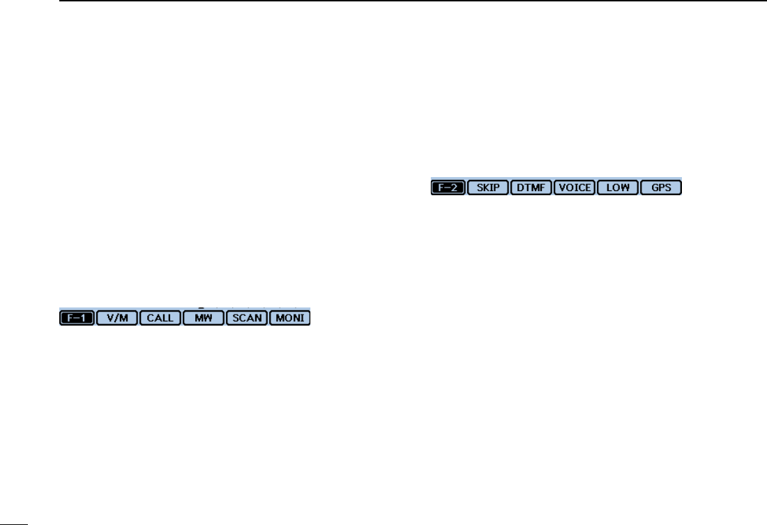
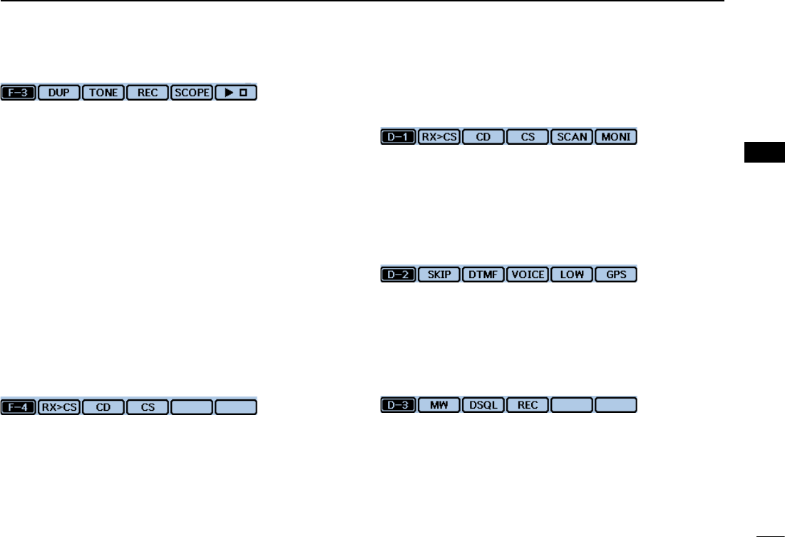
Function menu D
You can toggle the function group to select the desired func-
tion keys to operate the transceiver, depending on the trans-
ceiver’s operating mode or status.
Each function key works for the MAIN band.
• In the VFO, Memory or Call channel mode, you can select
the F-1 to F-4 menus.
• In the DR screen, you can select the D-1 to D-3 menus.
Touch the group icon to toggle the function group. ➥ Touch the group icon for 1 second to display the function ➥menu list.
q w e r t
q [V/M]
Touch to toggle between the VFO and Memory modes.
w [CALL]
Touch to turn the Call channel mode ON or OFF.
e [MW]
Touch to open the Memory Write window. ➥ In the VFO mode or the DR screen, touch for 1 second ➥to store the operating data into the blank channel.
In the Memory or Call channel mode, touch for 1 sec- ➥ond to open the Memory Edit screen.
r [SCAN]
Touch to open the Scan type setting window. ➥ Touch for 1 second to start the last used scan. ➥
t [MONI]
Touch to turn the Monitor function ON or OFF.
u i o !0y
y [SKIP]
(Appears in the Memory mode.)
Touch to open the Scan Skip setting window.
u [DTMF]
Touch to open the DTMF send window.
i [VOICE]
( Displayed only when you insert an SD card into the trans-
ceiver’s SD card slot.)
Touch to open the “VOICE TX” screen.
o [LOW]
Touch to open the TX power setting window.
!0 [GPS]
Touch to open the GPS item setting window.
New2001
6
1
PANEL DESCRIPTION
1
PANEL DESCRIPTION
!2 !3 !4 !5!1
!1 [DUP]
Touch to open the duplex direction setting window.
!2 [TONE]
(Displayed only when in the FM/FM-N mode.)
Touch to open a Tone function setting window.
!3 [REC]
( Displayed only when you insert an SD card into the trans-
ceiver’s SD card slot.)
Touch to start recording a QSO (communication) audio.
!4 [SCOPE]
Touch to open the sweep item setting window.
!5 [≈]
( Displayed only when you select “Continuous Sweep” in
[SCOPE](!4).)
Touch to start or stop a continuous sweeping.
!7 !8!6
(Displayed only when in the DV mode.)
!6 [RX>CS]
Touch to open the “RX>CS” screen. ➥ Touch for 1 second to set the received station call sign ➥as the destination (UR) call sign.
!7 [CD]
Touch to open the “RX HISTORY” screen.
!8 [CS]
Touch to open the “CALL SIGN” screen.
!7 !8 !9 @0!6
!9 [SCAN]
Touch to open the DR scan setting window. ➥ Touch for 1 second to start the last used scan. ➥
@0 [MONI]
Touch to turn the Digital Monitor function ON or OFF.
u i o !0@1
@1 [SKIP]
Touch to open the skip setting window for the Access ➥repeater scan.
Touch for 1 second to set the skip setting in the Func- ➥tion menu.
@2 !3e
@2 [DSQL]
(Appears in the DV mode.)
Touch to open the Digital squelch function setting window.
If you set the operating mode to “DV” in the VFO mode,
[DSQL] is displayed instead of [TONE] on the F-3 menu.
7
1PANEL DESCRIPTION
New2001 New2001
q w e r t y u i
o
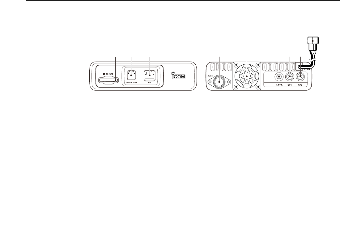
Main unit — Front and rear panels ■
q SD CARD SLOT [SD CARD]
Insert an SD card (purchase separately). (p. ??-??)
w CONTROLLER CONNECTOR [CONTROLLER]
Connects to the Controller using the supplied control cable.
e MICROPHONE CONNECTOR [MIC]
Plug in the supplied microphone (HM-207) or the optional
microphone (HM-154).
r ANTENNA CONNECTOR
Connect a 50 ø impedance of antenna with a PL-259 con-
nector.
The transceiver has a built-in duplexer, so you can use a
144 and 430 MHz dual-band antenna without needing an
external duplexer.
t COOLING FAN
The cooling fan for heat dissipation.
You can select the Fan control option in the Menu screen,
and automatically starts to rotate when you begin transmit-
ting, or continuously rotates from power ON.
y DATA JACK [DATA]
Connect a PC through the optional OPC-2218LU DATA
COMMUNICATION CABLE, for cloning or low-speed data com-
munication in the DV mode. (p. ??-??)
uEXTERNALSPEAKERJACK1[SP1]
i EXTERNAL SPEAKER JACK 2 [SP2]
Connect to an 8 ohm external speaker.
• When you connect external speakers to [SP1] and [SP2],
the A band (left side display) audio is heard from [SP1]
and the B band (right side display) audio is heard from
[SP2].
• When you connect an external speaker to [SP1], the A
and B band audio is heard from [SP1]. In this case, the
internal speaker is disabled.
• When you connect an external speaker to [SP2], the
A band (left side display) audio is heard from the inter-
nal speaker and the B band (right side display) audio is
heard from the external speaker.
New2001
8
1
PANEL DESCRIPTION
1
PANEL DESCRIPTION
oDCPOWERSOCKET[DC13.8V](p. ??-??)
Connect 13.8 V DC power source through the supplied DC
power cable.
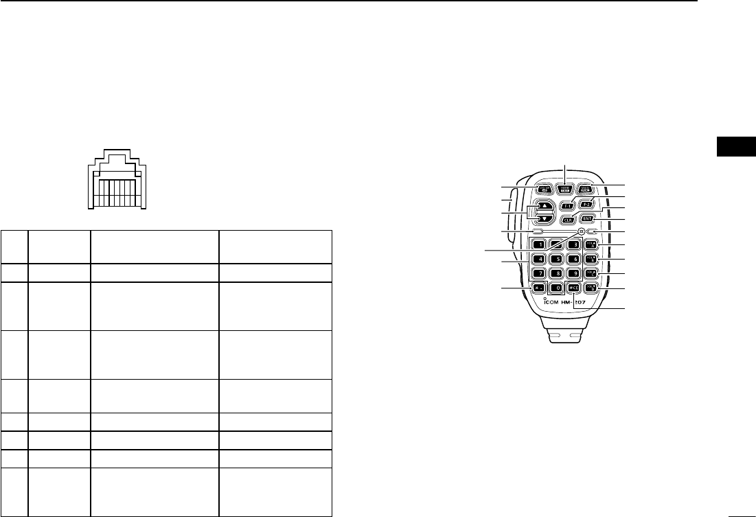
Microphone connector information D
12345678
Front panel view
PIN
No.
NAME DESCRIPTION SPECIFICATIONS
18 V +8 V DC output. Maximum 10 mA
2 MIC U/D Frequency Up/Down UP: Ground
DN: Ground
through 470 ˘
3M8V SW HM-207 connection
Grounds when the
HM-207 is connected. —
4 PTT PTT input Ground for trans-
mission
5 MIC E Microphone ground —
6 MIC Microphone input —
7 GND PTT ground —
8DATA IN
When the HM-207 is
connected, inputs HM-
207 data
—
Microphone(HM-207) ■
With the HM-207, you can input numbers for frequency or
Memory channel setting, and easily adjust the audio volume
or squelch level.
q
w
e
!0
t
y
i
u
o
r
!7
Mic element
!6
!1
!2
!3
!4
!5
qLED1
Lights red while transmitting with [PTT].
w [∫]/[√] (UP/DOWN) KEYS
Push to change the operating frequency or Memory ➥channel.
Hold down to continuously change the frequency or ➥Memory channel.
9
1PANEL DESCRIPTION
New2001 New2001
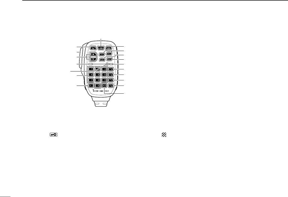
Microphone (HM-207) (Continued) ■
e [PTT] SWITCH
Hold down to transmit, release to receive.
r [VFO/MR•] KEY
Push to toggle between the VFO and Memory modes. ➥(p. ?-?)
Hold down for 1 second to turn the Lock function ON ➥or OFF. (p. ?-?)
t [HOME/CALL] KEY
Push to select the Home channel. ➥ Hold down for 1 second to turn the Call channel mode ➥ON or OFF.
y [MAIN/DUAL] KEY
In the Single watch mode, push to toggle between the ➥A and B bands.
In the Dualwatch mode, push to toggle between the ➥MAIN and SUB bands.
Hold down for 1 second to toggle between the Dual- ➥watch and Single watch modes.
u[F-1]KEY
Push to activate the preprogrammed function of the [F-1]
key.
(Default: During RX/Standby: [BAND/BANK]
During TX: [T-CALL])
[F-2]KEY
Push to activate the preprogrammed function of the [F-2]
key.
(Default: During RX/Standby: [Monitor]
During TX: [---])
You can assign a desired function in the Menu screen.
i [CLR] KEY
In the Menu screen or Quick Menu window, push to return
to the standby screen.
p [ENT] KEY
In the VFO mode, push to open the frequency entry ➥window.
In the Memory mode, push to open the memory chan- ➥nel number input window.
After the numeral input, push to set. ➥
q
w
e
!0
t
y
i
u
o
r
!7
Mic element
!6
!1
!2
!3
!4
!5

New2001
10
1
PANEL DESCRIPTION
1
PANEL DESCRIPTION
!0 LED 2
Lights green when transceiver’s power is ON.
!1 [VOL∫/A] KEY
Push to increase the audio output level. ➥When entering a DTMF code, push to input ‘A.’ ➥
!2 [VOL√/B]KEY
Push to decrease the audio output level. ➥When entering a DTMF code, push to input ‘B.’ ➥
!3 [SQL∫/C] KEY
Push to increase the squelch level. ➥When entering a DTMF code, push to input ‘C.’ ➥
!4 [SQL√/D] KEY
Push to decrease the squelch level. ➥When entering a DTMF code, push to input ‘D.’ ➥
!5 [#/CE] KEY
In the frequency entry screen, push to delete a num- ➥ber.
When entering a DTMF code, push to input ‘#.’ ➥
!6 [M/.] KEY
In the frequency entry screen, push to input a ‘.’ (deci- ➥mal point).
When entering a DTMF code, push to input ‘ ➥M.’
!7[0]to[9]KEYS
In the frequency entry window or while entering a DTMF
code, push to input ‘0’ through ‘9.’
Setting frequency and Memory channel D
[Example for frequency setting]
First, push [VFO/MR• ] to select the VFO mode.
Toenterthe435.680MHzfrequency:
Push [4], [3], [5], [6], [8], [0], then [ENT]. ➥
Tochangethe439.680MHzto439.540MHz:
Push [•], [5], [4], [0], then [ENT]. ➥
Toenterthe433.000MHzfrequency:
Push [4], [3], [3], then [ENT]. ➥
[Example for Memory channel setting]
First, push [VFO/MR• ] to select the Memory mode.
To select the Memory channel ‘5’:
Push [5] then [ENT]. ➥
New2001New2001
11
New2001
BASICOPERATION
2
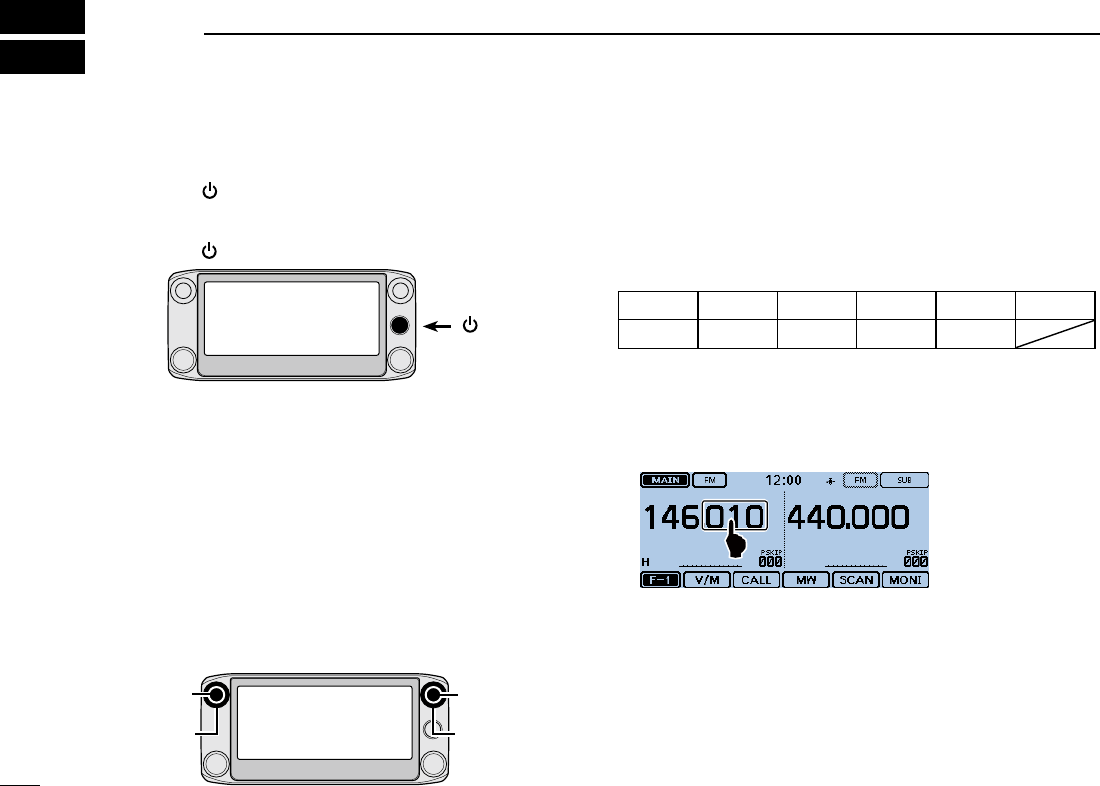
Power ON the power ■
Hold down [ ➥] for 1 second to turn ON the power.
• A beep sounds and, after “ICOM ID-5100” and power source
voltage are displayed, the operating frequency appears.
• Hold down [ ] for 1 second to turn OFF the power.
[ ]
Setting audio volume and ■squelch level
Rotate [VOL] to adjust the audio level. q Rotate [SQL] until the noise and the “BUSY” icon just dis- wappear.
• Rotating [SQL] counterclockwise makes the squelch tight. The
tight squelch is for strong signals.
• When rotating [SQL] clockwise beyond the center position,
[SQL] can be used as ‘S-meter Squelch’ or ‘Attenuator.’ Select
the [SQL] option in the Menu screen. (p. ??-??)
[VOL]
[SQL]
[VOL]
[SQL]
Selecting a tuning step ■
Rotating [DIAL] changes the frequency in the selected tuning
steps.
The VFO scan uses this step to search for a signal.
Tuning steps (kHz)
5 6.25 8.33* 10 12.5 15
20 25 30 50 Auto*
*Appears only when the AIR band is selected.
Tuning step selection DTouch the kHz digits for 1 second. q
• Opens the Tuning step setting window.
Touch the desired tuning step. w
• Sets the tuning step, and then returns to the previous screen.
• You can set the tuning step for both the VFO and Memory
mode.
• You can set the tuning step for each band.
• In the Tuning step setting window, rotating [DIAL] also selects
the tuning step.
New2001
12
2
BASIC OPERATION
New2001
2
BASIC OPERATION
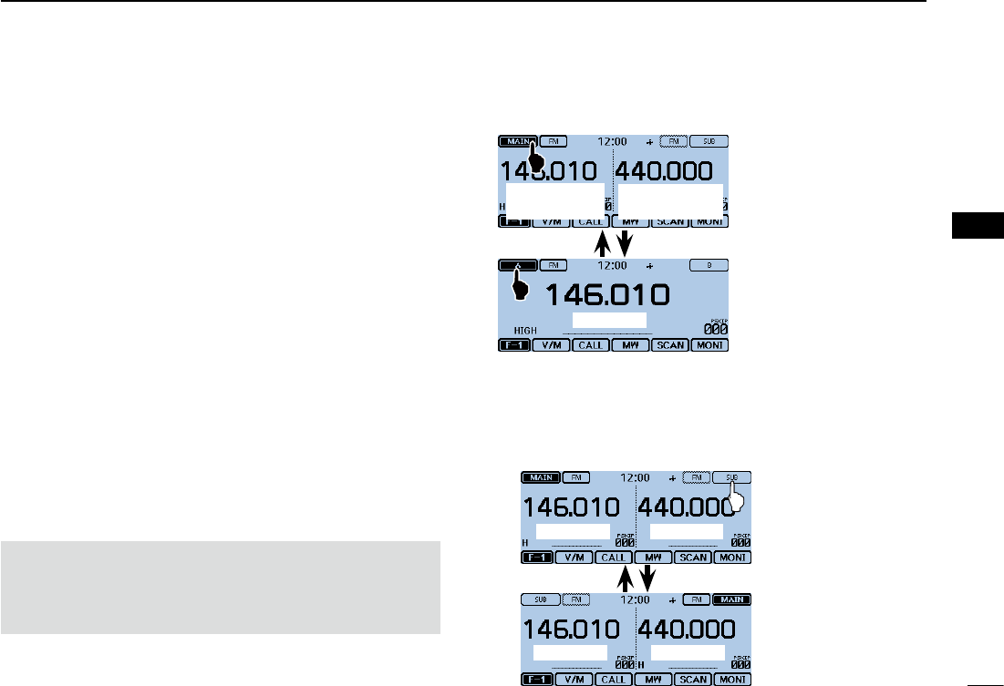
Selecting the watch mode ■
The transceiver has two independent watch modes: Dual-
watch mode and Single watch mode.
Dualwatch mode
The Dualwatch mode uses the MAIN and SUB bands, and
you can simultaneously monitor both bands.
In the Dualwatch mode, both MAIN and SUB bands are dis-
played side by side.
Touching [MAIN] or [SUB] for 1 second selects the Single
watch mode.
Single watch mode
The Single watch mode uses the A and B bands, instead of
the MAIN and SUB bands, and you can monitor one of them
at a time.
In the Single watch mode, only one of the A or B bands is
displayed.
Touching [A] or [B] for 1 second selects the Dualwatch
mode.
NOTE: The Dualwatch left side band becomes the A band
in the Single watch mode.
The Dualwatch right side band becomes the B band in the
Single watch mode.
SelectingtheMAINorSUBband D Touch [SUB] to toggle the displayed band between the ➥MAIN band and the SUB band.
• [MAIN] will be highlighted to indicate the MAIN band.
In Single watch
mode: A band
A band
In Single watch
mode:Bband
Dualwatch mode
Single watch mode
MAIN band SUBband
MAIN bandSUBband
13
2BASIC OPERATION
New2001 New2001
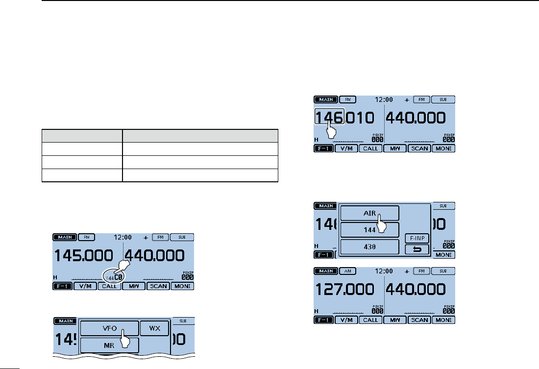
Selecting the operating band ■
The transceiver can receive the AIR, 144 MHz or 430 MHz
bands.
The frequency range on each operating band is shown to the
right.
You can transmit on only the 144 MHz and 430 MHz bands.
Operating band Frequency range
AIR 108.000 MHz to 137.000 MHz
144 MHz 137.000 MHz to 174.000 MHz
430 MHz 380.000 MHz to 479.000 MHz
Operating band setting DTouch the Memory channel number. q
• Opens the Mode setting window.
Touch [VFO]. w
• Selects the VFO mode.
Touch the MHz digits. e
• Opens the operating band setting window.
Touch the desired operating band. r
• The operating band setting window disappears.
• Touch [F-INP] to open the frequency entry window. You
can directly enter a frequency.
New2001
14
2
BASIC OPERATION
2
BASIC OPERATION
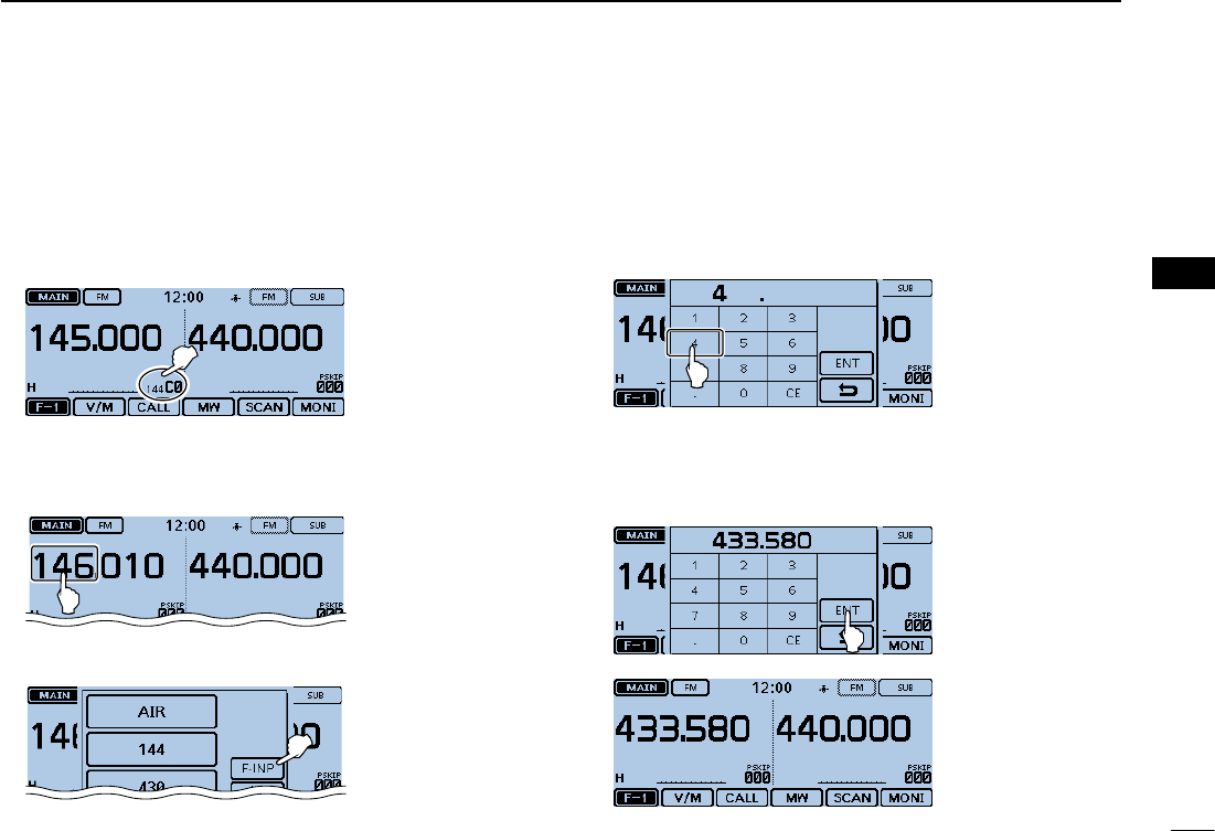
Direct frequency input ■
You can directly enter a frequency in the frequency entry win-
dow.
Touch the Memory channel number. q
• Opens the Mode setting window.
Touch [VFO]. w
• Selects the VFO mode.
Touch the MHz digits. e
• Opens the operating band setting window.
Touch [F-INP]. r
• Opens the frequency entry window.
Touch the numbers to enter the desired frequency. t
• The rst entered digit is displayed to the left. Then the next
entered digit is displayed to the right of the previously entered
digit.
• If desired, touch “CE” to delete the entry.
Touch [ENT] to set the frequency. y
• Closes the frequency entry window.
• If you touch [ENT] without entering a digit below 100 kHz,
all unentered digits are set to “0.”
The entered frequency is displayed.
15
2BASIC OPERATION
New2001 New2001
Selecting the Mode and the DR function ■
VFO/Memory/Call channel/Weather channel* mode D
VFO mode
The VFO mode is used to set the operating frequency.
Memory mode
The Memory mode is used to operate on Memory channels.
Call channel mode
The Call channel mode is used to operate on the most-often
used frequencies.
Weather channel mode*
The Weather channel mode is used to monitor weather chan-
nels from the NOAA (National Oceanographic and Atmo-
spheric Administration) broadcasts.
*Selectable in only the U.S.A. version transceivers.
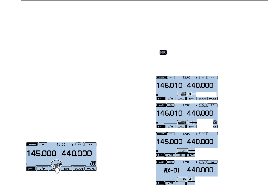
Touch the Memory channel number. q
• Opens the Mode setting window.
Select the desired Mode. w
Rotate [DIAL] to select the operating frequency or a channel. e
• “ ” and the selected Memory channel number are displayed.
• A selected Call channel number (“144 C0,” “144 C1,” “430 C0” or
“430 C1”) is displayed.
• The selected weather channel number (“WX-01” to “WX-10”) is
displayed.
Call channel
mode
VFO mode
Memory
mode
Weather channel
mode*
New2001
16
2
BASIC OPERATION
2
BASIC OPERATION
DR(D-STARRepeater)functionselection D
The DR (D-STAR Repeater) function is for D-STAR repeater
operation. In this mode, you can easily select the prepro-
grammed repeaters and UR call signs by rotating [DIAL].
See page ??-?? for the DR function details.
Touch [DR]. q
• Displays the DR screen.
[DR]
Rotate [DIAL] to select a desired access repeater. w
DR screen
Touch [DR]. e
• Closes the DR screen.
Transmitting ■
Transmitting on an Amateur band D
Before transmitting, monitor the operating frequency
to make sure transmitting won’t cause interference to
other stations on the same frequency.
CAUTION: Transmitting without an antenna may damage
the transceiver.
You can transmit on only the 144 MHz and 430 MHz
bands.
Set the operating frequency. (p. ?-?) qTouch the Power icon. w
• Opens the output power level setting window.
Touch the transmit output power level. e
• Select a level to suit your operating requirements.
• In the Dualwatch mode, “H” indicates high power, “M” in-
dicates mid power and “L” indicates low power.
Hold down [PTT] to transmit, and speak at your normal rvoice level.
• The transmit LED lights red while transmitting.
• The S/RF meter displays the output power level.
Release [PTT] to receive. t
17
2BASIC OPERATION
New2001 New2001
Selecting the operating mode ■
Operating modes are determined by the modulation of the
radio signals. The transceiver has a total of five operating
modes, AM, AM-N, FM, FM-N and DV.
The FM mode is set as a default.
Touch the Mode icon. q
• Opens the operating mode setting window.
Touch a desired operating mode. w
• You can select the AM or AM-N mode for only the AIR band
(108.000 MHz to 136.995 MHz).
• You can select the FM, FM-N or DV mode for only the 144 and
430 MHz bands.
• While in the FM-N mode, the TX modulation is automatically set
to narrow (approximately ±2.5 kHz)
• While in the DV mode, [GPS] appears in the operating mode
setting window, and you can select the GPS TX mode. When the
GPS TX mode is set, “ ” is displayed. (p. 8-??)
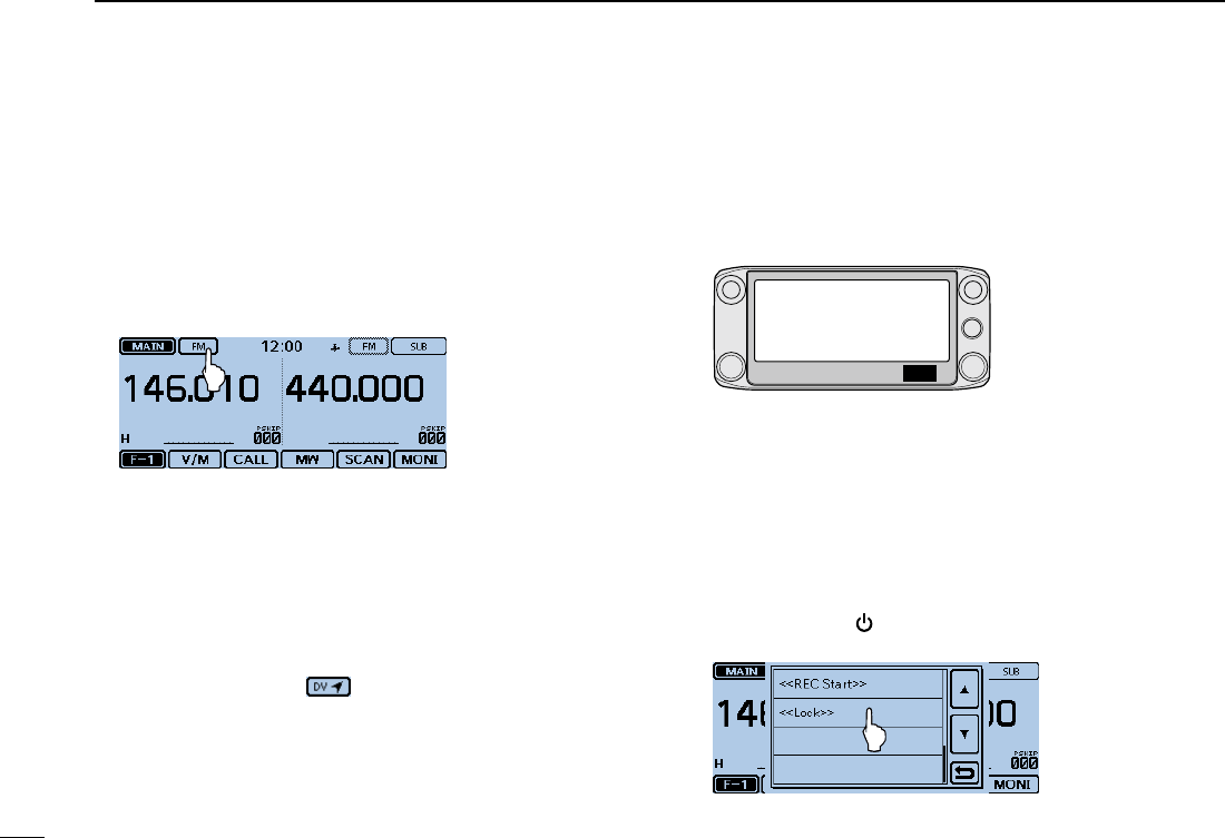
Lock function ■
You can use the Lock function to prevent accidental frequen-
cy changes and unnecessary function access.
Touch [QUICK]. q
[QUICK]
Touch “<<Lock>>”. w
• If the item is not displayed, touch [∫] or [√] one or more times to
select another page.
• When the Lock function is turned ON and the locked key is
pushed, the touch screen is touched, or [DIAL] is rotated, the
“LOCK” dialog box appears.
• To turn OFF the Lock function, touch [OFF] in the “LOCK” dialog
box.
• You can still use [ ], [PTT], [SQL] and [VOL] while the Lock func-
tion is ON.
Quick Menu window
New2001
18
2
BASIC OPERATION
2
BASIC OPERATION
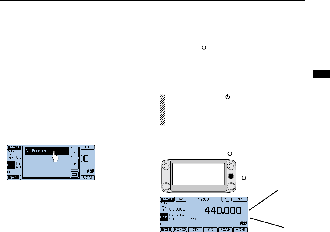
Home channel function ■
Home channels are often-used frequencies you can preset in
the transceiver’s VFO mode, Memory mode and DR function.
Select the Home channel function by just touching [HOME]
in each mode.
Home channel setting D Select the desired mode or the DR screen to set the Home qchannel.
Select a frequency to be set as the Home channel. w
• While in the DR screen, select “FROM.”
Touch [HOME] for 1 second. eTouch the displayed item to set the Home channel. r
• While in the VFO mode, touch “Set Frequency,” while in the
Memory mode, touch “Set Channel.” or while in the DR screen,
touch “Set Repeater.”
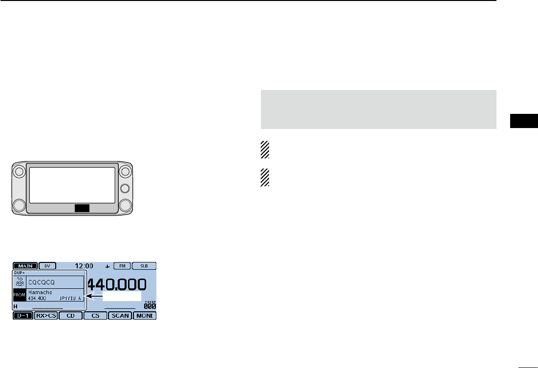
Speech function ■
When you push [ ](SPEECH), the Speech function audibly
announces the displayed frequency and operating mode in
the VFO, Memory or Call channel modes, or the call sign of
the DR function.
Also, you can use other speech functions, such as the [DIAL]
speech function and Mode speech function. (pp. ??-??, ??-
??)
NOTE: When you push [ ](SPEECH) while recording the
received audio in the DV mode, the received audio will be
muted, and no audio is recorded onto the SD card.
In modes other than the DV mode, the received audio will
be recorded.
You set the detail settings of the Speech function in the
“SPEECH” item of the Menu screen. (p. ?? to ??)
Example: When pushing [ ](SPEECH).
[ ](SPEECH)
JP1YIU A
New2001
19
New2001New2001
MEMORY MANAGEMENT
3
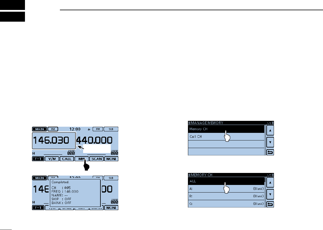
Writing a Memory channel ■
The Memory mode is useful to quickly select often-used re-
peaters.
In this section, the basic channel programming is described.
See the Full Instructions for details.
Example: Writing 146.030 MHz/FM mode into a blank chan-
nel.
Touch the Function group icon one or more times. q
• Selects the F-1 menu.
Touch [MW] for 1 second. w
• The memory contents are briey displayed, and then the operat-
ing data are saved into a blank channel.
Stored data
Checking the programmed ■Memory contents
The programmed Memory channels can be checked on the
“MEMORY LIST” screen.
Example: Checking the contents of the Memory channel ‘5.’
Touch [MENU]. q Touch “Memory CH.” w
(Manage Memory > Memory CH)
• If the item is not displayed, touch [∫] or [√] one or more times to
select the page.
Touch “ALL.” e
• Displays the “MEMORY CH ALL” screen.
20
3
MEMORY OPERATION
New2001
3
MEMORY OPERATION
New2001
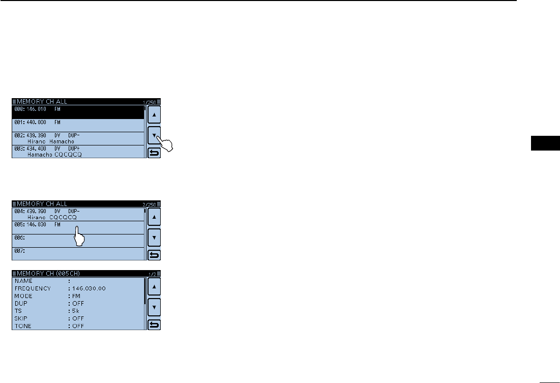
Touch [ r∫] or [√].
• Displays Channel 5.
Touch “005.” t
• Displays the programmed data in Channel 5.
• Touch [∫] or [√] one or more times to select the page.
Touch [MENU]. y
• Closes the “MEMORY CH ALL” screen.
New2001
21
New2001New2001
D-STAROPERATION
4
UniquefeaturesofD-STAR ■
Easy Cross band operation ●
Easy call sign entry with the Re- ●
peater list or TX/RX History
Call Sign Capture key ●[RX>CS]
makes call sign capture easy.
1200 MHz 430 MHz
You can communicate with
a 1200 MHz D-STAR station
using the ID-5100!
Easy Destination
(To) setting!
This key makes call
sign capture easy!
22
4
D-STAR OPERATION
New2001
4
D-STAR OPERATION
New2001
D-STARIntroduction ■
• In the original D-STAR (Digital Smart Technologies for
Amateur Radio) plan, JARL envisioned a system of
repeaters grouped together into Zones.
• The D-STAR repeater enables you to call a HAM sta-
tion near you, or around the world.
• You can transmit and receive digital voice, including
low-speed data, at the same time. You can transmit
and receive position data from the built-in GPS re-
ceiver.
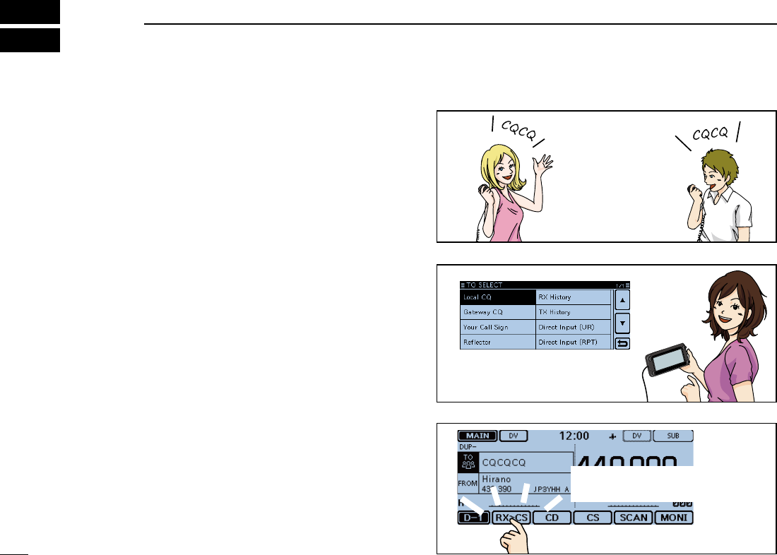
You can easily use the D-STAR repeaters with the DR (D-
STAR Repeater) function. With this function, you can select
the preprogrammed repeater or frequency in “FROM” (the ac-
cess repeater or simplex), and UR call sign in “TO” (destina-
tion), as shown to the right.
NOTE: If the repeater set in “FROM” (Access Repeater)
has no Gateway call sign, you cannot make a gateway
call.
Destination
(Repeater/Station)
Access repeater
or Simplex
In the DR screen
IMPORTANT!
Before starting D-STAR, the following steps are needed.
STEP 1 Entering your call sign (MY) into the transceiver. STEP 2 Registering your call sign (MY) to a
gateway repeater. STEP 3 Entering your D-STAR equipment into your registration form. You have
completed the steps!!
See page 6-?? for details.
AbouttheDR(D-STARRepeater)function ■
23
4D-STAR OPERATION
New2001 New2001
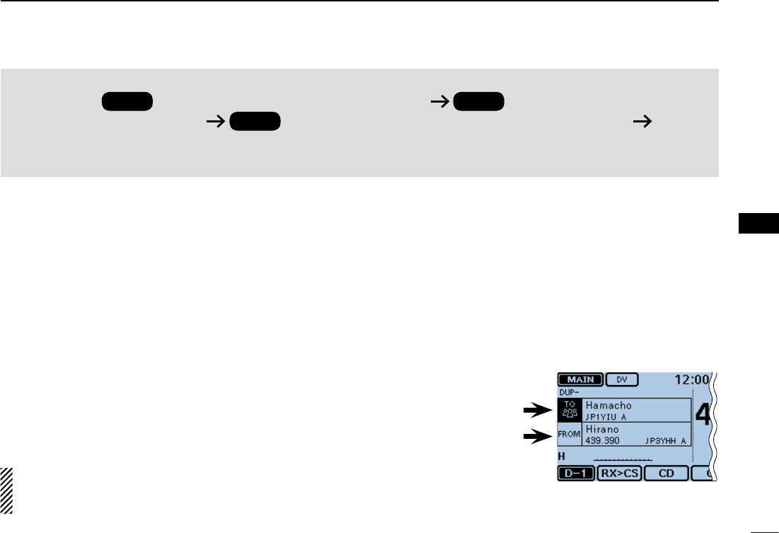
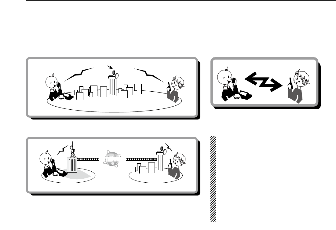
Way to communicate with the DR function ■
With the DR function, the transceiver has three ways to communicate, as shown below.
NOTE:
• Using the repeater list is required to use the DR
function. (pp. ??-?? to ??-??)
• Before operating in the duplex mode, be sure to
check whether the repeater is busy, or not. If the
repeater is busy, wait until it is clear, or ask for a
“break” using a method acceptable to your local
procedures.
• The transceiver has a Time-Out Timer function
for DV operation. The timer limits a continuous
transmission. Warning beeps will sound approx-
imately 30 seconds before time-out and then
again immediately before time-out.
INTERNET
Local area call Access repeater
Hamacho
repeater
Hamacho area
INTERNET
Gateway call Hirano
repeater Sapporo
repeater
Hirano area Sapporo area
To call through your local area (access) repeater.
To call through your local area (access) repeater, repeater gateway and
the internet to your destination repeater or individual station’s last used
repeater, using call sign routing.
Simplex call
To call another station not using a repeater.
New2001
24
4
D-STAR OPERATION
4
D-STAR OPERATION
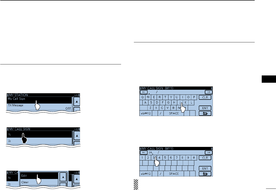
You can enter up to six MY call signs, in [MY1] through [MY6].
Example: Enter “JA3YUA” as your own call sign into the MY
call sign memory [MY1].
Displays the MY Call Sign edit screen1.
Touch [MENU]. qTouch [My Call Sign]. w
(My Station > My Call Sign)
• If the item is not displayed, touch [∫] or [√] one or more times to
select the page.
Touch the MY call sign memory channel “1” ([MY1]) for 1 esecond.
Touch “Edit.” r
• Opens the “MY CALL SIGN (MYM)” edit screen.
The channel number selected in step e is displayed on ‘M.’
• A cursor appears and blinks.
Enter the call sign2.
Touch the desired keypad to select the first digit. t
(Example: J).
• A to Z, 0 to 9, / and (Space) are selectable.
• Touch “ab⇔12” to toggle between the Alphabet input and Num-
ber input modes.
• Touch [CLR] to delete the selected character, symbol or num-
ber.
• Touch “SPACE” to input a space.
Touch [ y] to move the cursor backwards, or touch [] to
move the cursor forwards.
Repeat steps u t and y to enter your call sign of up to 8
characters, including spaces.
(Example: First J, then A, then 3, then Y, then U, then A)
To enter ‘3.’
NOTE: Your call sign must match the call sign you regis-
tered. (p. ??-??)
Enter your call sign into the transceiver ■
25
4D-STAR OPERATION
New2001 New2001
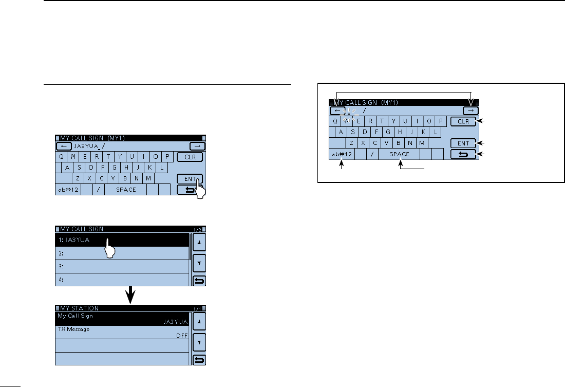
Enter your call sign into the transceiver (Continued) ■
Save the call sign3.
Touch [ENT]. i
• Saves the entered call sign and returns to the “MY CALL
SIGN” screen.
• See “Convenient” below if you want to enter a note.
Touch the entered call sign. o
• Sets the call sign to be used as MY call sign.
!0 Touch [MENU].
• Closes the “MY CALL SIGN” screen.
Moves the cursor
Deletes
Sets
Cancels
Enters a space
Toggles the entry mode
Keys used for entry

New2001
26
4
D-STAR OPERATION
4
D-STAR OPERATION
Convenient! ✓
If desired, enter a note of up to 4 characters, such as the
model of the transceiver, name, area name, and so on, after
your call sign.
Touch [ q] one or more times until the cursor moves to the
right of the “/”.
Repeat steps w t and y on the page ??-?? to enter a 4
character note.
(Example: 5100)
27
4D-STAR OPERATION
New2001 New2001
Register your call sign at a gateway repeater ■
Ifneeded, ask thegateway repeater administrator for
call sign registration instructions.
To use the Internet, you must register your call sign with a
repeater that has a gateway, usually one near your home lo-
cation.
About the registration process described:
This section describes the call sign registration process at
a repeater that is connected to the US Trust server.
There are other systems as well, and they have their own
registration process. For information on how to register on
one of them, contact the administrator of a repeater that
uses the alternate system.
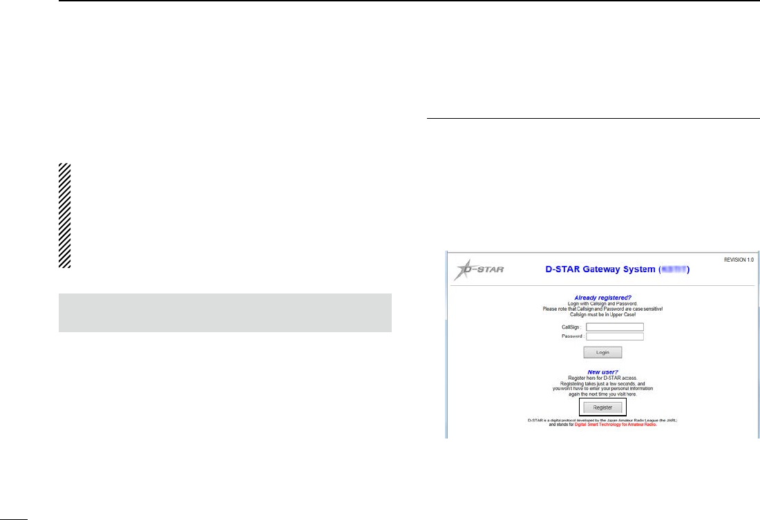
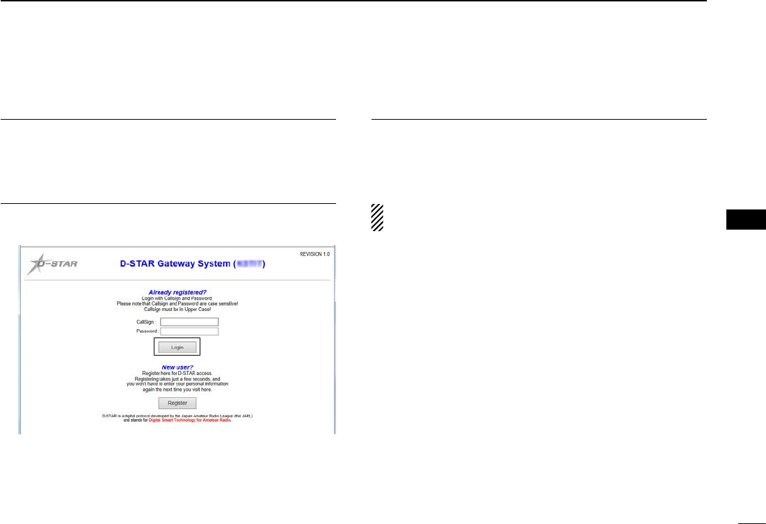
Access the call sign registration screen1.
Access the following URL to find the gateway repeater qclosest to you.
http://www.dstarusers.org/repeaters.php
Click the call sign of the repeater that you want to register wto.
Click the “Gateway Registration URL:” link address. e The “D-STAR Gateway System” screen appears. r
Click [Register] to start the New User registration.
Click
New2001
28
4
D-STAR OPERATION
4
D-STAR OPERATION
Register your call sign2.
Follow the registration instructions found there. t When you receive a notification from the administrator, yyour call sign registration has been approved.
Register your personal information3.
After your registration is approved, log in your personal ac- ucount with your registered call sign and password.
Click
RegisteryourD-Starequipment4.
Register your D-STAR equipment information. i
Ask the gateway repeater administrator for details.
When your registration is complete, log out of your per- osonal account, and start using the D-STAR network.
NOTE: You must register your D-STAR equipment BE-
FORE you can make calls through the gateway.
29
4D-STAR OPERATION
New2001 New2001
Making a Simplex call ■
You can make a transceiver to transceiver call (through no
repeater) in the DR screen.
NOTE: Depending on the transceiver's version, the fre-
quencies may be different. Check for acceptable frequen-
cies for your operating area.
✓What is a Simplex Call??
A simplex call is a direct call to another station, not using a
repeater.
Example: Making a simplex call on 433.450 MHz.
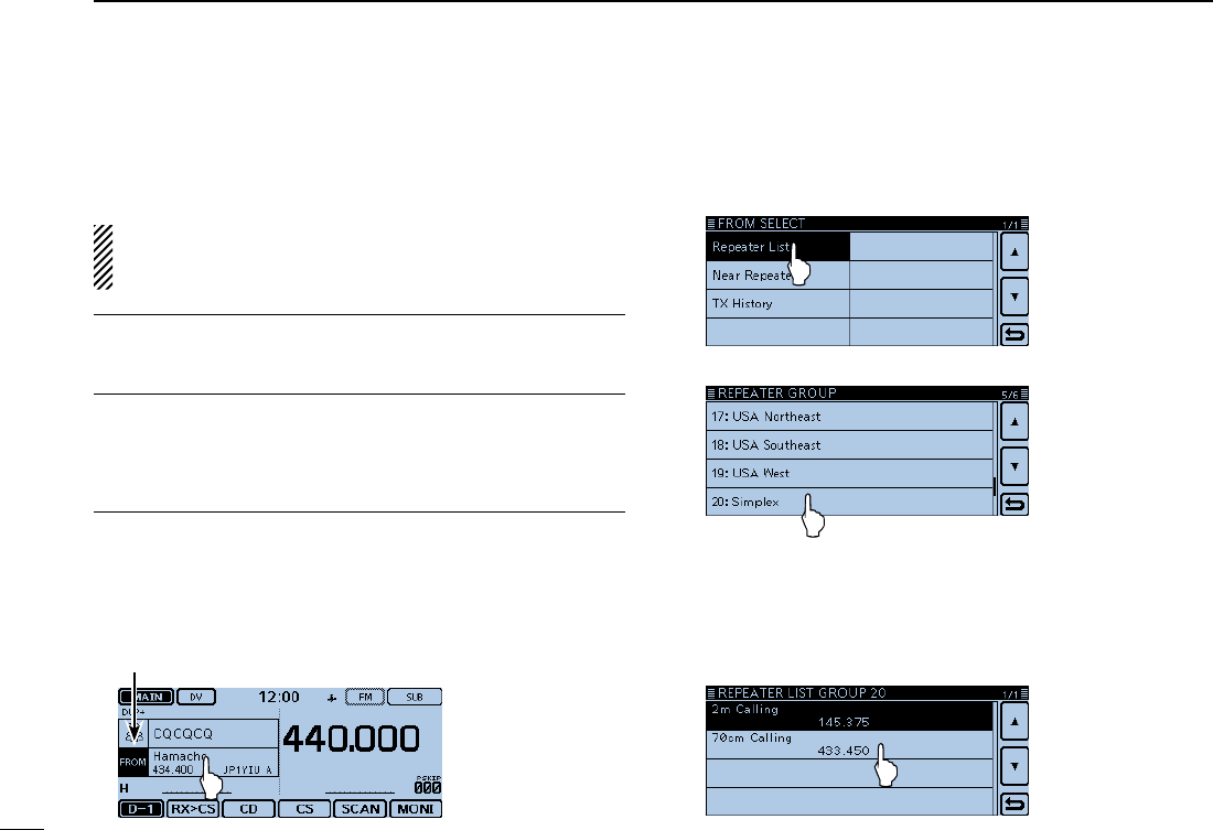
“FROM” (Simplex channel) setting1.
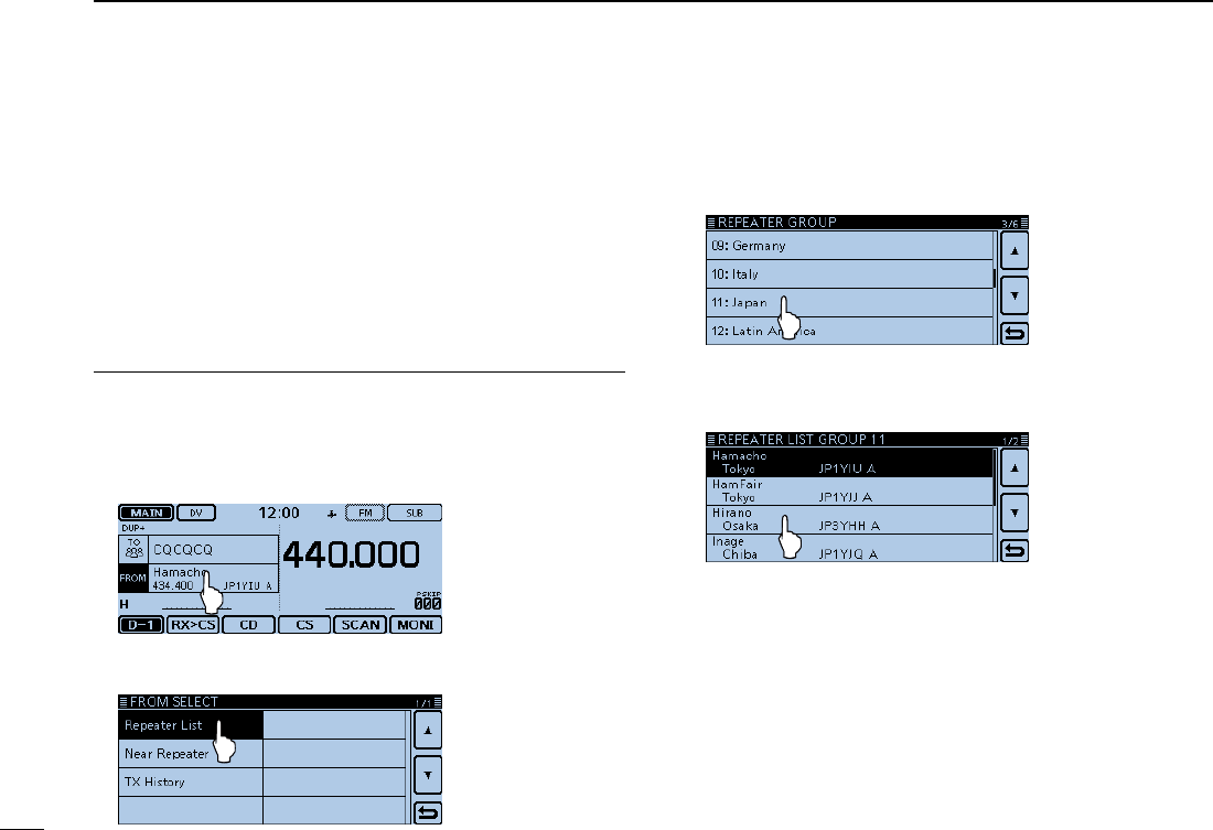
Touch [DR]. qCheck whether or not “FROM” is selected. w
• If “FROM” is not selected, touch the “FROM” eld.
Touch the “FROM” field. e
• Opens the “FROM SELECT” screen.
“FROM” is selected.
Touch “Repeater List.” r
• Opens the “REPEATER GROUP” screen.
Touch “Simplex.” t
Touch a desired frequency. (Example: 433.450) y
• Returns to the DR screen, and the selected frequency is dis-
played in “FROM.”
• “CQCQCQ” is displayed in “TO.”
- If a station call sign is set in “TO,” select “Local CQ” in the “TO
SELECT” screen to set “CQCQCQ” in “TO.”
New2001
30
4
D-STAR OPERATION
4
D-STAR OPERATION
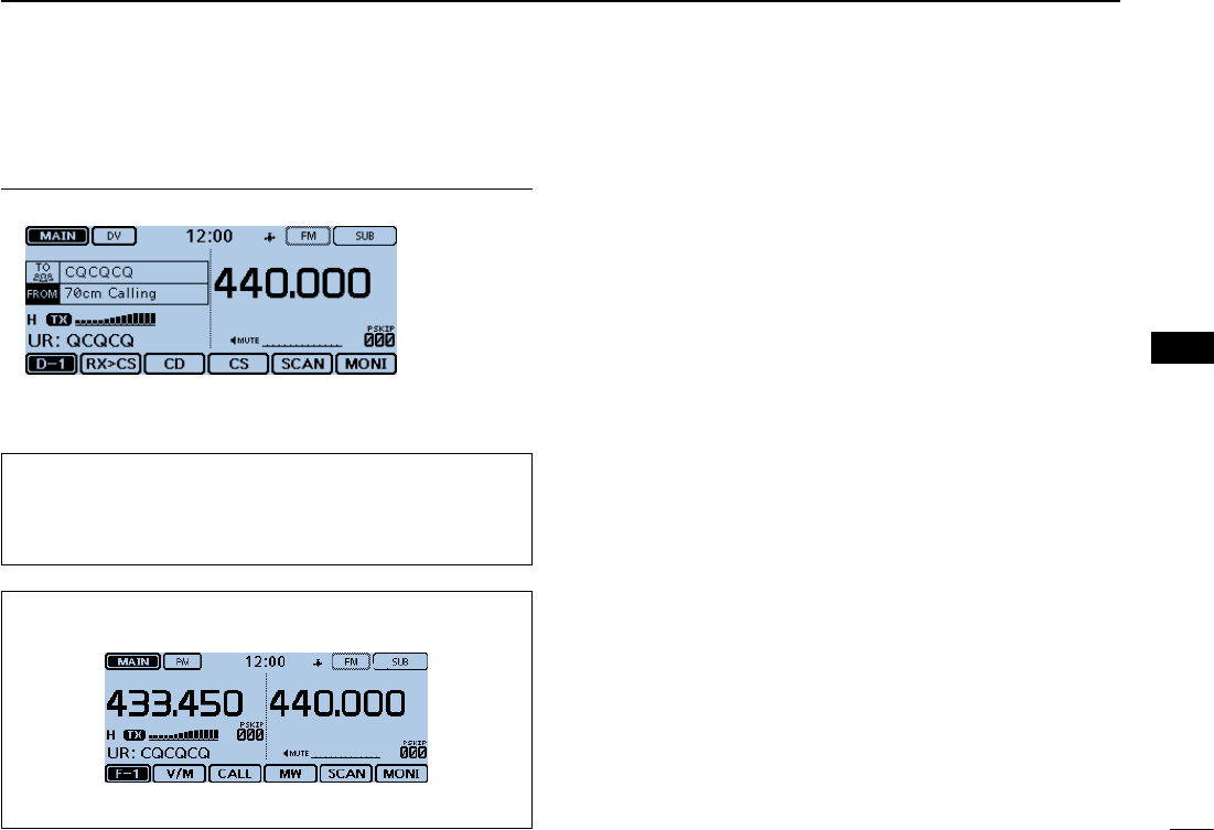
Hold down [PTT] to transmit2.
• The LED1 on the microphone lights red.
When you make a simplex call in the VFO mode, the LCD
changes, as shown below.
While transmitting in the DV mode
For your reference:
The simplex frequencies can be changed in the MENU
screen.
( DV memory > Repeater List > Repeater group > Simplex)
31
4D-STAR OPERATION
New2001 New2001
Accessing repeaters ■
This section describes how to check whether or not you can
access your local area repeater (Access repeater), and if your
signal is successfully sent to a destination repeater.
If your call sign (MY) has not been set, or your call sign
and equipment have not been registered at a D-STAR re-
peater, see page ??.
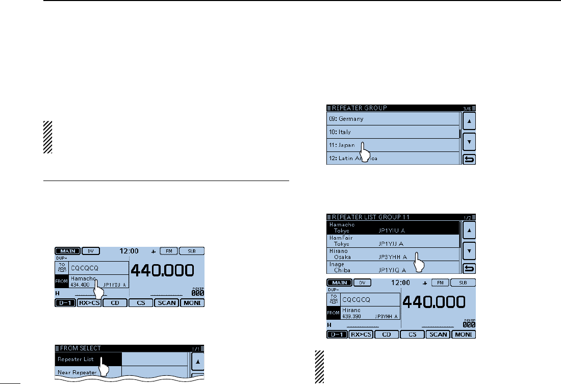
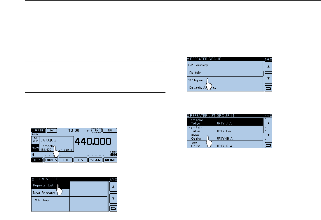
Select your Access repeater (“FROM”)1.
Touch [DR]. qCheck whether or not “FROM” is selected. w
• If “FROM” is not selected, touch the “FROM” eld.
Touch the “FROM” field. e
• Opens the “FROM SELECT” screen.
Touch “Repeater List.” r
• Opens the “REPEATER GROUP” screen.
Touch the repeater group where your access repeater is tlisted. (Example: “11: Japan”)
Touch your access repeater. (Example: “Hirano”) y
• Returns to the DR screen, and the selected repeater name is
displayed in “FROM.”
Even if you select just the repeater name, the repeater call
sign, its frequency, duplex setting, frequency offset and
Gateway call sign are automatically set.
New2001
32
4
D-STAR OPERATION
4
D-STAR OPERATION
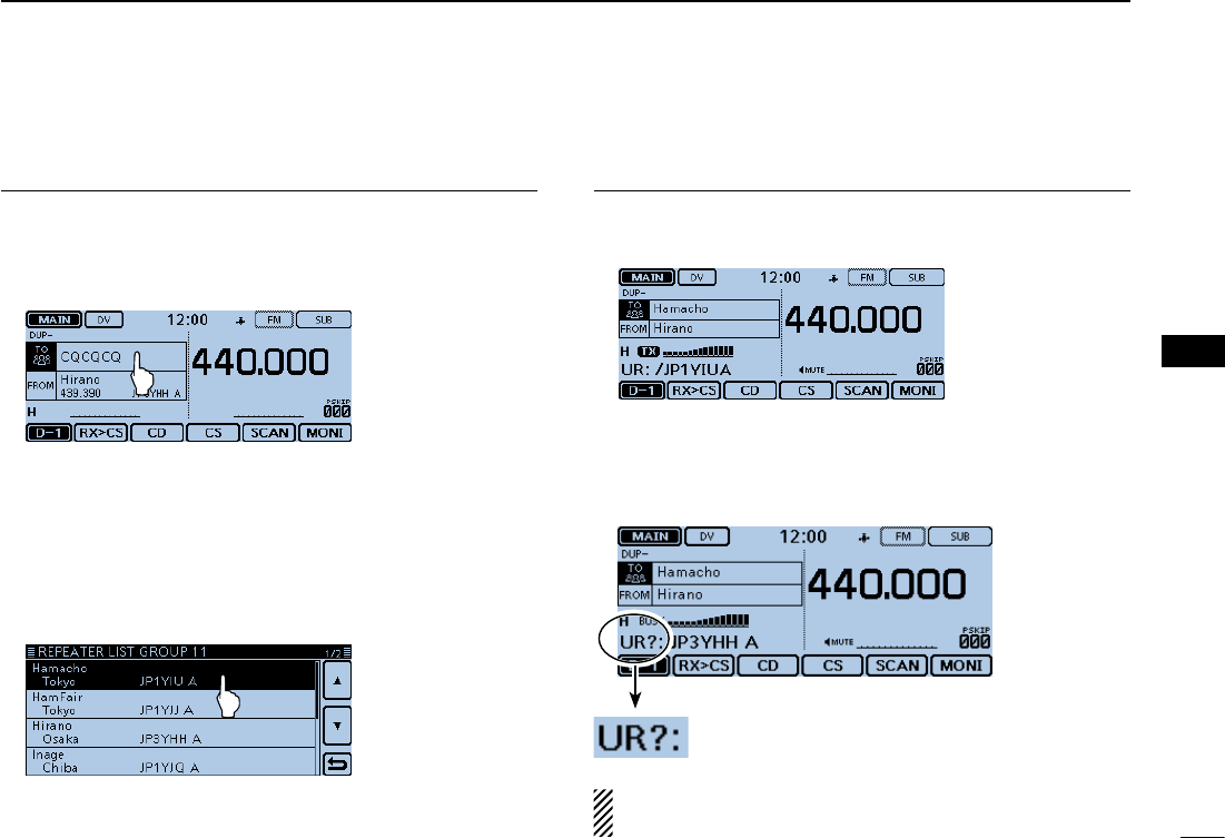
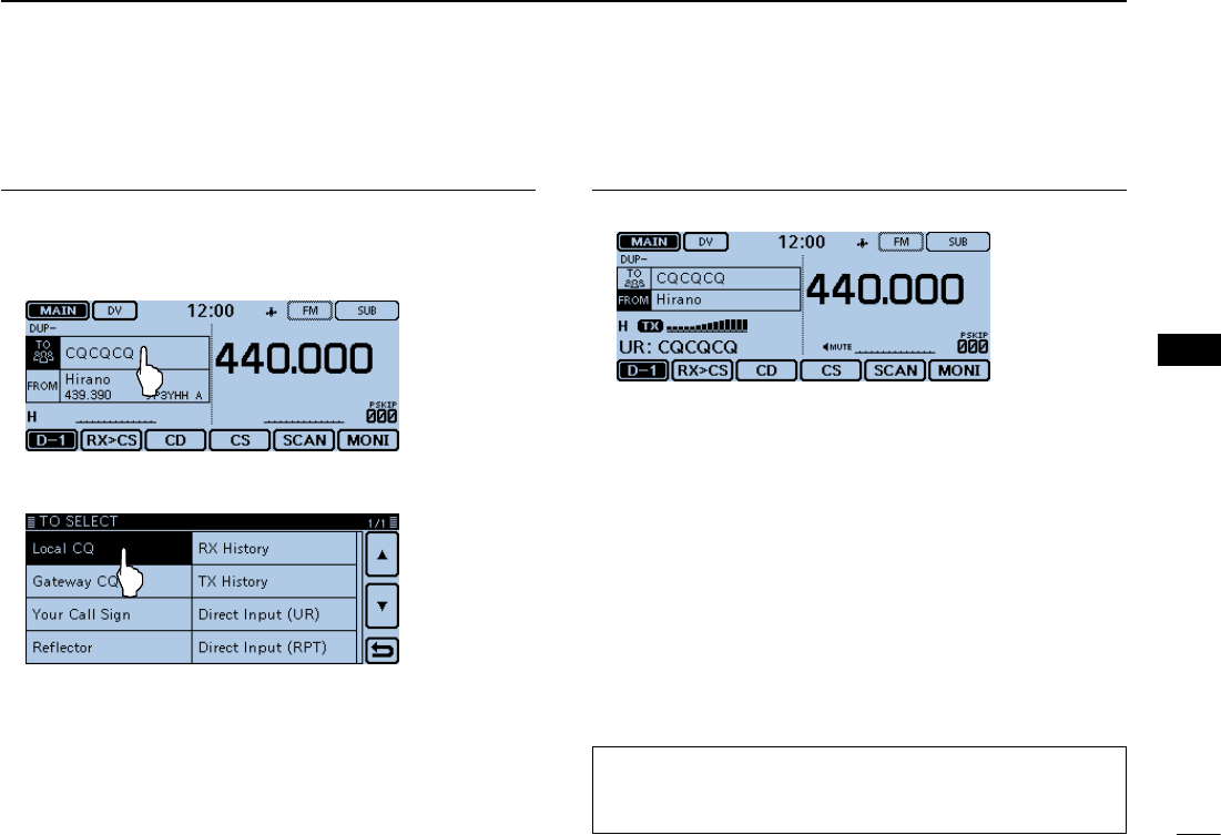
Select the Destination repeater (“TO”)2.
Touch the “TO” field. u
• Check whether “TO” is selected.
Touch the “TO” field again. i
• Opens the “TO SELECT” screen.
Touch “Gateway CQ.” o
• Opens the “REPEATER GROUP” screen.
!0 Touch the repeater group where your destination repeater
is listed. (Example: “11: Japan”)
!1 Touch your destination repeater. (Example: “Hamacho”)
• Returns to the DR screen, and the selected repeater name is
displayed in “TO.”
Check whether you can access the repeater3.
!2 Hold down [PTT] for approximately 1 second to access the
repeater.
!3 If you get a reply call, or “UR?” appears on the LCD within
3 seconds, your signal reached your access repeater and
your call was successfully sent from your destination re-
peater.
Successfully sent!
NOTE: See page ??-?? for status indications after a re-
peater system reply is received.
33
4D-STAR OPERATION
New2001 New2001
Using the RX history ■
When a DV call is received, the call signs of the caller, the
called station and the called station’s access repeater are
stored in the RX history file.
Up to 50 calls can be stored.
This section describes how to view the RX history screen and
how to save the call sign to memory.
The S-meter appears and the caller’s call sign is displayed.
Whenreceivingacallfrom“JM1ZLK.”
To display a received call sign1.
Touch the Function group icon one or more times. q
• Selects the D-1 menu.
Touch [CD]. w
• Opens the “RX HISTORY” screen.
• Touch [∫] or [√] one or more times to select other RX history
memories.
• The rst page of the “RX HISTORY” screen displays the latest
RX record of the MAIN band. The second page or later displays
the record according to the received date and time, regardless
of the band it was received on.
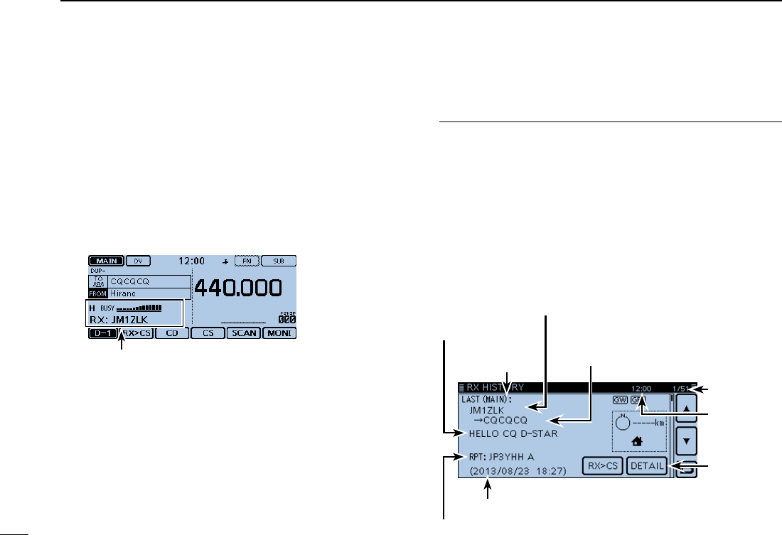
RX HISTORY
record number
RX message
RX HISTORY screen
(LAST (MAIN))
Received date and time
Caller station
( A note may be displayed after “/”.)
Repeater call sign of the called station
Called station
( “CQCQCQ” is displayed if you received
a Local CQ or a Gateway CQ call
Displays the
detail screen
Current time
First page
New2001
34
4
D-STAR OPERATION
4
D-STAR OPERATION
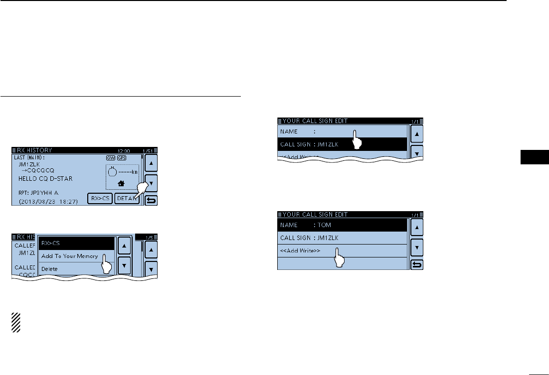
Save the destination call sign into your call sign mem-2. ory from RX History
Touch [ e∫] or [√] one or more times to select the RX HIS-
TORY record with the call sign that you want to save to
memory.
Touch [DETAIL]. r
Touch [QUICK]. tTouch “Add To Your Memory.” y
Touch the call sign that you want to save. u
(Example: “JM1ZLK”)
The display opens the “YOUR CALL SIGN EDIT”
screen, and the call sign is automatically set.
Touch “NAME.” i
• Opens the “NAME” screen.
• Enter a name of up to 16 characters, including spaces.
(Example: TOM)
Touch [ENT]. o
• Returns to the “YOUR CALL SIGN EDIT” screen.
!0 Touch “<<Add Write>>.”
• Opens the “Add write?” window.
!1 Touch [YES].
• Returns to the “RX HISTORY” screen.
35
4D-STAR OPERATION
New2001 New2001
Capturing a call sign ■
After you receive a repeater’s signal, the calling sta-
tion’s call sign can be captured by touching the Call
Sign Capture key ([RX>CS]) for 1 second. Then you can
quickly and easily reply to the call.
What is the Call Sign Capture key?? ✓
Touching the Call Sign Capture key for 1 second sets the last
received station call sign as a temporary destination, and
makes replying quick and easy.
While receiving
When receiv-
ing a call from
“JG3LUK.”
Call Sign Capture key
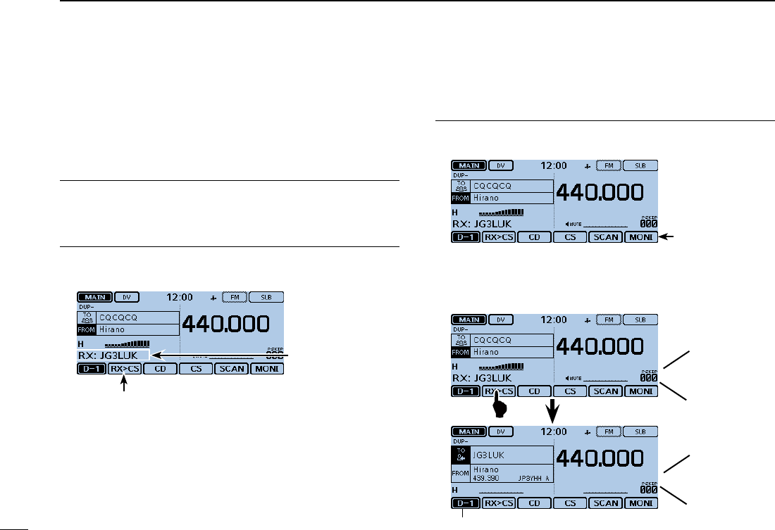
Set the received call sign to the destination1.
Touch the Function group icon one or more times. q
• Selects the D-1 menu.
D-1 menu
Touch [RX>CS] for 1 second. w
• Beep sounds when touched.
• After 1 second, two beeps sound, and the station call sign is an-
nounced.
Blinks after selecting a call sign.
When you touch
[RX>CS].
Beeps
JG3LUK
After1second
Beeps

New2001
36
4
D-STAR OPERATION
4
D-STAR OPERATION
NOTE:
• After touching [RX>CS], you can select another call sign
in the RX history.
• When a received signal is weak, DR scanning or the pow-
er save is ON, the call sign may not be received correctly.
In that case, “--------” appears, an error beep sounds, and
a quick reply call cannot be made.
Hold down [PTT] to transmit2.
• The LED1 on the microphone lights red.
Touch [RX>CS]. e
• Returns to the previous call sign setting.
Returns to the previous screen
37
4D-STAR OPERATION
New2001 New2001
Making a Local area call ■
A Local area call can be made when “Local CQ” is used to set
“CQCQCQ” in “TO” (Destination).
✓What is a Local Area Call??
To call through your local area (access) repeater.
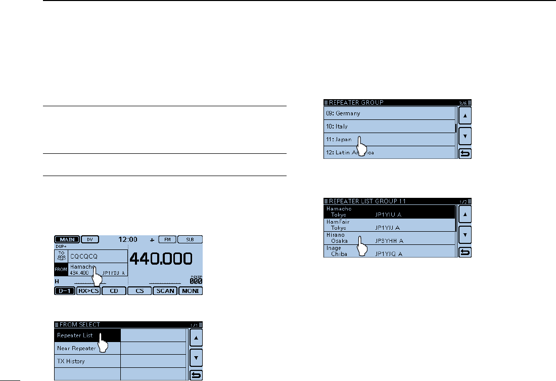
Set “FROM” (Access repeater)1.
Touch [DR]. qCheck whether or not “FROM” is selected. w
• If “FROM” is not selected, touch the “FROM” eld.
Touch the “FROM” field. e
• Opens the “FROM SELECT” screen.
Touch “Repeater List.” r
• Opens the “REPEATER GROUP” screen.
Touch the repeater group where your access repeater is tlisted. (Example: “11: Japan”)
Touch your access repeater. (Example: “Hirano”) y
• Returns to the DR screen, and the selected repeater name is
displayed in “FROM.”
New2001
38
4
D-STAR OPERATION
4
D-STAR OPERATION
Set “TO” (Destination)2.
Touch the “TO” field. u
• Check whether “TO” is selected.
Touch the “TO” field again. i
• Opens the “TO SELECT” screen.
Touch “Local CQ.” o
• Returns to the DR screen, and “CQCQCQ” is displayed in “TO.”
Hold down [PTT] to transmit3.
• The LED1 on the microphone lights red.
For your reference:
The Local CQ call is used to call anyone, but you can call a
specific station by simply saying their call sign.
39
4D-STAR OPERATION
New2001 New2001
Making a Gateway Repeater call ■
A Gateway call can be made when a destination repeater is
selected in “TO” (Destination).
What is a Gateway Repeater Call?? ✓
To call through your local area (access) repeater, repeater
gateway, and the Internet to your desired destination repeat-
er.
Set “FROM” (Access repeater)1.
Touch [DR]. qCheck whether or not “FROM” is selected. w
• If “FROM” is not selected, touch the “FROM” eld.
Touch the “FROM” field. e
• Opens the “FROM SELECT” screen.
Touch “Repeater List.” r
• Opens the “REPEATER GROUP” screen.
Touch the repeater group where your access repeater is tlisted. (Example: “11: Japan”)
Touch your access repeater. (Example: “Hirano”) y
• Returns to the DR screen, and the selected repeater name is
displayed in “FROM.”
New2001
40
4
D-STAR OPERATION
4
D-STAR OPERATION
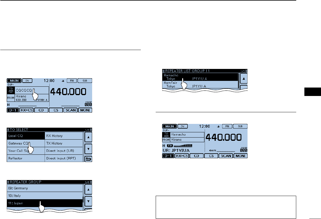
Set “TO” (Destination)2.
Touch the “TO” field. u
• Check whether “TO” is selected.
Touch the “TO” field again. i
• Opens the “TO SELECT” screen.
Touch “Gateway CQ.” o
• Opens the “REPEATER GROUP” screen.
!0 Touch the repeater group where your desired destination
repeater is listed. (Example: “11: Japan”)
!1 Touch your destination repeater.
(Example: “Hamacho”)
• Returns to the DR screen, and the selected repeater name is
displayed in “TO.”
Hold down [PTT] to transmit3.
• The LED1 on the microphone lights red.
For your reference:
The Gateway CQ call is used to call any repeater, but you
can call a specific station by simply saying their call sign.
41
4D-STAR OPERATION
New2001 New2001
Calling an individual station ■
You can make a call to an individual station when the station
call sign is selected in “TO” (Destination).
When you call an individual station call sign through a gate-
way, your call is automatically sent to the last repeater that
the station accessed. So, even if you don’t know where the
station is, you can make a call using call sign routing.
Set “FROM” (Access repeater)1.
Touch [DR]. qCheck whether or not “FROM” is selected. w
• If “FROM” is not selected, touch the “FROM” eld.
Touch the “FROM” field. e
• Opens the “FROM SELECT” screen.
Touch “Repeater List.” r
• Opens the “REPEATER GROUP” screen.
Touch the repeater group where your access repeater is tlisted. (Example: “11: Japan”)
Touch your access repeater. (Example: “Hirano”) y
• Returns to the DR screen, and the selected repeater name is
displayed in “FROM.”
New2001
42
4
D-STAR OPERATION
4
D-STAR OPERATION
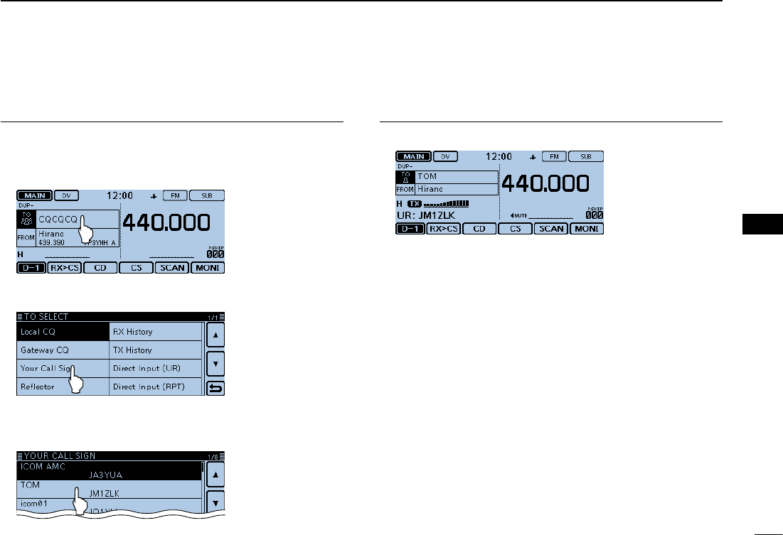
Set “TO” (Destination)2.
Touch the “TO” field. u
• Check whether “TO” is selected.
Touch the “TO” field again. i
• Opens the “TO SELECT” screen.
Touch “Your Call Sign.” o
• Opens the “YOUR CALL SIGN” screen.
!0 Touch the destination station. (Example: “TOM”)
• Returns to the DR screen, and the selected station name is dis-
played in “TO.”
Hold down [PTT] to transmit3.
• The LED1 on the microphone lights red.

43
4D-STAR OPERATION
New2001 New2001
Troubleshooting ■
To communicate through the repeater, your signal must access to the repeater. When your signal accesses your local repeater,
but it is not sent to the destination repeater, the repeater replies with an status message.
PROBLEM POSSIBLECAUSE SOLUTION REF.
After your call, the repeater does
not return a status reply. • The repeater setting is wrong.
• Your transmission did not reach the repeat-
er.
• Select the correct repeater.
• Correct the repeater frequency, frequency
offset, or duplex setting.
• Wait until you are closer to the repeater and
try again.
• Try to access another repeater.
p. ?
p. ?
—
—
After your call, the repeater
replies ‘UR?’ and its call
sign.
• The call was successfully sent, but no sta-
tion immediately replied. • Wait for a while, and try again. —
After your call, the repeater
replies ‘RX’ or ‘RPT?’ and the
access repeater’s call sign.
• Your call sign (MY) has not been set.
• Your call sign (MY) has not been registered
on a gateway repeater, or the registered
contents do not match your transceiver’s
setting.
• Set your call sign (MY).
• Register your call sign (MY) on a D-STAR
repeater, or confirm the registration of the
call sign.
p. ?
p. ?
New2001
44
4
D-STAR OPERATION
4
D-STAR OPERATION
PROBLEM POSSIBLECAUSE SOLUTION REF.
After your call, the repeater re-
plies ‘RPT?’ and call sign of the
destination repeater.
• The repeater cannot connect to the destina-
tion repeater.
• The repeater is busy.
• Check the repeater setting.
• Wait for a while, and try it again.
p. ?
—
After your call, the access re-
peater replies ‘RPT?’ and its call
sign.
• The call sign of the destination repeater is
wrong. • Correctly set the destination repeater call
sign.
p. ?
Even holding down [DR], the DR
screen will not appear.
• There is no repeater list in your radio. • Reload the repeater list using the SD card.
• Enter the Repeater list data directly into the
transceiver.
p. ?
Section 7 of the
Full Instruction
Even holding down [RX>CS], the
received call sign will not set to
the destination call sign.
• The call sign has not been correctly re-
ceived.
• When a received signal is weak, or a signal
is received during scanning, the call sign
may not be received correctly. In that case,
“--------” appears and error beeps sound,
and a reply call cannot be made.
• Try it again, after the transceiver has cor-
rectly received the call sign. —
A Local area call can be made,
but the Gateway call or destina-
tion station call cannot be made.
• MY call sign has not been registered at a
D-STAR repeater. • Register your call sign (MY) on a D-STAR
repeater, or confirm the registration of the
call sign.
p. ?
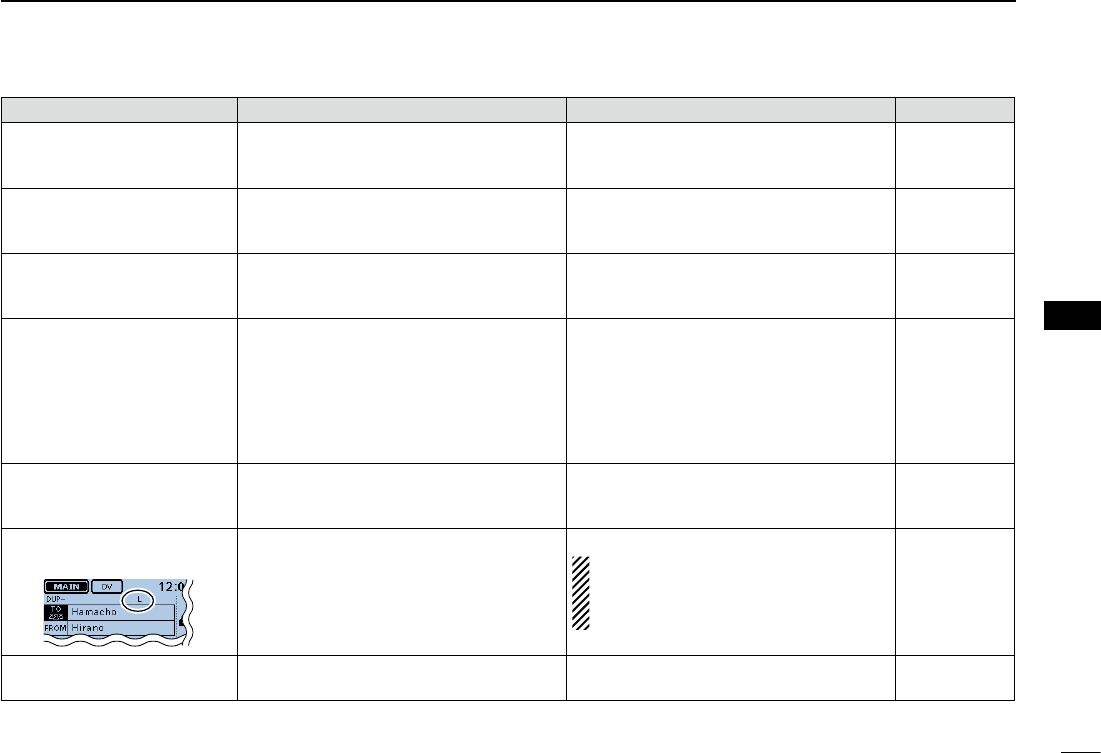
“L” appears on the LCD, and the
received audio is interrupted.
• While receiving through the internet, some
packets may be lost due to a network error
(poor data throughput performance).
• Wait a while, and try it again.
When the transceiver receives corrupted
data, and misidentifies it is as packet loss,
“L” is displayed, even if it is a Local area
call.
—
“DV” and “FM” icons alternately
blink. • While in the DV mode, an FM signal is re-
ceived. • Wait a while, and try it again.
p. ?
45
4D-STAR OPERATION
New2001 New2001
Reflector operation ■
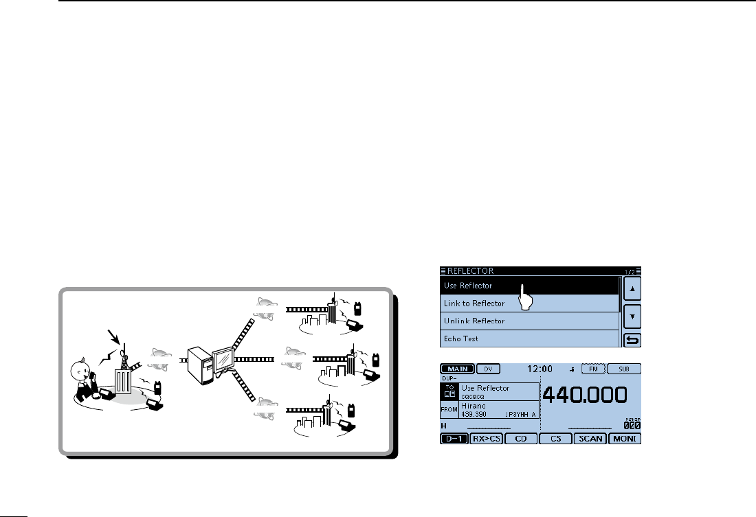
What is the reflector? D
A reflector is a special server connected to the internet and
running a version of dplus software. If the dplus software is
installed on your access repeater, it provides various functions
including gateway and reflector linking capabilities (It is known
as the D-STAR reflector system). The D-STAR reflector system
enables a number of D-STAR repeaters around the world to
link to a reflector. This means that when you transmit through
a D-STAR repeater linked to a reflector, your voice can be
heard on other repeaters linked to the reflector, and you can
hear other stations that are connected to the reflector.
Reflector
INTERNET
INTERNET
INTERNET
INTERNET
Access repeater USA
UK
AUS
JPN
D-STARreectorsystem
Using a reflector DTouch [DR]. qCheck whether or not “TO” is selected. w
• If “TO” is not selected, touch the “TO” eld.
Touch the “TO” field. e
• Opens the “TO SELECT” screen.
Touch “Reflector.” r
• Opens the “REFLECTOR” screen.
Touch “Use Reflector.” t
• The transceiver returns to the DR screen.
• “Use Reector” and “CQCQCQ” are displayed in “TO.”
Hold down [PTT] to transmit. y
• The LED1 on the microphone lights red.
New2001
46
4
D-STAR OPERATION
4
D-STAR OPERATION
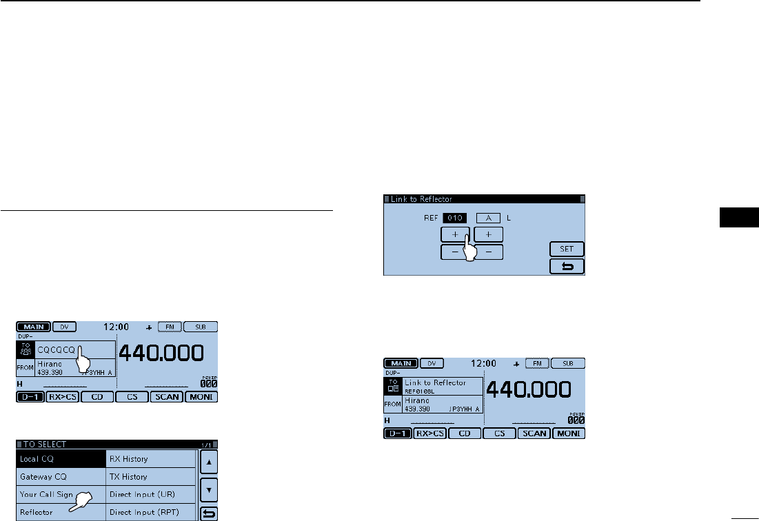
Linking to a reflector D
If your repeater is not currently linked to a reflector, or you
want to change to another reflector, you can do so following
the steps below. Before linking to another reflector, be sure to
unlink the current reflector. (p. ??-??)
Direct inputting
Example: Directly enter “REF010BL.”
Touch [DR]. qCheck whether or not “TO” is selected. w
• If “TO” is not selected, touch the “TO” eld.
Touch the “TO” field. e
• Opens the “TO SELECT” screen.
Touch “Reflector.” r
• Opens the “REFLECTOR” screen.
Touch “Link to Reflector.” t Touch “Direct Input.” y Touch [+] or [–] one or more times to select the reflector unumber. (Example: 010)
• Touch [] to cancel, and then return to the previous screen.
Touch [+] or [–] one or more times on the right-end box to iselect the module letter. (Example: B)
Touch [SET]. o
• The transceiver returns to the DR screen.
• “Link to Reector” and “REF010BL” are displayed in “TO.”
!0 Hold down [PTT] to link to the reflector.
• The LED1 on the microphone lights red.
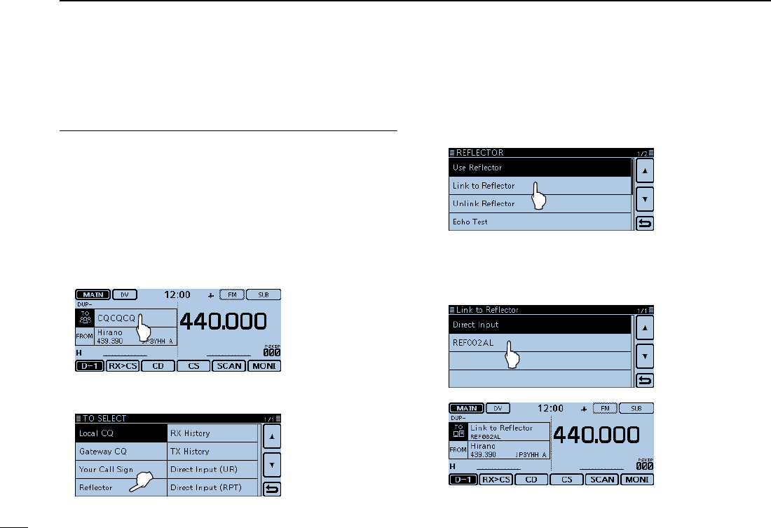
47
4D-STAR OPERATION
New2001 New2001
Reflector operation ■Linking to a reflector (Continued) D
Using the TX History
The TX History stores the up to 5 reflectors that your access
repeater linked before.
Example: Select the “REF002AL” in the TX History.
Touch [DR]. qCheck whether or not “TO” is selected. w
• If “TO” is not selected, touch the “TO” eld.
Touch the “TO” field. e
• Opens the “TO SELECT” screen.
Touch “Reflector.” r
• Opens the “REFLECTOR” screen.
Touch “Link to Reflector.” t
Touch the reflector that you want to link to. y
(Example: “REF002AL”)
• The transceiver returns to the DR screen.
• “Link to Reector” and “REF002AL” are displayed in “TO.”
!0 Hold down [PTT] to link to the reflector.
• The LED1 on the microphone lights red.
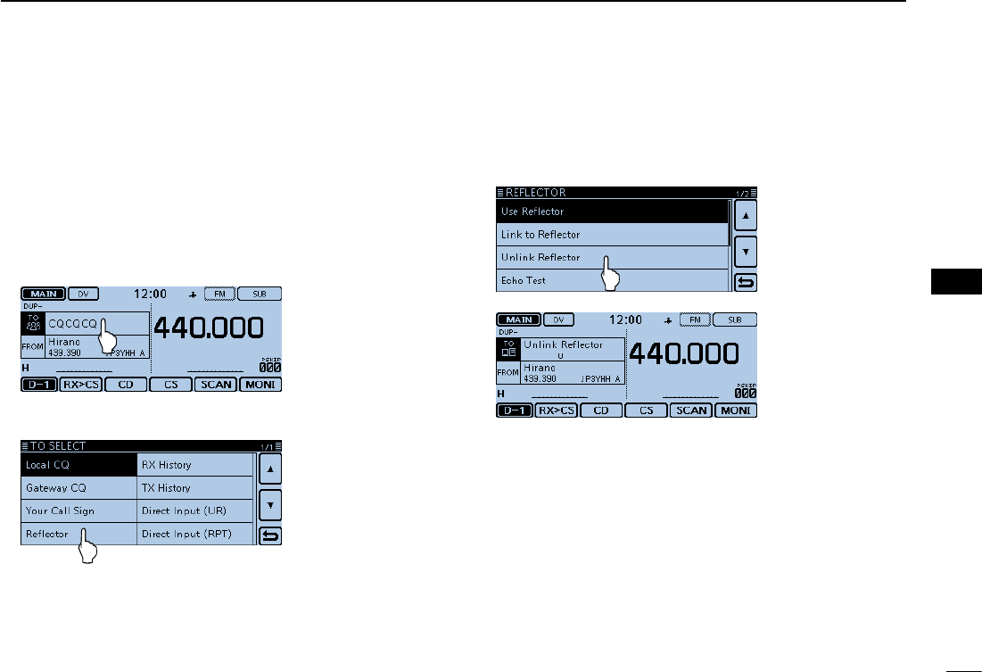
New2001
48
4
D-STAR OPERATION
4
D-STAR OPERATION
Unlinking a reflector D
Before linking to another reflector, be sure to unlink the cur-
rent reflector.
Touch [DR]. qCheck whether or not “TO” is selected. w
• If “TO” is not selected, touch the “TO” eld.
Touch the “TO” field. e
• Opens the “TO SELECT” screen.
Touch “Reflector.” r
• Opens the “REFLECTOR” screen.
Touch “Unlink Reflector.” t
• The transceiver returns to the DR screen.
• “Unlink Reector” and “U” are displayed in “TO.”
Hold down [PTT] to unlink the reflector. y
• The LED1 on the microphone lights red.
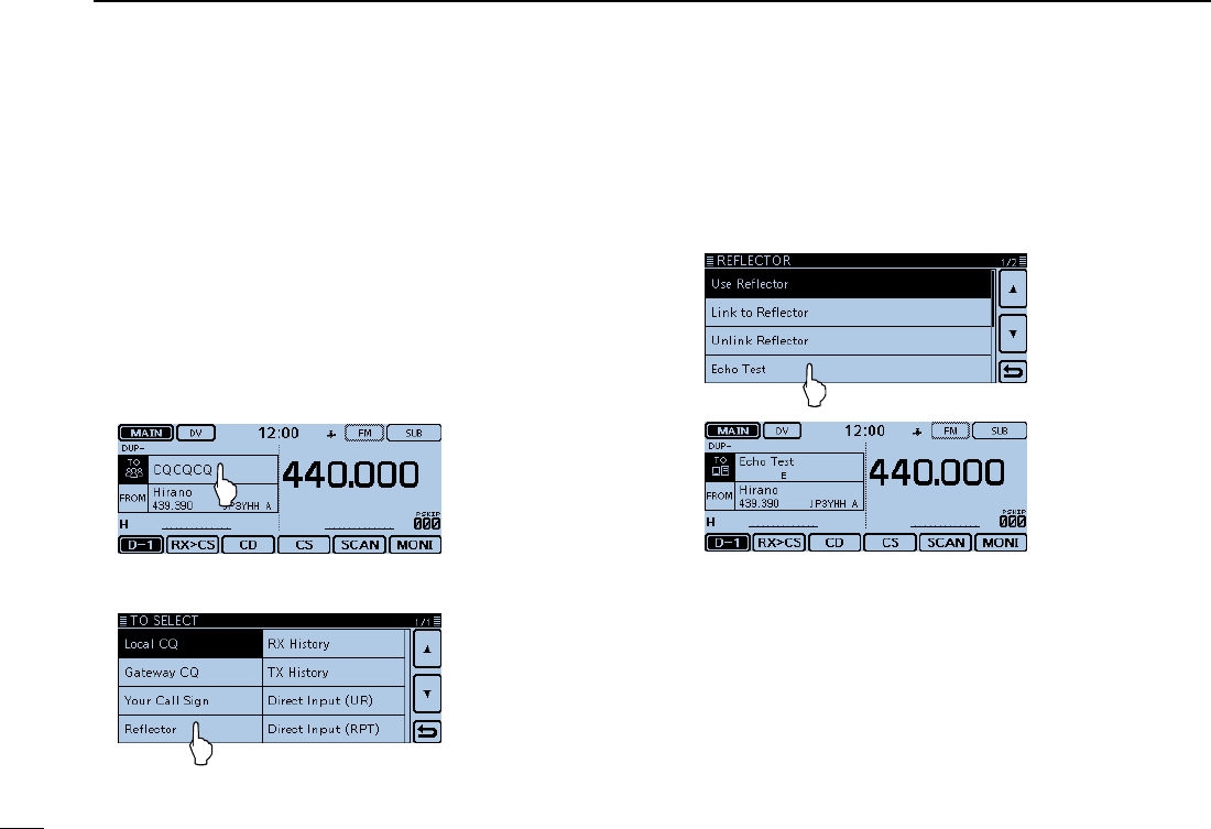
49
4D-STAR OPERATION
New2001 New2001
Reflector operation (Continued) ■
Reflector Echo Testing D
You can transmit a short message, and after releasing [PTT],
your message will be played back. It is a useful check of how
well your signal is getting into the repeater, and you can use it
to verify that your repeater is operating normally.
Touch [DR]. qCheck whether or not “TO” is selected. w
• If “TO” is not selected, touch the “TO” eld.
Touch the “TO” field. e
• Opens the “TO SELECT” screen.
Touch “Reflector.” r
• Opens the “REFLECTOR” screen.
Touch “Echo Test.” t
• The transceiver returns to the DR screen.
• “Echo Test” and “E” are displayed in “TO.”
Hold down [PTT] and speak into the microphone. y
• The LED1 on the microphone lights red.
Release [PTT] to hear your message. u
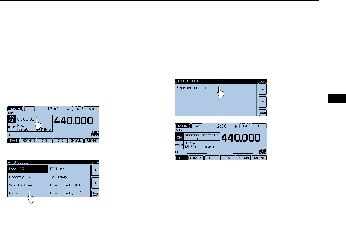
New2001
50
4
D-STAR OPERATION
4
D-STAR OPERATION
Requesting repeater information D
When you send the repeater information command, an ID
message is sent back.
Touch [DR]. qCheck whether or not “TO” is selected. w
• If “TO” is not selected, touch the “TO” eld.
Touch the “TO” field. e
• Opens the “TO SELECT” screen.
Touch “Reflector.” r
• Opens the “REFLECTOR” screen.
Touch [ t√] to select the next page.
Touch “Repeater Information.” y
• The transceiver returns to the DR screen.
• “Repeater Information” and “I” are displayed in “TO.”
Hold down [PTT] to send the repeater information com- umand.
• The LED1 on the microphone lights red.
Release [PTT] to hear the repeater ID message. i
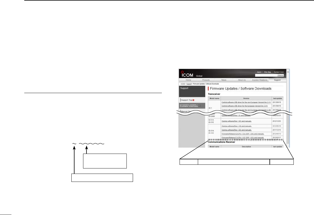
51
4D-STAR OPERATION
New2001 New2001
Updating the repeater list ■
For easy operation, the repeater list is preloaded into your
transceiver.
This section describes how to manually update the repeater
list using an SD card.
The latest setting file, which includes the repeater list, can be
downloaded from the Icom website.
Downloading the latest setting file (ICF file)1.
q Access the following URL to download the latest data.
http://www.icom.co.jp/world/support/download/firm/index.
html
• The latest settings le (ICF le) and repeater list (CSV: Comma
Separated Values file) are contained in the downloaded ZIP file.
File Name: 5100_U_140401.zip (Example)
Depending on the
updated file date.
Depending on the version.
ID-5100’s latest setting file is uploaded to “Cloning
software(Rev. MM) and manuals” on the Icom website
screen.
• The displayed contents may differ.
ID-5100 Cloning software(Rev. MM) and manuals
2014/MM/MM
w Decompress the compressed file that you downloaded
from the Icom website.
The “5100_U_140401” folder will be created in the same
place where the downloaded file is saved.
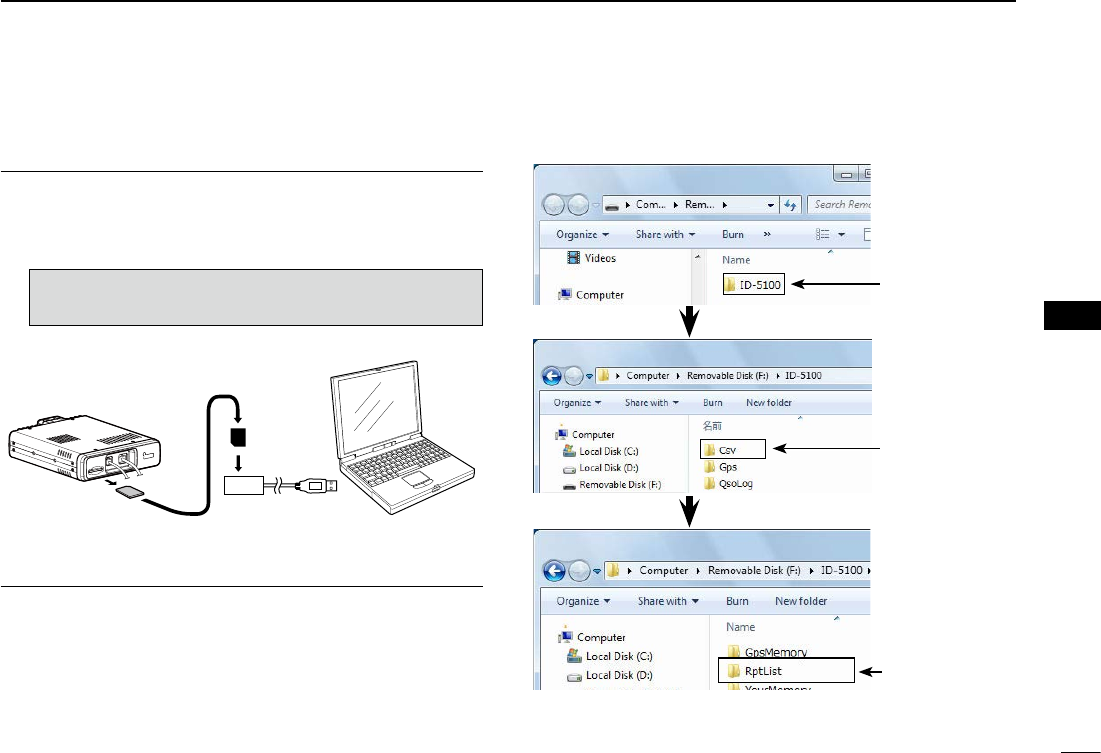
New2001
52
4
D-STAR OPERATION
4
D-STAR OPERATION
Continued on the next page ☞
Inserting the SD card into a PC2.
e Insert the SD card into the SD card drive on your PC.
• Icom recommends that you format all SD cards to be used with
the ID-5100, even preformatted SD cards for PCs or other uses.
(p. ??-??)
See page ??-?? and ??-?? for details on inserting
and removing the SD card.
SD card
Transceiver
to the external
card reader
PC
Copying the latest ICF file to the SD card3.
r Double-click the “5100_U_140401” folder created in the
same place where the downloaded file is saved.
t Copy the CSV file (Example: “5100_USA_140401.csv”) in
the folder to [RptList] of the SD card.
[ID-5100] > [CSV] > [RptList] The copied CSV
file is placed here
Double-
Click
Double-
Click
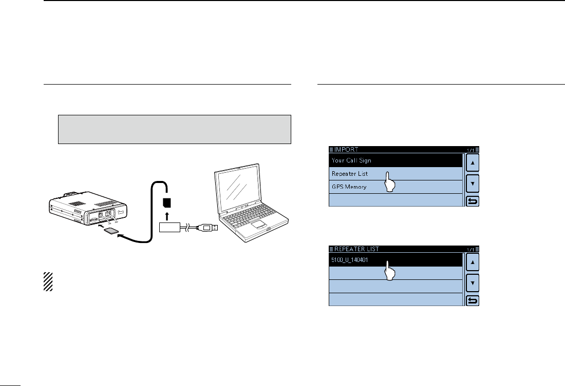
53
4D-STAR OPERATION
New2001 New2001
Updating the repeater list (Continued) ■
Inserting the SD card4.
y Remove the SD card from your PC, and insert it into the
transceiver’s slot.
See page ??-?? for details on inserting the SD
card into the transceiver.
SD card
Transceiver
from the external
card reader
PC
Icom recommends that you save the current data before
loading other data into the transceiver.
Updating the repeater list5.
u Touch [MENU].
i Touch [Repeater list].
(SD Card > Import/Export > Import > Repeater list)
• If the item is not displayed, touch [∫] or [√] one or more times to
select another page.
o Touch the CSV file to be loaded.
(Example: “5100_USA_140401.csv”)
• The “Keep 'SKIP' settings in Repeater List?” window appears.
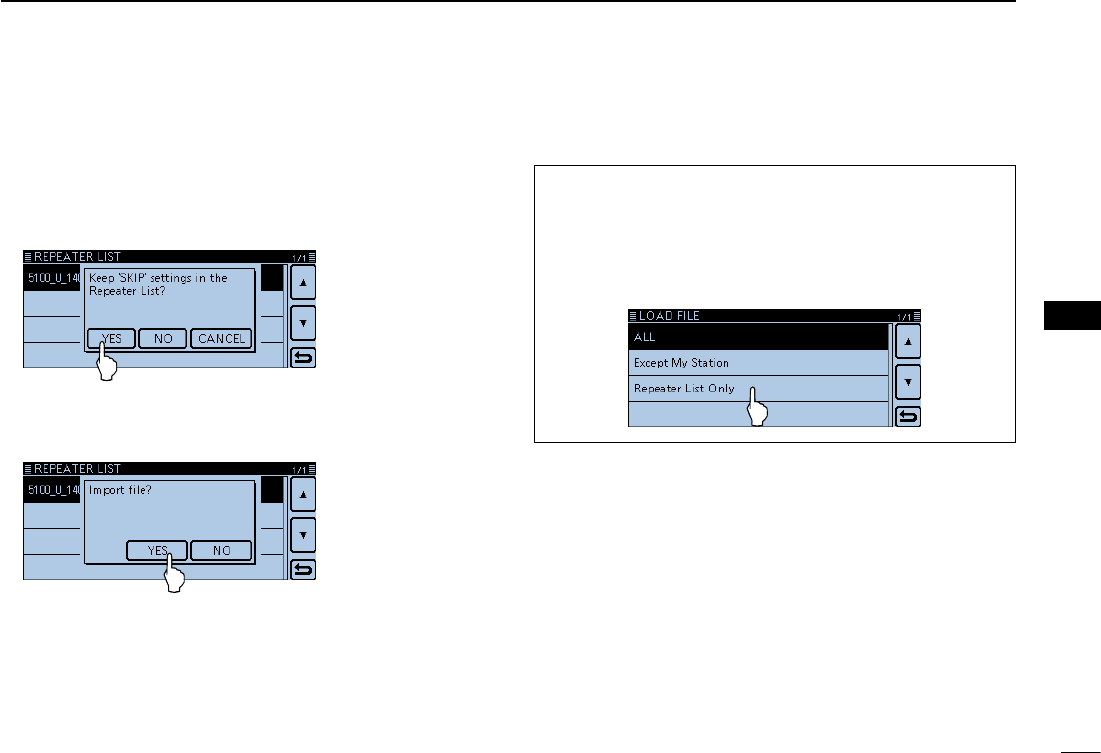
New2001
54
4
D-STAR OPERATION
4
D-STAR OPERATION
!0 Touch [YES] or [NO].
• When you touch [YES], the skip settings of the repeater list are
retained.
• When you touch [Cancel], returns to the “LOAD FILE” screen.
!1 When the “Import file?” appears, Touch [YES].
• Starts to import.
• While importing, “IMPORT” and a progress bar are displayed.
!4 After importing ends, “COMPLETED!” appears.
To complete the importing, reboot the transceiver.
For your reference:
If you copy the ICF file to [Setting] of the SD card, the re-
peater list can be updated with the same procedures. In this
case, touch “Load Setting.”
(SD Card > Load Setting)
In the LOAD FILE screen, touch “Repeater List Only.”
New2001
55
New2001New2001
RECORDING A QSO ONTO AN SD CARD
5
About the SD card ■
The SD and SDHC cards are not available from Icom. Pur-
chase separately.
An SD card of up to 2 GB, or an SDHC of up to 32 GB, can
be used with the ID-5100.
Icom has checked the compatibility with the following SD and
SDHC cards.
(As of March 2014)
Brand Type Memory size
SanDisk®
SD 2 GB
SDHC
4 GB
8 GB
16 GB
32 GB
• The above list does not guarantee the card’s performance.
• Throughout the rest of this document, the SD card and an
SDHC card are simply called SD cards.
• Icom recommends that you format all SD cards to be used
with the ID-5100, even preformatted SD cards for PCs or
other uses.
Saving the factory default data is recommended. Insert the
card into the transceiver’s slot, and then touch [MENU].
Touch “SD Card,” and then “Save Setting” to save.
NOTE:
• Before using the SD card, read the instructions of the SD
card thoroughly.
• If you do any of the following, the SD card data may be
corrupted or deleted.
- You remove the SD card from the transceiver while ac-
cessing the SD card.
- You change the external power supply’s voltage while
accessing the SD card.
- You start the vehicle engine while accessing the SD
card.
- You drop, impact or vibrate the SD card.
• Do not touch the contacts of the SD card.
• The transceiver takes a longer time to recognize a high
capacity SD card.
• The SD card will get warm if used continuously for a long
period of time.
• The SD card has a certain lifetime, so data reading or writ-
ing may not be possible after using it for a long time pe-
riod.
• When reading or writing data is impossible, the SD card’s
lifetime has ended. In this case, purchase a new one. We
recommend you make a backup file of the important data
onto your PC.
• Icom will not be responsible for any damage caused by
data corruption of an SD card.
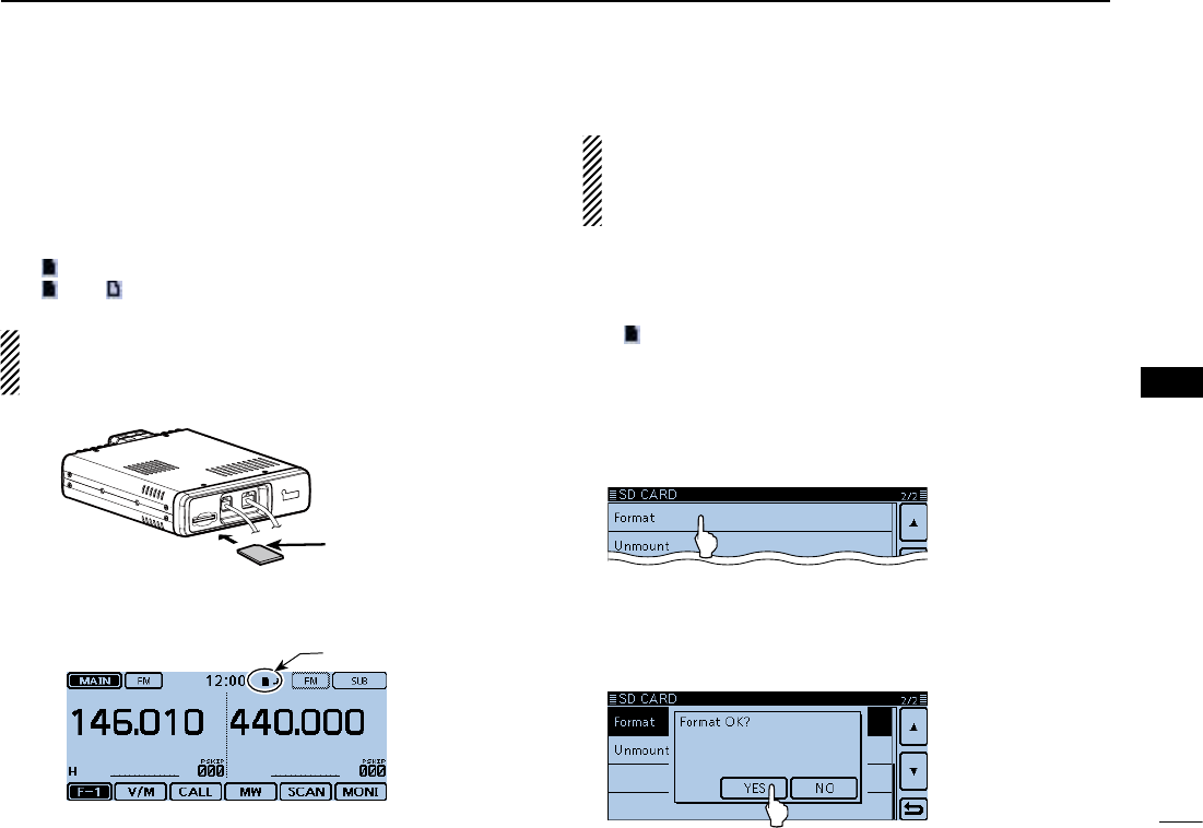
56
5
RECORDING A QSO ONTO AN SD CARD
New2001
5
RECORDING A QSO ONTO
AN SD CARD
New2001
Inserting the SD card ■
Inserting the SD card DTurn OFF the transceiver. q Insert the card into the slot until it locks in place, and wmakes a ‘click’ sound.
• “ ” is displayed when the SD card is inserted.
• “ ” and “ ” alternately blink while accessing the SD card.
NOTE: Before inserting, be sure to check the card direc-
tion. If the card is forcibly or inversely inserted, it will dam-
age the card and/or the slot.
Terminals
facing down
Cut corner side
Front panel
(Main unit)
SD card
Displayed
Formatting the SD card D
• If you use a brand new SD card, format it by doing the
following steps.
• Formatting a card erases all its data. Before formatting
any used card, back up its data onto your PC.
Turn OFF the transceiver, and then insert the card into the qslot.
Turn ON the transceiver. w
• “ ” appears when the SD card is inserted.
Touch [MENU]. e Touch “SD Card.” r
• If the item is not displayed, touch [∫] or [√] one or more times to
select the page.
Touch “Format.” t
• The conrmation window “Format OK?” appears.
Touch [YES]. y
• The formatting starts and the display shows the formatting prog-
ress.
• After formatting ends, the display automatically returns to the
screen displayed before the “Format OK?” window.
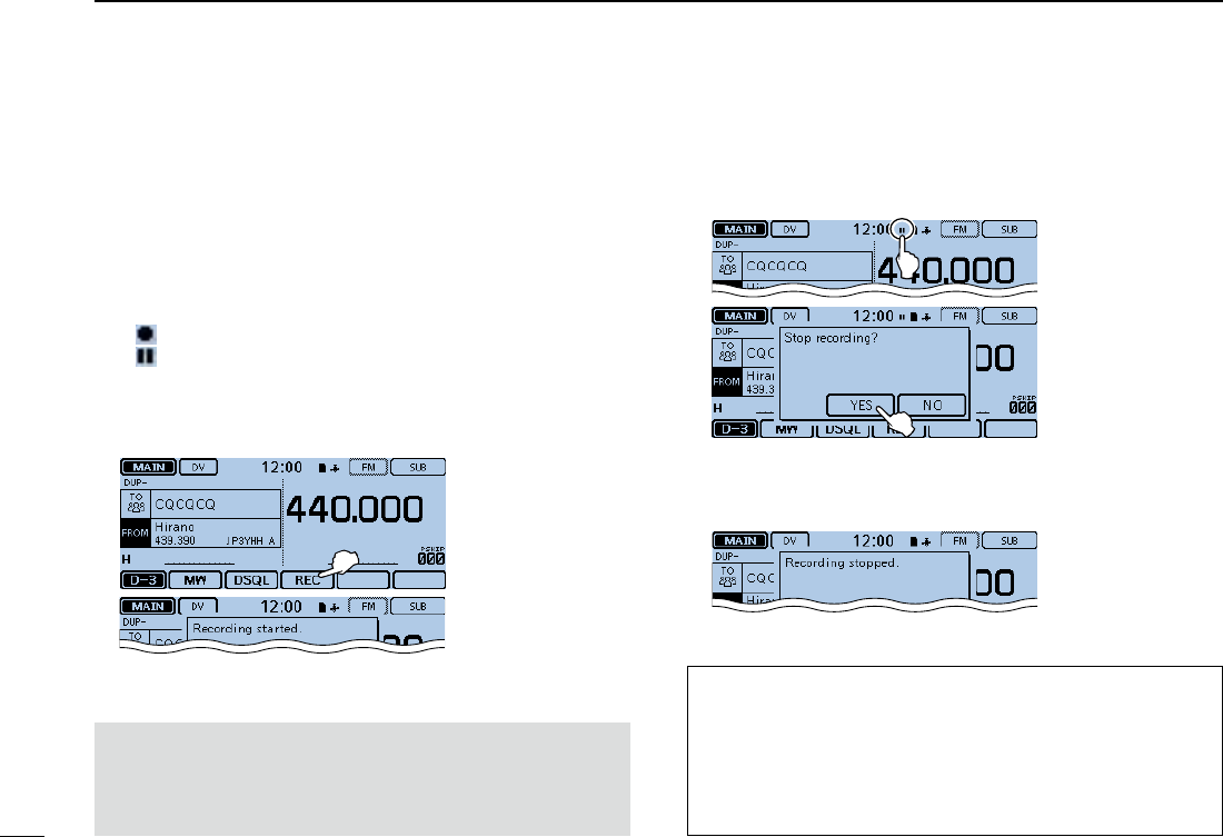
57
5RECORDING A QSO ONTO AN SD CARD
New2001 New2001
Recording a QSO audio ■
Touch the Function group icon one or more times. q
• When displaying the DR screen, selects the D-3 menu.
• While in the VFO, Memory or Call CH mode, displays the F-3
menu.
Touch [REC]. w
• The “Recording started” dialog box appears, and voice recording
starts.
• “ ” is displayed while the transceiver is recording.
• “ ” is displayed while the recording is paused.
• Recording is continuous until you manually stop recording, or
the card becomes full.
• If the recording le’s content reaches 2GB, the transceiver auto-
matically creates a new file, and continues recording.
Touch the record icon. e
• The “Stop recording?” dialog box appears.
Touch [YES]. r
• The “Recording stopped” dialog box appears, and voice record-
ing stops.
For your reference:
When the PTT Automatic Recording function is set to ON
in the MENU screen, the recording automatically starts
when [PTT] is pushed.
( Voice Memo > QSO Recorder > Recorder Set >
PTT Auto REC)
NOTE:
Once the voice recording starts, it will continue until
you stop recording, even if you turn OFF the trans-
ceiver.
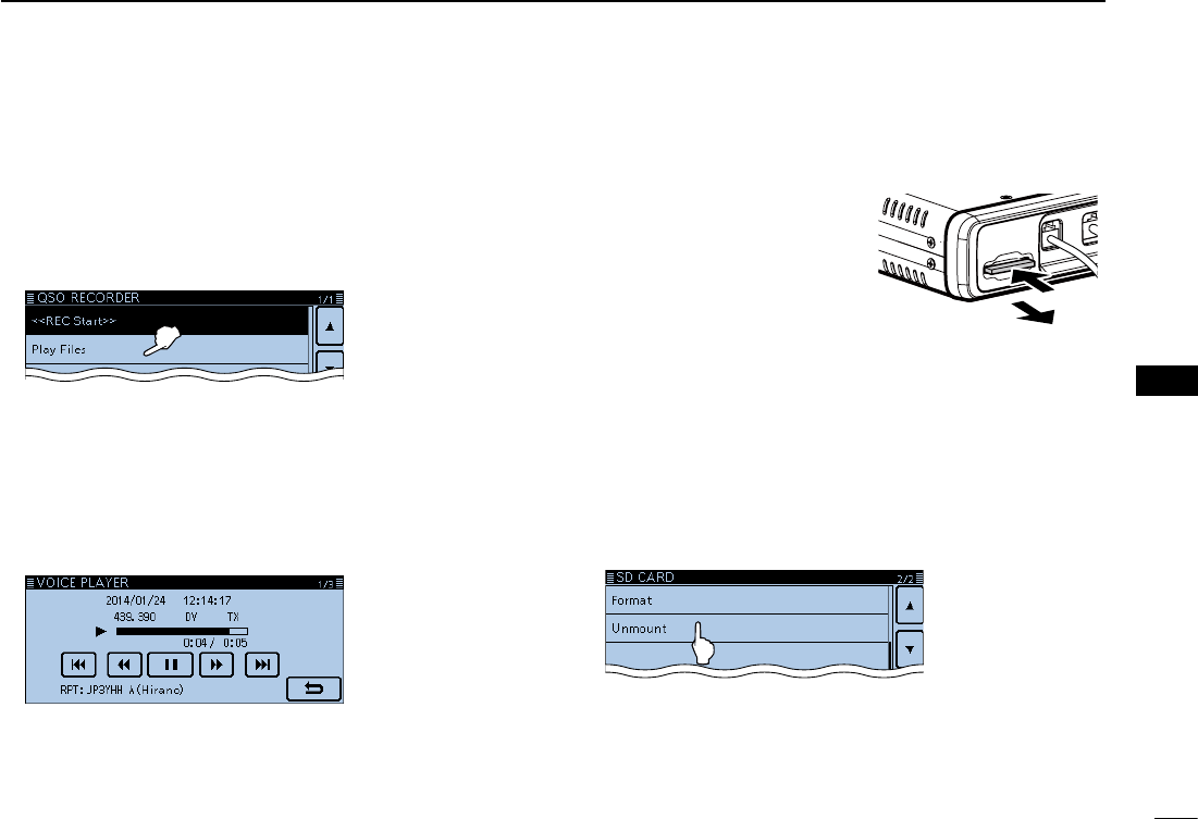
New2001
58
5
RECORDING A QSO ONTO AN SD CARD
5
RECORDING A QSO ONTO
AN SD CARD
Removing the SD card ■
Push
Pull out
Removing the SD card while the transceiv- Der’s power is ON
Touch [MENU]. q Touch “SD Card.” w
• If the item is not displayed, touch [∫] or [√] one or more times to
select the page.
Touch “Unmount.” e
• The conrmation window “Unmount OK?” appears.
Touch [YES]. r
• When the unmounting is completed, “Unmount is completed.” is
displayed, then the display automatically returns to the screen
displayed before the “Unmound OK?” window.
Push in the SD card until a click sounds, and then carefully tpull it out.
Removing the SD card DTurn OFF the power. q Push in the SD card until a wclick sounds, and then care-
fully pull it out.
Front panel
(Main unit)
Playing back the recorded audio ■
Touch [MENU]. qTouch “Play Files.” w
(Voice Memo > QSO Recorder > Play Files)
• If the item is not displayed, touch [∫] or [√] one or more times to
select another page.
Touch the folder that contains the file you want to play. e
• The le list is displayed.
• The folder name is named yyyymmdd (y: year, m: month,
d: day.)
Touch the file that you want to play. r
• The “VOICE PLAYER” screen is displayed, and the le starts to
playback.
• See the Full Instructions for details.
Touch [MENU]. t
• Stops the playback, and close the “VOICE PLAYER”
screen.
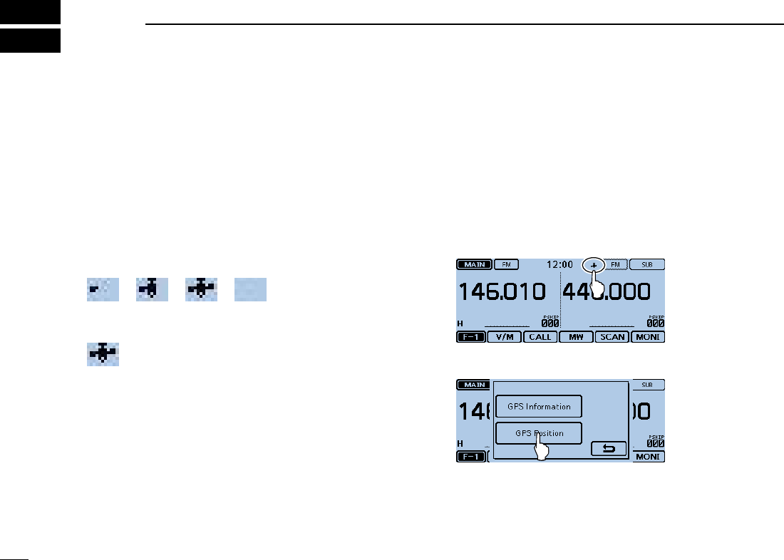
59
New2001New2001
GPS OPERATION
6
GPS operation ■
The transceiver has a built-in internal GPS receiver.
You can check your current position, and transmit GPS
data in the DV mode.
GPS receive setting D
Check whether or not the GPS receiver is receiving your posi-
tion.
The GPS icon blinks when searching for satellites.
➪ ➪ ➪
The GPS icon stops blinking when the minimum needed
number of satellites is found.
• It may take only a few seconds to receive. But depending on the
environment, it may take a few minutes. If you have difficulties re-
ceiving, we recommend that you try a different location.
• When “GPS Select” item is set to “Manual,” the icon does not ap-
pear.
(GPS > GPS Set > GPS Select)
Checking your GPS position ■
You can check your current position.
If you transmit while displaying the GPS position screen, the
screen closes.
But you can check your current position, RX position, and so
on by touching the GPS icon while transmitting.
Displaying Position Data DTouch the GPS icon. q
Touch [GPS Position]. w
• Opens the “GPS POSITION” screen.
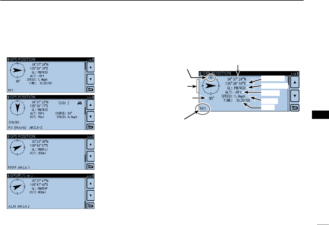
New2001
60
6
CALLING A DESTINATION STATION
6
CALLING A DESTINATION STATION
“GPS POSITION” screen (MY)
Latitude
Time
Compass
direction top
is North.
Your course
heading is
East.
Your course
direction is
95° degrees.
Shows My
position
Altitude
Grid locator
Speed
Longitude
Touch [ e∫] or [√] one or more times.
• Selects the page.
GPS memory
position screen
(MEM)
Received position
screen (RX)
My position
screen (MY)
GPS alarm
position screen
(ALM)
Touch [ r].
• Closes the “GPS POSITION” screen.
About the GPS Position screen D
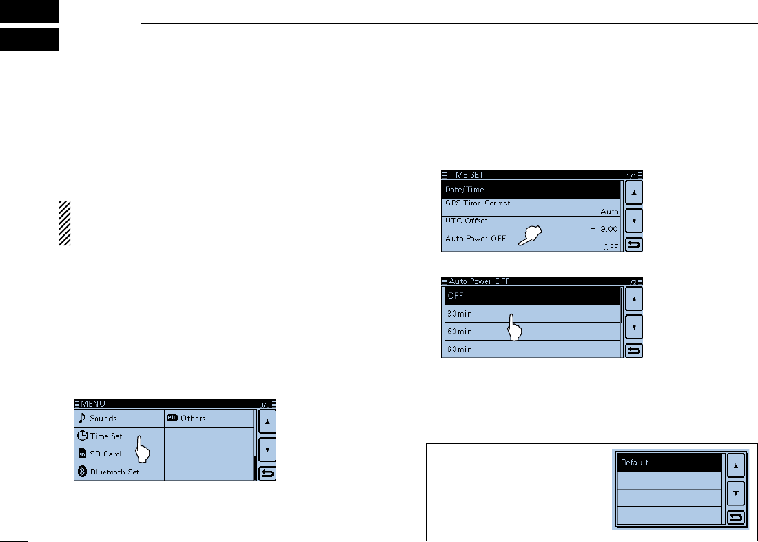
New2001
61
New2001
MENU SCREEN
7
Menu item selection ■
The Menu screen is used to program infrequently changed
values or function settings.
In addition to this page, see pages ?? through ?? for details
of each item’s options and their default value.
NOTE: The Menu system is constructed in a tree structure.
You may go to the next tree level, or go back a level, de-
pending on the selected item.
Entering the Menu screen D
Example: Set the Auto Power OFF function to “30 min.”
Touch [MENU]. q Touch [ w∫] or [√] one or more times to select the page.
• If you continuously hold down [∫] or [√], the items are quickly
scrolled.
• To set other item, touch [] to go back a tree level.
Touch “Time Set.” e
To return to the default setting,
touch [QUICK] in step t, and
then touch “Default,”.
Touch “Auto Power OFF.” r
• If you continuously touch [∫] or [√], the items are quickly
scrolled.
Touch “30min.” t
Touch [MENU] y
• Closes the Menu screen.

62
7
MENU SCREEN
New2001
7
62
DUP/TONE... Settings to access repeaters.
Offset Freq 0.000~0.600.00*~59.995 MHz Sets the frequency offset for duplex (repeater) op-
eration.
* The default value may differ, depending on the frequency
band (selected as the MAIN band before entering the
Menu screen) and the transceiver version.
Repeater Tone 67.0~88.5~254.1 Hz Selects a tone frequency used to access the repeat-
ers.
TSQL Freq 67.0~88.5~254.1 Hz Selects a tone frequency for the Tone squelch or the
pocket beep function.
Tone Burst OFF or ON
Turns the Tone Burst function ON or OFF.
This function is used to suppress the squelch tail noise
heard from the transceier's speaker.
DTCS Code 023~754 Selects a DTCS (both encoder/decoder) code for
DTCS squelch or the pocket beep function.
DTCS Polarity BothN, TN-RR, TR-RN or Both R Selects the DTCS polarity for the DTCS squelch or
the pocket beep function.
Digital Code 00~99 Selects a digital code for the Digital Code squelch
function.
Manage Memory Manage your Memory or Call channel data.
Memory CH ALL, A~Z Manages for the Memory channels.
Call CH C0/C1(144):146.010 FM
C0/C1(430):440.000 FM Manages for the Call channels.
Menu items and Default settings ■
NOTE: The default settings shown in bold letters below are for the USA version.
The default settings may differ, depending on your transceiver version.
MENU SCREEN

63
7MENU SCREEN
New2001 New2001
Scan Set scan options.
Pause Timer 2sec~10sec~20sec or HOLD Selects the scan pause time. When receiving signals,
the scan pauses according to the scan pause timer.
Resume Timer 0sec~2sec~5sec or HOLD
Selects the scan resume time from a pause after the
received signal disappears.
Temporary Skip Timer 5min, 10min or 15 min
Selects the Temporary Skip Time. When the time is
set, specified frequencies are skipped for this period
during a scan.
Program Skip OFF or ON Turns the Program Skip Scan function ON or OFF for
a VFO mode scan.
Bank Link A:✔~Z:✔Selects banks to be scanned during a Bank Link
Scan.
Program Scan Edge 00~24 Sets the frequency ranges for the program scan.
Program Link
See page ??-?? on the ??? for details of the preset values. Sets the link function for the program scan edge
channels.
Voice Memo Set the TX/RX voice recording options.
QSO Recorder
<<REC Start>>*
Starts recording the received signal audio.
Play Files* PLAY FILES Plays or deletes the recorded audio.
Recorder Set
REC Mode TX&RX or RX Only Selects to record the TX audio or not.
RX REC Condition Always or Squelch Auto Selects whether or not the squelch status affects the
RX voice audio recording.
File Split OFF or ON Selects whether or not to automatically create a new
file if transmission and reception, or squelch status
(open and close) is switched.
Menu items and Default settings (Continued) ■
* Be sure to insert the SD card into the transceiver before selecting these items.

New2001
64
7
MENU SCREEN
7
MENU SCREEN
PTT Auto REC OFF or ON Turns the PTT Automatic Recording function ON or
OFF.
Player Set
Skip Time 3sec, 5sec, 10sec or 30sec
Sets the Skip time to rewind or forward the recorded
audio when you push the fast-rewind or fast-forward
key during playback.
DV Auto Reply* Records a voice audio to use the Auto Reply function
in the DV mode.
Voice TX Set microphone voice recording options.
Record
*
T1~T4 Starts recording the microphone audio.
TX Set
Repeat Time 1sec~5sec~15sec Sets the repeat interval. The transceiver repeatedly
transmits the recorded voice audio at this interval.
TX Monitor OFF or ON The TX Monitor function outputs the TX voice audio
from the speaker during voice transmission.
<<TX>>* T1~T4, Repeat TX The transceiver transmits the recorded voice audio.
GPS Set GPS options.
GPS Set
GPS Select OFF, Internal GPS or Manual Selects the position data source that the transceiver
uses for its position data.
Manual Position Manually enter your current position.
GPS Out (To DATA Jack) OFF or ON Selects to output the GPS information to the [DATA]
jack
GPS TX Mode
OFF Turns OFF the GPS TX function.
D-PRS
Unproto Address API510,DSTAR* Enters an unproto address, or keep the default.
* Be sure to insert the SD card into the transceiver before selecting these items.

65
7MENU SCREEN
New2001 New2001
TX Format
Position
Symbol
1:Car, 2:Van, 3:Truck or 4:House QTH (VHF)
Selects a desired D-PRS Symbol to transmit.
SSID ---, (-0), -1~-15 or -A~-Z Selects the APRS® call sign SSID.
Comment Enters a comment to transmit.
Time Stamp OFF, DHM or HMS Selects a format to transmit the current UTC time as
a time stamp.
Altitude OFF or ON Turns the altitude transmit option ON or OFF.
Data Extension OFF, Course/Speed or
Power/Height/Gain/Directivity Selects whether to transmit the course/speed data,
power/height/gain/directivity data or not.
Power 0W, 1W, 4W, 9W, 16W, 25W, 36W,
49W, 64W or 81W Selects the TX power level information to send when
using as a base station.
Height 10ft, 20ft, 40ft, 80ft, 160ft, 320ft,
640ft, 1280ft, 2560ft, 5120ft Selects the antenna height information to send when
using as a base station.
Gain 0dB~9dB Selects the antenna gain information to send when
using as a base station.
Directivity 0mni, 45°NE, 90°E, 135°SE, 180°S,
225°SW, 270°W, 315°NW, 360°N Selects the antenna directivity information to send
when using as a base station.
Object
Object Name Enters a object station name to transmit.
Data Type Live Object, Killed Object Selects a object station’s status to transmit.
Symbol Radio Selects a object station’s symbol to transmit.
Comment Enters a object station’s comment to transmit.
Position Sets a object station’s position data to transmit.
Data Extension OFF, Course/Speed or
Power/Height/Gain/Directivity
Selects whether to transmit the object station’s course/
speed data, power/height/gain/directivity data or not.
Course 0°~360° Sets a object station’s course to transmit.
Speed 0mph~1150mph Sets a object station’s speed to transmit.
Menu items and Default settings (Continued) ■

New2001
66
7
MENU SCREEN
7
MENU SCREEN
Power 0W, 1W, 4W, 9W, 16W, 25W, 36W,
49W, 64W or 81W Selects a object station’s TX power level to transmit.
Height 10ft, 20ft, 40ft, 80ft, 160ft, 320ft,
640ft, 1280ft, 2560ft, 5120ft Selects the antenna height of the object station to
transmit.
Gain 0dB~9dB Selects the antenna gain of the object station to
transmit.
Directivity 0mni, 45°NE, 90°E, 135°SE, 180°S,
225°SW, 270°W, 315°NW, 360°N Selects the antenna directivity of the object station
to transmit.
SSID ---, (-0), -1~-15 or -A~-Z Selects the APRS® call sign SSID for the object sta-
tion.
Time Stamp OFF, DHM or HMS Selects a format to transmit the current UTC time as
a time stamp.
Item
Item Name Enters a item station name to transmit.
Data Type Live Item, Killed Item Selects a item station’s status to transmit.
Symbol Radio Selects a item station’s symbol to transmit.
Comment Enters a item station’s comment to transmit.
Position Sets a item station’s position data to transmit.
Data Extension OFF, Course/Speed or
Power/Height/Gain/Directivity
Selects whether to transmit the item station’s course/
speed data, power/height/gain/directivity data or not.
Course 0°~360° Sets a item station’s course to transmit.
Speed 0mph~1150mph Sets a item station’s speed to transmit.
Power 0W, 1W, 4W, 9W, 16W, 25W, 36W,
49W, 64W or 81W Selects a item station’s TX power level to transmit.
Height 10ft, 20ft, 40ft, 80ft, 160ft, 320ft,
640ft, 1280ft, 2560ft, 5120ft Selects the antenna height of the item station to
transmit.
Gain 0dB~9dB Selects the antenna gain of the item station to trans-
mit.
Directivity 0mni, 45°NE, 90°E, 135°SE, 180°S,
225°SW, 270°W, 315°NW, 360°N Selects the antenna directivity of the item station to
transmit.

67
7MENU SCREEN
New2001 New2001
SSID ---, (-0), -1~-15 or -A~-Z Selects the APRS® call sign SSID for the item sta-
tion.
Weather
Symbol WX Station Selects a weather station’s symbol to transmit.
SSID ---, (-0), -1~-15 or -A~-Z Selects the APRS® call sign SSID for the weather
station.
Comment Enters a weather station’s comment to transmit.
Time Stamp OFF, DHM or HMS Selects a format to transmit the current UTC time as
a time stamp.
NMEA
GPS Sentence
RMC, GGA, GLL, VTG, GSA or GSV
Transmits position data in selected GPS sentences.
GPS Message Enter a GPS message to be transmitted.
GPS Information Displays the received GPS information.
GPS Position Displays your position, RX station,
GPS
memory and
Alarm positions.
GPS Memory (No Group), A~Z
Shows the GPS memory contents.
GPS Alarm
Alarm Select OFF, RX, Group or Memory Select the target for the GPS alarm function.
Alarm Area (Group) 0’05”/0.08’~0’15”/0.25’~
59’59”/59.99’ Enter the GPS alarm active range.
Alarm Area (RX/Memory) Limited, Extended or Both Select the GPS alarm active range.
GPS Logger*
GPS Logger OFF or ON Turns the GPS logger function ON or OFF, to store
your route as you move.
Record Interval 1sec, 5sec, 10sec, 30sec or 60sec Selects the GPS Logger function record interval.
GPS Auto TXOFF, 5sec, 10sec, 30sec, 1min,
3min, 5min, 10min or 30min Selects a time option for the GPS automatic trans-
mission function.
Menu items and Default settings (Continued) ■
* Be sure to insert the SD card into the transceiver before selecting these items.

New2001
68
7
MENU SCREEN
7
MENU SCREEN
Call Sign Set and display the DV mode call signs.
UR: CQCQCQ, R1: --------,
R2: --------, MY: -------- Displays the operating call signs.
Sets the operating call signs according to the type of
call you want to make.
RX History
Displays the received call history in the DV mode.
LAST (MAIN) Displays the calls your transceiver received.
DV Memory Stores call signs or repeater information to use in the DV mode.
Your Call Sign Blank Stores station call signs.
Add or edit call signs.
Repeater List
( See page ??-?? on ??? for details of
the preloaded data.)
01:~30: Stores repeater information.
Add or edit repeater information.
NOTE: The repeater list described in this manual may differ from your preloaded list.
My Station Sets and stores your call sign to use in the DV mode.
My Call Sign 1:~6: Stores your call signs.
Select or edit a call sign to use in the DV mode.
TX Message 1:~5: or OFF Stores TX Messages.
Select or edit TX Message to use in the DV mode.
DV Set Sets values for the DV mode operations.
Tone Control
RX Bass Cut, Normal or Boost Sets the DV mode received audio bass filter level to
Cut, Normal or Boost.
RX Treble Cut, Normal or Boost Sets the DV mode received audio treble filter level to
Cut, Normal or Boost.
RX Bass Boost OFF or ON Turns the DV mode received audio Bass Boost func-
tion ON or OFF

69
7MENU SCREEN
New2001 New2001
TX Bass Cut, Normal or Boost Sets the DV mode transmit audio bass filter level to
Cut, Normal or Boost.
TX Treble Cut, Normal or Boost Sets the DV mode transmit audio treble filter level to
Cut, Normal or Boost.
Auto Reply OFF, ON, Voice, Position (Main Only)
or Position (Main/Sub) Selects the Automatic Reply function.
DV Data TX PTT or Auto Selects manually or automatically to transmit low
speed data.
Digital Monitor Auto, Digital or Analog Selects the DV mode RX monitoring when [SQL] is
held down.
Digital Repeater Set OFF or ON Turns the digital repeater setting function ON or OFF.
This function is usable in any DV mode except using
the DR function.
DV Auto Detect OFF or ON Turns the DV mode automatic detect function ON or
OFF.
RX Record (RPT) ALL or Latest Only The transceiver can record the data of up to 50 indi-
vidual calls.
BK OFF or ON Turns the BK (Break-in) function ON or OFF. The BK
function allows you to break into a conversation be-
tween two stations with call sign squelch enabled.
EMR OFF or ON Turns the EMR (Enhanced Monitor Request) com-
munication mode ON or OFF.
After turning OFF the transceiver, the EMR mode will
be cancelled.
EMR AF Level 0~19~39 Sets the audio output level when an EMR mode sig-
nal is received.
Menu items and Default settings (Continued) ■

New2001
70
7
MENU SCREEN
7
MENU SCREEN
SPEECH Sets the Speech functions.
RX Call Sign SPEECH OFF, ON (Kerchunk) or ON (All) Selects the RX call sign speech function option while
ON, or turn it OFF.
RX>CS SPEECH OFF or ON Turns the RX>CS Speech function ON or OFF.
DIAL SPEECH OFF or ON Turn the Dial Speech function ON or OFF.
MODE SPEECH OFF or ON Turn the Operating Mode Speech function ON or
OFF.
SPEECH Language English or Japanese Selects either English or Japanese as the desired
speech language.
Alphabet Normal or Phonetic Code Selects the alphabet character announcement type.
SPEECH Speed Slow or Fast Selects Slow or Fast speech speed
SPEECH Level 0~7~9 Sets the volume level for the voice synthesizer.
DTMF Sets the DTMF Memory functions.
DTMF Memory d0:~d9:, dA:~dD:, d*: or d#: Shows a list of the DTMF memory channels. The
DTMF memory can store up to 24-digit DTMF code.
DTMF Speed 100ms, 200ms, 300ms or 500ms Selects the DTMF transfer speed.
QSO/RX Log Sets the QSO/RX History Log options.
QSO Log*1OFF or ON Selects to make a communication log on the SD
card, or not.
RX History Log
*1OFF or ON Selects to make a DV mode's receive history log on
the SD card, or not.
CSV Format
Separator/Decimal Sep [,] Dec [.]*2, Sep [;] Dec [.] or
Sep [;] Dec [,] Selects the separator and the decimal character for
the CSV format.
Date yyyy/mm/dd, mm/dd/yyyy*2 or dd/
mm/yyyy Selects the date format.
*1 Be sure to insert the SD card into the transceiver before selecting these items.
*2 The default value may differ, depending on the transceiver version.

71
7MENU SCREEN
New2001 New2001
Function Sets various function’s options.
Squelch/ATT Select OFF, S-MeterSquelch, ATT Selects to use the S-Meter Squelch or the Attenuator
function for the [SQL] control.
Squelch Delay Short, Long Selects to shorten or lengthen the time until the
squelch opens.
Fan Control Slow, Mid, Fast or Auto Selects the cooling fan control condition.
Dial Speed-UP OFF or ON Turns the dial speed acceleration ON or OFF.
Auto Repeater OFF or ON (DUP), ON (DUP,TONE) Turns the Auto Repeater function ON or OFF.
Remote MIC Key Selects the key function for [F-1] or [F-2] on the sup-
plied remote-control microphone.
During RX/Standby [F-1]:BAND/BANK [F-2]:MONITOR Selects the key function to be used while receiving or
in the standby mode.
During TX [F-1]:T-CALL [F-2]:--- Selects the key function to be used while transmit-
ting.
Up/Down MIC Key Selects the key function for [UP] or [DN] on the op-
tional hand microphone.
During RX/Standby [UP]:UP [DN]:DOWN Selects the key function to be used while receiving or
in the standby mode.
During TX [UP]:--- [DN]:--- Selects the key function to be used while transmit-
ting.
One-Touch PTT(Remote MIC) OFF or ON Turns the One-Touch PTT function ON or OFF.
PTT Lock OFF or ON Turns the PTT Lock function ON or OFF.
Busy Lockout OFF or ON Turns the Busy Lockout function ON or OFF.
Time-Out Timer OFF, 1min, 3min, 5min, 10min,
15min or 30min Selects the Time-Out Timer time options.
Active Band Single or All Allows
continuous frequency selection across all
bands by rotating [DIAL].
MIC Gain 1~2~4 Sets the microphone sensitivity to suit your prefer-
ence.
Menu items and Default settings (Continued) ■

New2001
72
7
MENU SCREEN
7
MENU SCREEN
Touch Operation (Sub) Main Select or Function Select Sets the touch operation on the SUB band display.
Keyboard Type Ten-key, Full keyboard Selects the keyboard input type to enter a call sign,
memory name, and so on.
Data Speed 4800bps or 9600bps Selects the data transmission speed for low-speed
communication, or between the [DATA] jack and ex-
ternal modules like a GPS receiver, and so on.
CI-V
CI-V Address 01~8Ch~DF Sets the transceiver's unique CI-V hexadecimal ad-
dress code.
CI-V Baud Rate 4800, 9600, 19200 or Auto Sets the CI-V code transfer speed.
CI-V TransceiveOFF or ON Turns the CI-V Transceive function ON or OFF.
CI-V Bluetooth➝REMOTE
transceive Address 00h~DFh Sets the address to inhibit the external control with
CI-V for the transceiver through the [SP2] (REMOTE)
jack.
Heterodyne
Heterodyne (A BAND VHF)
Normal or Reverse
Effective to eliminate internal spurious that may oc-
cur in a rare combination of dual band frequencies,
when operating VHF on the A band.
Heterodyne (A BAND UHF)
Normal or Reverse
Effective to eliminate internal spurious that may oc-
cur in a rare combination of dual band frequencies,
when operating UHF on the A band.
Heterodyne (B BAND UHF)
Normal or Reverse
Effective to eliminate internal spurious that may oc-
cur in a rare combination of dual band frequencies,
when operating UHF on the B band.
Power OFF (With No Controller) OFF or ON Selects whether or not to automatically turn OFF the
transceiver when the controller is disconnected from
the transceiver.

73
7MENU SCREEN
New2001 New2001
Display Sets the Display options.
Backlight 1~8 Selects the transceiver backlight option.
Auto Dimmer OFF, Auto-OFF, Auto-1~7 Sets the Auto dimmer function, and the dimmer lev-
el.
Auto Dimmer Timer 5sec, 10sec Selects the backlight ON time period.
Touch Operation (Dimmed) Brighten, Brighten&Action Selects whether or not to brighten and make an ac-
tion when you touch the dimmed panel.
LCD Contrast 1~8~16 Sets the contrast level of the LCD.
RX Call Sign OFF, Normal, RX Hold or Hold Selects the call sign display option when receiving
a call.
RX Position Indicator OFF or ON Selects whether or not to display the indicator when
the position data is included in the signal received in
the DV mode.
RX Position Display OFF, ON (Main/Sub) or
ON (Main Only) Selects whether or not to display the caller’s posi-
tion data in a dialog when the data is included in the
signal received in the DV mode.
RX Position Display Timer 5sec, 10sec, 15sec, 30sec, Hold Sets the RX position data display time period.
Reply Position Display OFF or ON Selects whether or not to display the caller’s position
data in a dialog when the data is included in the Auto
Reply signal.
TX Call Sign OFF, Your Call Sign or My Call
Sign Selects whether or not to display My or Your call sign
while transmitting.
Scroll Speed Slow or Fast Selects the scrolling speed of the message, call sign,
or other text.
Opening Message OFF or ON Selects whether or not to display the opening mes-
sage at power ON.
Voltage (Power ON) OFF or ON Selects whether or not to display the voltage of the
battery or external DC power source at power ON.
Display Unit
Menu items and Default settings (Continued) ■

New2001
74
7
MENU SCREEN
7
MENU SCREEN
Latitude/Longitude ddd°mm.mm', ddd°mm'ss" Selects position format to display the position.
Altitude/Distance m, ft/ml Selects units to display the distance and altitude.
Speed km/h, mph or knots Selects units to display the speed.
Temperature ç, ƒSelects units to display the temperature.
Barometric hPa, mb, mmHg, inHg Selects units to display the barometric pressure.
Rainfall mm, inch Selects units to display the rainfall.
Wind Speed m/s, mph, knots Selects units to display the wind speed.
Display Language English or Japanese Selects the display language in the DR screen or
Menu mode. When “English” is selected in System
Language, this setting will disappear.
System Language English or Japanese Selects English or Japanese as the system language
of the transceiver.
Sounds Sets the Sound options.
Beep Level 0~9Sets the beep output level.
Key-Touch Beep OFF or ON Turns the confirmation beep tones when key is
pushed, ON or OFF.
Home CH Beep OFF or ON Turns the Home CH Beep ON or OFF.
Band Edge Beep OFF or ON Turns the Band edge beep ON or OFF.
Scan Stop Beep OFF or ON Turns the scan stop beep ON or OFF.
Standby Beep OFF, ON or ON (to me:High Tone) Turns the standby beep function in the DV mode ON
or OFF.
Sub Band Mute OFF, Mute, Beep or Mute & Beep Selects to mute the SUB band audio signal while
receiving on the MAIN band, and/or sound a beep
when a signal disappears on the SUB band.
Scope AF Output OFF or ON Selects the audio output option during a sweep.

75
7MENU SCREEN
New2001 New2001
Time Set Sets the Time options.
Date/Time
DATE 2000/01/01~2099/12/31 Sets the current date.
TIME 0:00~23:59 Sets the current time.
GPS Time Correct OFF or Auto Sets to automatically correct the time using a GPS
signal.
UTC Offset –14:00~±0:00~+14:00 Enters the time difference between UTC and the lo-
cal time.
Auto Power OFF OFF, 30min, 60min, 90min or
120min Turns the Auto power OFF function ON or OFF.
SD Card* Sets the SD card options.
Load Setting
File selection ALL, Except My Station,
Repeater List Only Loads the settings file to the transceiver.
Save Setting
<<New File>> Saves the settings as a new file.
File selection Saves the settings in a selected file.
Import/Export
Import Your Call Sign, Repeater List or
GPS Memory Selects to import the repeater list, UR call sign or
GPS memory data in the CSV format file.
Export Your Call Sign, Repeater List or
GPS Memory Selects to export the repeater list, UR call sign or
GPS memory data in the CSV format file.
CSV Format
Separator/Decimal Sep[,]Dec[.], Sep [;] Dec [.] or
Sep [;] Dec [,] Selects the separator and the decimal character for
the CSV format.
Date yyyy/mm/dd, mm/dd/yyyy or
dd/mm/yyyy Selects the date format.
Menu items and Default settings (Continued) ■
* Be sure to insert the SD card into the transceiver before selecting these items.

New2001
76
7
MENU SCREEN
7
MENU SCREEN
SD Card Info Displays the free space and remaining recording
time of the card.
Format Formats the card.
Unmount Unmounts the card.
Bluetooth Sets the Bluetooth® options.
Bluetooth OFF or ON Turns the Bluetooth® function ON or OFF.
Auto Connect OFF or ON Selects whether or not to automatically connect
to the paired Bluetooth® device when its device is
turned ON.
Pairing/Connect Selects to pair or connect to the Bluetooth® device.
Device Search
Search Headset Selects to search for the Bluetooth® headset.
Search Data Device Selects to search for the Bluetooth® data device.
Pairing list Selects to display the paired device.
<<Pairing Reception>> Selects to accept the connection request from the
Bluetooth® device.
Headset Set
AF Output Headset Only or Headset & Speak-
er Selects the AF output option for when you use the
Bluetooth® headset.
VOX VOX OFF or ON Turn the VOX function ON or OFF for when you use
the Bluetooth® headset.
VOX Level OFF, 1~5~10 Set the MIC Gain level.
• When the microphone input level is higher than this
set value, the transceiver starts to transmit, and the
input level is lower than this set value, returns to
receive.

77
7MENU SCREEN
New2001 New2001
VOX Delay 0.5sec, 1.0sec, 1.5sec, 2.0sec,
2.5sec or 3.0sec Sets the VOX Delay time for the transmitter stays ON
after you stop speaking before the VOX switches to
receive.
VOX Time-Out Timer OFF, 1min, 2min, 3min, 4min, 5min,
10min or 15min Sets the VOX Time-Out Timer to prevent an acciden-
tal prolonged transmission.
Icom Headset Sets to use the optional Icom Bluetooth® headset
(VS-3).
Power Save OFF or ON Sets the Power save function to prolong the headset
battery.
Out-Touch PTT OFF or ON Sets the One-Touch PTT function to toggle between
transmission and reception by pushing [PTT].
PTT Beep OFF or ON Sets to sound a beep when you push [PTT].
Custom Key Beep OFF or ON Sets to sound a beep when you push the custom key
([PLAY]/[FWD]/[RWD]).
Custom Key [PLAY]:---, [FWD]:UP,
[RWD]: DOWN Selects the key function of the custom key ([PLAY]/
[FWD]/[RWD]).
Data Device Set Sets the data device options.
Serialport Function CI-V (Echo Back OFF), CI-V(Echo
Back ON) or DV Data Selects to transmit or receive the CI-V command or
the DV data.
Bluetooth Device Information Shows the optional UT-133 Bluetooth® UNIT informa-
tion.
Reset Bluetooth Device Selects to reset the optional UT-133 Bluetooth® UNIT.
Menu items and Default settings (Continued) ■

New2001
78
7
MENU SCREEN
7
MENU SCREEN
Others Sets other options.
Information
Voltage Shows the battery voltage.
Version Shows the transceiver’s firmware version number.
Clone
Clone Mode Reads or writes the CS-5100 data from or to the PC,
and/or to receive data from a Master transceiver.
Repeater Mode
<<Repeater Mode>> Selects the Repeater mode.
Hang Up Time OFF or ON Selects the hangup time to cancel the transmission.
Touch Screen Calibration Adjusts the touch screen.
Reset
Partial Reset Returns all settings to their defaults, without clearing
the memory contents, call sign memories or repeater
lists.
All Reset Clears all programming and memories, and return all
settings to their defaults.
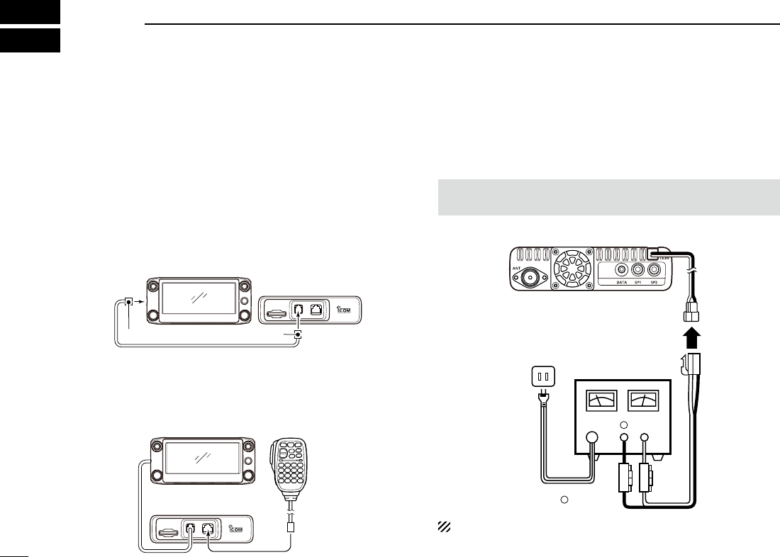
New2001
79
New2001
INSTALLATION AND CONNECTIONS
8
Connect controller to main unit ■
Connect the controller to the main unit with the supplied con-
trol cable.
• The following longer cable may be required, depending on
the installation location.
OPC-440 MIC EXTENSION CABLE: 5 m (16.4 ft)
OPC-647 MIC EXTENSION CABLE: 2.5 m (8.2 ft)
OPC-1156 CONTROLLER EXTENSION CABLE: 3.5 m (11.4 ft)
SP-35 EXTERNAL SPEAKER: 2 m (6.5 ft)
SP-35L EXTERNAL SPEAKER: 3 m (9.8 ft)
SP-30 EXTERNAL SPEAKER: 2.8 m (9.1 ft)
Controller
Main unit
6-pin connector6-pin connector
Microphone connection ■
Plug in the microphone to the microphone connector on the
main unit as shown in the illustration below.
Controller
Main unit
Microphone
DC power supply connection ■
Use a 13.8 V DC power supply with at least 20 A capacity.
Connect the black DC power cable to the (–) Negative termi-
nal, and the red DC power cable to the (+) Positive terminal.
R WARNING! NEVER remove the fuse holders from the
DC power cable.
•CONNECTINGTOADCPOWERSUPPLY
⊕
−
Main unit
to an
AC
outlet
DC power
supply 13.8 V
Fuses
20 A
−
⊕Red Black
See page 83 for a car battery connection.
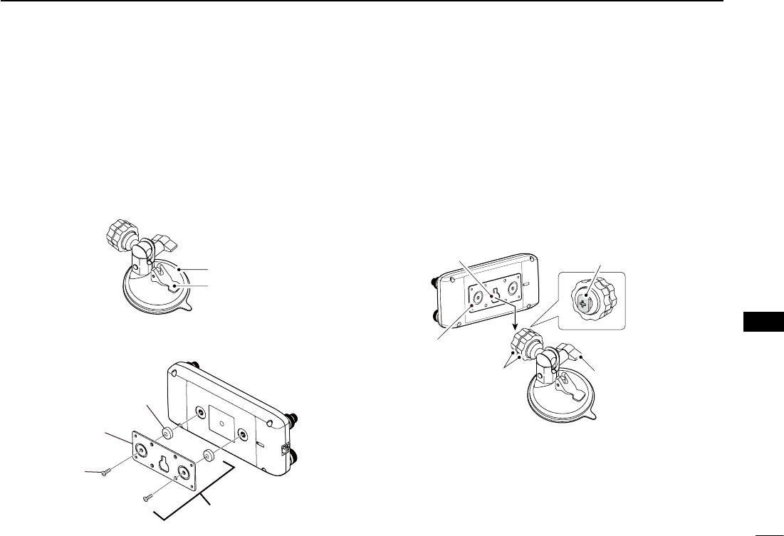
80
8
INSTALLATION AND CONNECTIONS
New2001
8
INSTALLATION AND CONNECTIONS
Remote installation ■
When installing into your vehicle D
You can install the controller on the dashboard or the console
of your vehicle with optional MBA-2 CONTROLLER BRACKET
and the MBF-1 MOUNTING BASE. (p. ??)
Attach the MBF-1 on the dashboard or the console. q
• See the MBF-1 instruction manual for details.
MBF-1 Suction pad
Base lever
Attach the MBA-2 to the controller w’s rear panel with the
supplied two screws as shown below.
Magnet
Controller
bra
cket
Screw
MBA-2
Slide e the MBA-2’s guide down over the MBF-1’s locking
head, as shown below.
• Be sure the locking head ts into the slot at the top of the
guide.
Tighten the lock knob to rsecurely attach the Controller.
Adjust the viewing angle of the remote controller, then ttighten the adjustment knob.
MBA-2
Lock knob
Adjustment knob
Locking head
(MBF-1)
Guide
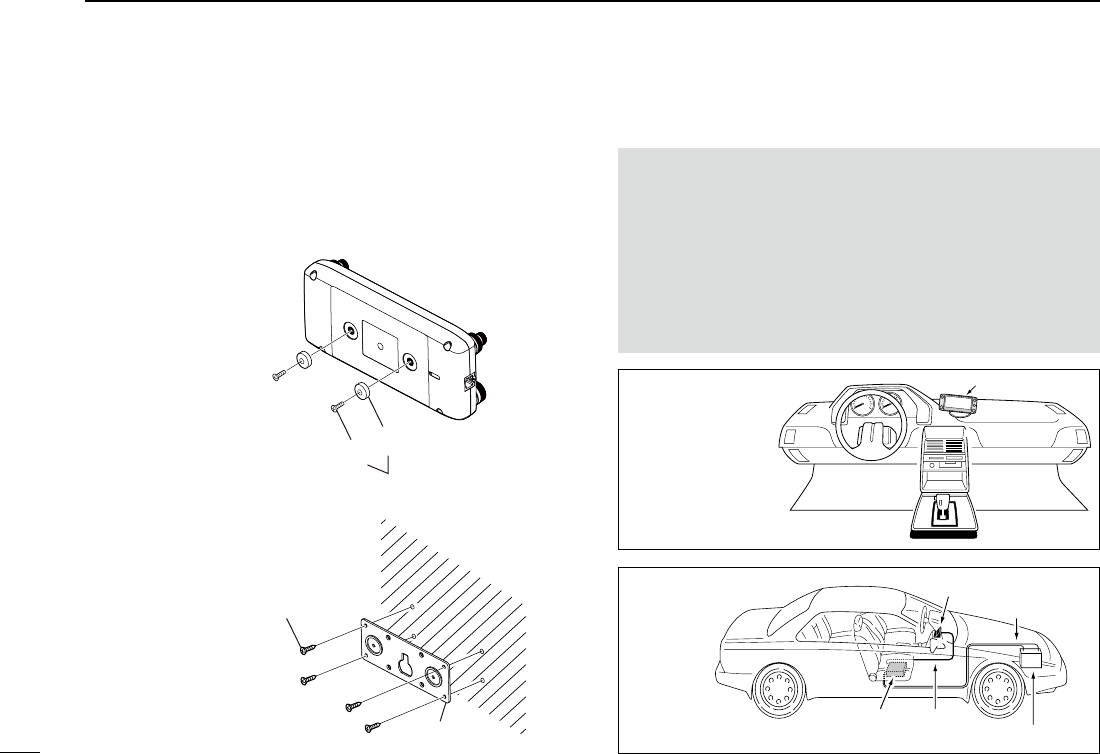
81
8INSTALLATION AND CONNECTIONS
New2001 New2001
Remote controller installation (Continued) ■When installing to a flat surface D
You can install the controller on a flat surface with the optional
MBA-2 CONTROLLER BRACKET.
When attaching the bracket onto a wall, use a self-tapping
screw* (3 mm(d)).
*Purchase separately
Magnet
Screw
Supplied with the MBA-2
Attach the magnet to the
Controller bra
cket
Screw (3 mm(d))
Purchase separately
MBA-2
When attaching the bracket
onto a wall
Installing in a vehicle ■
CAUTION: NEVER place the main unit or remote controller
where normal operation of the vehicle may be hindered or
where it could cause bodily injury.
CAUTION: NEVER place the main unit or remote controller
where air bag deployment may be obstructed.
DO NOT place the transceiver or remote controller where
hot or cold air blows directly onto it.
DO NOT place the transceiver or remote controller in direct
sunlight.
Controller
•Remotecontroller
installation
Controller
DC power cable
Battery (12V)
Controller
cable
Main
unit
•Mainunit
installation
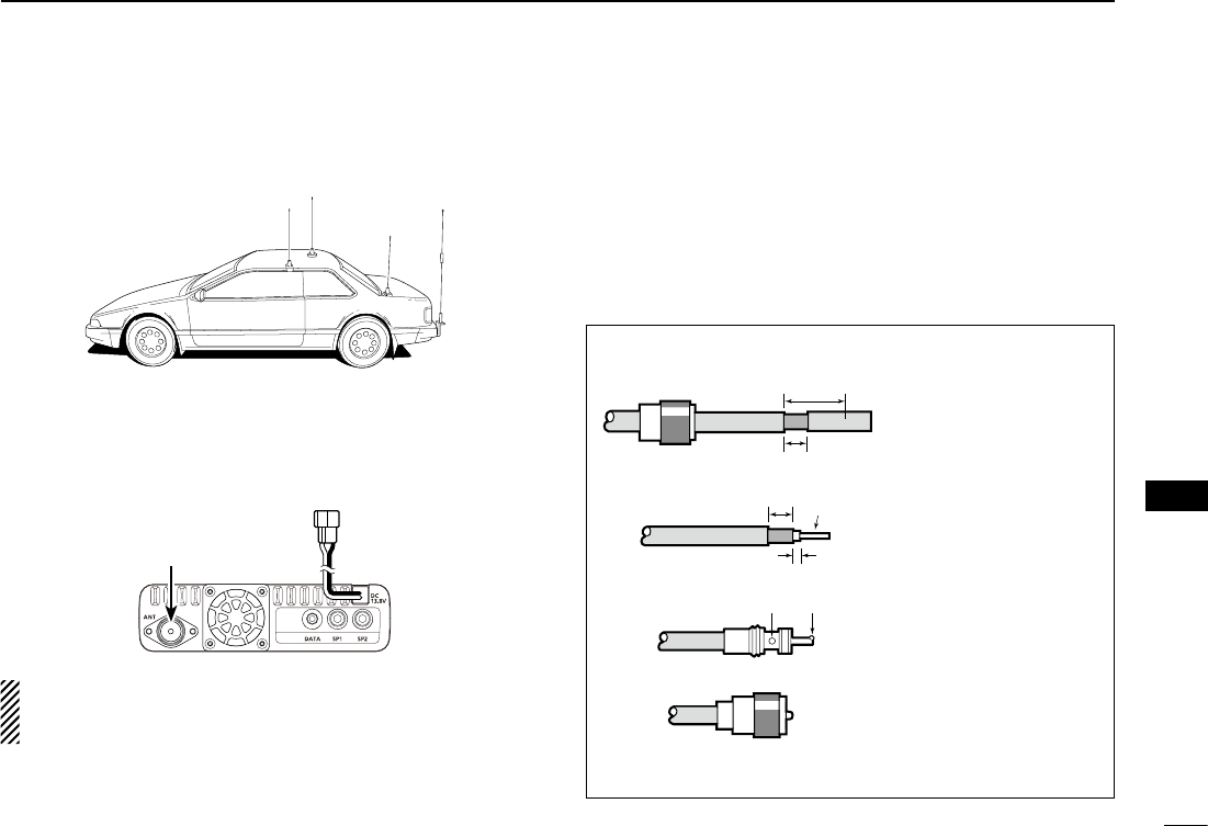
New2001
82
8
INSTALLATION AND CONNECTIONS
8
INSTALLATION AND CONNECTIONS
Antenna installation ■
•Antennalocation
w
er
q
To obtain maximum performance from the transceiver, select
a high-quality antenna and mount it in a good location.
Connect the antenna to the antenna connector on the rear ➥panel of the main unit.
Antenna connector
NOTE:
• Make the coaxial cable as short as possible.
• Be sure to seal antenna connection.
About Coaxial cable D
For radio communications, the antenna is of critically impor-
tant, along with output power and receiver sensitivity.
Select a well-matched 50 ˘ antenna and coaxial cable feed-
line. We recommend 1.5:1 or better Voltage Standing Wave
Ratio (VSWR) on your operating bands.
30 mm
10 mm (Tin)
10 mm
1–2 mm
solder solder
Tin
Coupling ring
PL-259 CONNECTOR INSTALLATION EXAMPLE
q
e
r
w
Slide the coupling ring
down. Strip the cable
jacket and tin the
shield.
Slide the connector
body on and solder it.
Screw the coupling
ring onto the connector
body.
Strip the cable as
shown to the left. Tin
the center conductor.
30 mm (1.18 in) 10 mm (0.39 in) 1–2 mm (0.04–0.08 in)
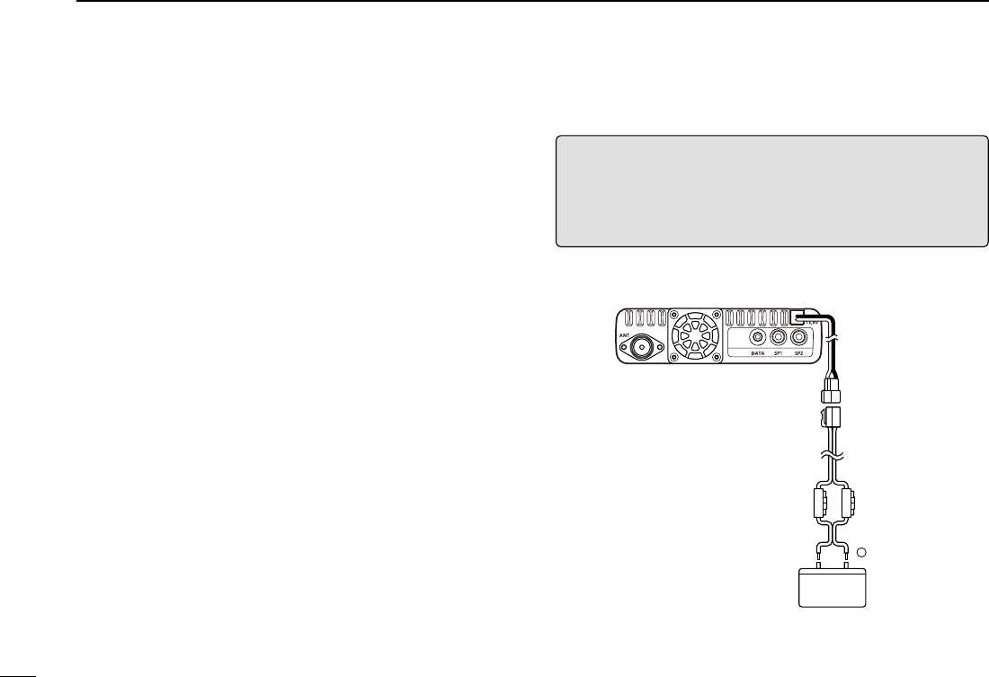
83
8INSTALLATION AND CONNECTIONS
New2001 New2001
RWARNING!
• NEVER remove the fuses from the cable connecting the
transceiver to a power source, such as a car battery.
• NEVER connect the transceiver directly to a 24 V battery.
The transceiver may not receive well on some frequencies
when installed in a hybrid vehicle, or any type of electric ve-
hicle (fuel cell vehicle). This is because vehicle’s electric com-
ponents such as the inverter system generate a lot of electric
noise.
• DO NOT use a cigarette lighter socket as a power source
when operating in a vehicle. The plug may cause voltage
drops and ignition noise may be superimposed onto transmit
or receive audio.
• Use a rubber grommet when passing the DC power cable
through a metal plate to prevent a short circuit.
RWARNING! (About DC power supply)
• Make sure DC power cable polarity is correct.
Red: Positive + terminal
Black: Negative – terminal
• DO NOT pull or bend the DC power cable.
Batteryconnection ■
Blac
k
−
Fuse
holders
⊕ Red
12 V
battery
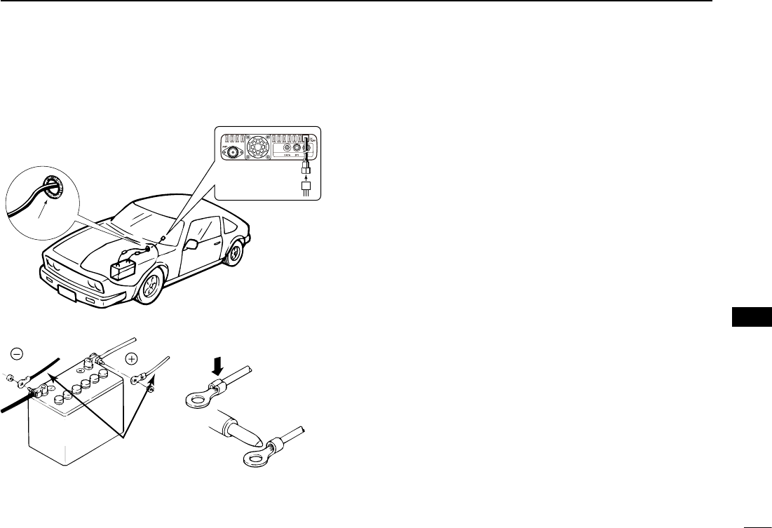
New2001
84
8
INSTALLATION AND CONNECTIONS
8
INSTALLATION AND CONNECTIONS
CONNECTING A VEHICLE BATTERY
NOTE: Use terminals for
the cable connections.
Crimp
Solder
Supplied
DC power cable
red
black
12 V
battery
Grommet
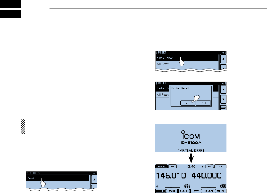
85
New2001New2001
MAINTENANCE
9New2001
Resetting ■
Occasionally, erroneous information will be displayed, for ex-
ample, when first applying power. This may be caused exter-
nally by static electricity or by other factors.
If this problem occurs, turn OFF power.
After waiting a few seconds, turn ON power again. If the prob-
lem is still there, perform a Partial reset or an All reset.
A Partial reset resets the operating settings to their default
values (VFO frequency, VFO settings, menu contents) with-
out clearing the items below:
• Memory channel contents • Scan Edge contents
• Call channel contents • Call sign memories
• Message data • DTMF memory contents
• GPS Memory contents • Repeater list
BE CAREFUL! An All reset clears all programming and
returns all settings to their factory defaults. See the Full
Instructions for details.
Partial Reset DTouch [MENU]. q Touch “Reset.” w
(Manage Memory > Others > Reset)
• If the item is not displayed, touch [∫] or [√] one or more times to
select the page.
Touch “Partial Reset.” e
Touch [YES]. r
• The transceiver displays "PARTIAL RESET," then the
partial reset is completed.
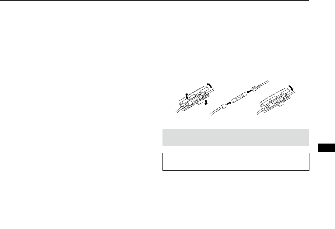
New2001
86
9
MAINTENANCE
New2001
9
MAINTENANCE
Power protect function ■
The transceiver is equipped with a protection circuit for the
power amplifier. The circuit activates when the transceiver
continuously transmit at high power, and then temperature
becomes extremely high.
In this case, the transceiver automatically displays “Over Volt-
age,” and then reduces transmit output power to low (approxi-
mately 5 W).
Spurious signals ■
Spurious signals may occur at some frequencies. These are
created in the internal circuit and does not indicate a trans-
ceiver malfunction.
You can avoid the spurious signals with the Heterodyne func-
tion. (p. ??-??)
Fuse replacement ■
A fuse is installed in each fuse holder of the supplied DC
power cable. If a fuse blows, or the transceiver stops function-
ing, track down the source of the problem if possible, repair
it and then replace the damaged fuse with a new rated one
(FGB 20 A).
R WARNING! NEVER remove the fuse holders from the
DC power cable. USE only the applicable fuses.
NOTE: Before replacing the fuse, be sure to disconnect the
DC cable from the power supply.
87
New2001New2001
INFORMATION
10
COUNTRY CODE LIST
•ISO3166-1
Country Codes Country Codes
1
2
3
4
5
6
7
8
9
10
11
12
13
14
15
16
17
Austria
Belgium
Bulgaria
Croatia
Czech Republic
Cyprus
Denmark
Estonia
Finland
France
Germany
Greece
Hungary
Iceland
Ireland
Italy
Latvia
AT
BE
BG
HR
CZ
CY
DK
EE
FI
FR
DE
GR
HU
IS
IE
IT
LV
18
19
20
21
22
23
24
25
26
27
28
29
30
31
32
33
Liechtenstein
Lithuania
Luxembourg
Malta
Netherlands
Norway
Poland
Portugal
Romania
Slovakia
Slovenia
Spain
Sweden
Switzerland
Turkey
United Kingdom
LI
LT
LU
MT
NL
NO
PL
PT
RO
SK
SI
ES
SE
CH
TR
GB
FCC INFORMATION
•FORCLASSBUNINTENTIONALRADIATORS:
This equipment has been tested and found to comply with the
limits for a Class B digital device, pursuant to part 15 of the
FCC Rules. These limits are designed to provide reasonable
protection against harmful interference in a residential instal-
lation. This equipment generates, uses and can radiate radio
frequency energy and, if not installed and used in accordance
with the instructions, may cause harmful interference to radio
communications. However, there is no guarantee that inter-
ference will not occur in a particular installation. If this equip-
ment does cause harmful interference to radio or television
reception, which can be determined by turning the equipment
off and on, the user is encouraged to try to correct the inter-
ference by one or more of the following measures:
• Reorient or relocate the receiving antenna.
• Increase the separation between the equipment and re-
ceiver.
• Connect the equipment into an outlet on a circuit different
from that to which the receiver is connected.
• Consult the dealer or an experienced radio/TV technician
for help.
CAUTION: Changes or modifications to this device, not ex-
pressly approved by Icom Inc., could void your authority to
operate this device under FCC regulations.
1-1-32 Kamiminami, Hirano-ku, Osaka 547-0003, Japan
New2001
A-7115D-2EX
Printed in Japan
© 2014 Icom Inc.
Printed on recycled paper with soy ink.
<Intended Country of Use>
■ AT ■ BE ■ CY ■ CZ ■ DK ■ EE
■ FI ■ FR ■ DE ■ GR ■ HU ■ IE
■ IT ■ LV ■ LT ■ LU ■ MT ■ NL
■ PL ■ PT ■ SK ■ SI ■ ES ■ SE
■ GB ■ IS ■ LI ■ NO ■ CH ■ BG
■ RO ■ TR ■ HR
#02 EUR-01
<Intended Country of Use>
■ AT ■ BE ■ CY ■ CZ ■ DK ■ EE
■ FI ■ FR ■ DE ■ GR ■ HU ■ IE
■ IT ■ LV ■ LT ■ LU ■ MT ■ NL
■ PL ■ PT ■ SK ■ SI ■ ES ■ SE
■ GB ■ IS ■ LI ■ NO ■ CH ■ BG
■
RO
■
TR
■
HR
#03 ITR-01
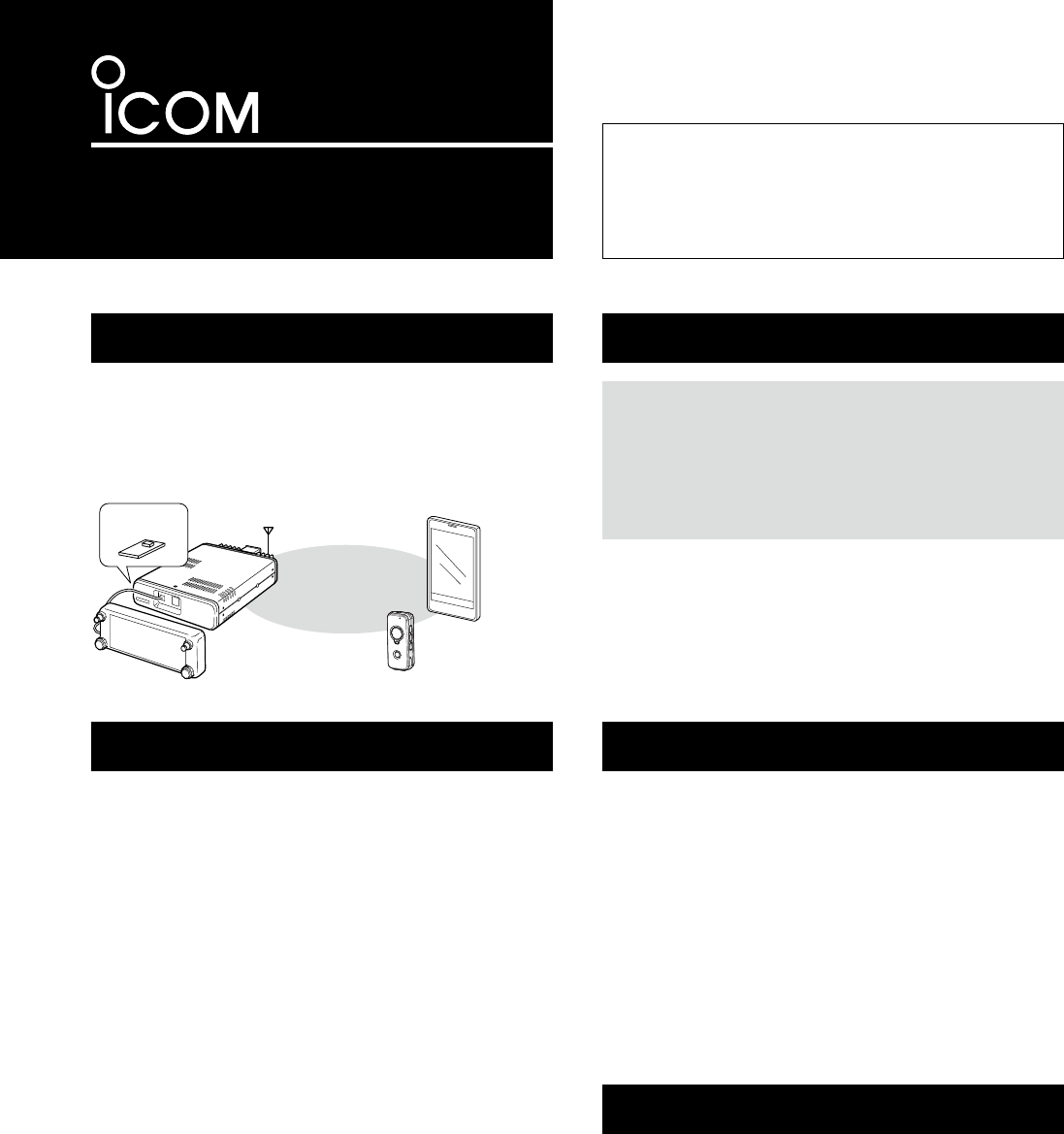
INSTRUCTIONS
Bluetooth® UNIT
UT-133
Thank you for purchasing the UT-133
Bluetooth®
UNIT
.
Installing the UT-133 in a transceiver allows you to
use a variety of Bluetooth® devices.
Please read this instructions carefully and complete-
ly before installing the UT-133.
Icom, Icom Inc. and the Icom logo are registered trademarks of Icom
Incorporated (Japan) in Japan, the United States, the United King-
dom, Germany, France, Spain, Russia and/or other countries.
The Bluetooth® work mark and logos are registered trademarks
owned by Bluetooth SIG, Inc. and any use of such marks by Icom
inc. is under license.
All other products or brands are registered trademarks or trade-
marks of their respective holders.
About the UT-133
The UT-133 is a Bluetooth
®
unit to be installed in a trans-
ceiver to communicate with other Bluetooth
®
devices.
Please refer to the transceiver’s instruction manual for de-
tails regarding installation and use of the UT-133 with the
transceiver.
Precautions
When you use a Bluetooth
®
device, pay attention to follow-
ing:
Bluetooth
®
devices operate on the 2.4 GHz band.
The 2.4 GHz band is also used by other devices, such as
wireless LAN products, microwave ovens, RFID systems,
amateur radio stations, and so on.
When using a transceiver with the UT-133 installed and
turned ON near such devices, interference may occur, caus-
ing a decrease in communication speed, and an unstable
connection.
In such cases, use the transceiver with the UT-133 away
from the other devices, or stop using those devices.
Electromagnetic Interference
The Bluetooth
®
communication range may vary, depending
on the environment in which the device operates. Micro-
wave ovens or wireless LAN may cause an interference.
In that case, stop using those devices or move away the
Bluetooth
®
device from the other devices.
This Bluetooth
®
device has a range of use. If the communi-
cation is unstable, use the device within the range.
Radio operator warnings
s$O NOT USE A TRANSCEIVER WITH THE 54 INSTALLED AND
turned ON near medical equipment, or near a person who
has a pacemaker. Radio waves from the transceiver may
cause interference, or endanger their life.
s$O NOT USE A TRANSCEIVER WITH THE 54 INSTALLED AND
turned ON near microwave ovens. Interference may occur.
s$ONOTMAKEANYCHANGESORMODIlCATIONSTOTHEUNIT
DO NOT put anything on top of the unit, before installing.
DO NOT drop, impact or vibrate the unit, before installing.
This may damage to the unit.
You may not be able to use some Bluetooth
®
device’s func-
tion, even if the unit is installed.
Bluetooth®
UT-133
Transceiver VS-3
Android
®
device
(third party)
Specifications
s"LUETOOTH
®
version: Bluetooth
®
Version 3.0
s4RANSMISSION/UTPUT #LASS
s3UPPORTEDPROlLES (&0(30300
s4HEMAXIMUMNUMBEROFPAIRED"LUETOOTH
®
devices:
8 devices*
* You can pair with up to 8 headsets and
data devices. The 8 paired devices can-
not be all headsets or all data devices.
s$IMENSIONS 7X(X$MM
7X(X$INCH
s7EIGHT GOZAPPROXIMATELY
s$EVICE.AME )COM"4DEFAULTVALUE
s0ASSKEY FOURZEROS
4HE SPECIlCATIONS ARE SUBJECT TO CHANGE WITHOUT NOTICE OR
obligations.

A-7142W-1EX
© 2014 Icom Inc.
+AMIMINAMI(IRANOKU/SAKA*APAN
FCC and IC information
s&/2#,!33"5.).4%.4)/.!,2!$)!4/23
This equipment has been tested and found to comply with
THELIMITSFORA#LASS"DIGITALDEVICEPURSUANTTOPARTOF
the FCC Rules. These limits are designed to provide reason-
able protection against harmful interference in a residential
installation. This equipment generates, uses and can radiate
radio frequency energy and, if not installed and used in ac-
cordance with the instructions, may cause harmful interfer-
ence to radio communications. However, there is no guaran-
tee that interference will not occur in a particular installation.
If this equipment does cause harmful interference to radio or
television reception, which can be determined by turning the
equipment off and on, the user is encouraged to try to correct
the interference by one or more of the following measures:
s2EORIENTORRELOCATETHERECEIVINGANTENNA
s)NCREASETHESEPARATIONBETWEENTHEEQUIPMENTANDRE-
ceiver.
s#ONNECTTHEEQUIPMENTINTOANOUTLETONACIRCUITDIFFER-
ent from that to which the receiver is connected.
s#ONSULT THE DEALER OR AN EXPERIENCED RADIO46 TECHNI-
cian for help.
#!54)/.#HANGESORMODIlCATIONSTOTHISDEVICENOTEX-
pressly approved by Icom Inc., could void your authority to
operate this device under FCC regulations.
4HISDEVICECOMPLIESWITH0ARTOF&##AND)NDUSTRY#AN-
ADALICENCEEXEMPT233STANDARDS/PERATIONISSUBJECTTO
the following two conditions: (1) this device may not cause in-
terference, and (2) this device must accept any interference,
including interference that may cause undesired operation
of the device.
This transmitter must not be co-located or operated in con-
JUNCTIONWITHANYOTHERANTENNAORTRANSMITTER
CAN ICES-3 (B)
,EPR£SENTAPPAREILESTCONFORMEAUXLAPARTIEDESRÞGLES
DELA&##ET#.2Dg)NDUSTRIE#ANADAAPPLICABLESAUXAPPAR-
EILSRADIOEXEMPTSDELICENCE,gEXPLOITATIONESTAUTORIS£EAUX
DEUXCONDITIONSSUIVANTESLgAPPAREILNEDOITPASPRODUIRE
de brouillage, et (2) l'utilisateur de l'appareil doit accepter
tout brouillage radioélectrique subi, même si le brouillage est
susceptible d'en compromettre le fonctionnement.
Cet émetteur ne doit pas être co-localisé ou fonctionner en
CONJONCTIONAVECUNEAUTREANTENNEOU£METTEUR
NMB-3 (B)
s&OR-OBILE5SE
4HIS EQUIPMENT COMPLIES WITH &##)# RADIATION EXPOSURE
limits set forth for an uncontrolled environment and meets
THE &## RADIO FREQUENCY 2& %XPOSURE 'UIDELINES AND
233OFTHE)#RADIOFREQUENCY2&%XPOSURERULES4HIS
equipment has very low levels of RF energy that it deemed
TOCOMPLYWITHOUTMAXIMUMPERMISSIVEEXPOSUREEVALUATION
(MPE).
#ET £QUIPEMENT EST CONFORME AUX LIMITES DEXPOSITION AUX
rayonnements énoncées pour un environnement non contrôlé
ETRESPECTELESRÞGLES LES RADIO£LECTRIQUES 2&DELA&##
lignes directrices d’EXPOSITIONETDEXPOSITIONAUXFR£QUENC-
es radioélectriques (RF) CNR-102 de l’IC. Cet équipement
£METUNE£NERGIE2&TRÞSFAIBLEQUIESTCONSID£R£ECONFORME
SANS£VALUATIONDELEXPOSITIONMAXIMALEAUTORIS£E
s&OR0ORTABLE5SE
4HIS EQUIPMENT COMPLIES WITH &##)# RADIATION EXPOSURE
limits set forth for an uncontrolled environment and meets
THE &## RADIO FREQUENCY 2& %XPOSURE 'UIDELINES AND
233OFTHE)#RADIOFREQUENCY2&%XPOSURERULES4HIS
equipment has very low levels of RF energy that are deemed
TOCOMPLYWITHOUTTESTINGOFSPECIlCABSORPTIONRATIO3!2
#ET £QUIPEMENT EST CONFORME AUX LIMITES DEXPOSITION AUX
rayonnements énoncées pour un environnement non contrôlé
ETRESPECTELESRÞGLES LES RADIO£LECTRIQUES 2&DELA&##
lignes directrices d’EXPOSITIONETDEXPOSITIONAUXFR£QUENCES
radioélectriques (RF) CNR-102 de l’IC. Cet équipement émet
UNE£NERGIE2&TRÞSFAIBLEQUIESTCONSID£R£ECONFORMESANS
£VALUATIONDUD£BITDABSORPTIONSP£CIlQUE$!3
Versions of the UT-133 which display the “CE”
symbol on the serial number label, comply with
the essential requirements of the Radio and
Telecommunications Terminal Equipment Di-
RECTIVE%#ANDTHERESTRICTIONOFTHE
use of certain hazardous substances in electri-
CALANDELECTRONICEQUIPMENT$IRECTIVE
EU.
You can get the DOC (Declaration Of Conformity) from your
nearest Icom dealer. See the Icom website for details of your
nearest dealer.
HTTPWWWICOMCOJPWORLD
About CE
After installing the UT-133, place the FCC/IC ID label on the
outside of the transceiver.