ICOM orporated 349500 VHF Marine Transceiver User Manual
ICOM Incorporated VHF Marine Transceiver
UserManual.wiki
>
ICOM orporated
>
349500 User Manual
>
User Manual
Contents
1.
User Manual
2.
Updated Manual
3.
User Manual_Updated
User Manual
Navigation menu
Upload a User Manual
Namespaces
Wiki Guide
HTML
PDF
Info
Views
User Manual
Discussion / Help
Navigation
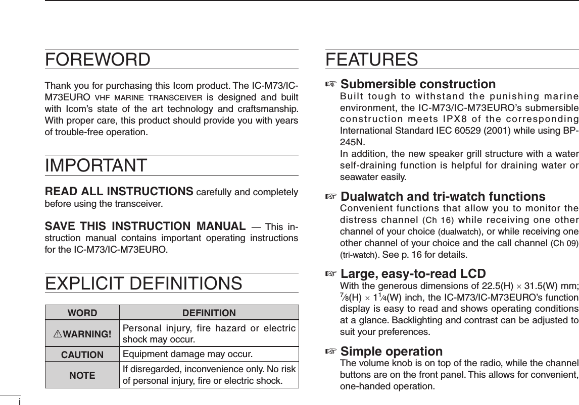
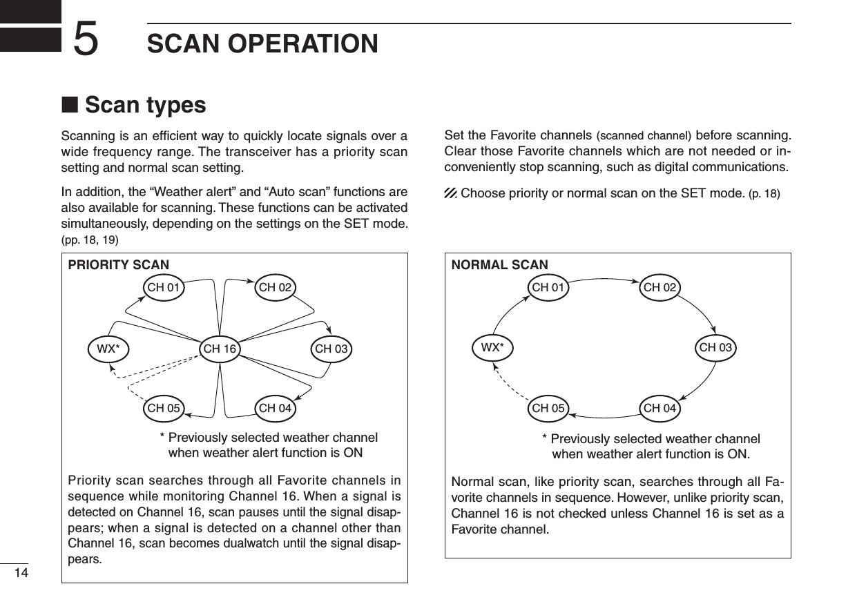
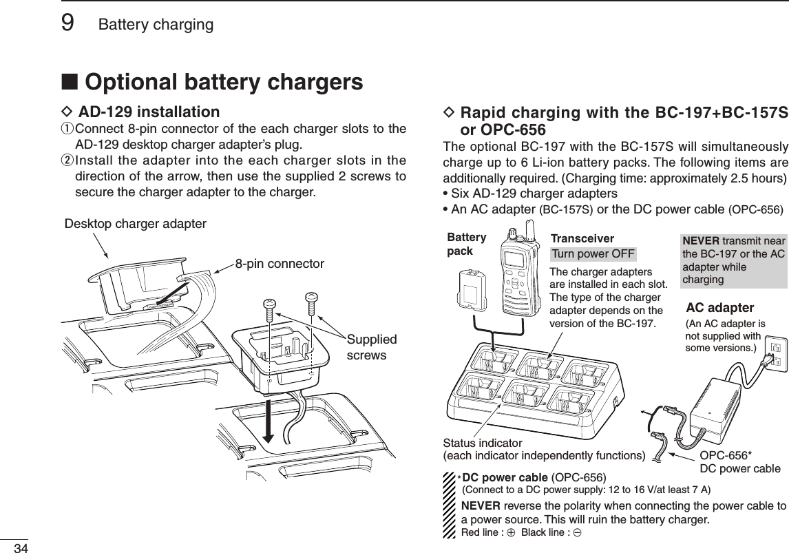
![4PANEL DESCRIPTION3■ Front, top and side panelsqweytrMicrophone!2!1!0ouiSpeakerFunctiondisplay(p. 6)q VOLUME CONTROL [VOL] Turns power ON and adjusts the audio level.w PTT SWITCH [PTT] Hold down to transmit; release to receive.e MONITOR KEY [] while held down. (p. 10) Y]/Z]. (p. 11) the SET mode. (p. 17)r CHANNEL16KEY[16/C] (p. 7) (p. 7) Enters call channel write mode when the call channel is selected and this key is held down for 3 seconds. (p. 10)t FUNCTION KEY [F] (p. 7) 1 second. (p. 7)y SCANKEY[SCAN•DUAL] (pp. 14, 15) (p. 16)](https://usermanual.wiki/ICOM-orporated/349500.User-Manual/User-Guide-1892243-Page-12.png)
,[CH](IC-73EURO) channel* when pushed. (p. 8) group when held down for 1 second. (p. 8) - The function display shows which channel group is active. channel when the priority channel or the call channel is selected. *Available with the U.S.A. and EXP versions only. NOTE: [CH/WX•U/I/C] and [CH] write as [CH/WX•U/I/C] in this instruction manual.i CHANNEL UP/DOWN KEYS [Y]/[Z] (pp. 7–9) (p. 17) ]. (p. 17) direction during scan. (p. 15)o TRANSMITPOWER/LOCKKEY[H/L•LOCK] (p. 9) second. (p. 10)!0 FAVORITE(TAG)KEY[FAV•★] channels, while ignoring untagged channels, in a channel group. (p. 8) the displayed channel. (p. 8) set all Favorite (TAG) channels in the selected channel group. (p. 8)!1 SPEAKER-MICROPHONE CONNECTOR [SP MIC] Connects the optional external speaker-microphone or headset. NOTE: Attach the [SP MIC] cap when the optional speaker-microphone or headset is not used.!2 ANTENNA CONNECTOR Connects the supplied antenna.](https://usermanual.wiki/ICOM-orporated/349500.User-Manual/User-Guide-1892243-Page-13.png)
![8BASIC OPERATION4■ Channel selectionIMPORTANT!: Prior to using the transceiver for the first time, fully charge the battery pack. This will help maxi-mize the capability and life of the battery. To avoid dam-age to the transceiver, turn the radio OFF while charging.DChannel16Channel 16 (Distress channel) is used for establishing initial contact with another station and for emergency communica-tions. Channel 16 is automatically monitored during both du-alwatch and tri-watch. While standing by, you must monitor Channel 16.q Push [16•9] to select Channel 16.w Push [CH/WX•U/I/C] to return to the condition before selecting Channel 16, or push [Y]/[Z] to select the operating channel.PushD Channel 9 (Call channel)Channel 9 is the leisure-use call channel. Each regular channel group has separate call channels. In addition, the call channel is monitored during tri-watch. The call channels can be re-programmed (p. 10) and may be used to store your most often used channels in each channel group for quick recall.q Hold down [16•9] for 1 second to select the call channel. programming” on p. 10 for details.w Push [CH/WX•U/I/C] to return to the condition before selecting Channel 9 (call channel), or push [Y]/[Z] to select the operating channel.Hold downfor 1 sec.](https://usermanual.wiki/ICOM-orporated/349500.User-Manual/User-Guide-1892243-Page-16.png)
![94BASIC OPERATION12345678910111213141516D U.S.A., International, Canadian and ATIS channelsThe IC-M73/IC-M73EURO have U.S.A.*1, International, Canadian*2 and ATIS*3 channels. You must select the proper channels for the operating area.*1U.S.A., EXP, China and U.K. versions only*2U.S.A and EXP versions only.*3German and Holland versions only.q Push [CH/WX•U/I/C] to select the regular channel. [CH/WX•U/I/C] again.w Push [Y]/[Z] to select a channel. e To change the channel group, hold down [CH/WX•U/I/C] for 1 second. For U.K. versionU.S.A. channelsInternational channelsHold downfor 1 sec.Hold downfor 1 sec.Hold down for 1 sec.Hold downfor 1 sec.Hold downfor 1 sec.For German and Holland versionsFor U.S.A. and China versionsInternational channelsInternational channelsU.S.A. channelsATIS channelsCanadian channels](https://usermanual.wiki/ICOM-orporated/349500.User-Manual/User-Guide-1892243-Page-17.png)
![104BASIC OPERATIOND Weather channelsThe IC-M73 has 10 weather channels. They are used for monitoring NOAA (National Oceanographic and Atmospheric Ad-ministration) broadcasts (reception of weather channels possible in U.S.A. only).q Push [CH/WX•U/I/C] to select the weather channel group.w Push [Y]/[Z] to select a weather channel.e Push [CH/WX•U/I/C] to return to the condition before selecting the weather channel group.✔ CONVENIENT!The IC-M73 can detect a weather alert tone on the selected weather channel while in another channel (when the power save function is turned ON) or during scanning. See the “SET mode items” on p. 18 for details.](https://usermanual.wiki/ICOM-orporated/349500.User-Manual/User-Guide-1892243-Page-18.png)
![114BASIC OPERATION12345678910111213141516■ Receiving and transmittingCAUTION: Transmitting without an antenna may damage the transceiver.q Rotate [VOL] clockwise to turn power ON. [16/•] to skip the opening comment indication.w Set the volume and squelch level. ➥ Push [], and push [Z] to open the squelch. ➥ Rotate [VOL] to set the volume level. ➥ Push [], and push [Y]/[Z] to set the squelch level.e Push [Y]/[Z] to select the desired channel.- When receiving a signal, “ ” indicator appears while audio is emitted from the speaker.- Further adjustment of [VOL] may be necessary at this point.r Push [H/L•LOCK] to select the output power, if necessary.- “LOW” appears when low power is selected; “MID” appears when middle power is selected; no indication when high power is selected.- Choose low or mid. power to conserve battery power, choose high power for longer distance communications.- Some channels are for low power only.t Hold down [PTT] to transmit, and speak into the microphone.- The transmit indicator appears while transmitting.- Channel 70 cannot be used for transmission.y Release [PTT] to receive.IMPORTANT: To maximize the readability of your trans-mitted signal, pause a second after pushing [PTT], hold the microphone 5 to 10 cm (2 to 4 inches) from your mouth, and speak into the microphone using a normal voice level.NOTE: The transceiver has a power save function to con-serve the battery power. The power save function acti-vates automatically when no signal is received for 5 sec-onds.To prevent accidental prolonged transmission, etc., the IC-M73 has a time-out timer function. This timer cuts a transmission OFF after 5 min. of continuous transmission.q Power ONw Set volumew Set the squelch levelw Set the squelch levele Select the channelr Set output powert Push to transmity Release to receiveMicrophoneSpeaker](https://usermanual.wiki/ICOM-orporated/349500.User-Manual/User-Guide-1892243-Page-19.png)
![124BASIC OPERATION12■ Call channel programmingThe call channel key is used to select Channel 9 by default, however, you can program your most often-used channel in each channel group for quick recall.q Hold down [CH/WX•U/I/C] for 1 second several times to select the desired channel group (USA, INT, CAN) to be programmed.w Hold down [16•9] for 1 second to select the call channel. e Hold down [16•9] a gain fo r 3 seconds (until a long beep changes to 2 short beeps) to enter call channel programming condition. blinks.r Push [Y]/[Z] to select the desired channel.t Push [16•9] to program the displayed channel as the call channel. ■ Lock functionThis function electronically locks all keys (except for [PTT], [] and [H/L•LOCK]) to prevent accidental channel changes and function access.➥ Push [H/L•LOCK] for 1 second to turn the lock function ON or OFF.Hold downfor 1 sec.Appears while the lockfunction is in use.■ Monitor functionThe monitor function releases the noise squelch mute to check the volume level. See p. 19 for details of the monitor switch action.➥ Hold down [] for 1 second to activate the monitor func-tion. ” and “ ” appear and audio is emitted.Appears while the monitor function is in use.Hold downfor 1 sec.](https://usermanual.wiki/ICOM-orporated/349500.User-Manual/User-Guide-1892243-Page-20.png)
![134BASIC OPERATION12345678910111213141516■ Adjusting the squelch levelTo adjust the IC-M73/IC-M73EURO’s squelch level, use the [Y]/[Z] keys as desired below. In order to receive signals properly, as well as for the scan to function effectively, the squelch must be adjusted to the proper level.q Push [], then adjust the squelch level with [Y]/[Z]. - “SQL” and the squelch level are displayed. - There are 11 squelch levels to choose from: OP is completely open; 10 is tight squelch; 1 is loose squelch level. - When no key is pushed for 5 seconds, the transceiver returns to normal condition.w Push [] again to return to normal operating mode.Push Shows the squelchlevel.Appears during squelch level adjustment■ AquaQuake water draining functionThe IC-M73/IC-M73EURO uses a new technology to clear water away from the speaker grill: AquaQuake. AquaQuake helps drain water away from the speaker housing (water that might otherwise muffle the sound coming from the speaker). The IC-M73/IC-M73EURO emits a vibrating noise when this function is being used. ➥ Hold down [F]. -less of [VOL] control setting. The transceiver never accepts a key operation while the Aqua-Quake function is activated. And this function won’t be activated when an optional speaker-microphone or headset is connected.](https://usermanual.wiki/ICOM-orporated/349500.User-Manual/User-Guide-1892243-Page-21.png)
![155SCAN OPERATION12345678910111213141516■ Setting Favorite channelsFor more efficient scanning, add desired channels as Favor-ite channels or clear the Favorite for unwanted channels.Untagged will be skipped during scanning. Favorite channels can be assigned to each channel group (USA, INT, CAN) in-dependently.q Select the desired channel to set as a Favorite channel.w Hold down [FAV•★] for 1 second to set the displayed channel as a Favorite channel. ★” appears in the function display.e To cancel the Favorite channel setting, hold down [FAV•★] for 1 second. ★” disappears.✔ Clearing All Favorite Channels in the Selected Channel GroupWhile holding down [FAV•★], turn power ON to clear all Fa-vorite channels setting in the channel group.■ Starting a scanSet the weather alert function, priority scan function, scan resume timer and auto scan function in advance, using the SET mode. (pp. 18, 19)q Make sure the desired channel group (e.g., USA, CAN, INT) is selected. Move between channel groups by repeatedly pushing [CH/WX•U/I/C] for 1 second at a time. weather channel with [CH/WX•U/I/C] and [Y]/[Z].w Push [SCAN•DUAL] to start priority or normal scan. When a signal is received, scan pauses until the signal disappears or resumes after pausing 5 seconds according to scan resume timer setting. (Channel 16 is still monitored during priority scan.) [Y]/[Z] to check the scanning Favorite channels, change the scanning direction or resume the scan manually.e To stop the scan, push [SCAN•DUAL]. [PTT], [16•9] or [CH/WX•U/I/C] also stops the scan.Scan starts“SCAN” indication blinksPush Pushto stop the scanWhen receiving a signal, “SCAN” indica-tion blinks and audio is emitted.[Example]: Starting a normal scan.](https://usermanual.wiki/ICOM-orporated/349500.User-Manual/User-Guide-1892243-Page-23.png)
![16DUALWATCH/TRI-WATCH6■ DescriptionDualwatch monitors Channel 16 while you are receiving another channel; tri-watch monitors Channel 16 and the call channel while receiving another channel.■ Operationq Select the desired operating channel.w Hold down [SCAN•DUAL] for 1 second to start dualwatch or tri-watch (depending on the SET mode setting; p. 19). call channel.e To cancel dualwatch/tri-watch, push [SCAN•DUAL] again.DUALWATCH/TRI-WATCH SIMULATIONDualwatchTri-watchCall channelpauses on Channel 16 until the signal disappears.watch, tri-watch becomes dualwatch until the signal dis-appears.watch, hold down [PTT].[Example]: Operating tri-watch on INT channel 07.Signal is received on the call channel.A signal receive on Channel 16 always takes priority.Tr i-watch resumes after the signal disappears.Tr i-watch starts.Hold down for 1 sec.](https://usermanual.wiki/ICOM-orporated/349500.User-Manual/User-Guide-1892243-Page-24.png)
![177FUNCTION MODE OPERATION12345678910111213141516■ About the function modeThere are 7 transceiver functions in the function mode: Play back function, Manual recording function, Automatic record-ing function, backlight function, channel naming function, opening comment entry function and ATIS code program-ming function†.†Depending on versions.D Entering the function modeq Turn power ON.w Push [F] to enter the function mode. e Push [Y]/[Z] to select the desired item.r Push [H/L•KEY] to select or decide the desired condition of the item. [H/L•KEY].t To exit the function mode, push [F].D FUNCTION MODE ITEMSPlayback function*Manual recordingfunctionAutomatic recordingfucntion Backlight functionATIS code programmingfunction†Opening commententry functionChannel namingfunction: Push [Y] : Push [Z] *Starting item†Availability may differ according to versions.](https://usermanual.wiki/ICOM-orporated/349500.User-Manual/User-Guide-1892243-Page-25.png)
![187FUNCTION MODE OPERATION■ Play back functionThis transceiver has the two voice recorders.One is the manual recording function which can record for 30 seconds, the other is the automatic recording function which can record the end of 60 seconds of the receiving sig-nal.There are three playing back mode as follow.q Push [F] to enter the function mode. w Push [H/L•KEY]to enter the play back selection mode, and then push [Y]/[Z] to select the desired play back mode from “M-PLAY,” “LAST30S,” or “LAST60S.” If there is no recorded signal in the transceiver, “BLANK” is appeared. recorded signal. recorded signal from last 30 seconds. recorded signal.e Push [H/L•KEY] to play back the recorded signal. [H/L•KEY] again.Blinks while playbacking.Playback mode appears.“BLANK” is appeared when the transceiver has no recorded signal.dingdingdingPlaying back 30 seconds (maximum).Select “M-PLAY”Select “LAST60S”Select “LAST30S”Not playing back.Playing back for 60 seconds (maximum).Playing back for 30 seconds (maximum).](https://usermanual.wiki/ICOM-orporated/349500.User-Manual/User-Guide-1892243-Page-26.png)
![197FUNCTION MODE OPERATION12345678910111213141516■ Manual recording functionYou can record the received signal whenever you want by using the manual recording function.This function can record the receiving signal for 30 seconds.q Push [F] to enter the function mode, and then push [Y]/[Z] to select the manual recording function. w Push [H/L•KEY]to star t to record the receiving signal. stop after 30 seconds.e The recording will automatically stop after 30 seconds. [F] to stop the recording.Manual recordingmode appears.“REC” is appeared while recording.Example— Manual recording[Less than 30 seconds][More than 30 seconds]20 seconds30 secondsWhen receiving signal within 30 seconds, this function records the all contents.After passing 30 seconds from starting the manual recording, the recording will be automatically stopped.These contentswon’t be recorded.Tu rn the manualrecording ON.Tu rn the manualrecording ON.Tu rn the manualrecording OFF.Stops recordingautomatically.](https://usermanual.wiki/ICOM-orporated/349500.User-Manual/User-Guide-1892243-Page-27.png)
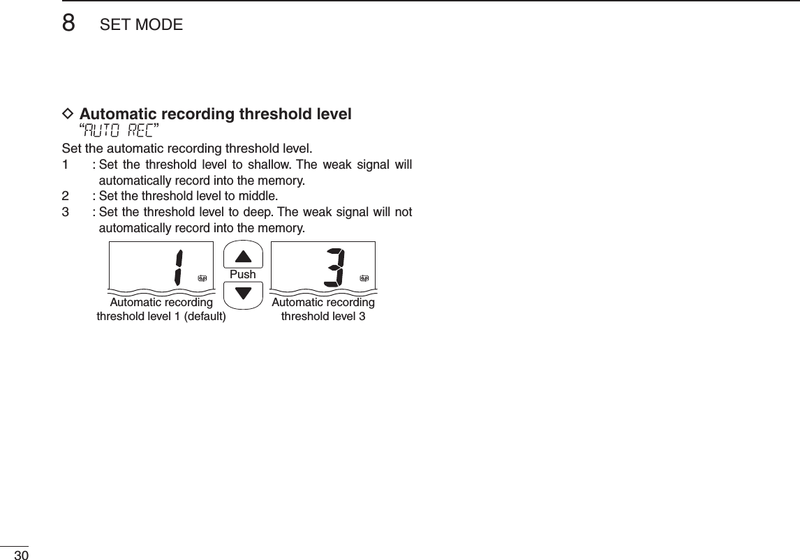
![207FUNCTION MODE OPERATION■ Automatic recording functionWhen this function turns ON, the transceiver automatically records the receiving signal into the memory.A maximum recording length of 60 seconds can be recorded into the memory.for details.q Push [F] to enter the function mode, and then push [Y]/[Z] to select the automatic recording function. w Push [H/L•KEY]to turn the function ON or OFF. appeared. automatically cancelled after pushing [H/L•KEY].e When the transceiver receives a signal, it will automatically re-automatically re-cord the receiving signal into the memory. stop when the receiving signal disappears.Automatic recordingmode appears.“REC” is appeared while recording.Automatic recording icon is appeared.• Example— Automatic recording[Less than 60 seconds][More than 60 seconds]40 seconds60 secondsWhen receiving signal within 60 seconds, this function records the all contents.After passing 60 seconds from starting automatic recording, this function records the 60 seconds before stopping the record.These contentswon’t be recorded.Starts recordingStarts recordingStops recordingStops recording](https://usermanual.wiki/ICOM-orporated/349500.User-Manual/User-Guide-1892243-Page-28.png)
![217FUNCTION MODE OPERATION12345678910111213141516■ Backlighting functionThis function is convenient for nighttime operation. The back-lighting can be turned OFF in the SET mode. (p. 19)➥ Push any key other than [PTT] to turn the backlighting ON. inactivity.q Push [F] to enter the function mode, and then push [Y]/[Z] to select the backlighting function. w Push [H/L•KEY]to turn the function ON or OFF. cancelled after pushing [H/L•KEY].e Push any key other than [PTT] to turn the backlighting ON. inactivity. ■ Channel naming functionThe IC-M73/IC-M73EURO has a capability to assign up to 10-character channel names for each operating channel, including each weather channel. This provides easy recognition of channel usage, or station names, etc.When shipped from the factory, the IC-M73/IC-M73EURO is programmed with default names for each VHF marine channel. These defaults can be changed, if desired.D Available characters(=)(4)(D)(N)(X)(h)(r)(�)(5)(E)(O)(Y)(i)(s)(+)(6)(F)(P)(Z)(j)(t)(7)(G)(Q)(a)(k)(u)(,)(8)(H)(R)(b)(l)(v)(/)(9)(I)(S)(c)(m)(w)(0)(Space)(J)(T)(d)(n)(x)(1)(A)(K)(U)(e)(o)(y)(2)(B)(L)(V)(f)(p)(z)(3)(C)(M)(W)(g)(q)(–)Backlight modeappears.](https://usermanual.wiki/ICOM-orporated/349500.User-Manual/User-Guide-1892243-Page-29.png)
![227FUNCTION MODE OPERATIOND Channel name programmingq Push [Y]/[Z] to select a channel to program. [CH/WX•U/I/C] for 1 second to select a channel group, if necessary.w Push [F] to enter the function mode, and then push [Y]/[Z] to select the channel naming function. e Push [H/L•KEY]to edit the channel name. programmed name blinks.r Push [Y]/[Z] to select a character.t Push [CH/WX•U/I/C] to move to the right; then push [Y]/[Z] to select a character. [SCAN•DUAL], moves to lefty Continue until the desired charac-ters have been selected, then push [H/L•KEY] to return to normal opera-tion.■ Opening comment entry functionThe IC-M73/IC-M73EURO has a capability to assign up to 10-character opening comments.You may replace the factory-set opening comment with a comment of your own. The opening comment appears each time the IC-M73/IC-M73EURO is powered ON. The comment may be up to 16 characters long.You can use same characters as “Channel naming function.” (p. 22)D Opening comment programmingq Push [F] to enter the function mode, and then push [Y]/[Z] to select the channel naming function. w Push [H/L•KEY]to edit the opening comment. programmed comment blinks.](https://usermanual.wiki/ICOM-orporated/349500.User-Manual/User-Guide-1892243-Page-30.png)
![237FUNCTION MODE OPERATION12345678910111213141516e Push [Y]/[Z] to select a character.r Push [CH/WX•U/I/C] to move to the right; then push [Y]/[Z] to select a character. [SCAN•DUAL], moves to leftt Continue until the desired charac-ters have been selected, then push [H/L•KEY] to return to normal op-eration.The programmed opening comment is briefly displayed or scrolled when the transceiver is powered ON.However, the opening comment in-dication can be skipped by pushing [16•9].■ ATIS code programmingThe 10-digit ATIS code can be programmed and confirmed with the following operation.The ATIS code programming is not necessary and confi rmation can only be performed when the ATIS code has been programmed by your dealer. The code programming can be performed 1 time only, when the code has not been programmed by your dealer.D Opening comment programmingq Push [F] to enter the function mode, and then push [Y]/[Z] to select the ATIS code program-ming function. w Push [H/L•KEY]to edit the ATIS code. character of the code blinks.](https://usermanual.wiki/ICOM-orporated/349500.User-Manual/User-Guide-1892243-Page-31.png)
![247FUNCTION MODE OPERATIONe Push [Y]/[Z] to select a char-acter.r Push [CH/WX•U/I/C] to move to the right; then push [Y]/[Z] to select a character. [SCAN•DUAL], moves to leftt After inputting the 10-digit ATIS code, push [H/L•KEY] to write the code into the memory, then return to normal operation.D ATIS code confirmation (When the ATIS code has been programmed)q Push [F] to enter the function mode, and then push [Y]/[Z] to select the ATIS code programming function. w Push [H/L•KEY]to confirm the ATIS code. scrolls at the channel comment indicator.e Push [H/L•KEY]to return to normal operation.ScrollsScrolls](https://usermanual.wiki/ICOM-orporated/349500.User-Manual/User-Guide-1892243-Page-32.png)
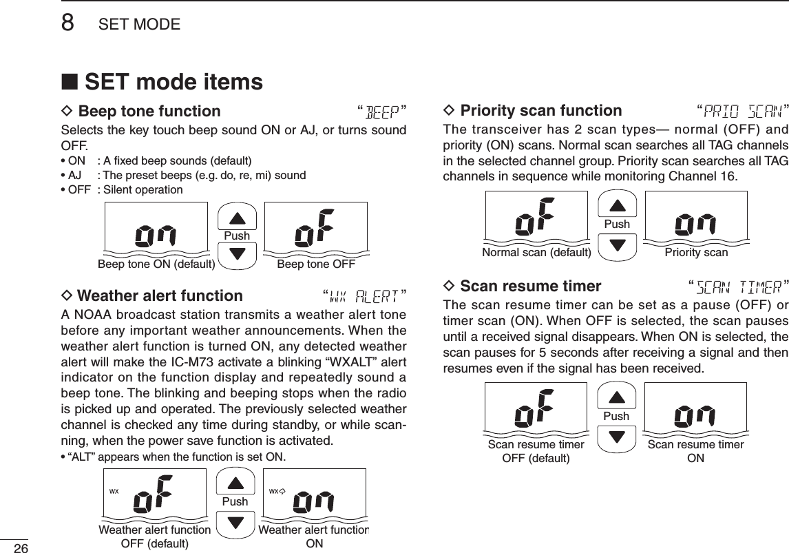
![258SET MODE12345678910111213141516■ SET mode programmingSET mode is used to change the condition of 17 transceiver functions: beep tone function, weather alert function, scan type, scan resume timer, auto scan function, dual/tri-watch function, monitor key action, backlighting function, LCD con-trast selection, auto power save function, Scroll type selec-tion, Scroll speed selection, RX noise cancel function, TX noise function, RX bass boost function, TX bass boost func-tion and automatic recording threshold level selection.D SET mode operationq Turn power OFF.w While holding down [], turn power ON to enter the SET mode. e Push [], or push [ ] and [Y]/[Z] to select the de-sired item.r Push [Y]/[Z] to select the desired condition of the item.t To exit the SET mode, push [16•9].D SET MODE ITEMSBeep tone* Weather alertPriority scan Scan resume timerAuto scan start functionDual/Tri-watchMonitor keyactionDisplaybacklightLCDcontrastAutomtic recording threshold levelTX bass boostRX bass boostPower save functionScroll typeScroll speedRX noise cancelTX noise cancel: Push [ ], or while holding down [ ], push [Y]: While holding down [ ], push [Z]*Starting item](https://usermanual.wiki/ICOM-orporated/349500.User-Manual/User-Guide-1892243-Page-33.png)
![278SET MODE12345678910111213141516D Auto scan function “”The auto scan function starts the desired scan automatically when no signal is received, and no operation is performed for 30 secondsPushAuto scan OFF (default) Auto scan OND Dual/Tri-watch function “”This item selects dual or tri-watch as desired. See p. 16 for details.PushDualwatch (default) Tr i-watchD Monitor key action “”The monitor key action cuts off the squelch function temporarily. This key action contains PUSH (Pu) or HOLD (Ho) settings as shown below.[] for 1 second, the squelch opens and emits audio. The squelch is held open while continuously holding down []. (default)[ ] for 1 second, the squelch opens and emits audio even [ ] is released. To close the squelch, push any key.PushPush setting (default) Hold settingD Backlight function “”This function is convenient for nighttime operation. The backlight can be selected from ON and OFF.[PTT] is pushed. inactivity.PushBacklight ON(default)Backlight OFF](https://usermanual.wiki/ICOM-orporated/349500.User-Manual/User-Guide-1892243-Page-35.png)
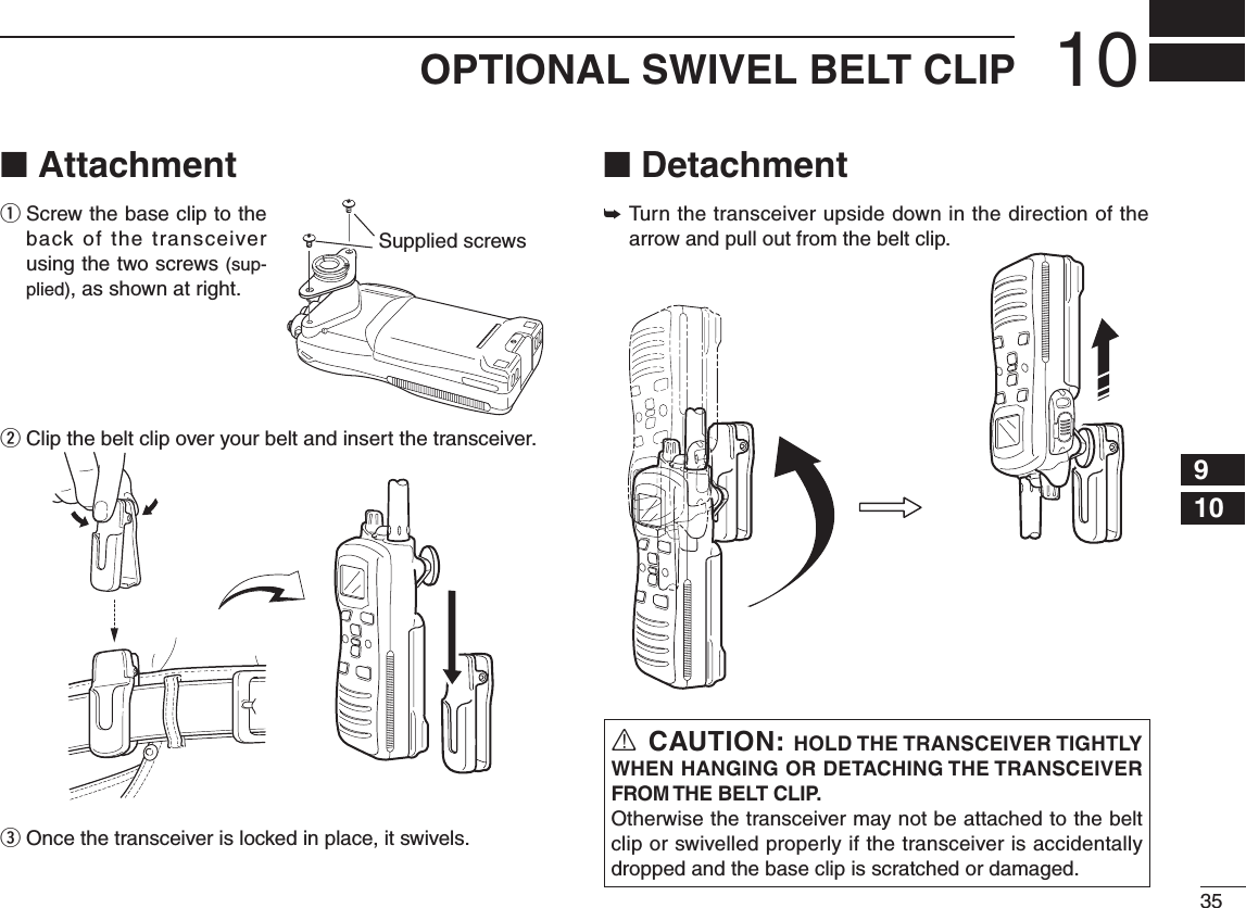
![36OPTIONAL SPEAKER-MICROPHONE11■HM-167descriptionsAlligator type clipTo attach the speaker-mic.to your shirt or collar, etc.PTT switchTransmits during push.Receives during release.MicrophoneSpeakerTu rn the transceiver power OFF when connecting the HM-167.NEVER immerse the connector in water. If the connector becomes wet, be sure to dry it BEFORE attaching it to the transceiver.NOTE: The microphone is located at the top of the speak-er-microphone, as shown in the diagram above. To maxi-mize the readability of your transmitted signal (voice), hold the microphone approx. 2.5 cm (1 inch) from your mouth, and speak in a normal voice level.■ AttachmentInsert the speaker-mic connector onto the [SP MIC] con-nector and carefully screw it tight, as shown in the diagram below. Be careful not to cross-thread the connection.Set the triangle mark to the front side.CAUTION: Attach the speaker- microphone’s connector securely to prevent accidental dropping, or water intrusion in the connector.Detaching:Pull up the cap in the direction of the arrow to detach it.Attaching:Attach the cap in the direction of the arrow completely.IMPORTANT: KEEP the transceiver’s [SP MIC] connec-tor cap attached when the speaker-microphone is not in use. Water will not get into the transceiver even if the cover is not attached; however, the terminals (pins) will become rusty, or the transceiver will function abnormally if the connector has become wet.](https://usermanual.wiki/ICOM-orporated/349500.User-Manual/User-Guide-1892243-Page-44.png)
![3712TROUBLESHOOTING12345678910111213141516PROBLEM POSSIBLE CAUSE SOLUTION REF.The transceiver does not turn ON.pp. 25–27p. 3N o s o u n d f r o m t h e speaker.[SP MIC] connector.[VOL] to set a suitable level.[16•9] and [H/L•LOCK] to drain water from the speaker.[SP MIC] connector.p. 11p. 9p. 12—Transmitting is impossible, or high power can not be selected. receive only.[H/L•LOCK] to select high power.pp. 8, 9, 31pp. 25–27—p. 9The displayed channel cannot be changed. [H/L•LOCK] for 1 second to cancel the function. p. 10Scan does not start. p. 15No beeps. SET mode.p. 18Self check error.(Temperature) +73°C; –31°F to +163°F (approx.).Turn the power ON to check if the internal temperature has returned to normal.—Self check error.(Battery voltage)more than 11 V. —Transmitting continuously while not speaking when using VOX function. [] and [H/L•LOCK] to deactivate the VOX function.p. 12p. 22“CHARGE” comment blinks pp. 25–27](https://usermanual.wiki/ICOM-orporated/349500.User-Manual/User-Guide-1892243-Page-45.png)