ICOM orporated 349500 VHF Marine Transceiver User Manual
ICOM Incorporated VHF Marine Transceiver
Contents
- 1. User Manual
- 2. Updated Manual
- 3. User Manual_Updated
User Manual

INSTRUCTION MANUAL
iM73
VHF MARINE TRANSCEIVER
This device complies with Part 15 of the FCC Rules. Opera-
tion is subject to the condition that this device does not cause
harmful interference.
iM73EURO

i
FOREWORD
Thank you for purchasing this Icom product. The IC-M73/IC-
M73EURO V H F M A R I N E T R A N S C E I V E R is designed and built
with Icom’s state of the art technology and craftsmanship.
With proper care, this product should provide you with years
of trouble-free operation.
IMPORTANT
READ ALL INSTRUCTIONS carefully and completely
before using the transceiver.
SAVE THIS INSTRUCTION MANUAL — This in-
struction manual contains important operating instructions
for the IC-M73/IC-M73EURO.
EXPLICIT DEFINITIONS
WORD DEFINITION
RWARNING! Personal injury, fire hazard or electric
shock may occur.
CAUTION Equipment damage may occur.
NOTE
If disregarded, inconvenience only. No risk
of personal injury, fire or electric shock.
FEATURES
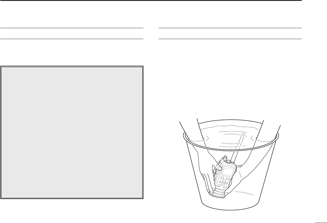
☞ Submersible construction
Built tough to withstand the punishing marine
environment, the IC-M73/IC-M73EURO’s submersible
constr uction meets IPX8 of the corresponding
International Standard IEC 60529 (2001) while using BP-
245N.
In addition, the new speaker grill structure with a water
self-draining function is helpful for draining water or
seawater easily.
☞ Dualwatch and tri-watch functions
Convenient functions that allow you to monitor the
distress channel (Ch 16) while receiving one other
channel of your choice (dualwatch), or while receiving one
other channel of your choice and the call channel (Ch 09)
(tri-watch). See p. 16 for details.
☞ Large, easy-to-read LCD
With the generous dimensions of 22.5(H) × 31.5(W) mm;
7⁄8(H) × 11⁄4(W) inch, the IC-M73/IC-M73EURO’s function
display is easy to read and shows operating conditions
at a glance. Backlighting and contrast can be adjusted to
suit your preferences.
☞ Simple operation
The volume knob is on top of the radio, while the channel
buttons are on the front panel. This allows for convenient,
one-handed operation.

ii
CLEAN THE TRANSCEIVER AND MICROPHONE THOR-
OUGHLY WITH FRESH WATER after exposure to water
including salt, otherwise, the keys and switch may become
inoperable due to salt crystallization.
RWARNING! NEVER connect the transceiver to an
AC outlet. This may pose a fire hazard or result in an electric
shock.
RWARNING! NEVER hold the transceiver so that
the antenna is closer than 2.5 cm (1 inch) from exposed parts
of the body, especially the face or eyes, while transmitting.
The transceiver will perform best if the microphone is 5 to
10 cm (2 to 4 inches) away from the lips and the transceiver is
vertical.
NEVER connect the transceiver to a power source
other than the BP-245N. Such a connection will ruin the
transceiver.
AVOID using or placing the transceiver in direct sunlight
or in areas with temperatures below –20°C (–4°F) or above
+60°C (+140°F).
KEEP the transceiver out of the reach of children.
KEEP the transceiver at least 0.9 meters (3.0 ft) away from
your vessel’s magnetic navigation compass.
MAKE SURE the flexible antenna and battery pack are
securely attached to the transceiver, and that the antenna
and battery pack are dry before attachment. Exposing
the inside of the transceiver to water will result in serious
damage to the transceiver.
BE CAREFUL! The IC-M73/IC-M73EURO employs
submersible construction (1.5 m; 4.9 ft depth for 30 min.).
However, once the transceiver has been dropped,
waterproofing cannot be guaranteed due to the fact that
the transceiver may be cracked, or the waterproof seal
damaged, etc.
For the U.S.A. only
CAUTION: Changes or modifications to this device, not
expressly approved by Icom Inc., could void your authority to
operate this device under FCC regulations.
Icom, Icom Inc. and the Icom logo are registered trademarks of Icom
Incorporated (Japan) in the United States, the United Kingdom, Germany,
France, Spain, Russia and/or other countries.
PRECAUTION

iii
RADIO OPERATOR WARNING
WARNING
Icom requires the radio operator to meet the
FCC Requirements for Radio Frequency Expo-
sure. An omnidirectional antenna with gain not
greater than 9 dBi must be mounted a mini-
mum of 5 meters (measured from the lowest
point of the antenna) vertically above the main
deck and all possible personnel. This is the minimum safe
separation distance estimated to meet all RF exposure com-
pliance requirements. This 5 meter distance is based on the
FCC Safe Maximum Permissible Exposure (MPE) distance
of 3 meters added to the height of an adult (2 meters) and is
appropriate for all vessels.
For watercraft without suitable structures, the antenna must
be mounted so as to maintain a minimum of 1 meter verti-
cally between the antenna, (measured from the lowest point
of the antenna), to the heads of all persons AND all persons
must stay outside of the 3 meter MPE radius.
Do not transmit with radio and antenna when persons are
within the MPE radius of the antenna, unless such persons
(such as driver or radio operator) are shielded from antenna
field by a grounded metallic barrier. The MPE Radius is the
minimum distance from the antenna axis that person should
maintain in order to avoid RF exposure higher than the al-
lowable MPE level set by FCC.
FAILURE TO OBSERVE THESE LIMITS MAY ALLOW
THOSE WITHIN THE MPE RADIUS TO EXPERIENCE RF
RADIATION ABSORPTION WHICH EXCEEDS THE FCC
MAXIMUM PERMISSIBLE EXPOSURE (MPE) LIMIT.
IT IS THE RESPONSIBILITY OF THE RADIO OPERATOR
TO ENSURE THAT THE MAXIMUM PERMISSIBLE EXPO-
SURE LIMITS ARE OBSERVED AT ALL TIMES DURING
RADIO TRANSMISSION. THE RADIO OPERATOR IS TO
ENSURE THAT NO BYSTANDERS COME WITHIN THE
RADIUS OF THE MAXIMUM PERMISSIBLE EXPOSURE
LIMITS.
Determining MPE Radius
THE MAXIMUM PERMISSIBLE EXPOSURE (MPE) RA-
DIUS HAS BEEN ESTIMATED TO BE A RADIUS OF
ABOUT 3M PER OET BULLETIN 65 OF THE FCC.
THIS ESTIMATE IS MADE ASSUMING THE MAXIMUM
POWER OF THE RADIO AND ANTENNAS WITH A MAXI-
MUM GAIN OF 9dBi ARE USED FOR A SHIP MOUNTED
SYSTEM.

iv
AVERTISSEMENT POUR LES OPÉRATEURS RADIO
Icom exige que l'opérateur radio se conforme aux
exigences de la FCC en matière d'exposition aux
radiofréquences. Une antenne omnidirectionnelle
dont le gain ne dépasse pas 9dBi doit être fixée
à une distance minimale de 5 mètres (mesurée
depuis le point le plus bas de l'antenne) verticale-
ment au-dessus du pont principal et de tout le personnel qui peut
s'y trouver. Il s'agit de la distance de sécurité minimale prévue pour
satisfaire aux exigences de conformité en matière d'exposition aux
RF. Cette distance de 5 mètres est établie en fonction de l'exposition
maximale admissible sécuritaire de 3 mètres établie par la FCC, à
laquelle on ajoute la hauteur d'un adulte (2 mètres); cette distance
convient pour tous les navires.
Dans le cas des embarcations sans structure convenable, l'antenne
doit être fixée de façon à maintenir une distance minimale de 1 mètre
verticalement entre cette antenne (mesurée depuis son point le plus
bas) et la tête de toute personne présente; toutes les personnes
présentes doivent se tenir à l'extérieur d'un rayon d'exposition maxi-
male admissible de 3 mètres.
Ne pas émettre à l'aide de la radio et de l'antenne lorsque des
personnes se trouvent à l'intérieur du rayon d'exposition maximale
admissible de cette antenne, à moins que ces personnes (comme
le conducteur ou l'opérateur radio) ne soient protégées du champ
de l'antenne par un écran métallique relié à la masse. Le rayon
d'exposition maximale admissible équivaut à la distance minimale
que cette personne doit maintenir entre elle et l'axe de l'antenne pour
éviter une exposition aux RF supérieure au niveau d'exposition maxi-
male admissible fixé par la FCC.
LE NON-RESPECT DE CES LIMITES PEUT CAUSER, POUR LES
PERSONNES SITUÉES DANS LE RAYON D'EXPOSITION MAXI-
MALE ADMISSIBLE, UNE ABSORPTION DE RAYONNEMENT DE
RF SUPÉRIEURE À L'EXPOSITION MAXIMALE ADMISSIBLE
FIXÉE PAR LA FCC.
L'OPÉRATEUR RADIO EST RESPONSABLE D'ASSURER QUE
LES LIMITES D'EXPOSITION MAXIMALE ADMISSIBLE SOIENT
RESPECTÉES EN TOUT TEMPS PENDANT LA TRANSMISSION
RADIO. L'OPÉRATEUR RADIO DOIT S'ASSURER QU'AUCUNE
PERSONNE PRÉSENTE NE SE SITUE À L'INTÉRIEUR DU RAY-
ON D'EXPOSITION MAXIMALE ADMISSIBLE.
Établir le rayon d'exposition maximale admissible
ON ESTIME QUE LE RAYON D'EXPOSITION MAXIMALE ADMIS-
SIBLE EST D'ENVIRON 3 M, TEL QUE STIPULÉ DANS LE BUL-
LETIN OET 65 DE LA FCC. CETTE DISTANCE ESTIMÉE TIENT
COMPTE D'UN SYSTÈME INSTALLÉ SUR UN NAVIRE UTILISANT
LA PUISSANCE MAXIMALE DE LA RADIO ET DES ANTENNES
DONT LE GAIN MAXIMAL EST DE 9dBi.
AVERTISSEMENT

v
COUNTRY CODE LIST
•ISO3166-1
Country Codes Country Codes
1
2
3
4
5
6
7
8
9
10
11
12
13
14
15
16
17
Austria
Belgium
Bulgaria
Croatia
Czech Republic
Cyprus
Denmark
Estonia
Finland
France
Germany
Greece
Hungary
Iceland
Ireland
Italy
Latvia
AT
BE
BG
HR
CZ
CY
DK
EE
FI
FR
DE
GR
HU
IS
IE
IT
LV
18
19
20
21
22
23
24
25
26
27
28
29
30
31
32
33
Liechtenstein
Lithuania
Luxembourg
Malta
Netherlands
Norway
Poland
Portugal
Romania
Slovakia
Slovenia
Spain
Sweden
Switzerland
Turkey
United Kingdom
LI
LT
LU
MT
NL
NO
PL
PT
RO
SK
SI
ES
SE
CH
TR
GB
FOR CLASS A UNINTENTIONAL RADIATORS
This equipment has been tested and found to comply with the
limits for a Class A digital device, pursuant to part 15 of the
FCC Rules. These limits are designed to provide reasonable
protection against harmful interference when the equipment
is operated in a commercial environment. This equipment
generates, uses, and can radiate radio frequency energy
and, if not installed and used in accordance with the instruc-
tion manual, may cause harmful interference to radio commu-
nications. Operation of this equipment in a residential area is
likely to cause harmful interference in which case the user will
be required to correct the interference at his own expense.
CAUTION: Changes or modifications to this device, not ex-
pressly approved by Icom Inc., could void your authority to
operate this device under FCC regulations.
FCC INFORMATION
vi
IN CASE OF EMERGENCY
If your vessel requires assistance, contact other vessels and
the Coast Guard by sending a distress call on Channel 16.
❍USING CHANNEL 16
DISTRESS CALL PROCEDURE
1. “MAYDAY MAYDAY MAYDAY.”
2. “THIS IS ...........................” (name of vessel)
3. Say your call sign or other indication of the
vessel.
4. “LOCATED AT ..................... ” (your position)
5. State the nature of the distress and
assistance required.
6. Give any other information which might
facilitate the rescue.
RECOMMENDATION
CLEAN THE TRANSCEIVER THOROUGHLY WITH
FRESH WATER after exposure to saltwater, and dry
it before operation. Otherwise, the transceiver’s keys,
switches and controllers may become inoperable due to salt
crystallization.
NOTE: DO NOT wash the transceiver in water if there is any
reason to suspect the waterproofing may not be effective.
For example, in cases where the transceiver/battery pack is
cracked or broken, or has been dropped, or when the battery
pack is detached from the transceiver.

vii
TABLE OF CONTENTS
FOREWORD ......................................................................... i
IMPORTANT ..........................................................................i
EXPLICIT DEFINITIONS ....................................................... i
FEATURES ............................................................................ i
PRECAUTION ...................................................................... ii
RADIO OPERATOR WARNING .......................................... iii
AVERTISSEMENT POUR LES OPÉRATEURS RADIO ...... iv
FCC INFORMATION ............................................................v
COUNTRY CODE LIST ........................................................ v
IN CASE OF EMERGENCY ................................................ vi
RECOMMENDATION .......................................................... vi
TABLE OF CONTENTS ...................................................... vii
1 OPERATING RULES .......................................................1
2 SUPPLIED ACCESSORIES AND ATTACHMENTS ........2
■ Supplied accessories ...................................................2
■ Attachments .................................................................2
3 PANEL DESCRIPTION ....................................................4
■ Front, top and side panels ............................................4
■ Function display ...........................................................6
4 BASIC OPERATION ........................................................8
■ Channel selection .........................................................8
■ Receiving and transmitting .........................................11
■ Call channel programming .........................................12
■ Lock function ..............................................................12
■ Monitor function ..........................................................12
■ Adjusting the squelch level .........................................13
■ AquaQuake water draining function ...........................13
5 SCAN OPERATION .......................................................14
■ Scan types .................................................................14
■ Setting Favorite channels ...........................................15
■ Starting a scan ...........................................................15
6 DUALWATCH/TRI-WATCH ............................................16
■ Description .................................................................16
■ Operation....................................................................16
7 FUNCTION MODE OPERATION ...................................17
■ About the function mode ............................................17
■ Play back function ......................................................18
■ Manual recording function ..........................................19
■ Automatic recording function ......................................20
■ Backlighting function ..................................................21
■ Channel naming function ...........................................21
■ Opening comment entry function ...............................22
■ ATIS code programming .............................................23
8 SET MODE ....................................................................25
■ SET mode programming ............................................25
■ SET mode items .........................................................26
9 Battery charging ..........................................................31
■ Battery cautions .........................................................31
■ Supplied battery charger ............................................33
■ Optional battery chargers ...........................................34
10OPTIONAL SWIVEL BELT CLIP ..................................35
■ Attachment .................................................................35
■ Detachment ................................................................35
11OPTIONAL SPEAKER-MICROPHONE ........................36
■ HM-167 descriptions ..................................................36
■ Attachment .................................................................36
12SPECIFICATIONS .........................................................38
13VHF MARINE CHANNEL LIST .....................................40
14OPTIONS .......................................................................43

1
1
OPERATING RULES
1
2
3
4
5
6
7
8
9
10
11
12
13
14
15
16
Priorities D
and keep an up-to-date copy handy. Safety and distress
calls take priority over all others.
on another channel.
Privacy D
-
fully be used in any way.
Radio licenses D
(1)SHIPSTATIONLICENSE
You may require a current radio station license before using
the transceiver. It is unlawful to operate a ship station which is
not licensed, but required to be.
If required, contact your dealer or the appropriate govern-
ment agency for a Ship-Radiotelephone license application.
This government-issued license states the call sign which is
your craft’s identification for radio purposes.
(2) OPERATOR’S LICENSE
A Restricted Radiotelephone Operator Permit is the license
most often held by small vessel radio operators when a radio
is not required for safety purposes.
If required, the Restricted Radiotelephone Operator Permit
must be posted or kept with the operator. If required, only a
licensed radio operator may operate a transceiver.
However, non-licensed individuals may talk over a transceiver
if a licensed operator starts, supervises, ends the call and
makes the necessary log entries.
A current copy of the applicable government rules and regu-
lations is only required to be on hand for vessels in which
a radio telephone is compulsory. However, even if you are
not required to have these on hand it is your responsibility to
be thoroughly acquainted with all pertinent rules and regula-
tions.
NOTE: Even though the transceiver is capable of opera-
tion on VHF marine channels 3, 21, 23, 61, 64, 81, 82 and
83, according to FCC regulations these simplex channels
cannot be lawfully used by the general population in USA
waters.
2
SUPPLIED ACCESSORIES AND ATTACHMENTS
2
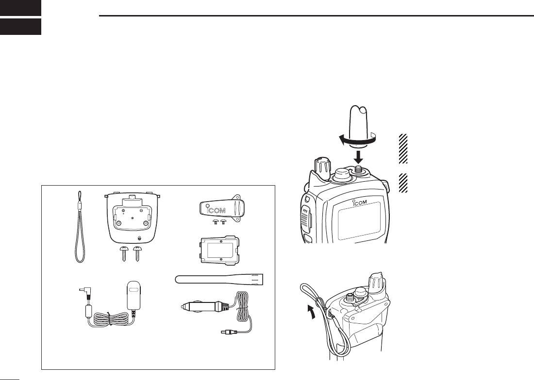
■ Supplied accessories
The following accessories are supplied: Qty.
q Handstrap ....................................................................... 1
w Battery charger (with two screws) ................................. 1
e Belt clip (with two screws)............................................... 1
r Li-Ion battery pack ......................................................... 1
t AC adapter .................................................................... 1
y Flexible antenna ............................................................ 1
u Cigarette lighter cable .................................................... 1
■ Attachments
Flexible antenna D
Connect the supplied flexible
antenna to the antenna connector.
CAUTION: Transmitting without
an antenna may damage the
transceiver.
NEVER HOLD by the antenna
when carrying the transceiver.
Handstrap D
Pass the handstrap through the
loop on the top corner of the
transceiver as illustrated at left.
Facilitates carrying.
qw e
r
ty
u
(Not supplied or different type
may be supplied depending
on the version)
(May not be supplied,
depending on the version)
3
2
SUPPLIED ACCESSORIES AND ATTACHMENTS
1
2
3
4
5
6
7
8
9
10
11
12
13
14
15
16
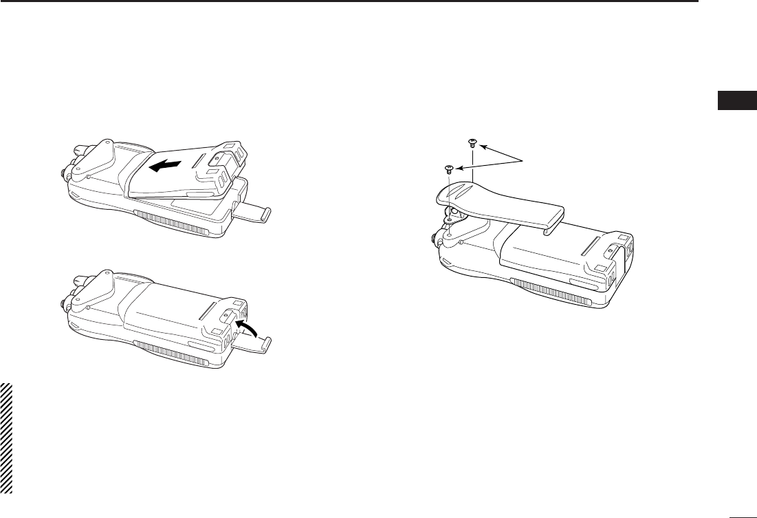
D Battery pack
q Attach the battery pack into the transceiver as below.
w Lock the battery pack with the latch.
CAUTION:
NEVER attach or detach the battery pack when wet.
Be careful when releasing the latch. Because the latch is
tightly locked, don’t use a finger nail to open it— you may
injure yourself. Instead, use something relatively flat, like
the edge of a coin or the tip of a screwdriver, to carefully
release the latch.
D Belt clip
Attach the belt clip to the transceiver as illustrated below.
Supplied screws
4
PANEL DESCRIPTION
3
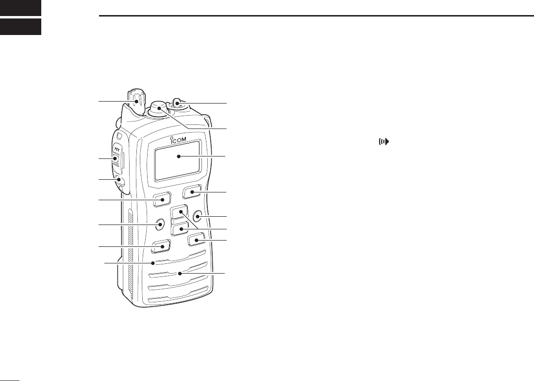
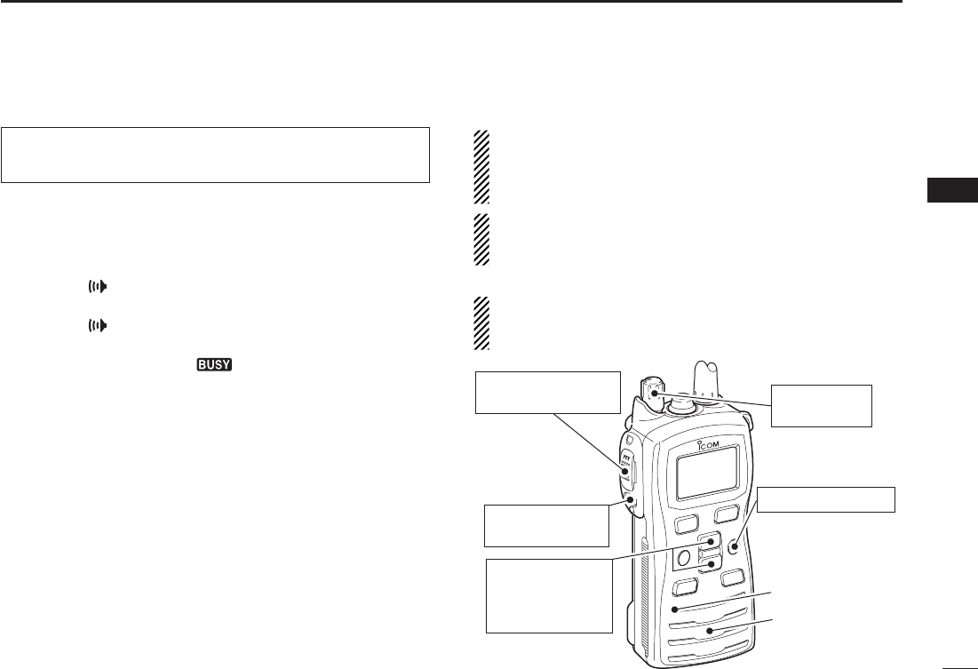
■ Front, top and side panels
q
w
e
y
t
r
Microphone
!2
!1
!0
o
u
i
Speaker
Function
display
(p. 6)
q VOLUME CONTROL [VOL]
Turns power ON and adjusts the audio level.
w PTT SWITCH [PTT]
Hold down to transmit; release to receive.
e MONITOR KEY []
while held down. (p. 10)
Y]/
Z]. (p. 11)
the SET mode. (p. 17)
r CHANNEL16KEY[16/C]
(p. 7)
(p. 7)
Enters call channel write mode when the call channel is
selected and this key is held down for 3 seconds. (p. 10)
t FUNCTION KEY [F]
(p. 7)
1 second. (p. 7)
y SCANKEY[SCAN•DUAL]
(pp. 14, 15)
(p. 16)

5
3
PANEL DESCRIPTION
1
2
3
4
5
6
7
8
9
10
11
12
13
14
15
16
u CHANNEL/WEATHER CHANNEL KEY
[CH/WX•U/I/C](IC-M73),[CH](IC-73EURO)
channel* when pushed. (p. 8)
group when held down for 1 second. (p. 8)
- The function display shows which channel group is
active.
channel when the priority channel or the call channel is
selected.
*Available with the U.S.A. and EXP versions only.
NOTE: [CH/WX•U/I/C] and [CH] write as [CH/WX•U/I/
C] in this instruction manual.
i CHANNEL UP/DOWN KEYS [Y]/[Z]
(pp. 7–9)
(p. 17)
].
(p. 17)
direction during scan. (p. 15)
o TRANSMITPOWER/LOCKKEY[H/L•LOCK]
(p. 9)
second. (p. 10)
!0 FAVORITE(TAG)KEY[FAV•★]
channels, while ignoring untagged channels, in a
channel group. (p. 8)
the displayed channel. (p. 8)
set all Favorite (TAG) channels in the selected channel
group. (p. 8)
!1 SPEAKER-MICROPHONE CONNECTOR [SP MIC]
Connects the optional external speaker-microphone or
headset.
NOTE: Attach the [SP MIC] cap when the optional
speaker-microphone or headset is not used.
!2 ANTENNA CONNECTOR
Connects the supplied antenna.
6
3PANEL DESCRIPTION
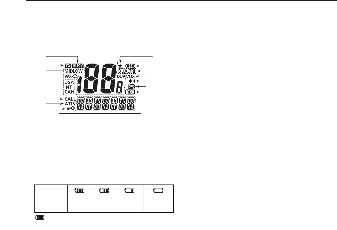
■ Function display
q
w
r
u
e
t
i
y
o
!1 !2
!4
!3
!5
!6
!7
!0
q CHANNEL NUMBER READOUT
w FAVORITE CHANNEL INDICATOR (p. 15)
Appears when favorite channel is selected.
e BATTERY INDICATOR
Indicates remaining battery power.
Indication
Full Middle Charging
required No battery
Battery level
blinks when the battery is overcharged (or over voltage).
r DUALWATCH/TRI-WATCH INDICATORS (p. 16)
“DUAL” blinks during dualwatch; “TRI” blinks during tri-
watch.
t VOX INDICATOR (p. 12)
Appears when the VOX function using is available.
Ask your dealer for details.
y MONITOR INDICATOR (p. 10)
Appears when the monitor function is activated.
u AUTOMATIC RECORDING INDICATOR (pp. 11, 22)
Appears when the automatic recording is activated.
i RECORDING INDICATOR
Appears while the receiving audio is recording.
o CHANNEL NAMING
comment. (p. 13)
17–22)
!0 LOCK INDICATOR (p. 10)
Appears when the lock function is activated.
!1 ATIS INDICATOR (p. 10)
Appears when the channel group, which ATIS function is
activated, is selected.

7
3
PANEL DESCRIPTION
1
2
3
4
5
6
7
8
9
10
11
12
13
14
15
16
!2 CALL CHANNEL INDICATOR (p. 7)
Appears when the call channel is selected.
!3 CHANNEL GROUP INDICATOR (p. 8)
“USA” appears when U.S.A.; “INT” appears when
International; “CAN*” appears when Canadian channel
group is selected.
*Available with the U.S.A. and EXP versions only
!4 WEATHER CHANNEL/WEATHER ALERT INDICATORS
(p. 8)
” appears when the weather channel group is
selected.
” appears when the weather alert function is
activated.
!5 TRANSMIT POWER INDICATORS (p. 9)
!6 TRANSMIT INDICATOR (p. 9)
Appears during transmit.
!7 BUSY INDICATOR (pp. 9, 10)
Appears when a signal is received or squelch is open.
8
BASIC OPERATION
4
■ Channel selection
IMPORTANT!: Prior to using the transceiver for the first
time, fully charge the battery pack. This will help maxi-
mize the capability and life of the battery. To avoid dam-
age to the transceiver, turn the radio OFF while charging.
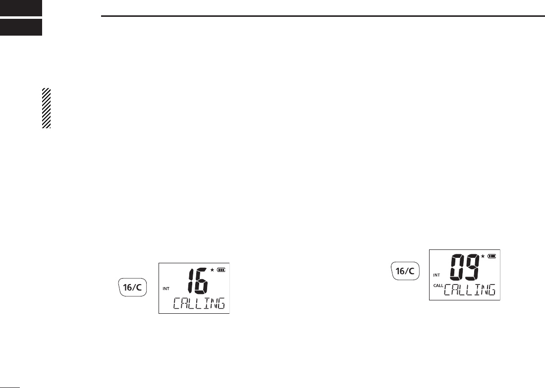
DChannel16
Channel 16 (Distress channel) is used for establishing initial
contact with another station and for emergency communica-
tions. Channel 16 is automatically monitored during both du-
alwatch and tri-watch. While standing by, you must monitor
Channel 16.
q Push [16•9] to select Channel 16.
w Push [CH/WX•U/I/C] to return to the condition before
selecting Channel 16, or push [Y]/[Z] to select the
operating channel.
Push
D Channel 9 (Call channel)
Channel 9 is the leisure-use call channel. Each regular
channel group has separate call channels. In addition, the
call channel is monitored during tri-watch. The call channels
can be re-programmed (p. 10) and may be used to store your
most often used channels in each channel group for quick
recall.
q Hold down [16•9] for 1 second to select the call channel.
programming” on p. 10 for details.
w Push [CH/WX•U/I/C] to return to the condition before
selecting Channel 9 (call channel), or push [Y]/[Z] to
select the operating channel.
Hold down
for 1 sec.
9
4
BASIC OPERATION
1
2
3
4
5
6
7
8
9
10
11
12
13
14
15
16
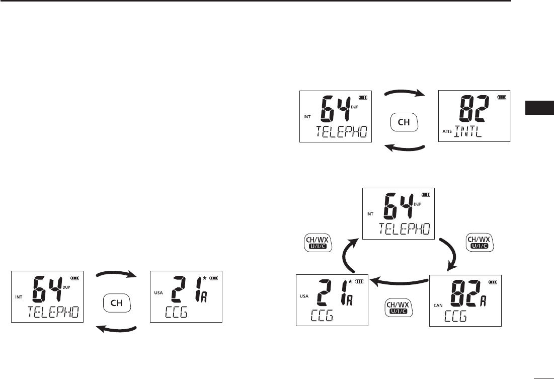
D U.S.A., International, Canadian and ATIS
channels
The IC-M73/IC-M73EURO have U.S.A.*1, International,
Canadian*2 and ATIS*3 channels. You must select the proper
channels for the operating area.
*1U.S.A., EXP, China and U.K. versions only
*2U.S.A and EXP versions only.
*3German and Holland versions only.
q Push [CH/WX•U/I/C] to select the regular channel.
[CH/WX•U/I/C] again.
w Push [Y]/[Z] to select a channel.
e To change the channel group, hold down [CH/WX•U/I/C]
for 1 second.
For U.K. version
U.S.A. channelsInternational channels
Hold down
for 1 sec.
Hold down
for 1 sec.
Hold down
for 1 sec.
Hold down
for 1 sec.
Hold down
for 1 sec.
For German and Holland versions
For U.S.A. and China versions
International channels
International channels
U.S.A. channels
ATIS channels
Canadian channels

10
4BASIC OPERATION
D Weather channels
The IC-M73 has 10 weather channels. They are used for
monitoring NOAA (National Oceanographic and Atmospheric Ad-
ministration) broadcasts (reception of weather channels possible
in U.S.A. only).
q Push [CH/WX•U/I/C] to select the weather channel group.
w Push [Y]/[Z] to select a weather channel.
e Push [CH/WX•U/I/C] to return to the condition before
selecting the weather channel group.
✔ CONVENIENT!
The IC-M73 can detect a weather alert tone on the selected
weather channel while in another channel (when the power
save function is turned ON) or during scanning. See the “SET
mode items” on p. 18 for details.
11
4
BASIC OPERATION
1
2
3
4
5
6
7
8
9
10
11
12
13
14
15
16
■ Receiving and transmitting
CAUTION: Transmitting without an antenna may
damage the transceiver.
q Rotate [VOL] clockwise to turn power ON.
[16/•] to skip the opening comment indication.
w Set the volume and squelch level.
➥ Push [], and push [Z] to open the squelch.
➥ Rotate [VOL] to set the volume level.
➥ Push [], and push [Y]/[Z] to set the squelch level.
e Push [Y]/[Z] to select the desired channel.
- When receiving a signal, “ ” indicator appears while audio
is emitted from the speaker.
- Further adjustment of [VOL] may be necessary at this point.
r Push [H/L•LOCK] to select the output power, if necessary.
- “LOW” appears when low power is selected; “MID” appears
when middle power is selected; no indication when high power
is selected.
- Choose low or mid. power to conserve battery power, choose
high power for longer distance communications.
- Some channels are for low power only.
t Hold down [PTT] to transmit, and speak into the
microphone.
- The transmit indicator appears while transmitting.
- Channel 70 cannot be used for transmission.
y Release [PTT] to receive.
IMPORTANT: To maximize the readability of your trans-
mitted signal, pause a second after pushing [PTT], hold
the microphone 5 to 10 cm (2 to 4 inches) from your mouth,
and speak into the microphone using a normal voice level.
NOTE: The transceiver has a power save function to con-
serve the battery power. The power save function acti-
vates automatically when no signal is received for 5 sec-
onds.
To prevent accidental prolonged transmission, etc., the
IC-M73 has a time-out timer function. This timer cuts a
transmission OFF after 5 min. of continuous transmission.
q Power ON
w Set volume
w Set the squelch
level
w Set the squelch
level
e Select the
channel
r Set output power
t Push to transmit
y Release to receive
Microphone
Speaker
12
4BASIC OPERATION
12
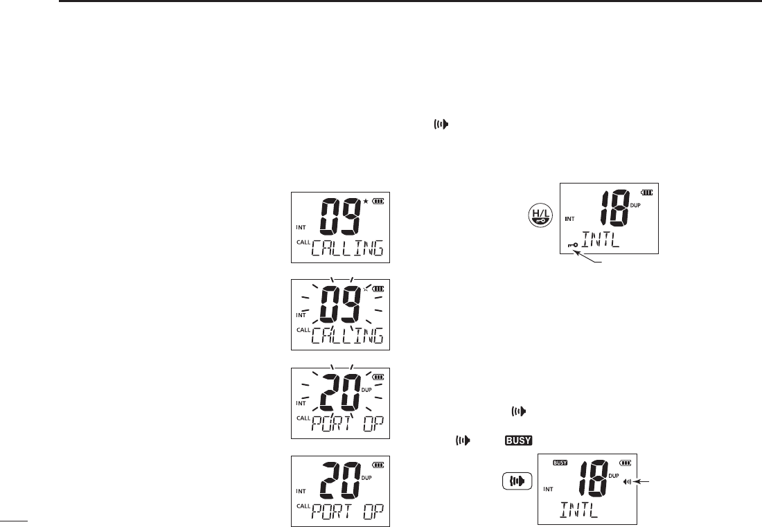
■ Call channel programming
The call channel key is used to select Channel 9 by default,
however, you can program your most often-used channel in
each channel group for quick recall.
q Hold down [CH/WX•U/I/C] for 1 second several times to
select the desired channel group (USA, INT, CAN) to be
programmed.
w Hold down [16•9] for 1 second to
select the call channel.
e Hold down [16•9] a gain fo r 3
seconds (until a long beep changes to
2 short beeps) to enter call channel
programming condition.
blinks.
r Push [Y]/[Z] to select the desired
channel.
t Push [16•9] to program the displayed
channel as the call channel.
■ Lock function
This function electronically locks all keys (except for [PTT],
[] and [H/L•LOCK]) to prevent accidental channel changes
and function access.
➥ Push [H/L•LOCK] for 1 second to turn the lock function
ON or OFF.
Hold down
for 1 sec.
Appears while the loc
k
function is in use.
■ Monitor function
The monitor function releases the noise squelch mute to
check the volume level. See p. 19 for details of the monitor
switch action.
➥ Hold down [] for 1 second to activate the monitor func-
tion.
” and “ ” appear and audio is emitted.
Appears while the
monitor function is
in use.
Hold down
for 1 sec.

13
4
BASIC OPERATION
1
2
3
4
5
6
7
8
9
10
11
12
13
14
15
16
■ Adjusting the squelch level
To adjust the IC-M73/IC-M73EURO’s squelch level, use the
[Y]/[Z] keys as desired below. In order to receive signals
properly, as well as for the scan to function effectively, the
squelch must be adjusted to the proper level.
q Push [], then adjust the squelch level with [Y]/[Z].
- “SQL” and the squelch level are displayed.
- There are 11 squelch levels to choose from: OP is completely
open; 10 is tight squelch; 1 is loose squelch level.
- When no key is pushed for 5 seconds, the transceiver returns to
normal condition.
w Push [] again to return to normal operating mode.
Push Shows the squelch
level.
Appears during squelch
level adjustment
■ AquaQuake water draining function
The IC-M73/IC-M73EURO uses a new technology to clear
water away from the speaker grill: AquaQuake. AquaQuake
helps drain water away from the speaker housing (water that
might otherwise muffle the sound coming from the speaker). The
IC-M73/IC-M73EURO emits a vibrating noise when this
function is being used.
➥ Hold down [F].
-
less of [VOL] control setting.
The transceiver never accepts a key operation while the Aqua-
Quake function is activated. And this function won’t be activated
when an optional speaker-microphone or headset is connected.
14
SCAN OPERATION
5
■ Scan types
Scanning is an efficient way to quickly locate signals over a
wide frequency range. The transceiver has a priority scan
setting and normal scan setting.
In addition, the “Weather alert” and “Auto scan” functions are
also available for scanning. These functions can be activated
simultaneously, depending on the settings on the SET mode.
(pp. 18, 19)
Set the Favorite channels (scanned channel) before scanning.
Clear those Favorite channels which are not needed or in-
conveniently stop scanning, such as digital communications.
Choose priority or normal scan on the SET mode. (p. 18)
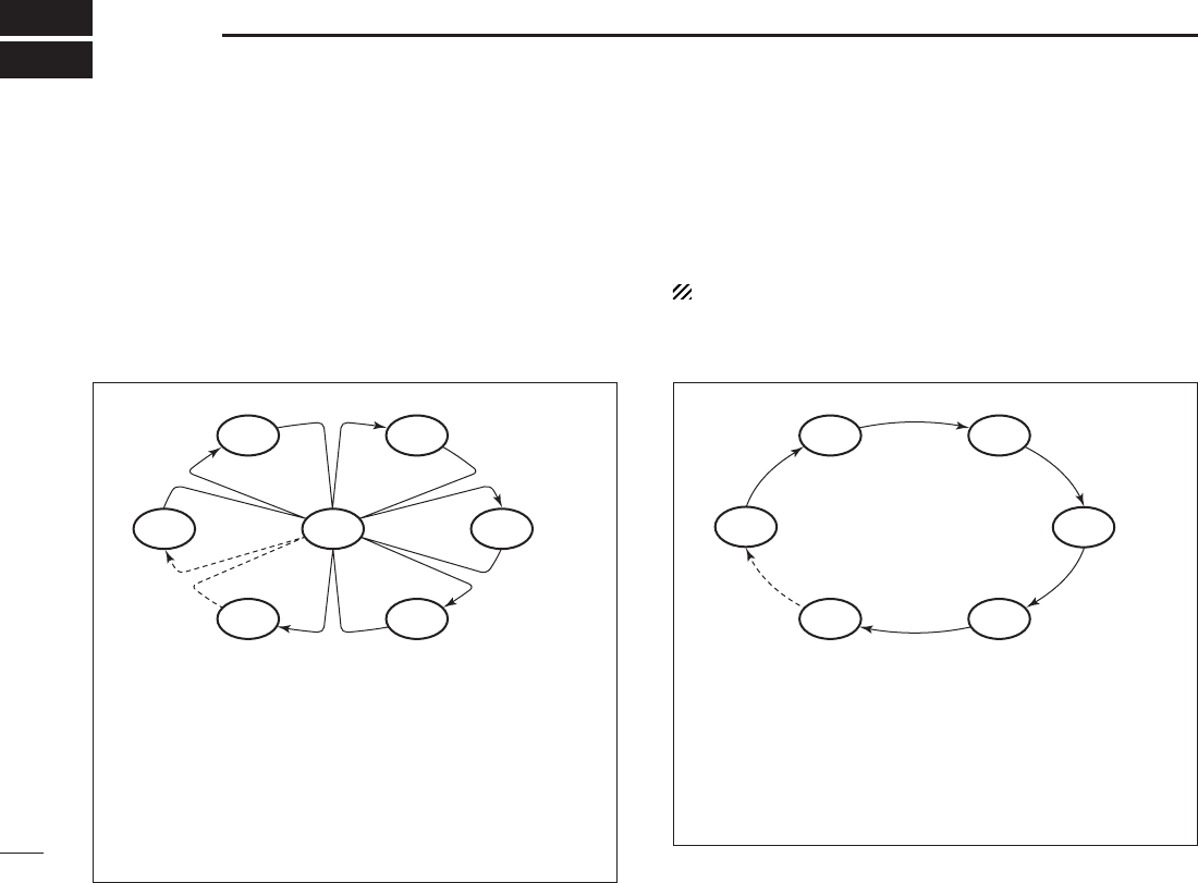
PRIORITY SCAN
WX*
CH 01
CH 16
CH 02
CH 05 CH 04
CH 03
* Previously selected weather channel
when weather alert function is ON
Priority scan searches through all
Favorite
channels in
sequence while monitoring Channel 16. When a signal is
detected on Channel 16, scan pauses until the signal disap-
pears; when a signal is detected on a channel other than
Channel 16, scan becomes dualwatch until the signal disap-
pears.
NORMAL SCAN
CH 01 CH 02
WX*
CH 05 CH 04
CH 03
* Previously selected weather channel
when weather alert function is ON.
Normal scan, like priority scan, searches through all Fa-
vorite channels in sequence. However, unlike priority scan,
Channel 16 is not checked unless Channel 16 is set as a
Favorite channel.
15
5
SCAN OPERATION
1
2
3
4
5
6
7
8
9
10
11
12
13
14
15
16
■ Setting Favorite channels
For more efficient scanning, add desired channels as Favor-
ite channels or clear the Favorite for unwanted channels.
Untagged will be skipped during scanning. Favorite channels
can be assigned to each channel group (USA, INT, CAN) in-
dependently.
q Select the desired channel to set as a Favorite channel.
w Hold down [FAV•★] for 1 second to set the displayed
channel as a Favorite channel.
★” appears in the function display.
e To cancel the Favorite channel setting, hold down
[FAV•★] for 1 second.
★” disappears.
✔ Clearing All Favorite Channels in the Selected Channel
Group
While holding down [FAV•★], turn power ON to clear all Fa-
vorite channels setting in the channel group.
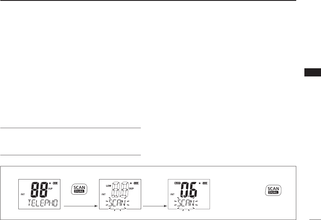
■ Starting a scan
Set the weather alert function, priority scan function, scan
resume timer and auto scan function in advance, using the
SET mode. (pp. 18, 19)
q Make sure the desired channel group (e.g., USA, CAN, INT)
is selected. Move between channel groups by repeatedly
pushing [CH/WX•U/I/C] for 1 second at a time.
weather channel with [CH/WX•U/I/C] and [Y]/[Z].
w Push [SCAN•DUAL] to start priority or normal scan.
When a signal is received, scan pauses until the signal disappears
or resumes after pausing 5 seconds according to scan resume
timer setting. (Channel 16 is still monitored during priority scan.)
[Y]/[Z] to check the scanning Favorite channels, change
the scanning direction or resume the scan manually.
e To stop the scan, push [SCAN•DUAL].
[PTT], [16•9] or [CH/WX•U/I/C] also stops the scan.
Scan starts
“SCAN” indication blinks
Push Push
to stop the scan
When receiving a
signal, “SCAN” indica-
tion blinks and audio
is emitted.
[Example]: Starting a normal scan.
16
DUALWATCH/TRI-WATCH
6
■ Description
Dualwatch monitors Channel 16 while you are receiving
another channel; tri-watch monitors Channel 16 and the call
channel while receiving another channel.
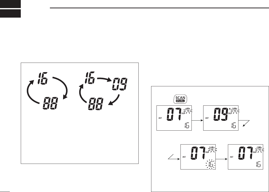
■ Operation
q Select the desired operating channel.
w Hold down [SCAN•DUAL] for 1 second to start dualwatch
or tri-watch (depending on the SET mode setting; p. 19).
call channel.
e To cancel dualwatch/tri-watch, push [SCAN•DUAL] again.
DUALWATCH/TRI-WATCH SIMULATION
DualwatchTri-watch
Call channel
pauses on Channel 16 until the signal disappears.
watch, tri-watch becomes dualwatch until the signal dis-
appears.
watch, hold down [PTT].
[Example]: Operating tri-watch on INT channel 07.
Signal is received
on the call channel.
A signal receive on
Channel 16 always
takes priority.
Tr i-watch resumes
after the signal
disappears.
Tr i-watch starts.
Hold down for 1 sec.
17
7
FUNCTION MODE OPERATION
1
2
3
4
5
6
7
8
9
10
11
12
13
14
15
16
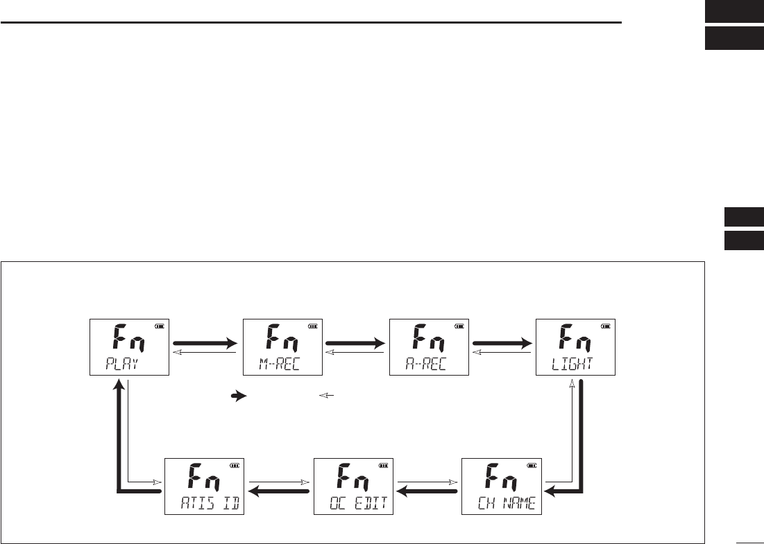
■ About the function mode
There are 7 transceiver functions in the function mode: Play
back function, Manual recording function, Automatic record-
ing function, backlight function, channel naming function,
opening comment entry function and ATIS code program-
ming function†.
†Depending on versions.
D Entering the function mode
q Turn power ON.
w Push [F] to enter the function mode.
e Push [Y]/[Z] to select the desired item.
r Push [H/L•KEY] to select or decide the desired condition
of the item.
[H/L•KEY].
t To exit the function mode, push [F].
D FUNCTION MODE ITEMS
Playback function*
Manual recording
function
Automatic recording
fucntion Backlight function
ATIS code programming
function†
Opening comment
entry function
Channel naming
function
: Push [Y] : Push [Z] *Starting item
†Availability may differ according to versions.
18
7FUNCTION MODE OPERATION
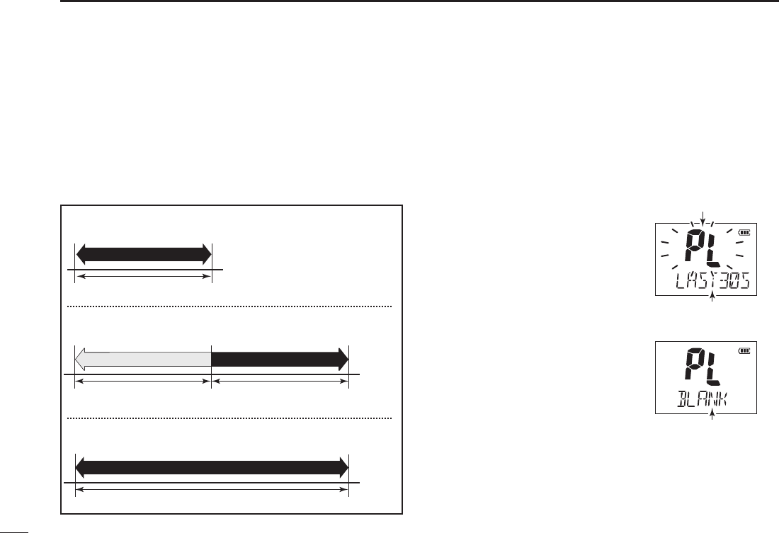
■ Play back function
This transceiver has the two voice recorders.
One is the manual recording function which can record for
30 seconds, the other is the automatic recording function
which can record the end of 60 seconds of the receiving sig-
nal.
There are three playing back mode as follow.
q Push [F] to enter the function mode.
w Push [H/L•KEY]to enter the play back selection mode,
and then push [Y]/[Z] to select the desired play back
mode from “M-PLAY,” “LAST30S,” or “LAST60S.”
If there is no recorded signal in the transceiver, “BLANK”
is appeared.
recorded signal.
recorded signal from
last 30 seconds.
recorded signal.
e Push [H/L•KEY] to play back the
recorded signal.
[H/
L•KEY] again.
Blinks while playbacking.
Playback mode appears.
“BLANK” is appeared
when the transceiver
has no recorded signal.
ding
ding
ding
Playing back 30 seconds (maximum).
Select “M-PLAY”
Select “LAST60S”
Select “LAST30S”
Not playing back.
Playing back for 60 seconds (maximum).
Playing back for
30 seconds (maximum).
19
7
FUNCTION MODE OPERATION
1
2
3
4
5
6
7
8
9
10
11
12
13
14
15
16
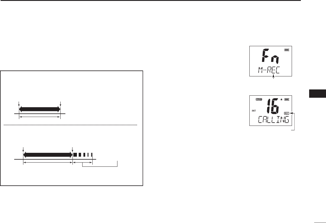
■ Manual recording function
You can record the received signal whenever you want by
using the manual recording function.
This function can record the receiving signal for 30 seconds.
q Push [F] to enter the function
mode, and then push [Y]/[Z]
to select the manual recording
function.
w Push [H/L•KEY]to star t to
record the receiving signal.
stop after 30 seconds.
e The recording will automatically
stop after 30 seconds.
[F] to stop the recording.
Manual recording
mode appears.
“REC” is appeared
while recording.
Example— Manual recording
[Less than 30 seconds]
[More than 30 seconds]
20 seconds
30 seconds
When receiving signal within 30
seconds, this function records
the all contents.
After passing 30 seconds from starting the manual
recording, the recording will be automatically stopped.
These contents
won’t be recorded.
Tu rn the manual
recording ON.
Tu rn the manual
recording ON.
Tu rn the manual
recording OFF.
Stops recording
automatically.
20
7FUNCTION MODE OPERATION
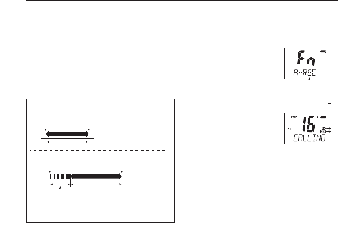
■ Automatic recording function
When this function turns ON, the transceiver automatically
records the receiving signal into the memory.
A maximum recording length of 60 seconds can be recorded
into the memory.
for details.
q Push [F] to enter the function
mode, and then push [Y]/[Z] to
select the automatic recording
function.
w Push [H/L•KEY]to turn the
function ON or OFF.
appeared.
automatically cancelled after
pushing [H/L•KEY].
e When the transceiver receives
a signal, it will automatically re-automatically re-
cord the receiving signal into the
memory.
stop when the receiving signal disappears.
Automatic recording
mode appears.
“REC” is appeared
while recording.
Automatic recording
icon is appeared.
• Example— Automatic recording
[Less than 60 seconds]
[More than 60 seconds]
40 seconds
60 seconds
When receiving signal within 60
seconds, this function records
the all contents.
After passing 60 seconds from
starting automatic recording, this
function records the 60 seconds
before stopping the record.
These contents
won’t be recorded.
Starts recording
Starts recording
Stops recording
Stops recording
21
7
FUNCTION MODE OPERATION
1
2
3
4
5
6
7
8
9
10
11
12
13
14
15
16
■ Backlighting function
This function is convenient for nighttime operation. The back-
lighting can be turned OFF in the SET mode. (p. 19)
➥
Push any key other than [PTT] to turn the backlighting ON.
inactivity.
q Push [F] to enter the function mode,
and then push [Y]/[Z] to select the
backlighting function.
w Push [H/L•KEY]to turn the function
ON or OFF.
cancelled after pushing [H/L•KEY].
e Push any key other than [PTT] to turn the backlighting
ON.
inactivity.
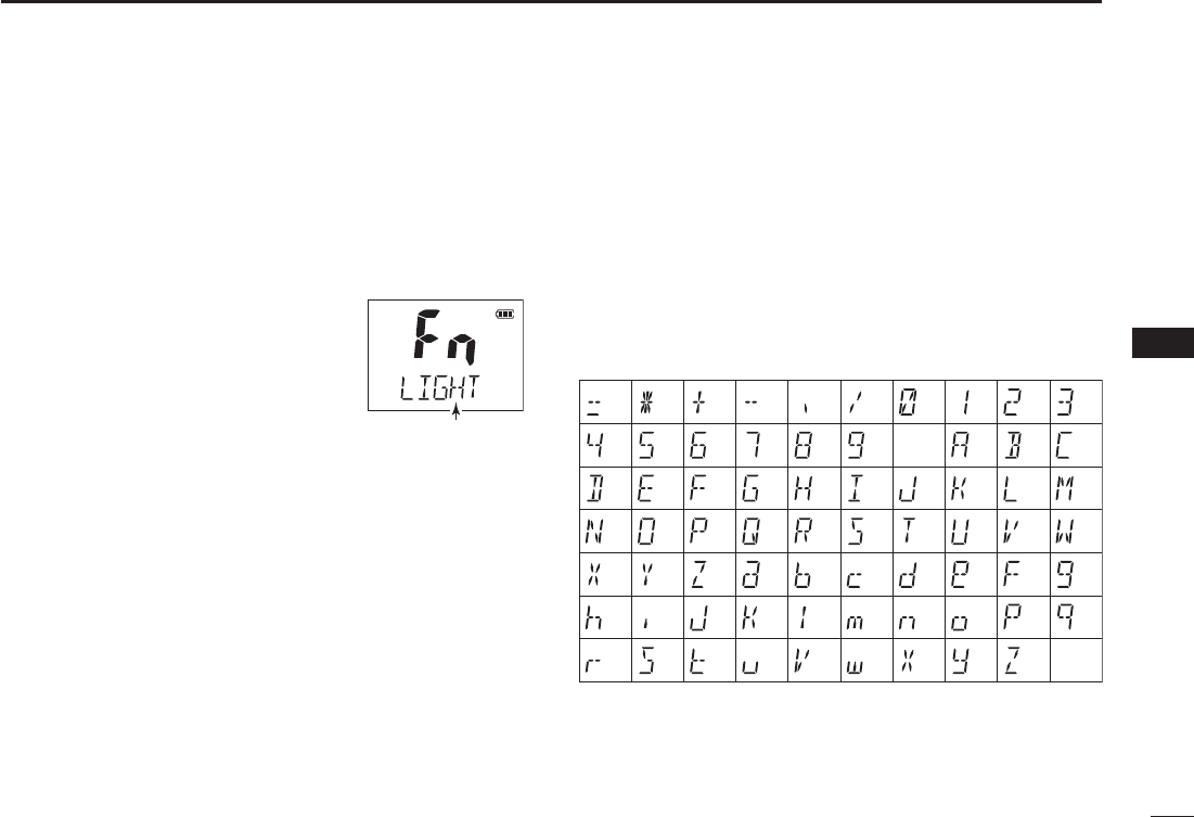
■ Channel naming function
The IC-M73/IC-M73EURO has a capability to assign up to
10-character channel names for each operating channel,
including each weather channel. This provides easy
recognition of channel usage, or station names, etc.
When shipped from the factory, the IC-M73/IC-M73EURO
is programmed with default names for each VHF marine
channel. These defaults can be changed, if desired.
D Available characters
(=)
(4)
(D)
(N)
(X)
(h)
(r)
(�)
(5)
(E)
(O)
(Y)
(i)
(s)
(+)
(6)
(F)
(P)
(Z)
(j)
(t)
(7)
(G)
(Q)
(a)
(k)
(u)
(,)
(8)
(H)
(R)
(b)
(l)
(v)
(/)
(9)
(I)
(S)
(c)
(m)
(w)
(0)
(Space)
(J)
(T)
(d)
(n)
(x)
(1)
(A)
(K)
(U)
(e)
(o)
(y)
(2)
(B)
(L)
(V)
(f)
(p)
(z)
(3)
(C)
(M)
(W)
(g)
(q)
(–)
Backlight mode
appears.
22
7FUNCTION MODE OPERATION
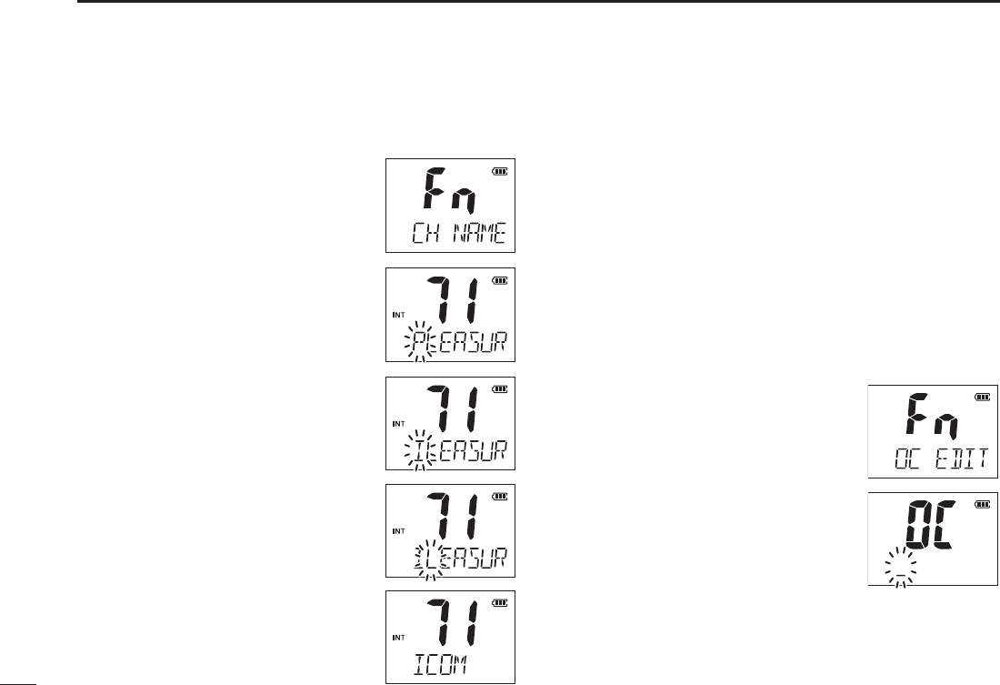
D Channel name programming
q Push [Y]/[Z] to select a channel to
program.
[CH/WX•U/I/C] for 1 second
to select a channel group, if necessary.
w Push [F] to enter the function mode,
and then push [Y]/[Z] to select the
channel naming function.
e Push [H/L•KEY]to edit the channel
name.
programmed name blinks.
r Push [Y]/[Z] to select a character.
t Push [CH/WX•U/I/C] to move to the
right; then push [Y]/[Z] to select a
character.
[SCAN•DUAL], moves to left
y Continue until the desired charac-
ters have been selected, then push
[H/L•KEY] to return to normal opera-
tion.
■ Opening comment entry
function
The IC-M73/IC-M73EURO has a capability to assign up to
10-character opening comments.
You may replace the factory-set opening comment with
a comment of your own. The opening comment appears
each time the IC-M73/IC-M73EURO is powered ON. The
comment may be up to 16 characters long.
You can use same characters as “Channel naming function.”
(p. 22)
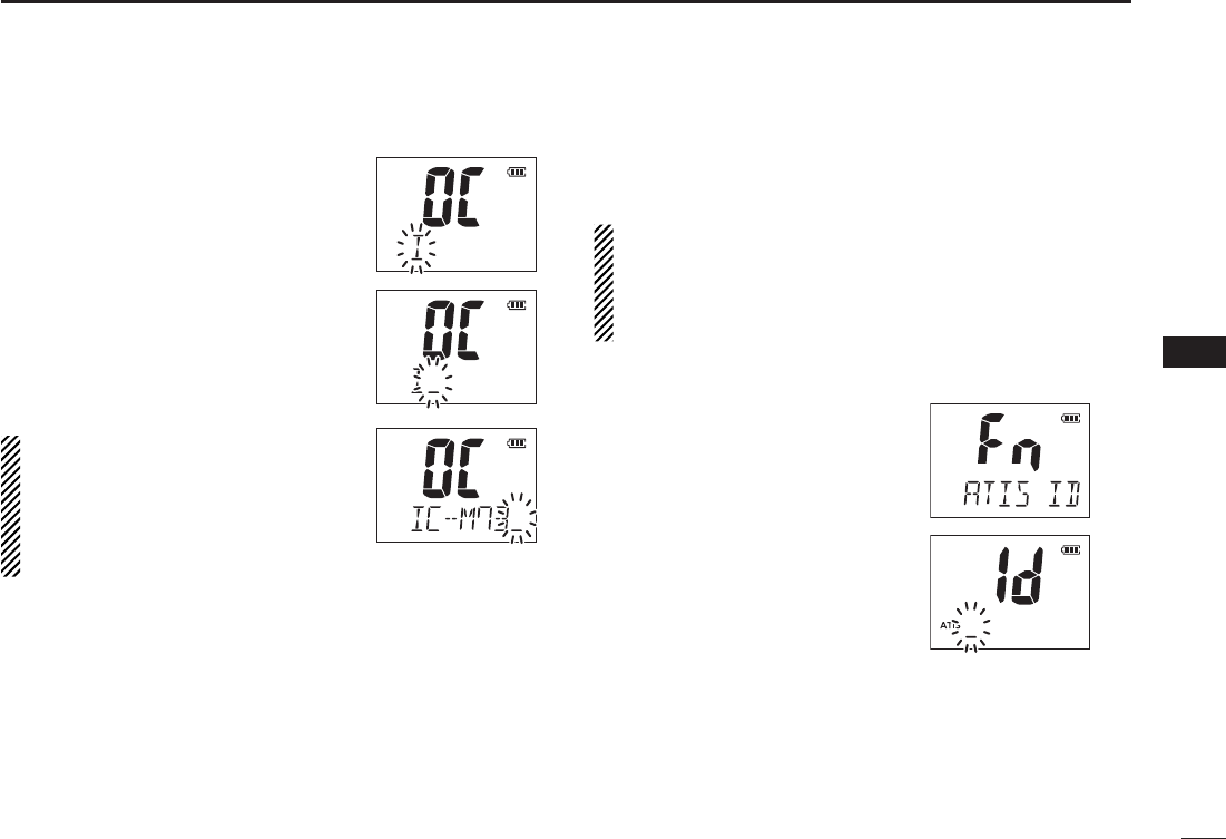
D Opening comment programming
q Push [F] to enter the function mode,
and then push [Y]/[Z] to select the
channel naming function.
w Push [H/L•KEY]to edit the opening
comment.
programmed comment blinks.
23
7
FUNCTION MODE OPERATION
1
2
3
4
5
6
7
8
9
10
11
12
13
14
15
16
e Push [Y]/[Z] to select a character.
r Push [CH/WX•U/I/C] to move to the
right; then push [Y]/[Z] to select a
character.
[SCAN•DUAL], moves to left
t Continue until the desired charac-
ters have been selected, then push
[H/L•KEY] to return to normal op-
eration.
The programmed opening comment
is briefly displayed or scrolled when
the transceiver is powered ON.
However, the opening comment in-
dication can be skipped by pushing
[16•9].
■ ATIS code programming
The 10-digit ATIS code can be programmed and confirmed
with the following operation.
The ATIS code programming is not necessary and confi
rmation can only be performed when the ATIS code has
been programmed by your dealer. The code programming
can be performed 1 time only, when the code has not
been programmed by your dealer.
D Opening comment programming
q Push [F] to enter the function
mode, and then push [Y]/[Z] to
select the ATIS code program-
ming function.
w Push [H/L•KEY]to edit the ATIS
code.
character of the code blinks.
24
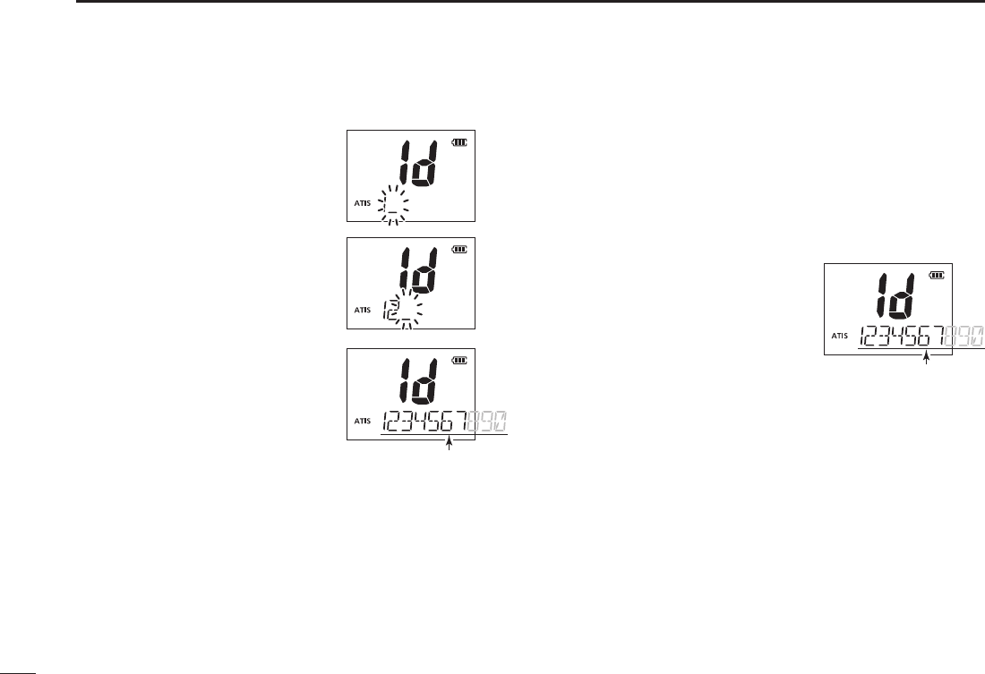
7FUNCTION MODE OPERATION
e Push [Y]/[Z] to select a char-
acter.
r Push [CH/WX•U/I/C] to move
to the right; then push [Y]/[Z]
to select a character.
[SCAN•DUAL], moves to
left
t After inputting the 10-digit ATIS
code, push [H/L•KEY] to write
the code into the memory, then
return to normal operation.
D ATIS code confirmation
(When the ATIS code has been programmed)
q Push [F] to enter the function mode, and then push [Y]/
[Z] to select the ATIS code programming function.
w Push [H/L•KEY]to confirm the ATIS code.
scrolls at the channel comment
indicator.
e Push [H/L•KEY]to return to
normal operation.
Scrolls
Scrolls
25
8
SET MODE
1
2
3
4
5
6
7
8
9
10
11
12
13
14
15
16
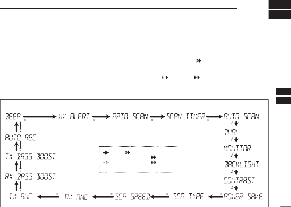
■ SET mode programming
SET mode is used to change the condition of 17 transceiver
functions: beep tone function, weather alert function, scan
type, scan resume timer, auto scan function, dual/tri-watch
function, monitor key action, backlighting function, LCD con-
trast selection, auto power save function, Scroll type selec-
tion, Scroll speed selection, RX noise cancel function, TX
noise function, RX bass boost function, TX bass boost func-
tion and automatic recording threshold level selection.
D SET mode operation
q Turn power OFF.
w While holding down [], turn power ON to enter the
SET mode.
e Push [], or push [ ] and [Y]/[Z] to select the de-
sired item.
r Push [Y]/[Z] to select the desired condition of the item.
t To exit the SET mode, push [16•9].
D SET MODE ITEMS
Beep tone* Weather alertPriority scan Scan resume timer
Auto scan start function
Dual/Tri-watch
Monitor key
action
Display
backlight
LCD
contrast
Automtic recording threshold level
TX bass boost
RX bass boost
Power save function
Scroll typeScroll speedRX noise cancel
TX noise cancel
: Push [ ], or
while holding down [ ], push [Y]
: While holding down [ ], push [Z]
*Starting item
26
8SET MODE
■ SET mode items
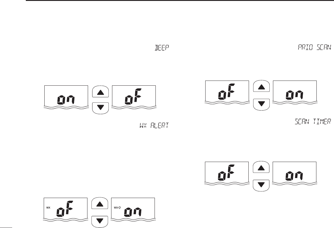
D Beep tone function “ ”
Selects the key touch beep sound ON or AJ, or turns sound
OFF.
Push
Beep tone ON (default) Beep tone OFF
D Weather alert function “”
A NOAA broadcast station transmits a weather alert tone
before any important weather announcements. When the
weather alert function is turned ON, any detected weather
alert will make the IC-M73 activate a blinking “WXALT” alert
indicator on the function display and repeatedly sound a
beep tone. The blinking and beeping stops when the radio
is picked up and operated. The previously selected weather
channel is checked any time during standby, or while scan-
ning, when the power save function is activated.
Push
Weather alert function
OFF (default)
Weather alert function
ON
D Priority scan function “ ”
The transceiver has 2 scan types— normal (OFF) and
priority (ON) scans. Normal scan searches all TAG channels
in the selected channel group. Priority scan searches all TAG
channels in sequence while monitoring Channel 16.
Push
Normal scan (default) Priority scan
D Scan resume timer “ ”
The scan resume timer can be set as a pause (OFF) or
timer scan (ON). When OFF is selected, the scan pauses
until a received signal disappears. When ON is selected, the
scan pauses for 5 seconds after receiving a signal and then
resumes even if the signal has been received.
Push
Scan resume timer
OFF (default)
Scan resume timer
ON
27
8
SET MODE
1
2
3
4
5
6
7
8
9
10
11
12
13
14
15
16
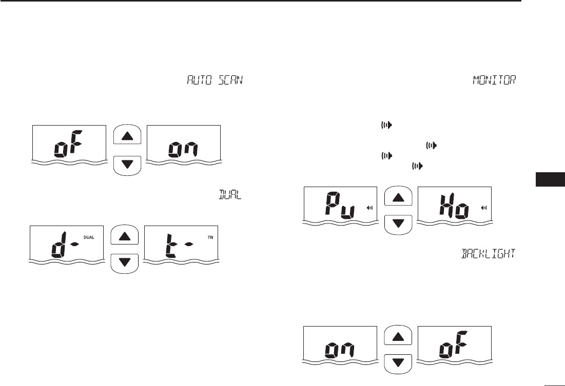
D Auto scan function “”
The auto scan function starts the desired scan automatically
when no signal is received, and no operation is performed
for 30 seconds
Push
Auto scan OFF (default) Auto scan ON
D Dual/Tri-watch function “”
This item selects dual or tri-watch as desired. See p. 16 for
details.
Push
Dualwatch (default) Tr i-watch
D Monitor key action “”
The monitor key action cuts off the squelch function
temporarily. This key action contains PUSH (Pu) or HOLD
(Ho) settings as shown below.
[] for 1 second, the squelch opens
and emits audio. The squelch is held open while
continuously holding down []. (default)
[ ] for 1 second, the squelch opens
and emits audio even [ ] is released. To close the
squelch, push any key.
Push
Push setting (default) Hold setting
D Backlight function “”
This function is convenient for nighttime operation. The
backlight can be selected from ON and OFF.
[PTT] is pushed.
inactivity.
Push
Backlight ON
(default)
Backlight OFF
28
8SET MODE
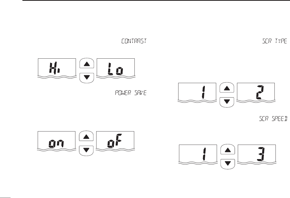
D LCD contrast selection “ ”
The contrast of the LCD can be selected from Hi (default)
and Lo.
Push
High contrast (default) Low contrast
D Auto power save function “ ”
The auto power save function reduces current drain by
deactivating the receiver circuit for preset intervals.
function will activate when no signal is received, and no
operation is performed for 5 seconds
Push
Power save ON
(default)
Power save OFF
D Channel name scroll type “ ”
Selects the channel name/comment scroll type from 1 and 2.
scrolls. When the channel name/comment is 7 character or less,
it does not scroll (default).
of characters after no name/comment (blank) is indicated for 1
second.
Push
Scroll type 1 (default) Scroll type 2
D Scrolling speed “”
Selects the channel name/comment scroll speed.
Push
Scroll speed 1 (default) Scroll speed 3
29
8
SET MODE
1
2
3
4
5
6
7
8
9
10
11
12
13
14
15
16
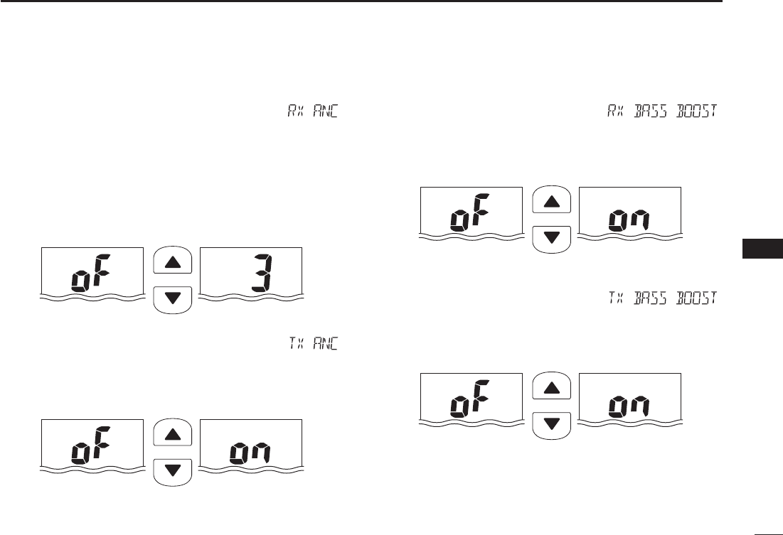
D RX Noise Cancel function “”
Set the Noise Cancel function for receive.
OFF : Turns OFF the function.
1 :
The Noise Cancel function reduces random noise compo-
nents in the received signal to approximately one half.
2 :
The Noise Cancel function reduces random noise compo-
nents in the received signal to approximately one third.
3 :
The Noise Cancel function reduces random noise compo-
nents in the received signal to approximately one tenth.
Push
RX noise cancel
OFF (default)
RX noise cancel 3
D TX Noise Cancel function “”
Set the Noise Cancel function for transmit.
OFF : Turns OFF the function.
ON : The Noise Cancel function reduces random noise com-
ponents in the transmitted signal to one third.
Push
TX noise cancel
OFF (default)
TX noise cancel ON
D RX bass boost function “ ”
Set the bass boost function for receive.
OFF : Turns OFF the function.
ON : The RX bass boost function boosts the level of the re-
ceive audio tone.
Push
RX bass boost
OFF (default)
RX bass boost ON
D TX bass boost function “ ”
Set the bass boost function for transmit.
OFF : Turns OFF the function.
ON : The TX bass boost function boosts the level of the
transmit audio tone.
Push
TX bass boost
OFF (default)
TX bass boost ON
30
8SET MODE
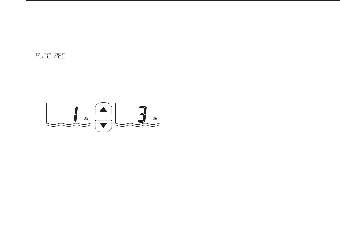
D Automatic recording threshold level
“”
Set the automatic recording threshold level.
1 :
Set the threshold level to shallow. The weak signal will
automatically record into the memory.
2 :
Set the threshold level to middle.
3 :
Set the threshold level to deep. The weak signal will not
automatically record into the memory.
Push
Automatic recording
threshold level 1 (default)
Automatic recording
threshold level 3

31
9
Battery charging
1
2
3
4
5
6
7
8
9
10
11
12
13
14
15
16
■ Battery cautions
Misuse of Lithium-ion batteries may result in the
following hazards: smoke, fire, or battery rupture.
Misuse can also cause other battery damage or
degradation of battery performance.
R DANGER! Use and charge only specified Icom battery
pack with Icom transceiver. Only Icom battery pack is
tested and approved for use with Icom transceiver. Using
third-party or counterfeit battery packs may cause smoke,
fire, or cause the battery to burst.
D Battery caution
R DANGER! DO NOT hammer or otherwise impact the
battery. Do not use the battery if it has been severely
impacted or dropped, or if the battery has been subjected
to heavy pressure. Battery damage may not be visible on
the outside of the case. Even if the surface of the battery
does not show cracks or any other damage, the cells inside
the battery may rupture or catch fire.
R DANGER! NEVER use or leave battery pack in
areas with temperatures above +60˚C (+140˚F). High
temperature buildup in the battery, such as could occur
near fires or stoves, inside a sun-heated car, or by setting
the battery in direct sunlight may cause the battery to
rupture or catch fire. Excessive temperatures may also
degrade battery performance or shorten battery life.
R DANGER! DO NOT expose the battery to rain, snow,
seawater, or any other liquids. Do not charge or use a wet
battery. If the battery gets wet, be sure to wipe it dry before
using. The battery by itself is not waterproof.
R DANGER! NEVER incinerate a used battery pack since
internal battery gas may cause a rupture or explosion.
R DANGER! NEVER solder the battery terminals, or
NEVER modify the battery pack. This may cause heat
generation, and the battery may rupture, emit smoke or
catch fire.
R DANGER! Use the battery only with the transceiver for
which it is specified. Never use a battery with any other
equipment, or for any purpose that is not specified in this
instruction manual.
R DANGER! If fluid from inside the battery gets in your
eyes, blindness can result. Rinse your eyes with clean
water, without rubbing them, and see a doctor immediately.
WARNING! Immediately stop using the battery if it emits
an abnormal odor, heats up, or is discolored or deformed. If
any of these conditions occur, contact your Icom dealer or
distributor.
WARNING! Immediately wash, using clean water, any part
of the body that comes into contact with fluid from inside
the battery.

32
9Battery charging
WARNING! NEVER put the battery in a microwave oven,
high-pressure container, or in an induction heating cooker.
This could cause overheating, a fire, or cause the battery
to rupture.
CAUTION! Always use the battery within the specified
temperature range for the transceiver (–20˚C to +60˚C;
–4˚F to +140˚F) and the battery itself (–20˚C to +60˚C;
–4˚F to +140˚F). Using the battery out of its specified
temperature range will reduce the battery’s performance
and battery life. Please note that the specified temperature
range of the battery may exceed that of the transceiver. In
such cases, the transceiver may not work properly because
it is out of its operating temperature range.
CAUTION! Shorter battery life could occur if the battery
is left fully charged, completely discharged, or in an
excessive temperature environment (above +45˚C; +113˚F)
for an extended period of time. If the battery must be left
unused for a long time, it must be detached from the radio
after discharging. You may use the battery until the remain-You may use the battery until the remain-
ing capacity is about half, then keep it safely in a cool dry
place with the temperature range as below;
–20˚C to +50˚C (–4˚F to +122˚F) (within a month)
–20˚C to +35˚C (–4˚F to +95˚F) (within three months)
–20˚C to +20˚C (–4˚F to +68˚F) (within a year)
D Charging caution
R DANGER! NEVER charge the battery pack in areas with
extremely high temperatures, such as near fires or stoves,
inside a sun-heated car, or in direct sunlight. In such
environments, the safety/protection circuit in the battery will
activate, causing the battery to stop charging.
WARNING! DO NOT charge or leave the battery in the
battery charger beyond the specified time for charging. If
the battery is not completely charged by the specified time,
stop charging and remove the battery from the battery
charger. Continuing to charge the battery beyond the
specified time limit may cause a fire, overheating, or the
battery may rupture.
WARNING! NEVER insert the battery and transceiver
(battery attached to the transceiver) into the charger if it
is wet or soiled. This could corrode the battery charger
terminals or damage the charger. The charger is not
waterproof.
CAUTION! DO NOT charge the battery outside of the
specified temperature range: ±0˚C to +45˚C (+32˚F to
+113˚F). Icom recommends charging the battery at +20˚C
(+68˚F). The battery may heat up or rupture if charged out
of the specified temperature range. Additionally, battery
performance or battery life may be reduced.
33
9
Battery charging
1
2
3
4
5
6
7
8
9
10
11
12
13
14
15
16
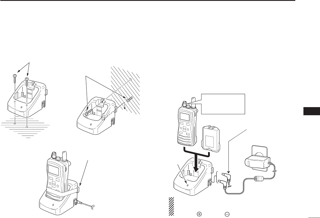
■ Supplied battery charger
DBC-210installation
q
w
e
Supplied screws
Supplied screws
• To a desktop
• For added stability
• To a wall
Eyelet:
Use a rubber band to
secure the transceiver,
if desired.
D Charging
q Connect the AC adapter as shown below.
w Insert the battery pack with/without the transceiver into
the charger.
e Charge the battery pack approx. 3 hours, depending on
the remaining power condition.
Transceiver
Battery pack
AC adapter
Charger
indicator
Tu rn the transceiver
power OFF during
charging.
OPC-515L* (for a
13.8 V power
source) or the
CP-25H (for a 12 V
cigarette lighter
socket) can be used
instead of the AC
adapter.
CAUTION: NEVER connect the OPC-515L to a power
source using reverse polarity. This will ruin the battery
charger.
White line: Black line :
*
34
9Battery charging
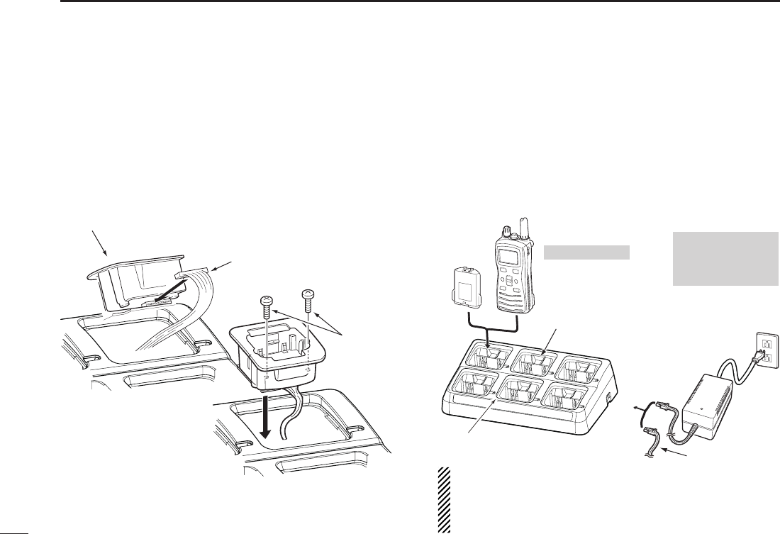
■ Optional battery chargers
DAD-129installation
q Connect 8-pin connector of the each charger slots to the
AD-129 desktop charger adapter’s plug.
w Install the adapter into the each charger slots in the
direction of the arrow, then use the supplied 2 screws to
secure the charger adapter to the charger.
DRapidchargingwiththeBC-197+BC-157S
or OPC-656
The optional BC-197 with the BC-157S will simultaneously
charge up to 6 Li-ion battery packs. The following items are
additionally required. (Charging time: approximately 2.5 hours)
(BC-157S) or the DC power cable (OPC-656)
Desktop charger adapter
8-pin connector
Supplied
screws
Battery
pack
The charger adapters
are installed in each slot.
The type of the charger
adapter depends on the
version of the BC-197.
Transceiver
Tu rn power OFF
NEVER transmit near
the BC-197 or the AC
adapter while
charging
(An AC adapter is
not supplied with
some versions.)
AC adapter
(Connect to a DC power supply: 12 to 16 V/at least 7 A)
Status indicator
(each indicator independently functions)
DC power cable (OPC-656)
OPC-656*
DC power cable
*
NEVER reverse the polarity when connecting the power cable to
a power source. This will ruin the battery charger.
Red line : + Black line : _
35
10
OPTIONAL SWIVEL BELT CLIP
1
2
3
4
5
6
7
8
9
10
11
12
13
14
15
16
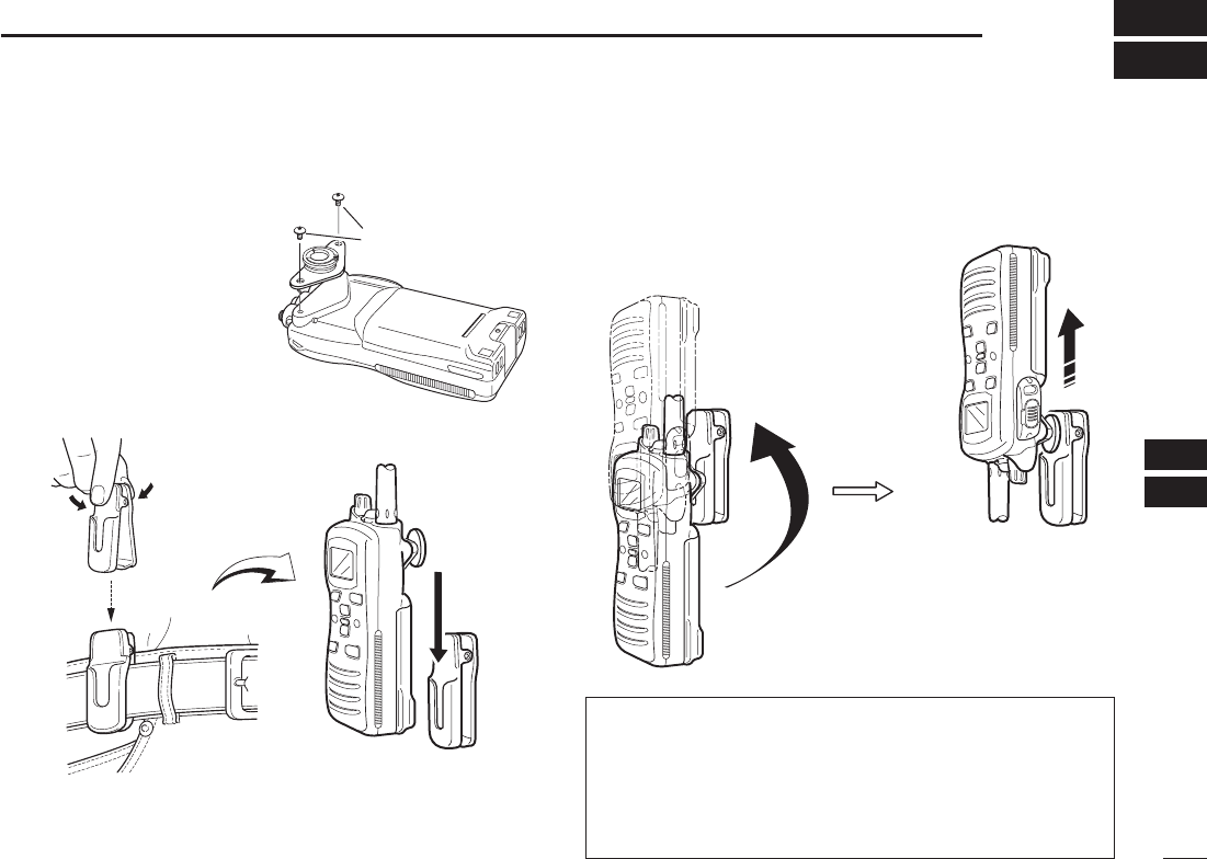
■ Attachment
q Screw the base clip to the
back of the transceiver
using the two screws (sup-
plied), as shown at right.
w Clip the belt clip over your belt and insert the transceiver.
e Once the transceiver is locked in place, it swivels.
■ Detachment
➥ Turn the transceiver upside down in the direction of the
arrow and pull out from the belt clip.
R CAUTION: HOLD THE TRANSCEIVER TIGHTLY
WHEN HANGING OR DETACHING THE TRANSCEIVER
FROM THE BELT CLIP.
Otherwise the transceiver may not be attached to the belt
clip or swivelled properly if the transceiver is accidentally
dropped and the base clip is scratched or damaged.
Supplied screws
36
OPTIONAL SPEAKER-MICROPHONE
11
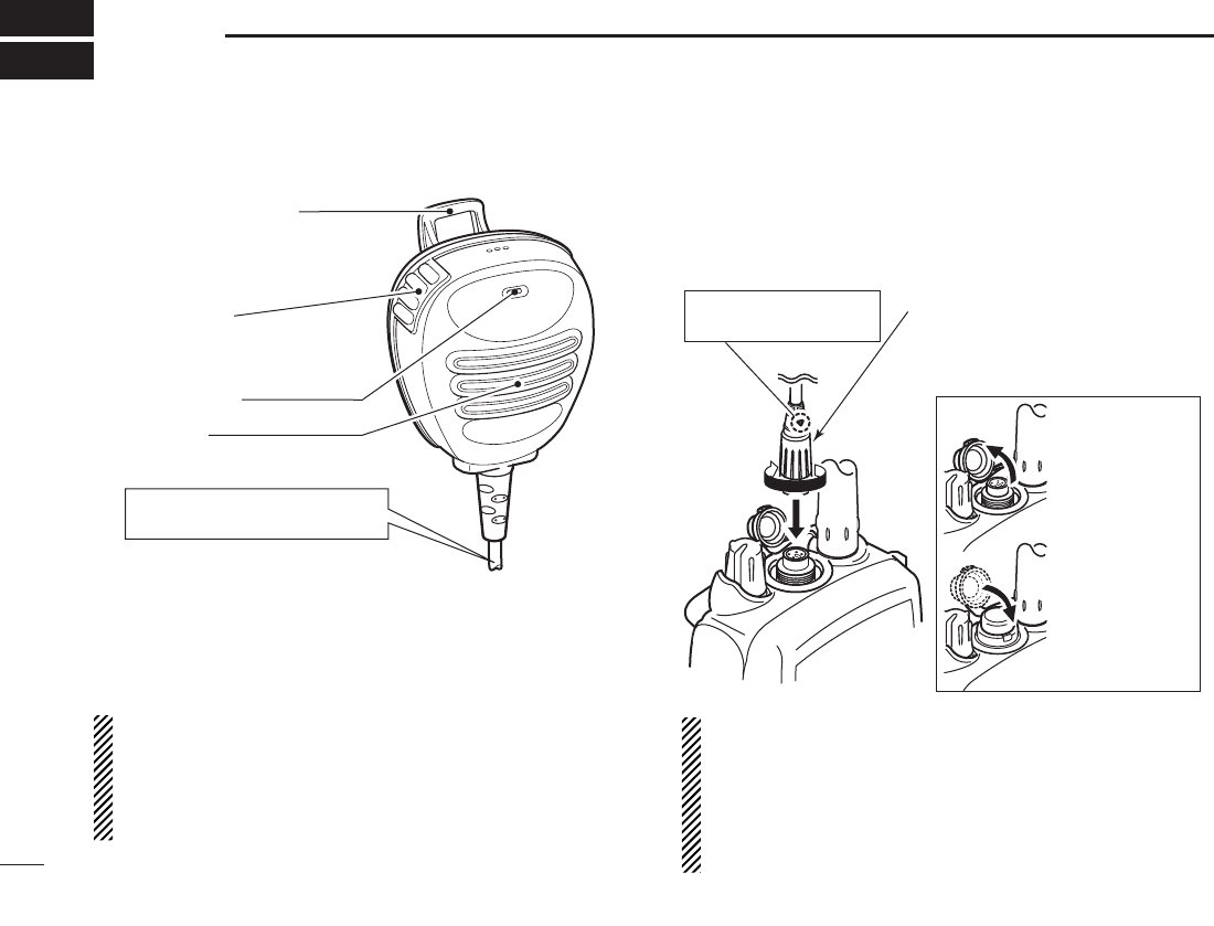
■HM-167descriptions
Alligator type clip
To attach the speaker-mic.
to your shirt or collar, etc.
PTT switch
Transmits during push.
Receives during release.
Microphone
Speaker
Tu rn the transceiver power OFF
when connecting the HM-167.
NEVER immerse the connector in water. If the connector
becomes wet, be sure to dry it BEFORE attaching it to the
transceiver.
NOTE: The microphone is located at the top of the speak-
er-microphone, as shown in the diagram above. To maxi-
mize the readability of your transmitted signal (voice), hold
the microphone approx. 2.5 cm (1 inch) from your mouth,
and speak in a normal voice level.
■ Attachment
Insert the speaker-mic connector onto the [SP MIC] con-
nector and carefully screw it tight, as shown in the diagram
below. Be careful not to cross-thread the connection.
Set the triangle mark
to the front side.
CAUTION: Attach the speaker-
microphone’s connector securely
to prevent accidental dropping, or
water intrusion in the connector.
Detaching:
Pull up the cap
in the direction
of the arrow to
detach it.
Attaching:
Attach the cap
in the direction
of the arrow
completely.
IMPORTANT: KEEP the transceiver’s [SP MIC] connec-
tor cap attached when the speaker-microphone is not in
use. Water will not get into the transceiver even if the
cover is not attached; however, the terminals (pins) will
become rusty, or the transceiver will function abnormally
if the connector has become wet.

37
12
TROUBLESHOOTING
1
2
3
4
5
6
7
8
9
10
11
12
13
14
15
16
PROBLEM POSSIBLE CAUSE SOLUTION REF.
The transceiver does not
turn ON.
pp.
25–27
p. 3
N o s o u n d f r o m t h e
speaker.
[SP MIC] connector.
[VOL] to set a suitable level.
[16•9] and [H/L•LOCK] to drain water
from the speaker.
[SP MIC] connector.
p. 11
p. 9
p. 12
—
Transmitting is impossible,
or high power can not be
selected.
receive only.
[H/L•LOCK] to select high power.
pp. 8, 9,
31
pp.
25–27
—
p. 9
The displayed channel
cannot be changed.
[H/L•LOCK] for 1 second to cancel the function. p. 10
Scan does not start. p. 15
No beeps.
SET mode.
p. 18
Self check error.
(Temperature)
+73°C; –31°F to +163°F (approx.).
Turn the power ON to check if the internal temperature
has returned to normal.
—
Self check error.
(Battery voltage)
more than 11 V.
—
Transmitting continuously
while not speaking when
using VOX function.
[] and [H/L•LOCK] to deactivate the VOX
function.
p. 12
p. 22
“CHARGE” comment
blinks
pp.
25–27

38
SPECIFICATIONS
13
•IC-M73
General D
Tx 156.025–157.425 MHz
Rx 156.050–163.275 MHz (USA and EXP versions)
Rx 156.300–162.025 MHz (AUS version)
FM (16K0G3E)
USA and EXP versions :
–20°C to +60°C (–4°F to +140°F)
AUS version : –10°C to +55°C
(approximately) Max. audio 0.5 A
7.4 V DC nominal (negative ground)
USA and EXP versions : ±10 ppm (–20°C to +60°C)
AUS version : ±10 ppm (–10°C to +55°C)
˘ nominal
52.5(W) × 125(H) × 30(D)mm
(Projections not included) : 2.0(W)
× 4.9(H) × 1.2(D) inches
(approximately) : 280 g/9.9 oz with BP-245N
Transmitter D
USA and EXP versions : 6 W/3 W/1 W
AUS version : 5 W (approximately)/1 W
modulation
(typical)
USA and EXP versions : –68 dBc
AUS version : 0.25 µW
Receiver D
USA and EXP versions : 0.22 µV (12 dB SINAD)
AUS version : –5 dBµ emf (20 dB SINAD)
(at threshold, typical)
USA and EXP versions : 0.35 µV
AUS version : –6 dBµ emf
USA and EXP versions : 70 dB (typical)
AUS version : 65 dB
Spurious response rejection ratio
:
USA and EXP versions : 70 dB (typical)
AUS version : 65 dB
USA and EXP versions : 70 dB (typical)
AUS version : 65 dB
8 ˘ load)
USA and EXP versions
:
0.35 W typical (External)
: 0.7 W typical (Internal)
AUS version : 0.2 W (External)
: 0.7 W typical at 1 kHz (Internal)
All stated specifications are subject to change without notice
or obligation.

39
13
SPECIFICATIONS
1
2
3
4
5
6
7
8
9
10
11
12
13
14
15
16
•IC-M73EURO
General D
Rx 156.000–163.425 MHz
FM (16K0G3E)
–15°C to +55°C
(5 W) 1.5 A
Tx (1 W) 0.7 A
Tx (0.5 W) 0.6 A
Rx Max. audio 0.45 A
7.4 V DC nominal (negative ground)
±1.5 kHz
˘ nominal
:
52.5(W) × 125(H) × 30(D) mm
(Projections not included)
(approximately) : 280 g with BP-245N
Transmitter D
5 W/1 W/0.5 W*
*German version only
modulation
: 0.25 µW
Receiver D
: –4 dBµ emf at 20 dB SINAD
(threshold) : –5 dBµ emf (typical)
Spurious response rejection ratio
: 70 dB
: 70 dB
8 ˘ load)
:
0.2 W (External)
0.7 W typical at 1 kHz (Internal)
All stated specifications are subject to change without notice
or obligation.

40
VHF MARINE CHANNEL LIST
14
CH Frequency (MHz) CH Frequency (MHz) CH Frequency (MHz) CH Frequency (MHz) CH Frequency (MHz) CH Frequency (MHz)
Transmit ReceiveTransmit ReceiveTransmit ReceiveTransmit ReceiveTransmit ReceiveTransmit Receive
01 156.050 160.650 11 156.550 156.550 21 157.050 161.650 61 156.075 160.675 71 156.575 156.575 81 157.075 161.675
02 156.100 160.700 12 156.600 156.600 22 157.100 161.700 62 156.125 160.725 72 156.625 156.625 82 157.125 161.725
03 156.150 160.750 13 156.650 156.650 23 157.150 161.750 63 156.175 160.775 73 156.675 156.675 83 157.175 161.775
04 156.200 160.800 14 156.700 156.700 24 157.200 161.800 64 156.225 160.825 74 156.725 156.725 84 157.225 161.825
05 156.250 160.850 15*2156.750 156.750 25 157.250 161.850 65 156.275 160.875 75*4156.775 156.775 85 157.275 161.875
06 156.300 156.300 16 156.800 156.800 26 157.300 161.900 66 156.325 160.925 76*4156.825 156.825 86 157.325 161.925
07 156.350 160.950 17*2156.850 156.850 27 157.350 161.950 67 156.375 156.375 77 156.875 156.875 87 157.375 157.375
P4*3161.425 161.425
88 157.425 157.425
08 156.400 156.400 18 156.900 161.500 28 157.400 162.000 68
69
156.425 156.425 78 156.925 161.525
09 156.450 156.450 19 156.950 161.550 37A*3157.850 157.850 156.475 156.475 79 156.975 161.575
10 156.500 156.500 20 157.000 161.600 60 156.025 160.625 70*1156.525 156.525 80 157.025 161.625
*1 DSC operation only.
*3 UK Marina Channels: M1=37A (157.850 MHz), M2=P4 (161.425 MHz) for U.K. version only
*2 Channels 15 and 17 may also be used for on-board communications provided the effective radiated power does not exceed 1 W,
and subject to the national regulations of the administration concerned when these channels are used in its territorial waters.
*4 The output power of channels 75 and 76 are limited to low power (1 W) only. The use of these channels should be restricted to
navigation-related communications only and all precautions should be taken to avoid harmful interference to channel 16, e.g.
by means geographical separation.
For IC-M73EURO D

41
14
VHF MARINE CHANNEL LIST
1
2
3
4
5
6
7
8
9
10
11
12
13
14
15
16
USA channels (for U.K. version only)
Frequency (MHz) Frequency (MHz) Frequency (MHz) Frequency (MHz) Frequency (MHz) Frequency (MHz)
Transmit ReceiveTransmit ReceiveTransmit ReceiveTransmit ReceiveTransmit ReceiveTransmit Receive
156.050 156.050 156.600 156.600 157.100 157.100 156.225 156.225 156.775 156.775
156.825 156.825
156.875 156.875 157.325 161.925
- - -- - - 156.650 156.650 157.150 157.150 156.275 156.275
156.925 156.925 157.325 157.325
156.150 156.150 156.700 156.700 157.200 161.800 156.325 156.325
156.975 156.975 157.375 161.975
- - -- - - 156.750 156.750 157.250 161.850 156.375 156.375
157.025 157.025 157.375 157.375
156.250 156.250 156.800 156.800 157.300 161.900 156.425 156.425
157.075 157.075 157.425 162.025
156.300 156.300 156.850 156.850 157.350 161.950 156.475 156.475
157.125 157.125 157.425 157.425
161.425 161.425
156.350 156.350 156.900 156.900 157.400 162.000 156.525 156.525
157.175 157.175
156.400 156.400 156.950 156.950 157.850 157.850 156.575 156.575
157.225 161.825
156.450 156.450 157.000 161.600 156.075 156.075 156.625 156.625
157.225 157.225
156.500 156.500 157.000 157.000 - - -- - -156.675 156.675
156.550 156.550 157.050 157.050 156.175 156.175 156.725 156.725
157.275 161.875
157.275 157.275
12
13*2
20A
21A
20
19A
18A
17*1
16
15*2
14
CH
22A
23A
- -
63A
61A
37A*4
28
27
26
25
24
CH
64A
65A
73
74
72
71
70*3
69
68
67*2
66A
CH
75*1
76*1
84
84A
83A
82A
81A
80A
79A
78A
77*1
CH
85
85A
P4*4
88A
88
87A
87
86A
86
CH
01A
- -
10
11
09
08
07A
06
05A
- -
03A
CH
NOTE: Simplex channels, 3, 21, 23, 61, 64, 81, 82 and 83 CANNOT be lawfully used by the general public in U.S.A. waters.
*1 Low power only.
*2 Momentary high power.
*3 DSC operation only.
*4 UK Marina Channels: M1=37A (157.850 MHz), M2=P4 (161.425 MHz) for U.K. version only
For IC-M73EURO D

42
14 VHF MARINE CHANNEL LIST
Channel number
USA CAN
Transmit
Receive
Frequency (MHz)
INT
Channel number Frequency (MHz)
USA CAN
Transmit
ReceiveINT
Channel number Frequency (MHz)
USA CAN
Transmit
ReceiveINT
Channel number Frequency (MHz)
USA CAN
Transmit
ReceiveINT
WX channel Frequency (MHz)
Transmit Receive
01 156.050 160.650
01A 156.050 156.050
02 156.100 160.700
03 156.150 160.750
03A 156.150 156.150
156.200 160.800
04A 156.200 156.200
156.250 160.850
05A 05A 156.250 156.250
06 06 156.300 156.300
156.350 160.950
07A 07A 156.350 156.350
08 08 156.400 156.400
09 09 156.450 156.450
10 10 156.500 156.500
11 11 156.550 156.550
12 12 156.600 156.600
13*13*156.650 156.650
14 14 156.700 156.700
15*15*156.750 156.750
16 16 156.800 156.800
17*17*156.850 156.850
156.900 161.500
18A 18A 156.900 156.900
01
02
03
04
05
06
07
08
09
10
11
12
13
14
15*
16
17
18
156.950 161.550
19A 19A 156.950 156.950
20 20*157.000 161.600
21 157.050 161.650
21A 21A 157.050 157.050
157.100 161.700
22A 22A 157.100 157.100
23 157.150 161.750
23A 157.150 157.150
24 24 157.200 161.800
25 25 157.250 161.850
26 26 157.300 161.900
27 27 157.350 161.950
28 28 157.400 162.000
60 156.025 160.625
156.075 160.675
61A 61A 156.075 156.075
156.125 160.725
62A 156.125 156.125
156.175 160.775
63A 156.175 156.175
64 156.225 160.825
64A 64A 156.225 156.225
19
20
21
22
23
24
25
26
27
28
60
61
62
63
64
20A 157.000 157.000
66A 66A*
156.325 160.925
67*67 156.375 156.375
68 68 156.425 156.425
69 69 156.475 156.475
70 70 156.525
71 71 156.575 156.575
72 72 156.625 156.625
73 73 156.675 156.675
74 74 156.725 156.725
77*77*156.875 156.875
156.925 161.525
78A 78A 156.925 156.925
156.975 161.575
79A 79A 156.975 156.975
157.025 161.625
80A 80A 157.025 157.025
157.075 161.675
81A 81A 157.075 157.075
157.125 161.725
82A 82A 157.125 157.125
66
67
68
69
70
71
72
73
74
77
78
79
80
81
82
156.325 156.32566A
85 85 157.275 161.875
85A 157.275 157.275
86 86 157.325 161.925
86A 157.325 157.325
87 87 157.375 161.975
87A 157.375 157.375
88 88 157.425 162.025
88A 157.425 157.425
85
86
87
88
21b Rx only
Rx only
161.650
25b Rx only 161.850
28b Rx only 162.000
83b Rx only 161.775
4
1 RX only 162.550
2 RX only 162.400
3 RX only 162.475
5 RX only 162.450
6 RX only 162.500
7 RX only 162.525
8 RX only 161.650
9 RX only 161.775
10 RX only 163.275
RX only 162.425
156.275 160.875
65A 65A 156.275 156.275
65
65A 84A
83 157.175 161.775
83A 83A 157.175 157.175
84 84 157.225 161.825
83
84
157.225 157.225
*Low power only.
NOTE: Simplex channels 3, 21, 23, 61, 64, 81, 82 and 83 CANNOT be lawfully used by the general public in USA waters.
The programmed channels are differ according to versions.
For IC-M73 D

43
15
OPTIONS
1
2
3
4
5
6
7
8
9
10
11
12
13
14
15
16
D BATTERY CASE AND PACK
•BP-245NLi-Ion B AT T E RY P A C K
The same as supplied with the transceiver.
Voltage : 7.4 V
Capacity : 1900 mAh (minimum)/2000 mAh (typical)
D CHARGERS
•BC-210D E S K TO P C H A R G E R +BC-123SA/SEA C A D A P T E R
For rapid charging of battery packs. The same as supplied with the
transceiver. An AC adapter is supplied with the charger depending
on versions. Charging time: approx. 3 to 4 hours
•BC-197M U L T I -C H A R G E R +AD-129C H A R G E R A D A P T E R (6 pcs.)
+BC-157SA C A D A P T E R
For rapid charging of up to 6 battery packs (six AD-129’s are
required) simultaneously. An AC adapter should be purchased
separately. Charging time: approx. 3 to 4 hours.
D BELT CLIPS
•MB-103B E LT C L I P
The same as supplied with the transceiver.
•MB-86S W I V E L B E LT C L I P
Belt clip for swivel type.
•MB-96NL E AT H E R B E LT H A N G E R
D DC CABLES
•CP-25HC I G A R E T T E L I G H T E R C A B L E
Charges the battery pack through a 12 V cigarette lighter socket.
(For BC-210)
•OPC-515L/OPC-656D C P O W E R C A B L E S
Charges the battery pack using 13.8 V power source instead of the
AC adapter.
OPC-515L: For BC-210
OPC-656 : For BC-197
D OTHER OPTIONS
•HM-167S P E A K E R -M I C R O P H O N E
Full sized waterproof speaker-microphone including alligator type
clip to attach to your shirt or collar, etc.
•HM-202S P E A K E R -M I C R O P H O N E
•FA-S64VF L E X I B L E A N T E N N A
Same as that supplied with the transceiver.
Icom optional equipment is designed for optimal perform-
ance when used with this transceiver. We are not respon-
sible for the transceiver being damaged or any accident
caused when using non-Icom optional equipment.
Available or applicable options may differ according to
countries. Ask your authorized dealer for details.

44
MEMO

45
MEMO
1
2
3
4
5
6
7
8
9
10
11
12
13
14
15
16

46
MEMO

47
MEMO
1
2
3
4
5
6
7
8
9
10
11
12
13
14
15
16
1-1-32 Kamiminami, Hirano-ku, Osaka 547-0003, Japan
A-7070D-1EX
Printed in Japan
© 2013 Icom Inc.
< Intended Country of Use >
AT
FI
IT
PL
GB
RO
BE
FR
LV
PT
IS
TR
CY
DE
LT
SK
LI
HR
CZ
GR
LU
SI
NO
DK
HU
MT
ES
CH
EE
IE
NL
SE
BG
Printed on recycled paper with soy ink.