ICOM orporated 349500 VHF Marine Transceiver User Manual IC M73 M73EURO 3 indd
ICOM Incorporated VHF Marine Transceiver IC M73 M73EURO 3 indd
Contents
- 1. User Manual
- 2. Updated Manual
- 3. User Manual_Updated
User Manual_Updated
INSTRUCTION MANUAL
iM73
VHF MARINE TRANSCEIVER
This device complies with Part 15 of the FCC Rules. Opera-
tion is subject to the condition that this device does not cause
harmful interference.
iM73EURO
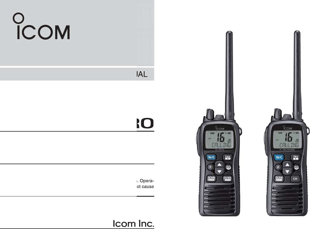
IC-M73 IC-M73EURO
(These transceivers use the FA-S64V)

i
FOREWORD
Thank you for purchasing this Icom product. The IC-M73/IC-
M73EURO VHF MARINE TRANSCEIVER is designed and built
with Icom’s state of the art technology and craftsmanship.
With proper care, this product should provide you with years
of trouble-free operation.
IMPORTANT
READ ALL INSTRUCTIONS carefully and completely
before using the transceiver.
SAVE THIS INSTRUCTION MANUAL — This in-
struction manual contains important operating instructions
for the IC-M73/IC-M73EURO.
EXPLICIT DEFINITIONS
WORD DEFINITION
RDANGER! Personal death, serious injury or an ex-
plosion may occur.
RWARNING! Personal injury, fire hazard or electric
shock may occur.
CAUTION Equipment damage may occur.
NOTE If disregarded, inconvenience only. No risk
of personal injury, fire or electric shock.
FEATURES
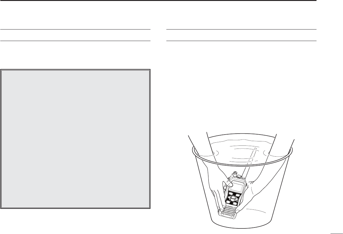
Submersible construction
Built tough to withstand the punishing marine environ-
ment, the IC-M73/IC-M73EURO’s submersible construc-
tion meets IPX8 ratings of the International Standard IEC
60529 (2001).
In addition, the speaker grill structure with a water self-
draining Aquaquake function is helpful for easily removing
rain or seawater.
Dualwatch and Tri-watch functions
Convenient functions that allow you to monitor the distress
channel (Ch 16) while receiving one other channel of your
choice (Dualwatch), or while receiving one other channel
of your choice and the Call channel (Tri-watch*). See page
16 for details.
* May not be available depending on the transceiver version.
Voice recorder function
IC-M73/IC-M73EURO has a voice recorder function* which
can automatically, or manually, record the received signal.
The automatic (60 seconds) and manual (30 seconds) re-
cordings are recorded separately into memory in the trans-
ceiver.
* May not be available depending on the transceiver version.
Bass booster function
The TX/RX bass booster functions* boosts the frequen-
cies to increase the bass level, if desired.
* May not be available depending on the transceiver version.

ii
RDANGER! NEVER short the terminals of the battery
pack.
RDANGER! Use and charge only specified Icom battery
packs with Icom radios or Icom chargers. Only Icom battery packs
are tested and approved for use with Icom radios or charged with
Icom chargers. Using third-party or counterfeit battery packs or
chargers may cause smoke, fire, or cause the battery to burst.
RWARNING! NEVER connect the transceiver to an AC
outlet. This may pose a fire hazard or result in an electric shock.
RWARNING! NEVER hold the transceiver so that the an-
tenna is closer than 2.5 cm (1 inch) from exposed parts of the
body, especially the face or eyes, while transmitting. The trans-
ceiver will perform best if the microphone is 5 to 10 cm (2 to 4
inches) away from the lips and the transceiver is vertical.
CAUTION: NEVER connect the transceiver to a power
source other than the products specified by Icom. Such a connec-
tion will ruin the transceiver.
CAUTION: MAKE SURE the flexible antenna and bat-
tery pack are securely attached to the transceiver, and that the
antenna and battery pack are dry before attachment. Exposing
the inside of the transceiver to water will result in serious damage
to the transceiver.
BE CAREFUL! The transceiver meets IPX8 requirements
for waterproof protection. However, once the transceiver has
been dropped, waterproof protection cannot be guaranteed be-
cause of possible damage to the transceiver's case or the water-
proof seal.
DO NOT use or place the transceiver in direct sunlight or in
areas with temperatures below –20°C (–4°F) or above +60°C
(+140°F) for the EXP/USA versions, below –15°C (+5°F) or
above +55°C (+131°F) for the CHN/EUR/FRG/HOL/UK versions,
and below –10°C (+14°F) or above +55°C (+131°F) for the AUS
versions.
DO NOT use harsh solvents such as benzine or alcohol when
cleaning, as they will damage the transceiver surfaces.
DO NOT push [PTT] when not actually intending to transmit.
DO NOT modify the transceiver. The transceiver warranty does
not cover any problems caused by unauthorized modification.
DO NOT operate the transceiver near unshielded electrical
blasting caps or in an explosive atmosphere.
KEEP the transceiver out of the reach of children.
KEEP the transceiver at least 0.9 meter (3.0 feet) away from
your vessel’s magnetic navigation compass.
PRECAUTIONS
Icom, Icom Inc. and the Icom logo are registered trademarks of Icom
Incorporated (Japan) in Japan, the United States, the United Kingdom,
Germany, France, Spain, Russia and/or other countries.

iii
RADIO OPERATOR WARNING
Your Icom radio generates RF electromagnetic energy during
transmit mode. This radio is designed for and classified as
“General Population Use” in an uncontrolled environment.
This radio has been evaluated for compliance at the distance
of 2.5 cm (1 inch) with the FCC and IC RF exposure limits for
“
General Population Use.
” In addition, your Icom radio com-
plies with the following Standards and Guidelines with regard
to RF energy and electromagnetic energy levels and evalua-
tion of such levels for exposure to humans:
s&##/%4"ULLETIN%DITION3UPPLEMENT#%VALUATING#OMPLI-
ance with FCC Guidelines for Human Exposure to Radio Frequency
Electromagnetic Fields.
s!MERICAN.ATIONAL3TANDARDS)NSTITUTE#)%%%3TANDARD
for Safety Levels with Respect to Human Exposure to Radio Frequency
Electromagnetic Fields, 3 kHz to 300 GHz.
s!MERICAN.ATIONAL3TANDARDS)NSTITUTE#)%%%2ECOM-
mended Practice for the Measurement of Potentially Hazardous Electro-
magnetic Fields– RF and Microwave.
s4HEFOLLOWINGACCESSORIESAREAUTHORIZEDFORUSEWITHTHISPRODUCT5SEOF
accessories other than those specified may result in RF exposure levels
exceeding the FCC
and IC
requirements for wireless RF exposure.; Belt
Clip (MB-103), Rechargeable Li-ion Battery Pack (BP-245H).
To ensure that your expose to RF electromagnetic en-
ergy is within the FCC
and IC
allowable limits for general
population use, always adhere to the following guide-
lines:
sDO NOT operate the radio without a proper antenna attached, as this
may damaged the radio and may also cause you to exceed FCC
and
IC
RF exposure limits. A proper antenna is the antenna supplied with
this radio by the manufacturer or antenna specifically authorized by the
manufacturer for use with this radio.
sDO NOT transmit for more than 50% of total radio use time (“50% duty
cycle”). Transmitting more than 50% of the time can cause FCC
and IC
RF exposure compliance requirements to be exceeded. The radio is
transmitting when the “transmit indicator” appears on the LCD. You can
cause the radio to transmit by pressing the “PTT” switch.
sALWAYS keep the antenna at least 2.5 cm (1 inch) away from the body
when transmitting and only use the Icom belt clip which is listed on page
43 when attaching the radio to your belt, etc., to ensure FCC
and IC
RF
exposure compliance requirements are not exceeded. To provide the re-
cipients of your transmission the best sound quality, hold the antenna at
least 5 cm (2 inches) from your mouth, and slightly off to one side.
The information listed above provides the user with the information needed
to make him or her aware of RF exposure, and what to do to assure that this
radio operates with the FCC
and IC
RF exposure limits of this radio.
Electromagnetic Interference/Compatibility
During transmissions, your Icom radio generates RF energy that can possibly
cause interference with other devices or systems. To avoid such interference,
turn off the radio in areas where signs are posted to do so. DO NOT operate
the transmitter in areas that are sensitive to electromagnetic radiation such as
hospitals, aircraft, and blasting sites.
WARNING
CAUTION

iv
AVERTISSEMENT POUR LES OPÉRATEURS RADIO
Votre radio Icom produit une énergie électromagnétique
de radiofréquences (RF), en mode de transmission. Elle
est conçue pour une «utilisation grand public», dans un
environnement non contrôlé. Cet appareil a été évalué et
jugé conforme, à 2,5 cm, aux limites d'exposition aux RF
de la FCC et d’IC, pour une «utilisation grand public». En
outre, votre radio Icom satisfait les normes et directives
qui suivent en matière de niveaux d'énergie et d'énergie
électromagnétique de RF et d'évaluation de tels niveaux
en ce qui concerne l'exposition humaine :
s3UPPL£MENT # £DITION DU "ULLETIN /%4 DE LA &## i%VALUATING
Compliance with FCC Guidelines for Human Exposure to Radio Frequency
Electromagnetic Fields».
s.ORME DE L!MERICAN .ATIONAL 3TANDARDS )NSTITUTE !.3) )%%% #
1992 sur les niveaux de sécurité compatibles avec l’exposition humaine aux
champs électromagnétiques de radiofréquences (3 kHz à 300 GHz).
s.ORMEDEL!.3))%%%#SURLAM£THODED£VALUATIONRECOMMAN-
dée du champ magnétique potentiellement dangereux des radiofréquences
et des micro-ondes.
s,ES ACCESSOIRES QUI SUIVENT SONT APPROUV£S POUR UNE UTILISATION AVEC CE
produit. L'utilisation d'accessoires autres que ceux précisés peut entraîner
des niveaux d'exposition aux RF supérieures aux limites établies par la FCC
et d’IC en matière d'exposition aux RF sans fil; attache pour ceinture (MB-
103), bloc-piles rechargeable au lithium-ion (BP-245H).
CAUTION
Afin de vous assurer que votre exposition à une
énergie électromagnétique de RF se situe dans
les limites permises par la FCC et d’IC pour une
utilisation grand public, veuillez en tout temps
respecter les directives suivantes :
sNE PAS faire fonctionner la radio sans qu'une antenne appropriée y soit
fixée, car ceci risque d'endommager la radio et causer une exposition
supérieure aux limites établies par la FCC et d’IC. L'antenne appropriée
est celle qui est fournie avec cette radio par le fabricant ou une antenne
spécialement autorisée par le fabricant pour être utilisée avec cette radio.
s NE PAS émettre pendant plus de 50% du temps total d'utilisation de
l'appareil («50% du facteur d'utilisation»). Émettre pendant plus de 50% du
temps total d'utilisation peut causer une exposition aux RF supérieure aux
limites établies par la FCC et d’IC. La radio est en train d’émettre lorsque le
témoin du mode de transmission s'affiche sur l'écran ACL. La radio émettra
si vous appuyez sur le bouton du microphone.
s TOUJOURS tenir l'antenne éloignée d'au moins 2,5 cm de votre corps
au moment d'émettre et utiliser uniquement l'attache pour ceinture Icom
illustrée à la p. 43, lorsque vous attachez la radio à votre ceinture, ou à
autre chose, de façon à vous assurer de ne pas provoquer une exposition
aux RF supérieure aux limites fixées par la FCC et d’IC. Pour offrir à vos
interlocuteurs la meilleure qualité de transmission possible, tenez l'antenne
à au moins 5 cm de votre bouche et légèrement de côté.
Les renseignements ci-dessus fournissent à l'utilisateur toute l'information
nécessaire sur l'exposition aux RF et sur ce qu'il faut faire pour assurer que
cette radio fonctionne en respectant les limites d'exposition aux RF établies
par la FCC et d’IC.
Interférence électromagnétique et compatibilité
En mode de transmission, votre radio Icom produit de l'énergie de RF qui
peut provoquer des interférences avec d'autres appareils ou systèmes. Pour
éviter de telles interférences, mettez la radio hors tension dans les secteurs
où une signalisation l’exige. NE PAS faire fonctionner l'émetteur dans des
secteurs sensibles au rayonnement électromagnétique tels que les hôpitaux,
les aéronefs et les sites de dynamitage.
AVERTISSEMENT
MISE EN GARDE

v
COUNTRY CODE LIST
s)3/
Country Codes Country Codes
1
2
3
4
5
6
7
8
9
10
11
12
13
14
15
16
17
Austria
Belgium
Bulgaria
Croatia
Czech Republic
Cyprus
Denmark
Estonia
Finland
France
Germany
Greece
Hungary
Iceland
Ireland
Italy
Latvia
AT
BE
BG
HR
CZ
CY
DK
EE
FI
FR
DE
GR
HU
IS
IE
IT
LV
18
19
20
21
22
23
24
25
26
27
28
29
30
31
32
33
Liechtenstein
Lithuania
Luxembourg
Malta
Netherlands
Norway
Poland
Portugal
Romania
Slovakia
Slovenia
Spain
Sweden
Switzerland
Turkey
United Kingdom
LI
LT
LU
MT
NL
NO
PL
PT
RO
SK
SI
ES
SE
CH
TR
GB
FOR CLASS A UNINTENTIONAL RADIATORS
This equipment has been tested and found to comply with the
limits for a Class A digital device, pursuant to part 15 of the
FCC Rules. These limits are designed to provide reasonable
protection against harmful interference when the equipment
is operated in a commercial environment. This equipment
generates, uses, and can radiate radio frequency energy
and, if not installed and used in accordance with the instruc-
tion manual, may cause harmful interference to radio commu-
nications. Operation of this equipment in a residential area is
likely to cause harmful interference in which case the user will
be required to correct the interference at his own expense.
CAUTION: Changes or modifications to this device, not ex-
pressly approved by Icom Inc., could void your authority to
operate this device under FCC regulations.
FCC INFORMATION
vi
IN CASE OF EMERGENCY
If your vessel requires assistance, contact other vessels and
the Coast Guard by sending a distress call on Channel 16.
MUSING CHANNEL 16
DISTRESS CALL PROCEDURE
1. “MAYDAY MAYDAY MAYDAY.”
2. “THIS IS ...........................” (name of vessel)
3. Say your call sign or other indication of the
vessel.
4. “LOCATED AT ..................... ” (your position)
5. State the nature of the distress and
assistance required.
6. Give any other information which might
facilitate the rescue.
RECOMMENDATION
CLEAN THE TRANSCEIVER THOROUGHLY WITH FRESH
WATER after exposure to saltwater, and dry it before opera-
tion. Otherwise, the transceiver’s keys, switches and control-
lers may become inoperable due to salt crystallization.
NOTE: DO NOT wash the transceiver in water if there is any
reason to suspect the waterproofing may not be effective.
For example, in cases where the transceiver/battery pack is
cracked or broken, or has been dropped, or when the battery
pack is detached from the transceiver.

vii
TABLE OF CONTENTS
FOREWORD .....................................................................................i
IMPORTANT ...................................................................................... i
EXPLICIT DEFINITIONS ...................................................................i
FEATURES ........................................................................................i
PRECAUTIONS ................................................................................ ii
RADIO OPERATOR WARNING ...................................................... iii
AVERTISSEMENT POUR LES OPÉRATEURS RADIO .................. iv
FCC INFORMATION ........................................................................ v
COUNTRY CODE LIST .................................................................... v
IN CASE OF EMERGENCY ............................................................ vi
RECOMMENDATION ...................................................................... vi
TABLE OF CONTENTS .................................................................. vii
OPERATING RULES ..................................................................
2 SUPPLIED ACCESSORIES AND ATTACHMENTS ...............2n
N Supplied accessories ...............................................................2
N Attachments .............................................................................2
PANEL DESCRIPTION ...........................................................4–7
N Front, top and side panels .......................................................4
N Function display .......................................................................6
4 BASIC OPERATION .............................................................8n
N Channel selection ....................................................................8
N Receiving and transmitting ....................................................11
N Call channel programming .....................................................12
N Lock function ..........................................................................12
N Monitor function .....................................................................12
N Adjusting the squelch level ....................................................13
N AquaQuake water draining function .......................................13
5 SCAN OPERATION (Except for the Dutch version) ............4n
N Scan types .............................................................................14
N Setting Favorite channels ......................................................15
N Starting a scan .......................................................................15
DUALWATCH/TRI-WATCH .......................................................
N Description .............................................................................16
N Operation ...............................................................................16
7 FUNCTION MODE OPERATION ........................................ 7–24
N About the function mode ........................................................17
N Manual recording function (Depending on versions) .............18
N
Automatic recording function (Depending on versions)
.............19
N Play back function (Depending on versions) ..........................20
N Channel naming function .......................................................21
N Opening comment entry function ...........................................22
N ATIS code programming
(For only the Dutch and German versions)
............................ 23
N Backlight function ...................................................................24
8 SET MODE ..........................................................................25n
N SET mode programming ........................................................25
N SET mode items ....................................................................26
9 BATTERY CHARGING .......................................................n
N Battery cautions .....................................................................31
N Supplied battery charger .......................................................33
N Optional battery chargers ......................................................34
OPTIONAL SWIVEL BELT CLIP ..............................................5
N Attaching ................................................................................35
N Detaching...............................................................................35
OPTIONAL SPEAKER-MICROPHONE ....................................
N HM-167 descriptions ..............................................................36
N Attaching ................................................................................36
TROUBLESHOOTING ..............................................................7
SPECIFICATIONS ...............................................................n
VHF MARINE CHANNEL LIST ...........................................4–42
OPTIONS .................................................................................. 4
INDEX .......................................................................................44–45

1
1
OPERATING RULES
2
4
5
7
8
9
DPriorities
s2EADALLRULES AND REGULATIONS PERTAINING TO CALL PRIORITIES
and keep an up-to-date copy handy. Safety and distress
calls take priority over all others.
s9OUMUSTMONITOR#HANNELWHENYOUARENOTOPERATING
on another channel.
s&ALSEORFRAUDULENTDISTRESSCALLSAREPROHIBITEDUNDERLAW
DPrivacy
s)NFORMATIONOVERHEARDBUTNOTINTENDEDFORYOUCANNOTLAW-
fully be used in any way.
s)NDECENTORPROFANELANGUAGEISPROHIBITED
DRadio licenses
3()034!4)/.,)#%.3%
You may require a current radio station license before using
the transceiver. It is unlawful to operate a ship station which is
not licensed, but required to be.
If required, contact your dealer or the appropriate govern-
ment agency for a Ship-Radiotelephone license application.
This government-issued license states the call sign which is
your craft’s identification for radio purposes.
/0%2!4/23,)#%.3%
A Restricted Radiotelephone Operator Permit is the license
most often held by small vessel radio operators when a radio
is not required for safety purposes.
If required, the Restricted Radiotelephone Operator Permit
must be posted or kept with the operator. If required, only a
licensed radio operator may operate a transceiver.
However, non-licensed individuals may talk over a transceiver
if a licensed operator starts, supervises, ends the call and
makes the necessary log entries.
A current copy of the applicable government rules and regu-
lations is only required to be on hand for vessels in which
a radio telephone is compulsory. However, even if you are
not required to have these on hand it is your responsibility to
be thoroughly acquainted with all pertinent rules and regula-
tions.
NOTE: Even though the transceiver is capable of opera-
tion on VHF marine channels 3, 21, 23, 61, 64, 81, 82 and
83, according to FCC regulations these simplex channels
cannot be lawfully used by the general population in USA
waters.
2
SUPPLIED ACCESSORIES AND ATTACHMENTS
2
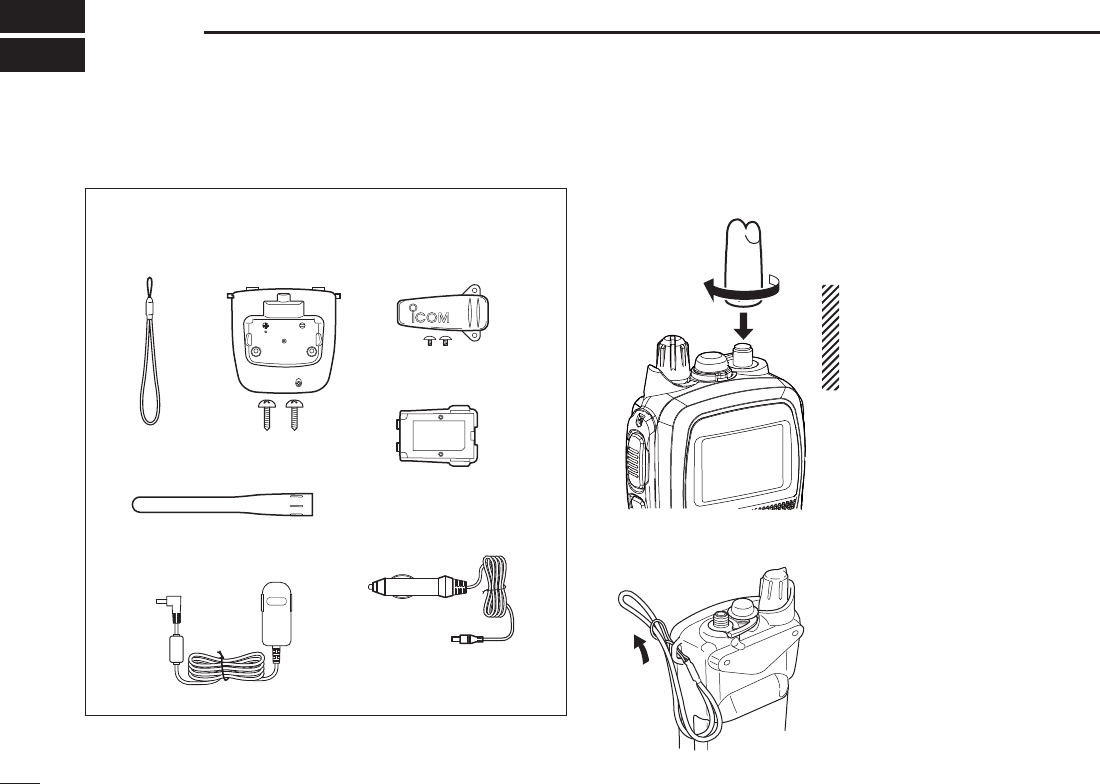
N Supplied accessories N Attachments
DFlexible antenna
Connect the supplied flexible
antenna to the antenna connector.
CAUTION:
s.%6%2 carry the transceiver
by holding the antenna.
s4RANSMITTINGWITHOUTANANTENNA
may damage the transceiver.
DHandstrap
Pass the handstrap through the
loop on the top corner of the
transceiver, as illustrated to the
left. This facilitates carrying the
transceiver.
Flexible antenna*
Cigarette lighter cable*
Handstrap Battery Charger
(with two screws)
Belt clip
(with two screws)
Li-ion battery pack
AC adapter*
* Not supplied or different type may be supplied depending on the
transceiver version.
3
2
SUPPLIED ACCESSORIES AND ATTACHMENTS
2
4
5
7
8
9
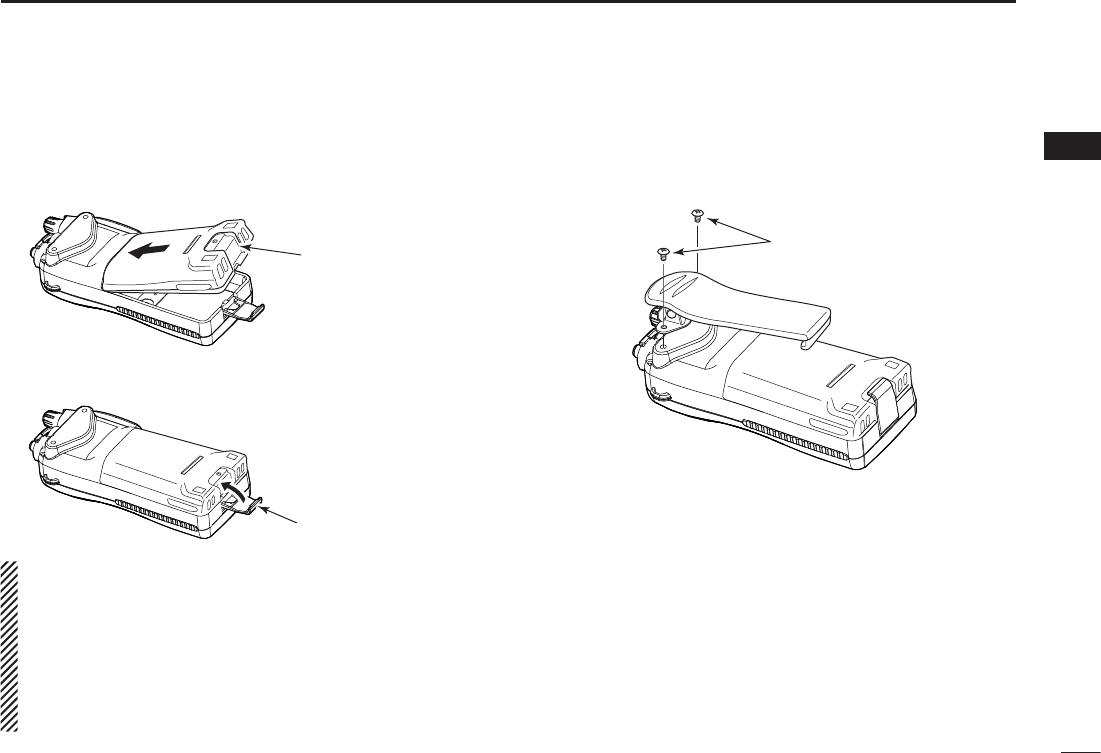
DBattery pack
Attach the battery pack into the transceiver. q
Battery pack
Lock the battery pack with the latch. w
Latch
CAUTION:
NEVER remove or attach the battery pack when the trans-
ceiver is wet or soiled. This may result in water or dust get-
ting into the transceiver and battery pack, and may result
in them being damaged.
Be careful! The latch is tightly locked, so use caution when
releasing it. DO NOT use your finger nail. Use the edge of
a coin or screwdriver tip to carefully release it.
DBelt clip
Attach the belt clip to the transceiver.
Supplied screws
4
PANEL DESCRIPTION
3
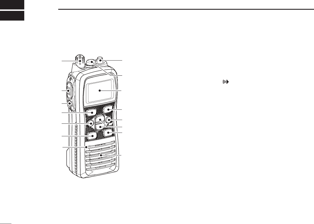
N Front, top and side panels
q
w
e
y
t
r
Microphone
!2
!1
!0
o
u
i
Speaker
Function
display (p. 6)
q VOLUME CONTROL [VOL]
Turns ON power and adjusts the audio level.
w PTT SWITCH [PTT]
Hold down to transmit; release to receive.
e MONITOR KEY []
s-ANUALLYOPENSTHESQUELCHTOMONITORTHECHANNELWHILE
held down. (p. 12)
s0USHTHISSWITCHTHENADJUSTTHESQUELCHLEVELWITH;Y]/
[Z]. (p. 13)
s7HILEHOLDINGDOWNTHISSWITCHTURNTHE/.POWERTO
enter the SET mode. (p. 25)
r #(!..%,+%9;#=
s3ELECTS#HANNELWHENPUSHEDP
s
Selects the Call channel when pushed for 1 second.
(p. 8)
s
Enters the Call channel write mode when the Call channel
is selected and this key is held down for 3 seconds. (p. 12)
t FUNCTION KEY [F]
s%NTERSTHE&UNCTIONMODEWHENPUSHEDP
s4HE!QUA1UAKEFUNCTIONISACTIVATEDWHENHELDDOWNFOR
1 second. (p. 13)
s7HILEHOLDINGDOWNTHISKEYTURN/.THEPOWERTOENTER
the recording counter mode.

5
3
PANEL DESCRIPTION
2
4
5
7
8
9
y 3#!.+%9;3#!.s$5!,=
s3TARTSANDSTOPSNORMALORPRIORITYSCANWHENPUSHED
(pp. 14, 15)
s%NTERSTHE7ATCHMODEWHENHELDDOWNFORSECOND
(p. 16)
u CHANNEL/WEATHER CHANNEL KEY
;#(78s5)#=)#-;#(=)#%52/
s3ELECTSANDTOGGLESTHEREGULARCHANNELSANDWEATHER
channel* when pushed. (pp. 9, 10)
s3ELECTS THE 53! )NTERNATIONAL #ANADIAN OR !4)3
channel group* when held down for 1 second. (p. 9)
- The function display shows which channel group is
active.
s0USHTORETURNTOTHEDISPLAYBEFOREYOUSELECTEDTHE
channel when the priority channel or the Call channel is
selected.
* Selectable contents differ depending on the transceiver version.
NOTE: ;#(78s5)#= and [CH] are described as [CH/
78s5)#= in this instruction manual.
i CHANNEL UP/DOWN KEYS [Y]/[Z]
s3ELECTSTHEOPERATINGCHANNELPPn
s3ELECTSTHE3%4MODEOPTIONOFTHEITEMP
s
Selects the SET mode item when pushed along with []
.
(p. 25)
s#HECKS &AVORITE 4!' CHANNELS OR CHANGES THE
scanning direction during a scan. (p. 15)
s3ELECTSTHE&UNCTIONMODEITEMP
o 42!.3-)40/7%2,/#++%9;(,s,/#+=
s3ELECTSHIGHMIDDLEORLOWPOWERWHENPUSHEDP
s4OGGLESTHELOCKFUNCTION/./&&WHENHELDDOWNFOR
second. (p. 12)
!0 &!6/2)4%4!'+%9;&!6s(]
s0USHTHISKEYTOSEQUENTIALLYSELECTTHE&AVORITE4!'
channels, while ignoring untagged channels, in a channel
group. (p. 15)
s(OLDDOWNFORSECOND TOSETOR CLEARTHEDISPLAYED
channel as a Favorite (TAG) channel. (p. 15)
s7HILEHOLDINGDOWNTHISKEYTURN/.POWERTOCLEAROR
set all Favorite (TAG) channels in the selected channel
group. (p. 15)
!1 SPEAKER-MICROPHONE CONNECTOR [SP MIC]
Connects the optional external speaker-microphone.
(p. 36)
NOTE: Attach the [SP MIC] cap when the optional
speaker-microphone is not used.
!2 ANTENNA CONNECTOR
Connects the supplied antenna. (p. 2)
6
3PANEL DESCRIPTION
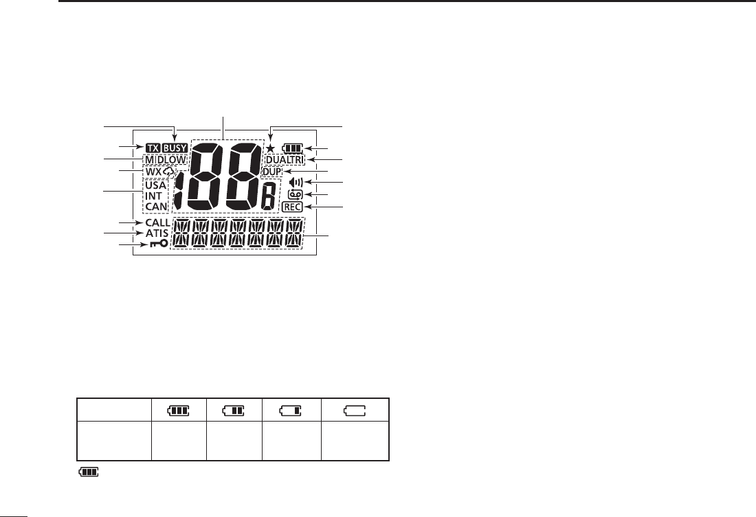
N Function display
q
e
t
i
r
y
o
u
!0
!2
!3
!5
!4
!6
!7
!1
w
q CHANNEL NUMBER READOUT
s)NDICATESTHESELECTEDOPERATINGCHANNELNUMBER
s)NTHE3%4MODEINDICATESTHESELECTEDVALUE
w FAVORITE CHANNEL ICON (p. 15)
Appears when a Favorite (TAG) channel is selected.
e BATTERY ICON
Indicates remaining battery power.
Indication
Full Middle Low No battery
(Charging required)
Battery level
blinks when the battery is overcharged (or over voltage).
r DUALWATCH/TRI-WATCH ICONS (p. 16)
“DUAL” blinks during dualwatch; “TRI” blinks during tri-
watch.
t DUPLEX ICON (p. 9)
Appears when a duplex channel is selected.
y MONITOR ICON (p. 12)
Appears when the monitor function is activated.
u AUTOMATIC RECORDING ICON (p. 19)
Appears when the automatic recording is activated. This
may not appear depending on the transceiver version.
i RECORDING ICON
Appears while the receiving audio is recording. (pp. 18, 19)
This may not appear depending on the transceiver ver-
sion.
o CHANNEL NAME FIELD
s)NDICATES OR SCROLLS THE OPERATING CHANNEL NAME COMMENT OR
ATIS code*. (pp. 21–23)
*For only the Dutch and German versions.
s)NTHE3%4AND&UNCTIONMODEINDICATESORSCROLLSTHESELECTED
item. (pp. 25–30)
s “SCAN 16” is displayed during a Priority scan; “SCAN” appears
during a Normal scan. (p. 15)
!0 LOCK ICON (p. 12)
Appears when the lock function is activated.

7
3
PANEL DESCRIPTION
2
4
5
7
8
9
!1 ATIS ICON (pp. 9, 23)
Appears when the channel group, in which ATIS function
is activated, is selected or while programming an ATIS
code.
s&ORONLYTHE(/,AND&2'VERSIONS
!2 CALL CHANNEL ICON (p. 8)
Appears when the Call channel is selected.
!3 CHANNEL GROUP ICON (p. 9)
“USA” appears when U.S.A.*1; “INT” appears when
International; “CAN” appears when the Canadian*2; “ATIS”
appears when ATIS*3 channel group is selected.
*
1Only USA, UK, EXP, CHN and AUS versions.
*
2Only USA, EXP and CHN versions.
*
3Only HOL version.
!
4 WEATHER CHANNEL/WEATHER ALERT ICONS* (p. 10)
sh” appears when the Weather channel group is
selected.
sh” appears when the Weather alert function is
activated.
*Selectable on only the USA, EXP, and AUS versions.
!5 TRANSMIT POWER ICONS (p. 11)
sh,/7vAPPEARSWHENLOWPOWERISSELECTED
sh-)$vAPPEARSWHENMIDPOWERISSELECTED
s.OINDICATIONAPPEARSWHENHIGHPOWERISSELECTED
!6 TRANSMIT ICON (p. 11)
Appears during transmit.
!7 BUSY ICON (pp. 11, 12)
Appears when a signal is received, or the squelch opens.

8
BASIC OPERATION
4
N Channel selection
IMPORTANT!: Prior to using the transceiver for the first
time, fully charge the battery pack. This will help maximize
the capability and life of the battery. To avoid damage to
the transceiver, turn OFF the radio while charging.
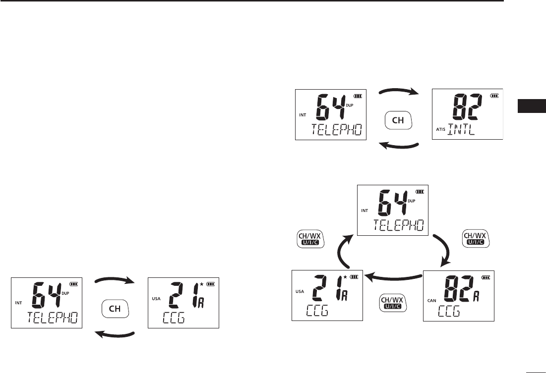
D#HANNEL
Channel 16 is the distress and safety channel. It is used for
establishing initial contact with another station, and for emer-
gency communications. Channel 16 is automatically moni-
tored during both Dualwatch and Tri-watch. While standing
by, you must monitor Channel 16.
q Push ;#= to select Channel 16.
w Push ;#(78s5)#= to return to the condition before
selecting Channel 16, or push [Y]/[Z] to select the
operating channel.
Push
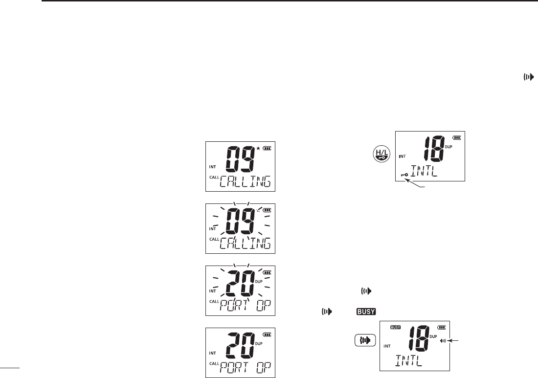
DCall channel
Each regular channel group has separate leisure-use call
channels. The Call channel is monitored during Tri-watch.
The Call channels can be reprogrammed (p. 12) and may be
used to store your most often-used channels in each channel
group for quick recall.
q Hold down ;#= for 1 second to select the Call channel.
sh#!,,vANDTHECALLCHANNELNUMBERAPPEAR
s4HE#ALLCHANNELCANBEREPROGRAMMED3EETHEh#ALLCHANNEL
programming” on page 12 for details.
w Push ;#(78s5)#= to return to the screen before you
selected Call channel, or push [Y]/[Z] to select an
operating channel.
Hold down
for 1 second
9
4
BASIC OPERATION
2
4
5
7
8
9
DU.S.A., International, Canadian and ATIS
channels
The transceiver has U.S.A.*1, International, Canadian*2 and
ATIS*3 channels. You must select the proper channels for the
operating area.
*1Only USA, UK, EXP, CHN and AUS versions.
*2Only USA, EXP and CHN versions.
*3Only HOL version.
Push q;#(78s5)#= to select a regular channel.
s)FTHEWEATHERCHANNELAPPEARSPUSH;#(78s5)#= again.
Push w[Y]/[Z] to select a channel.
sh$50vAPPEARSFORDUPLEXCHANNELS
e To change the channel group, hold down ;#(78s5)#=
for 1 second.
s2EPEATUNTILYOUREACHTHEDESIREDCHANNELGROUP
For U.K. and Australia versions
U.S.A. channelsInternational channels
Hold down
for 1 second
Hold down
for 1 second
Hold down
for 1 second
Hold down
for 1 second
Hold down
for 1 second
For Dutch version
For U.S.A., Export, and China versions
International channels
International channels
U.S.A. channels
ATIS channels
Canadian channels

10
4BASIC OPERATION
DWeather channels
The transceiver has 10 pre-programmed weather channels*.
These are used for monitoring broadcasts from NOAA (Na-
tional Oceanographic and Atmospheric Administration.) The
transceiver can automatically detect a weather alert tone on
the selected weather channel or while scanning.
See the “SET mode items” on page 26 for details.
* For only the USA, EXP, and AUS versions.
Push q;#(78s5)#= to select the weather channel group.
Push w[Y]/[Z] to select a weather channel.
Push e;#(78s5)#= to return to the screen before you
selected the Weather channel group.
11
4
BASIC OPERATION
2
4
5
7
8
9
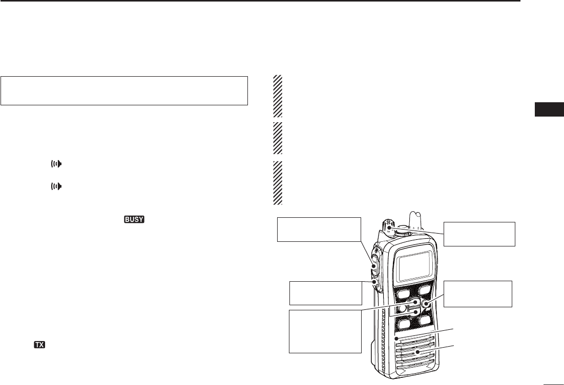
N Receiving and transmitting
CAUTION: Transmitting without an antenna may damage
the transceiver.
Rotate q[VOL] clockwise to turn ON power.
s!NOPENINGCOMMENTSCROLLSACROSSTHEFUNCTIONDISPLAY
s0USH;#= to skip the opening comment.
Set the volume and squelch level. w
± Push [], and push [Z] to open the squelch.
± Rotate [VOL] to set the volume level.
± Push [], and push [Y]/[Z] to set the squelch level.
Push e[Y]/[Z] to select the desired channel.
s0USHING;&!6s(] selects only Favorite channels.
- When receiving a signal, the “ ” icon appears while audio is
heard from the speaker.
- Further adjustment of [VOL] may be necessary at this point.
Push r;(,s,/#+= to select the output power, if necessary.
- “LOW” appears when low power is selected; “MID” appears
when mid power is selected; no indication is displayed when high
power is selected.
- Choose low or mid power to conserve battery power; choose
high power for longer distance communications.
- Some channels are for only low transmission.
t Hold down [PTT] to transmit, and speak at your normal
voice level.
- The appears while transmitting.
- Channel 70 cannot be used for transmission.
Release y[PTT] to receive.
IMPORTANT: To maximize the readability of your transmit-
ted signal, pause a second after pushing [PTT]. Hold the
microphone 5 to 10 cm (2 to 4 inches) from your mouth, and
speak at your normal voice level.
NOTE: The transceiver has a power save function to con-
serve the battery power. The power save function automati-
cally activates when no signal is received for 5 seconds.
To prevent accidental prolonged transmission, the trans-
ceiver has a time-out timer function*. This timer cuts OFF a
transmission after 5 minutes of continuous transmission.
* For only the USA and AUS versions.
q Power ON
w Set the volume
w Set the squelch
level
w Set the squelch
level
e Select the
channel
r Set the output
power
t Push to transmit
y Release to receive
Microphone
Speaker
12
4BASIC OPERATION
12
N Call channel programming
The Call channel key is used to select Channel 9* by default.
However, you can program your most often-used channel in
each channel group for quick recall.
* The channel may differ, depending on the transceiver version.
Hold down q;#(78s5)#= for 1 second several times to
select the desired channel group (USA, INT, CAN, ATIS) to
be programmed.
w Hold down ;#= for 1 second to se-
lect the Call channel.
sh#!,,v AND #ALL CHANNEL NUMBER AP-
pear.
Hold down e;#= again for 3 sec-
onds (until a long beep changes to 2
short beeps) to enter the Call channel
programming mode.
s4HE #ALL CHANNEL NUMBER TO BE PRO-
grammed blinks.
r Push [Y]/[Z] to select the desired
channel.
Push t;#= to program the displayed
channel as the Call channel.
s4HE#ALLCHANNELNUMBERSTOPSBLINKING
N Lock function
This function electronically locks all keys (except for [PTT], [ ]
and ;(,s,/#+=) to prevent accidental channel changes and
function access.
± Push ;(,s,/#+= for 1 second to turn the lock function
ON or OFF.
Hold down
for 1 second
Appears while the loc
k
function is in use.
N Monitor function
The monitor function releases the noise squelch mute to
check the volume level. See page 27 for details of the monitor
switch action.
± Hold down [] for 1 second to activate the monitor func-
tion.
sh ” and “ ” appear and audio is heard.
Appears while the
monitor function is
in use.
Hold down
for 1 second

13
4
BASIC OPERATION
2
4
5
7
8
9
N Adjusting the squelch level
To adjust the transceiver’s squelch level, use the [Y]/[Z]
keys, as described below. In order to properly receive signals,
as well as for the scan to function effectively operate, the
squelch must be adjusted to the proper level.
q Push [], then adjust the squelch level with [Y]/[Z].
- “SQL” and the squelch level are displayed.
- There are 11 squelch levels to choose from: OP is completely
open; 10 is tight squelch; 1 is loose squelch level.
- When no key is pushed for 5 seconds, the transceiver returns to
its normal condition.
w Push [] again to return to normal operating mode.
Push Shows the squelch
level.
Appears during squelch
level adjustment
N AquaQuake water draining function
The AquaQuake water draining function clears water away
from the speaker grill. Without this function, water may muffle
the sound coming from the speaker. The transceiver emits a
vibrating beep when this function is activated.
± While holding down [F], the AquaQuake function is acti-
vated to clear water away from the speaker grill.
s"EEPSOUNDSREGARDLESSOFTHEVOLUMELEVELSETTING
s!CTIVATESFORSECONDSINMAXIMUMTODRAINWATER
s4HETRANSCEIVERNEVERACCEPTSKEYOPERATIONWHILETHE!QUA1UAKE
function is activated.
s4HE !QUA1UAKE FUNCTION CAN NOT BE ACTIVATED WHEN AN OPTIONAL
speaker-microphone is connected.
14
SCAN OPERATION%XCEPTFORTHE$UTCHVERSION
5
N Scan types
Scanning is an efficient way to quickly locate signals over a
wide frequency range. The transceiver has a priority scan set-
ting and normal scan setting.
In addition, the “Weather alert*” and “Auto scan” functions are
also selectable for scanning. These functions can be simul-
taneously activated, depending on the settings in the SET
mode. (pp. 26, 27)
* For only the USA, EXP, and AUS versions.
Set the Favorite channels (scanned channel) before scanning.
Clear those Favorite channels which are not needed or incon-
veniently stop scanning, such as digital communications.
Choose priority or normal scan in the SET mode. (p. 26)
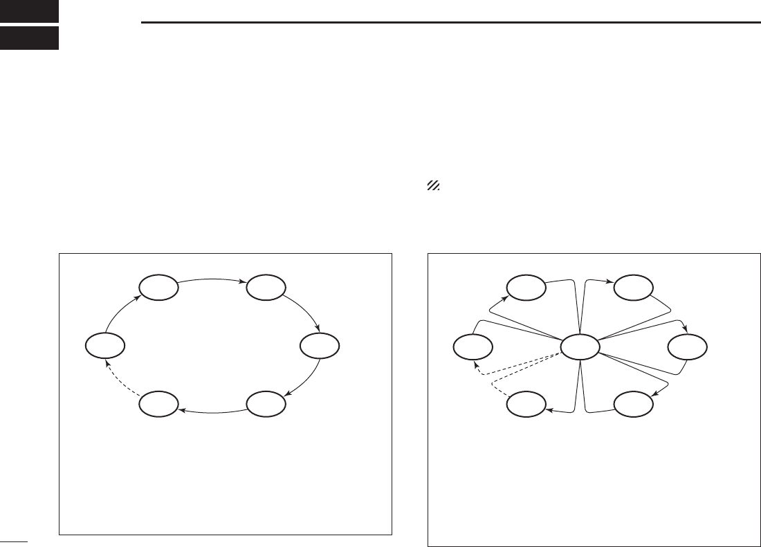
NORMAL SCAN
CH 01 CH 02
WX*
CH 05 CH 04
CH 03
* Previously selected weather channel
when weather alert function is ON.
Normal scan, like priority scan, sequentially searches
through all Favorite channels. However, unlike priority
scan, Channel 16 is not checked unless it is set as a Fa-
vorite channel.
PRIORITY SCAN
WX*
CH 01
CH 16
CH 02
CH 05 CH 04
CH 03
* Previously selected weather channel
when weather alert function is ON
Priority scan sequentially searches through all
Favorite
chan-
nels while monitoring Channel 16. When a signal is detected
on Channel 16, the scan pauses until the signal disappears;
when a signal is detected on a channel other than Channel
16, scan becomes Dualwatch until the signal disappears.
15
5
SCAN OPERATION (Except for the Dutch version)
2
4
5
7
8
9
N Setting Favorite channels
For more efficient scanning, add desired channels as Favorite
channels, or clear the Favorite for unwanted channels.
Untagged channels will be skipped during scanning. Favor-
ite channels can be independently assigned to each channel
group (USA, INT, CAN, ATIS) independently.
Select the desired channel to set as a Favorite channel. q
Hold down w;&!6s(] for 1 second to set the displayed chan-
nel as a Favorite channel.
sh(” appears on the function display.
To cancel the Favorite channel setting, hold down e;&!6s(]
for 1 second.
sh(” disappears.
#LEARINGORSETTING!LL&AVORITE#HANNELSINTHE 3E-
lected Channel Group
While holding down ;&!6s(], turn ON power to clear all the
Favorite channel settings in the channel group.
s2EPEATABOVEPROCEDURETOSETALLCHANNELSAS&AVORITECHANNELS
N Starting a scan
First, set the weather alert function, priority scan function,
scan resume timer and auto scan function, using the SET
mode. (pp. 26, 27)
q Make sure the desired channel group (e.g., USA, CAN, INT,
ATIS) is selected. Move between channel groups by repeat-
edly pushing ;#(78s5)#= for 1 second at a time.
s7HENTHEWEATHERALERTFUNCTIONISINUSESELECTTHEDESIRED
weather channel with ;#(78s5)#= and [Y]/[Z].
* For only the USA, EXP, and AUS versions.
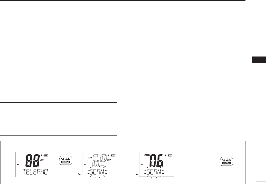
w Push ;3#!.s$5!,= to start a priority or normal scan.
sh3#!.vBLINKSINTHEFUNCTIONDISPLAY
shvAPPEARSONTHECOMMENTINDICATORDURINGAPRIORITYSCAN
s
When a signal is received, the scan pauses until the signal dis-
appears, or resumes after pausing 5 seconds, depending on the
scan resume timer setting. (Channel 16 is still monitored during
a priority scan.)
s0USH [Y]/[Z] to check the scanning of Favorite channels,
change the scanning direction or resume the scan manually.
e To stop the scan, push ;3#!.s$5!,=.
sh3#!.vDISAPPEARS
Scan starts
“SCAN” indication blinks
Push Push
to stop the scan
When receiving a
signal, “SCAN” indica-
tion blinks and audio
is heard.
[Example]: Starting a normal scan.
16
DUALWATCH/TRI-WATCH
6
N Description
Dualwatch monitors Channel 16 while you are receiving
on another channel; Tri-watch* monitors Channel 16 and the
call channel while receiving on another channel.
*For the Dutch transceiver version
Only Dualwatch can be used.
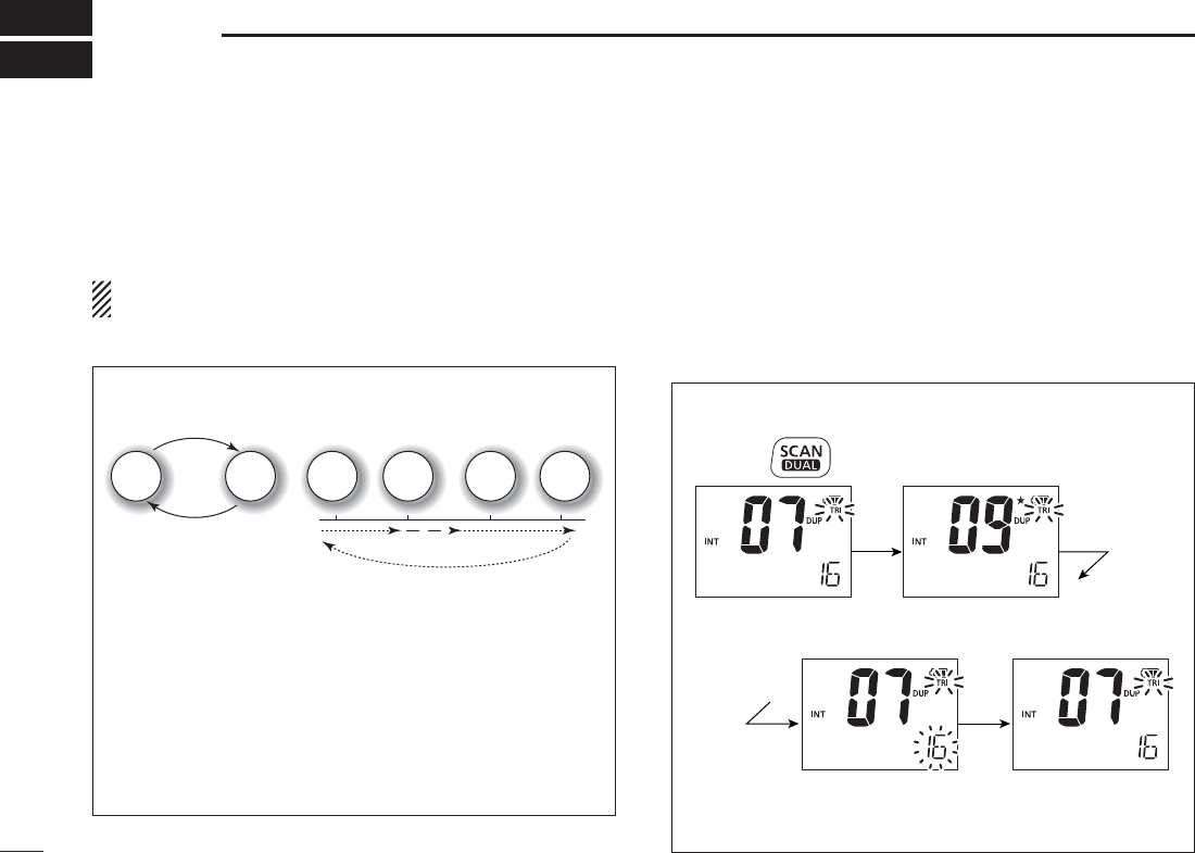
N Operation
q Select a desired operating channel.
w Hold down ;3#!.s$5!,= for 1 second to start Dualwatch
or Tri-watch (depending on the SET mode setting; p. 27).
sh$5!,vBLINKSDURING$UALWATCHh42)vBLINKSDURING4RIWATCH
s!BEEPTONESOUNDSWHENASIGNALISRECEIVEDON#HANNEL
s4RIWATCHBECOMES$UALWATCHWHENRECEIVINGASIGNALONTHE
Call channel.
e
To cancel Dualwatch/Tri-watch, push ;3#!.s$5!,= again.
DUALWATCH/TRI-WATCH SIMULATION
Dualwatch Tri-watch
Call
channel
Ch 88
Ch 16 Ch 88 Ch 16 Ch 88 Ch 9
s)FASIGNALISRECEIVEDON#HANNEL$UALWATCH4RIWATCH
pauses on Channel 16 until the signal disappears.
s)FASIGNALIS RECEIVEDON THE #ALLCHANNELDURING4RI
watch, Tri-watch becomes Dualwatch until the signal dis-
appears.
s4OTRANSMITONTHESELECTEDCHANNELDURING$UALWATCH
Tri-watch, hold down [PTT].
[Example]: Operating tri-watch on INT channel 07.
A signal is received
on the Call channel.
A signal received on
Channel 16 always
takes priority.
Tri-watch resumes
after the signal
disappears.
Tri-watch starts.
Hold down for 1 second
17
7
FUNCTION MODE OPERATION
2
4
5
7
8
9
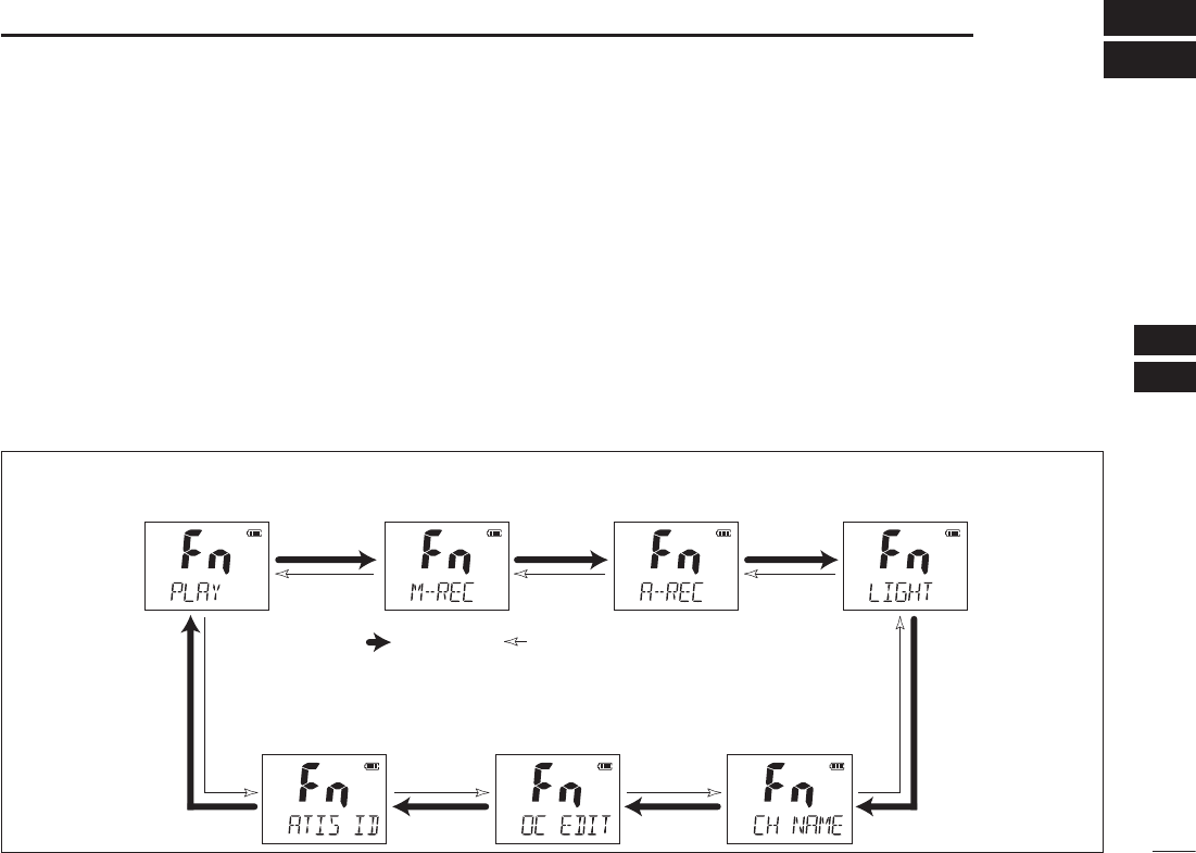
N About the function mode
There are 7 transceiver functions‡ in the function mode: Play
back function‡, Manual recording function‡, Automatic record-
ing function‡, backlight function, channel naming function,
opening comment entry function and the ATIS code program-
ming function†.
†For only the Dutch and German versions.
‡Depending on versions.
D Entering the function mode
Push q[F] to enter the function mode.
sh0,!9v0LAYBACKFUNCTIONAPPEARS
s7HENNOKEYISPUSHEDFORSECONDSTHETRANSCEIVERRETURNSTO
its normal condition.
w Push [Y]/[Z] to select the desired item.
e Push ;(,s,/#+= to select or decide the desired option
of the item.
s3OMEITEMSEXITTHEFUNCTIONMODEWHENPUSHING;(,s,/#+=.
To exit the function mode, push r[F].
D FUNCTION MODE ITEMS
Playback function*,‡
Manual recording
function‡
Automatic recording
fucntion‡Backlight function
ATIS code programming
function†
Opening comment
entry function
Channel naming
function
: Push [Y] : Push [Z] *Starting item
†For only the Dutch and German versions.
‡Depending on versions.
18
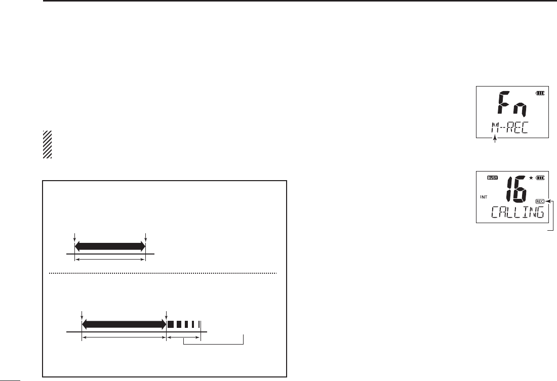
7FUNCTION MODE OPERATION
You can record the received signal whenever you want by us-
ing the manual recording function.
This function can record the received signal for maximum 30
seconds.
The transmitted signal cannot be recorded.
The previously recorded signal will be overwritten when you re-
cord the next audio using this function.
q Push [F] to enter the function mode,
and then push [Y]/[Z] to select the
manual recording function.
sh-2%#vAPPEARS
w Push ;(,s,/#+= to start record-
ing.
sh2%#vAPPEARS
s7HEN THE SIGNAL DISAPPEARS THE
transceiver continues recording
without audio.
Push e[F] to stop the recording.
s4HERECORDINGWILLAUTOMATICALLYSTOP
after 30 seconds.
Manual recording
mode appears.
“REC” appears
while recording.
Example: 20 seconds
30 seconds
When receiving a signal for 30
seconds or less, this function
records all contents.
30 seconds after you start the manual recording, the
recording will automatically stop.
These contents
will not be recorded.
Start manual
recording.
Start manual
recording.
Stop manual
recording.
Automatically stops
recording.
N -ANUALRECORDINGFUNCTION$EPENDINGONVERSIONS
19
7
FUNCTION MODE OPERATION
2
4
5
7
8
9
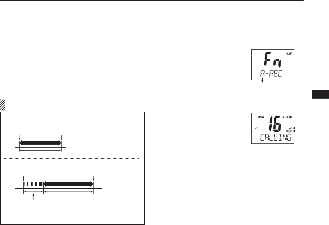
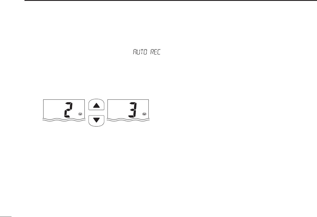
When this function is turned ON, the transceiver automati-
cally records the received signal into the memory.
The maximum recording time is 60 seconds.
s4HETRANSMITSIGNALCANNOTBERECORDED
s)FASIGNALLESSTHANSECONDSISRECORDEDTHENEXTRECORDEDSIG-
nal is added into the same data.
s4HERECORDINGTHRESHOLDLEVELCANBESETINTHESETMODE3EEPAGE
30 for details.
NOTE: Even if you turn OFF the transceiver, this function remains
ON.
Push q[F] to enter the function
mode, and then push [Y]/[Z] to
select the automatic recording
function.
sh!2%#vAPPEARS
w Push ;(,s,/#+= to turn the
function ON or OFF.
s4HE AUTOMATIC RECORDING ICON AP-
pears when the function is turned
ON.
s!FTERPUSHING;(,s,/#+=, exits the
function mode.
e When a signal is received, the
transceiver automatically starts
recording.
sh2%#vAPPEARSWHILERECORDING
s4HERECORDINGWILLAUTOMATICALLYSTOP
when the received signal disap-
pears, or the received signal strength becomes weaker than the
set threshold level in the set mode
(p. 30).
Automatic recording
mode appears.
“REC” is appeared
while recording.
Automatic recording
icon appears.
Example: 40 seconds
60 seconds
When receiving a signal for 60
seconds or less, this function
records all contents.
After 60 seconds has passed from
starting the automatic recording,
this function records the 60 seconds
before stopping to record.
These contents
won’t be recorded.
Starts recording
Starts recording
Stops recording
Stops recording
N !UTOMATICRECORDINGFUNCTION$EPENDINGONVERSIONS
20
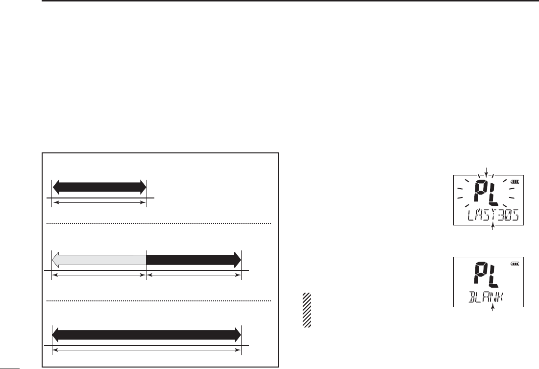
7FUNCTION MODE OPERATION
This transceiver has two voice recorders.
One is the manual recording function which can record for 30
seconds. The other is the automatic recording function which
can record the last 60 seconds of the receiving signal.
There are three play-back modes as follows.
Push q[F] to enter the function mode.
sh0,!9vAPPEARS
Push w;(,s,/#+=to enter the play back selection mode,
and then push [Y]/[Z] to select the desired play back
mode from “M-PLAY,” “LAST30S,” or “LAST60S.”
If there is no recorded signal in the transceiver, “BLANK”
appears.
s-0,!9 0LAY BACK THE MANUALLY
recorded signal.
s,!3430LAY BACK THE LAST
seconds of the automati-
caliy recorded signal.
s,!3430LAY BACK THE AUTOMATI-
caliy recorded signal for
60 seconds.
Push e;(,s,/#+= to play back
the recorded signal.
sh0,vBLINKS
s4O STOP THE PLAY BACK PUSH
;(,s,/#+= again.
DO NOT detach the battery pack while
the transceiver is turned ON. Other-
wise, the data could be lost or delet-
ed.
Deleting a recorded signal:
While selecting the desired data to delete, hold down ;&!6s(]
for 3 seconds until 2 short beeps sound.
Blinks while playbacking.
Playback mode appears.
“BLANK” appears when
the transceiver has no
recorded signal.
ding
ding
ding
Playing back for 30 seconds (maximum).
Select “M-PLAY”
Select “LAST60S”
Select “LAST30S”
Not playing back.
Playing back for 60 seconds (maximum).
Playing back for
30 seconds (maximum).
N 0LAYBACKFUNCTION$EPENDINGONVERSIONS
21
7
FUNCTION MODE OPERATION
2
4
5
7
8
9
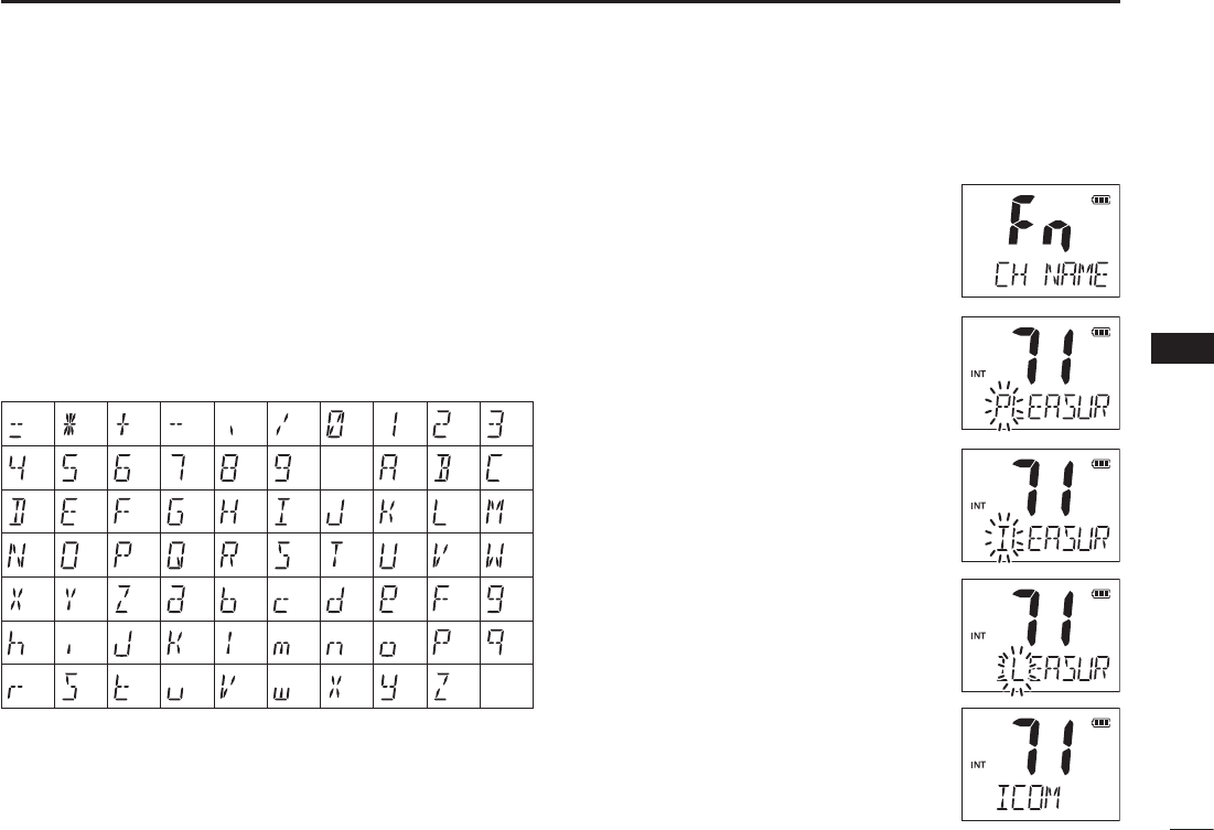
N Channel naming function
The IC-M73/IC-M73EURO can assign up to 10-character
channel names for each operating channel, including each
weather channel. This provides easy recognition of the chan-
nel in use, or station names.
When shipped from the factory, the IC-M73/IC-M73EURO is
programmed with default names for each VHF marine chan-
nel. These defaults can be changed, if desired.
DUsable characters
DChannel name programming
Push q[Y]/[Z] to select a channel to
program.
s(OLDDOWN;#(78s5)#= for 1 second
to select a channel group, if necessary.
Push w[F] to enter the function mode,
and then push [Y]/[Z] to select the
channel naming function.
sh#(.!-%vAPPEARS
e Push ;(,s,/#+=to edit the channel
name.
s4HE ST CHARACTER OF THE CURRENTLY PRO-
grammed name blinks.
Push r[Y]/[Z] to select a character.
Push t;#(78s5)#= to move to the
right; then push [Y]/[Z] to select a
character.
s0USH;3#!.s$5!,= to move to the left.
Continue until the desired charac- y
ters have been selected, then push
;(,s,/#+= to return to normal op-
eration.
Deleting a channel name (All clear):
While selecting the desired channeI
name in the channel name editing mode,
push ;&!6s(] to delete the selected
channel name.
(=)
(4)
(D)
(N)
(X)
(h)
(r)
()
(5)
(E)
(O)
(Y)
(i)
(s)
(+)
(6)
(F)
(P)
(Z)
(j)
(t)
(7)
(G)
(Q)
(a)
(k)
(u)
(,)
(8)
(H)
(R)
(b)
(l)
(v)
(/)
(9)
(I)
(S)
(c)
(m)
(w)
(0)
(Space)
(J)
(T)
(d)
(n)
(x)
(1)
(A)
(K)
(U)
(e)
(o)
(y)
(2)
(B)
(L)
(V)
(f)
(p)
(z)
(3)
(C)
(M)
(W)
(g)
(q)
(–)
22
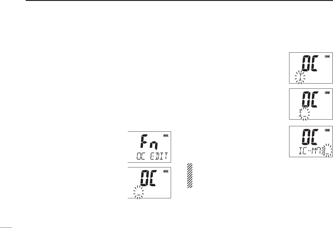
7FUNCTION MODE OPERATION
The IC-M73/IC-M73EURO can assign up to 16-character
opening comments.
You may replace the factory-set opening comment with a
comment of your own. The opening comment appears each
time the IC-M73/IC-M73EURO is powered ON. The comment
may be up to 16 characters long.
You can use same characters as “Channel naming function.”
(p. 21)
DOpening comment programming
Push q[F] to enter the function mode, and then push [Y]/
[Z] to select the channel naming
function.
sh/#%$)4vAPPEARS
w Push ;(,s,/#+= to edit the open-
ing comment.
s4HE ST CHARACTER OF THE CURRENTLY PRO-
grammed comment blinks.
Push e[Y]/[Z] to select a character.
r Push ;#(78s5)#= to move to the
right; then push [Y]/[Z] to select a
character.
s0USHING;3#!.s$5!,=, moves to left.
Continue until the desired charac- i
ters have been entered, then push
;(,s,/#+= to return to normal op-
eration.
Deleting the opening comment (All
clear):
While in the opening comment editing
mode, push ;&!6s(] to delete.
The programmed opening comment is briefly displayed or
scrolled when the transceiver is powered ON.
However, the opening comment display can be skipped by
pushing ;#=.
N Opening comment entry function
23
7
FUNCTION MODE OPERATION
2
4
5
7
8
9
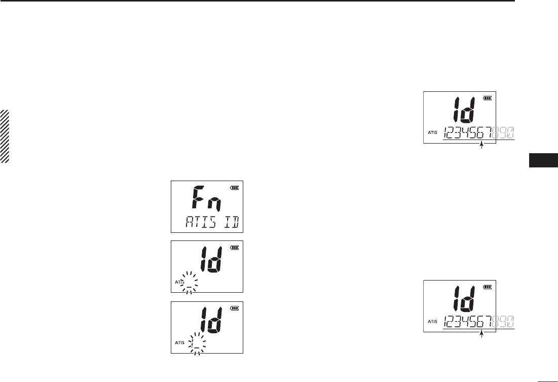
The 10-digit ATIS code can be programmed and confirmed
with the following operation.
The ATIS code programming is not necessary and con-
firmation can only be performed when the ATIS code has
been programmed by your dealer. The code programming
can be performed 1 time only, if the code has not been
programmed by your dealer.
Push q[F] to enter the function mode,
and then push [Y]/[Z] to select the
ATIS code programming function.
sh!4)3)$vAPPEARS
w Push ;(,s,/#+= to edit the ATIS
code.
sh)DvANDh!4)3vAPPEARANDTHESTCHAR-
acter of the code blinks.
Push e[Y]/[Z] to select a number.
r Push ;#(78s5)#= to move to the
right; then push [Y]/[Z] to select a
number.
s0USH ;3#!.s$5!,= to move to the
left.
After inputting the 10-digit ATIS t
code, push ;(,s,/#+= to write
the code into the memory, then
goes to the ATIS code confirma-
tion mode.
Deleting the ATIS code (All clear):
While in the ATIS code editing mode, push ;&!6s(] to de-
lete.
DATIS code confirmation
7HENTHE!4)3CODEHASBEENPROGRAMMED
Push q[F] to enter the function mode, and then push [Y]/
[Z] to select the ATIS code programming function.
sh!4)3)$vAPPEARS
w Push ;(,s,/#+=to confirm the
ATIS code.
sh)DvANDh!4)3vAPPEAR
s4HE !4)3 CODE IS DISPLAYED AND
scrolls in the channel comment dis-
play.
e Push ;(,s,/#+= to return to
normal operation.
.
Scrolls
N ATIS code programming
&ORONLYTHE$UTCHAND'ERMANVERSIONS
Scrolls

24
7FUNCTION MODE OPERATION
N Backlight function
This function is convenient for nighttime operation. The back-
lighting can also be turned OFF in the SET mode. (p. 27)
±
Push any key other than [PTT] to turn ON the backlighting.
s4HEBACKLIGHTINGISAUTOMATICALLYTURNED/&&AFTERSECONDSOF
inactivity.
Push q[F] to enter the function mode,
and then push [Y]/[Z] to select the
backlighting function.
sh,)'(4vAPPEARS
w Push ;(,s,/#+= to turn the func-
tion ON or OFF.
s!FTER PUSHING ;(,s,/#+=, exits from
the function mode.
Backlight mode
appears.
25
8
SET MODE
2
4
5
7
8
9
N SET mode programming
The SET mode is used to change the status of 17 transceiver
functions†: Beep tone function, Weather alert function†, Prior-
ity scan, Scan resume timer, Auto scan start function, Dual/
Tri-watch function, Monitor key action, Display backlight, LCD
contrast selection, Power save function, Scroll type selection,
Scroll speed selection, RX noise cancel function†, TX noise
cancel function†, RX bass boost function†, TX bass boost
function† and the Automatic recording threshold level selec-
tion†.
DSET mode operation
Turn OFF power. q
w While holding down [], turn ON power to enter the SET
mode.
s4HEh"%%0v"EEPTONEFUNCTIONSETTINGAPPEARS
e Push [], or push [ ] and [Y]/[Z] to select the desired
item.
Push r[Y]/[Z] to select the desired option of the item.
To exit the SET mode, push t;#=.
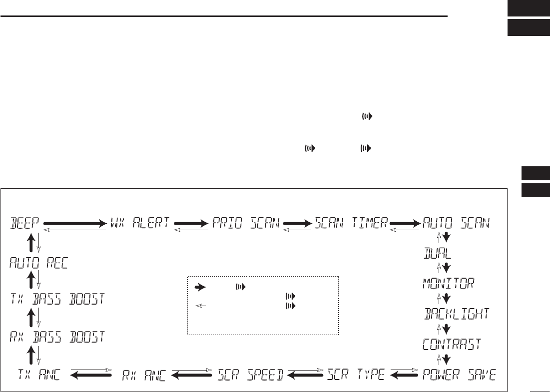
DSET MODE ITEMS
Beep tone function* Weather alert function†Priority scan†Scan resume timer†
Auto scan start function
†
Dual/Tri-watch
function†
Monitor key
action
Display
backlight
LCD contrast
selection
Automtic recording
threshold level selection†
TX bass
boost function†
RX bass
boost function†
Power save function
Scroll type selectionScroll speed selectionRX noise cancel function†
TX noise cancel function
†
: Push [ ], or
while holding down [ ], push [Y]
: While holding down [ ], push [Z]
*Starting item
†Depending on versions
26
8SET MODE
N SET mode items
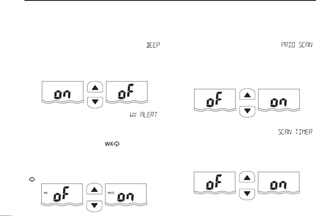
DBeep tone function “ ”
Turns ON the key touch beep sound or AJ, or turns OFF the
sound OFF.
s/. !lXEDBEEPSOUNDSDEFAULT
s!* 4HEPRESETBEEPSEXAMPLEDOREMISOUND
s/&&3ILENTOPERATION
Push
Beep tone ON (default) Beep tone OFF
Weather alert function “ D”
For only the USA, EXP, and AUS versions, a NOAA broadcast
station transmits a weather alert tone before any important
weather announcements. When the weather alert function is
turned ON, any detected weather alert will make the IC-M73/
IC-M73EURO activate a blinking “ ” alert icon on the
function display and repeatedly sound a beep tone. The blink-
ing and beeping stops when the radio is picked up and op-
erated. The previously selected weather channel is checked
any time during standby, or while scanning, when the power
save function is activated.
sh ” appears when the function is turned ON.
Push
Weather alert function
OFF
(
default
)
Weather alert functio
n
ON
DPriority scan function “ ”
Except for the HOL version, the transceiver has 2 scan
types— normal (OFF) and priority (ON) scans. Normal scan
searches all Favorite (TAG) channels in the selected channel
group. Priority scan sequentially searches all Favorite (TAG)
channels while monitoring Channel 16.
s4HEDEFAULTSETTINGMAYDIFFERDEPENDINGONTHEVERSION
Push
Normal scan (default) Priority scan
DScan resume timer “ ”
Except for the HOL version, the scan resume timer can be set
as a pause (OFF) or timer scan (ON). When OFF is selected,
the scan pauses until a received signal disappears. When ON
is selected, the scan pauses for 5 seconds after receiving a
signal and then resumes even if a signal has been received.
Push
Scan resume timer
OFF (default)
Scan resume timer
ON
27
8
SET MODE
2
4
5
7
8
9
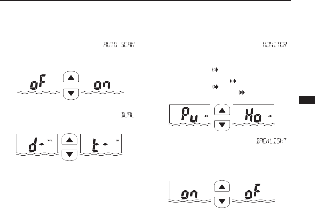
DAuto scan function “ ”
Except for the HOL version, the auto scan function automati-
cally starts the desired scan when no signal is received, and
no operation is performed for 30 seconds
Push
Auto scan OFF (default) Auto scan ON
DDual/Tri-watch function “ ”
Except for the HOL version, this item selects Dual or Tri-watch
as desired. See page 16 for details.
Push
Dualwatch (default) Tri-watch
DMonitor key action “ ”
The monitor key action temporarily cuts off the squelch func-
tion. This key action contains PUSH (Pu) or HOLD (Ho) set-
tings, as shown below.
s0U053(!FTER PUSHING [] for 1 second, the squelch opens
and audio is heard. The squelch is held open while con-
tinuously holding down [ ]. (default)
s(O(/,$!FTER PUSHING [ ] for 1 second, the squelch opens
and audio is heard even if [ ] is released. To close
the squelch, push any key.
Push
Push setting (default) Hold setting
Backlight function “ D”
This function is convenient for nighttime operation. The back-
light can be turned ON or OFF.
s4HE BACKLIGHT IS AUTOMATICALLY ACTIVATED WHEN ANY KEY EXCEPT FOR
[PTT] is pushed.
s4HEBACKLIGHTISAUTOMATICALLYTURNED/&&AFTERSECONDSOFINAC-
tivity.
Push
Backlight ON
(default)
Backlight OFF
28
8SET MODE
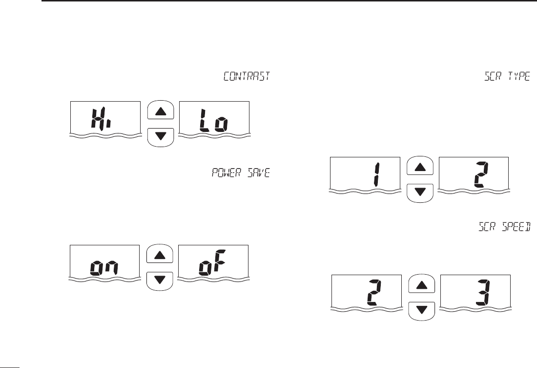
DLCD contrast selection “ ”
The contrast of the LCD can be set to Hi (default) or Lo.
Push
High contrast (default) Low contrast
DAuto power save function “ ”
The auto power save function reduces current drain by deac-
tivating the receiver circuit for preset intervals.
s/. 4HEPOWERSAVEFUNCTIONISTURNED/.4HEPOWERSAVEFUNC-
tion will activate when no signal is received, and no operation
is performed for 5 seconds
s/&&4HEPOWERSAVEFUNCTIONISTURNED/&&
Push
Power save ON
(default)
Power save OFF
DChannel name scroll type “ ”
Set the channel name/comment scroll type to 1 or 2.
s4HElRSTCHARACTERSAREDISPLAYEDFORAPPROXIMATELYSECOND
then scrolls. When the channel name or comment is 7 character
or less, it does not scroll (default).
s4HECHANNELNAMEORCOMMENTSCROLLSREGARDLESSOFTHENUMBER
of characters after no name or comment (blank) is displayed for
1 second.
Push
Scroll type 1 (default) Scroll type 2
Scrolling speed “ D”
Selects the channel name/comment scroll speed.
s3CROLLSCHARACTERSINASECOND
s3CROLLSCHARACTERSINASECOND
s3CROLLSCHARACTERSINASECOND
Push
Scroll speed 2 (default) Scroll speed 3
29
8
SET MODE
2
4
5
7
8
9
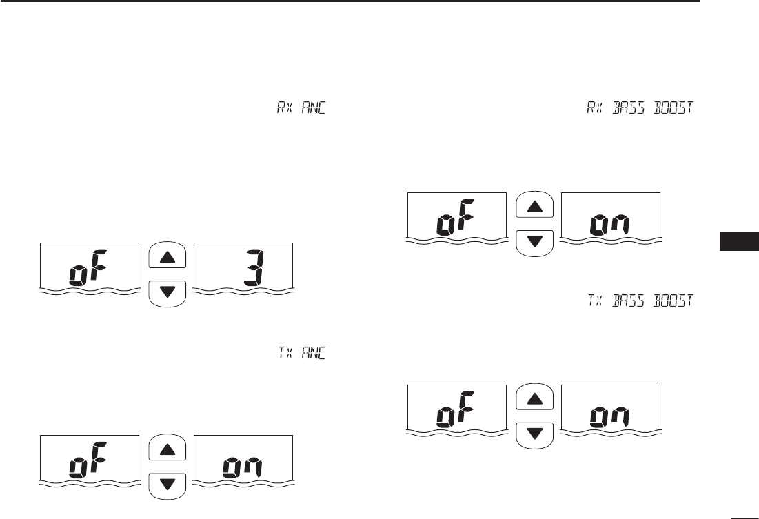
DRX Noise Cancel function “ ”
Set the Noise Cancel function for reception. The function may not be
available, depending on the transceiver version.
s/&&4URNS/&&THEFUNCTION
s 4HE.OISE#ANCELFUNCTIONREDUCESRANDOMNOISECOMPONENTS
in the received signal to approximately one half.
s 4HE.OISE#ANCELFUNCTIONREDUCESRANDOMNOISECOMPONENTS
in the received signal to approximately one third.
s 4HE.OISE#ANCELFUNCTIONREDUCESRANDOMNOISECOMPONENTS
in the received signal to approximately one tenth.
Push
RX noise cancel
OFF (default)
RX noise cancel 3
DTX Noise Cancel function “ ”
Set the Noise Cancel function for transmission. The function may not
be available, depending on the transceiver version.
s/&&4URNS/&&THEFUNCTION
s/. 4HE .OISE #ANCEL FUNCTION REDUCES RANDOM NOISE COMPO-
nents in the transmitted signal to one third.
Push
TX noise cancel
OFF (default)
TX noise cancel ON
DRX bass boost function “ ”
Set the bass boost function for reception.The function may not
be available, depending on the transceiver version.
s/&&4URNS/&&THEFUNCTION
s/. 4HE28BASSBOOSTFUNCTIONBOOSTSTHEBASSLEVELOFTHERE-
ceive audio tone.
Push
RX bass boost
OFF (default)
RX bass boost ON
DTX bass boost function “ ”
Set the bass boost function for transmission. The function may
not be available, depending on the transceiver version.
s/&&4URNS/&&THEFUNCTION
s/. 4HE48BASSBOOSTFUNCTIONBOOSTSTHEBASSLEVELOFTHETRANS-
mit audio tone.
Push
TX bass boost
OFF (default)
TX bass boost ON
30
8SET MODE
DAutomatic recording threshold level
“ ”
Set the automatic recording threshold level. The function may
not be available, depending on the transceiver version.
s
Set the threshold level to shallow. Weak signals will automatically be
recorded into memory.
s
Set the threshold level to mid.
s
Set the threshold level to deep. Weak signals will not automatically
be recorded into memory.
Push
Automatic recording
threshold level 2 (default)
Automatic recording
threshold level 3

31
9
BATTERY CHARGING
2
4
5
7
8
9
N Battery cautions
Misuse of Lithium-ion batteries may result in the following
hazards: smoke, fire, or battery rupture.
Misuse can also cause other battery damage or degrada-
tion of battery performance.
sR DANGER! Use and charge only specified Icom battery
pack with Icom transceiver. Only Icom battery pack is tested
and approved for use with Icom transceiver. Using third-
party or counterfeit battery packs may cause smoke, fire, or
cause the battery to burst.
D Battery caution
sR DANGER! DO NOT hammer or otherwise impact the bat-
tery. Do not use the battery if it has been severely impacted
or dropped, or if the battery has been subjected to heavy
pressure. Battery damage may not be visible on the outside
of the case. Even if the surface of the battery does not show
cracks or any other damage, the cells inside the battery may
rupture or catch fire.
sR DANGER! NEVER use or leave battery pack in areas
with temperatures above +60˚C (+140˚F). High tempera-
ture buildup in the battery, such as could occur near fires
or stoves, inside a sun-heated car, or by setting the battery
in direct sunlight may cause the battery to rupture or catch
fire. Excessive temperatures may also degrade battery per-
formance or shorten battery life.
sR DANGER! DO NOT expose the battery to rain, snow,
seawater, or any other liquids. Do not charge or use a wet
battery. If the battery gets wet, be sure to wipe it dry before
using. The battery by itself is not waterproof.
sR DANGER! NEVER incinerate a used battery pack since
internal battery gas may cause a rupture or explosion.
sR DANGER! NEVER solder the battery terminals, or NEV-
ER modify the battery pack. This may cause heat genera-
tion, and the battery may rupture, emit smoke or catch fire.
sR DANGER! Use the battery only with the transceiver for
which it is specified. Never use a battery with any other
equipment, or for any purpose that is not specified in this
instruction manual.
sR DANGER! If fluid from inside the battery gets in your
eyes, blindness can result. Rinse your eyes with clean wa-
ter, without rubbing them, and see a doctor immediately.
sR WARNING! Immediately stop using the battery if it emits
an abnormal odor, heats up, or is discolored or deformed. If
any of these conditions occur, contact your Icom dealer or
distributor.
sR WARNING! Immediately wash, using clean water, any
part of the body that comes into contact with fluid from in-
side the battery.

32
9BATTERY CHARGING
sR WARNING! NEVER put the battery in a microwave oven,
high-pressure container, or in an induction heating cooker.
This could cause overheating, a fire, or cause the battery
to rupture.
sCAUTION: Always use the battery within the specified tem-
perature range for the transceiver* and the battery itself
(–20˚C to +60˚C; –4˚F to +140˚F).
* EXP/USA : –20˚C to +60˚C; –4˚F to +140˚F
CHN/EUR/FRG/HOL/UK : –15˚C to +55˚C; +5˚F to +131˚F
AUS : –10˚C to +55˚C; +14˚F to +131˚F
Using the battery out of its specified temperature range will
reduce the battery’s performance and battery life. Please
note that the specified temperature range of the battery may
exceed that of the transceiver. In such cases, the transceiv-
er may not work properly because it is out of its operating
temperature range.
sCAUTION: Shorter battery life could occur if the battery is
left fully charged, completely discharged, or in an excessive
temperature environment (above +50˚C; +122˚F) for an ex-
tended period of time. If the battery must be left unused for a
long time, it must be detached from the radio after discharg-
ing. You may use the battery until the remaining capacity is
about half, then keep it safely in a cool dry place with the
temperature range as below;
–20˚C to +50˚C (–4˚F to +122˚F) (within a month)
–20˚C to +35˚C (–4˚F to +95˚F) (within three months)
–20˚C to +20˚C (–4˚F to +68˚F) (within a year)
DCharging caution
sR DANGER! NEVER charge the battery pack in areas with
extremely high temperatures, such as near fires or stoves,
inside a sun-heated car, or in direct sunlight. In such en-
vironments, the safety/protection circuit in the battery will
activate, causing the battery to stop charging.
sR WARNING! DO NOT charge or leave the battery in the
battery charger beyond the specified time for charging. If
the battery is not completely charged by the specified time,
stop charging and remove the battery from the battery char-
ger. Continuing to charge the battery beyond the specified
time limit may cause a fire, overheating, or the battery may
rupture.
sR WARNING! NEVER insert the battery and transceiver
(battery attached to the transceiver) into the charger if it is
wet or soiled. This could corrode the battery charger termi-
nals or damage the charger. The charger is not waterproof.
sCAUTION: DO NOT charge the battery outside of the speci-
fied temperature range: +10˚C to +40˚C (+50˚F to +104˚F).
Icom recommends charging the battery at +20˚C (+68˚F).
The battery may heat up or rupture if charged out of the
specified temperature range. Additionally, battery perfor-
mance or battery life may be reduced.
33
9
BATTERY CHARGING
2
4
5
7
8
9
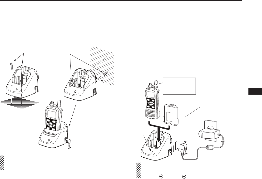
N Supplied battery charger
D"#INSTALLATION
q
w
e
Supplied screws
Supplied screws
To
To
Use a rubber band t
o
secure the transceive
r
if desired.
R DANGER! Charge the BP-245H with only the specified
chargers listed on page 43. Otherwise, it may cause smoke, fire,
or cause the battery to burst.
DCharging
Connect the AC adapter as shown below. q
Insert the battery pack with or without the transceiver into w
the charger.
s4HECHARGEINDICATORLIGHTSORANGE
e Charge the battery pack approximately 3 hours, depend-
ing on the remaining power level.
s4HECHARGEINDICATORLIGHTSGREENWHENCHARGINGISCOMPLETE
Transceiver
Battery pack
AC adapter
Charger
indicator
OPC-515L* (for a
13.8 V power
source) or the
CP-25H (for a 12 V
cigarette lighter
socket) can be used
instead of the AC
adapter.
CAUTION: NEVER connect the OPC-515L to a power
source using reverse polarity. This will ruin the battery
charger.
White line: Black line :
*
Turn OFF the
transceiver power
while charging.
34
9BATTERY CHARGING
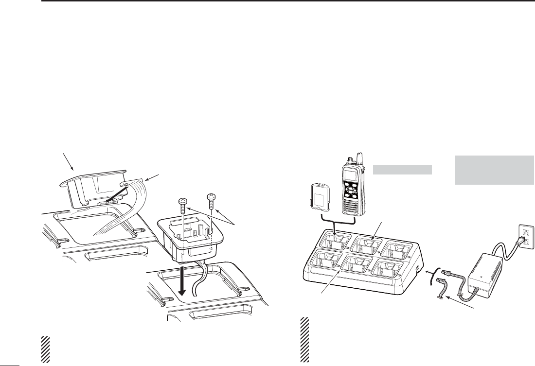
N Optional battery chargers
D!$INSTALLATION
Connect the 8-pin connector of the each charger slot to q
the AD-129 desktop charger adapter’s plug.
Install the adapter into the each charger slot in the direc- w
tion of the arrow, then use the two supplied screws to se-
cure the adapter to the charger.
D2APIDCHARGINGWITHTHE"#"#3OR
/0#
The optional BC-197 with the BC-157S will simultaneously
charge up to 6 Li-ion battery packs. The following items are
additionally required. (Charging time: approximately 3 hours)
s3IX!$CHARGERADAPTERS
s!N!#ADAPTER"#3ORTHE$#POWERCABLE/0#
Desktop charger adapter
8-pin connector
Supplied
screws
Battery
pack
The charger adapters
are installed in each slot.
Transceiver
Turn OFF power
(An AC adapter is
not supplied with
some versions.)
AC adapter
(Connect to a DC power supply: 12 to 16 V/at least 7 A)
Status indicator
(each indicator independently functions)
DC power cable (OPC-656)
OPC-656*
DC power cable
*
NEVER reverse the polarity when connecting the power cable to
a power source. This will ruin the battery charger.
Red line : + Black line : _
NEVER transmit near
the BC-197 or the AC
adapter while charging.
R DANGER! Charge the BP-245H with only the specified
chargers listed on page 43. Otherwise, it may cause smoke, fire,
or cause the battery to burst.
35
10
OPTIONAL SWIVEL BELT CLIP
2
4
5
7
8
9
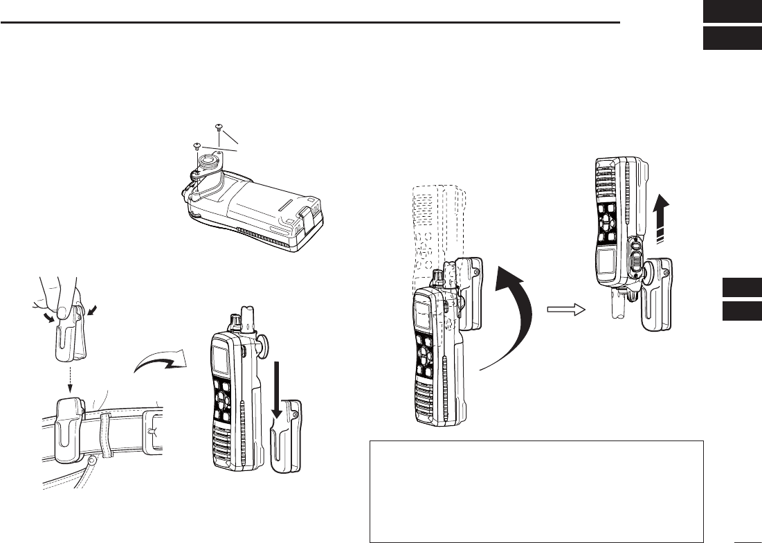
N Attaching
Screw the base clip to the q
back of the transceiver us-
ing the two screws (sup-
plied), as shown to the right.
Clip the belt clip over your belt and insert the transceiver. w
Once the transceiver is locked in place, it swivels. e
N Detaching
± Turn the transceiver upside down in the direction of the
arrow and pull out from the belt clip.
R CAUTION: HOLD THE TRANSCEIVER TIGHTLY WHEN
HANGING OR DETACHING THE TRANSCEIVER FROM
THE BELT CLIP.
Otherwise the transceiver may not be attached to the belt
clip or swivelled properly if the transceiver is accidentally
dropped and the base clip is scratched or damaged.
Supplied screws
36
OPTIONAL SPEAKER-MICROPHONE
11
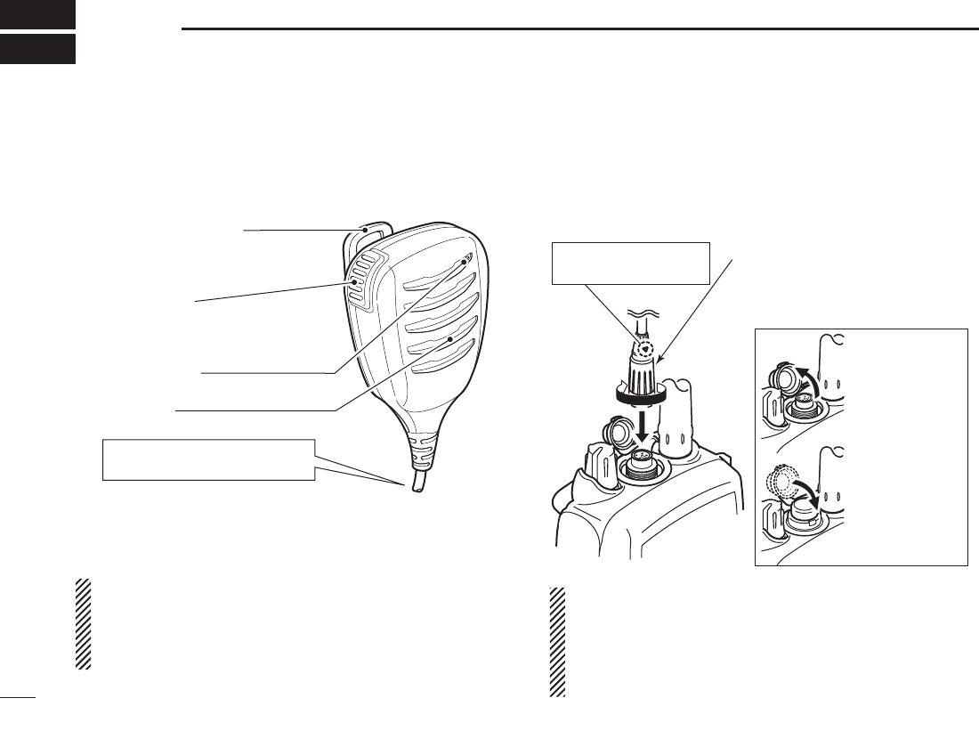
N (-DESCRIPTIONS
HM-202 is also an optional speaker microphone. see the
page 43 for details.
NEVER immerse the connector in water. If the connector
becomes wet, be sure to dry it BEFORE attaching it to the
transceiver.
NOTE: The microphone is located at the top of the speak-
er-microphone, as shown in the diagram above. To maxi-
mize the readability of your transmitted signal (voice), hold
the microphone approximately 5 to 10 cm (2 to 4 inches)
from your mouth, and speak in a normal voice level.
N Attaching
Insert the speaker-mic connector onto the [SP MIC] connec-
tor and carefully screw it tight, as shown in the diagram below.
Be careful not to cross-thread the connection.
Set the triangle mark
to the front side.
CAUTION: Attach the speaker-
microphone’s connector securely
to prevent accidental dropping, or
water intrusion in the connector.
Detaching:
Pull up the cap
in the direction
of the arrow to
detach it.
Attaching:
Attach the cap
in the direction
of the arrow
completely.
IMPORTANT: KEEP the transceiver’s [SP MIC] connector
cap attached when the speaker-microphone is not in use.
Water will not get into the transceiver even if the cover is
not attached; however, the terminals (pins) will become
rusty, or the transceiver will function abnormally if the con-
nector has become wet.
PTT switch
Push to transmit.
Release to receive.
Microphone
Speaker
Alligator type clip
To attach the speaker-microphone
to your shirt or collar.
Turn OFF the transceiver power
when connecting the HM-167.

37
12
TROUBLESHOOTING
2
4
5
7
8
9
PROBLEM POSSIBLE CAUSE SOLUTION REF.
The transceiver does not
turn ON.
s4HEBATTERYISDEPLETED
s"ADCONNECTIONTOTHEBATTERYPACK
s2ECHARGETHEBATTERYPACK
s#HECKTHECONNECTIONTOTHETRANSCEIVER
pp. 33,
34
p. 3
No sound from the speak-
er.
s3QUELCHLEVELISTOOTIGHT
s6OLUMELEVELISTOOLOW
s3PEAKERHASBEENEXPOSEDTOWATER
s7ATERHASENTEREDTO[SP MIC] connector.
s3ETSQUELCHTOTHETHRESHOLDPOINT
s2OTATE[VOL] to set a suitable level.
s(OLDDOWN[F] to drain water from the speaker.
s$RY[SP MIC] connector.
p. 13
p. 11
p. 13
—
Transmitting is impossible,
or high power can not be
selected.
s3OMECHANNELSAREFORLOWPOWERORRECEIVE
only.
s4HEBATTERYISEXHAUSTED
s4HEBATTERYISOVERCHARGED
s4HEOUTPUTPOWERISSETTOLOW
s4HETRANSCEIVERISOVERHEATED
s#HANGECHANNELS
s2ECHARGETHEBATTERYPACK
s6ERIFYTHEBATTERYVOLTAGEISCORRECT
s0USH;(,s,/#+= to select high power.
s4URN/&&THEPOWERLEAVEITATROOMTEMPERATUREFOR
a while.
pp. 11,
12,
40–42
pp. 33,
34
—
p. 11
—
The displayed channel
cannot be changed.
s,OCKFUNCTIONISACTIVATED s0USH;(,s,/#+= for 1 second to cancel the function. p. 12
Scan does not start. s
Favorite (TAG) channels are not programmed.
s3ETTHEDESIREDCHANNELSASh&AVORITE4!'vCHANNELS p. 15
No beeps. s"EEPTONESARETURNED/&& s3ETTHEBEEPTONESTO/.&IX"EEP0RESETINTHE3%4
mode.
p. 26
Does not record or does
not record properly.
s4HEREADWRITECAPACITYHASBEENEXCEEDED
(the recording counter displays 100 or more.
(p. 4)), or the memory is damaged.
s4HEMEMORY)#SHOULDBEREPLACED
Ask your technical dealer for service.
—
The weak signal is not
recorded by the automatic
recording function.
s4HEAUTOMATICRECORDINGTHRESHOLDLEVELIS
too deep.
s3ETTHEAUTOMATICRECORDINGTHRESHOLDLEVELTOSHALLOW p. 30
“CHARGE” comment
blinks
s4HECONNECTEDBATTERYISDEPLETED s2ECHARGETHEBATTERYPACK pp. 33,
34

38
SPECIFICATIONS
13
s)#-
DGeneral
s&REQUENCYCOVERAGE 4Xn-(Z
: Rx 156.050–163.275 MHz
s-ODE &-+'%
s/PERATINGTEMPERATURERANGE n#TO#–4°F to +140°F)
s#URRENTDRAINAT6 48HIGH !
(approximately) Max. audio 0.45 A
s0OWERSUPPLYREQUIREMENT
7.4 V DC nominal (negative ground)
s&REQUENCYSTABILITY ÒPPMn#TO#
s!NTENNAIMPEDANCE ˘ nominal
s$IMENSIONSAPPROXIMATELY 7 125(H) 30(D)mm
(Projections not included) : 2.0(W) 4.9(H) 1.2(D) inches
s7EIGHT (approximately) : 280 g/9.9 oz with BP-245H
DTransmitter
s/UTPUTPOWER 7/3 W/1 W
s-ODULATIONSYSTEM 6ARIABLEREACTANCEFREQUENCY
modulation
s-AXFREQUENCYDEVIATION ÒK(Z
s!DJACENTCHANNELPOWER D"
s3PURIOUSEMISSIONS (typical) : –68 dBc
DReceiver
s3ENSITIVITYTYPICAL
USA and EXP versions : 0.22 μV (12 dB SINAD)
s3QUELCHSENSITIVITY(at threshold, typical)
: 0.35 μV
s)NTERMODULATIONREJECTIONRATIO D"TYPICAL
s
Spurious response rejection ratio
: 70 dB (typical)
s!DJACENTCHANNELSELECTIVITY : 70 dB (typical)
s!UDIOOUTPUTPOWERATDISTORTIONWITHAN8 ˘ load)
: 0.35 W typical (External)
: 0.7 W typical (Internal)
s)#-%52/
DGeneral
s&REQUENCYCOVERAGE 4Xn-(Z
Rx 156.000–163.425 MHz
s-ODE &-+'%
s/PERATINGTEMPERATURERANGE n#TO#
s#URRENTDRAINAPPROXIMATELY 4X(6 W) 1.5 A
Tx (1 W) 0.7 A
Tx (0.5 W) 0.6 A
Rx Max. audio 0.45 A
s0OWERSUPPLYREQUIREMENT
7.4 V DC nominal (negative ground)
s&REQUENCYSTABILITY ÒK(Z
s!NTENNAIMPEDANCE ˘ nominal
s$IMENSIONSAPPROXIMATELY :
52.5(W) 125(H) 30(D) mm
(Projections not included)
s7EIGHT (approximately) : 280 g with BP-245H

39
13
SPECIFICATIONS
2
4
5
7
8
9
DTransmitter
s/UTPUTPOWER 7777
*
German version only
s-ODULATIONSYSTEM 6ARIABLEREACTANCEFREQUENCY
modulation
s-AXFREQUENCYDEVIATION ÒK(Z
s!DJACENTCHANNELPOWER D"
s3PURIOUSEMISSIONS : 0.25 μW
Receiver D
s3ENSITIVITYTYPICAL : –4 dBμ emf at 20 dB SINAD
s3QUELCHSENSITIVITY(threshold) : –5 dBμ emf (typical)
s)NTERMODULATIONREJECTIONRATIO D"
s
Spurious response rejection ratio
: 70 dB
s!DJACENTCHANNELSELECTIVITY : 70 dB
s!UDIOOUTPUTPOWERATDISTORTIONWITHAN
8 ˘ load)
: 0.2 W (External)
0.7 W typical at 1 kHz (Internal)
s)#-%52/ (AUS version)
DGeneral
s&REQUENCYCOVERAGE 4Xn-(Z
: Rx 156.300–162.025 MHz
s-ODE &-+'%
s/PERATINGTEMPERATURERANGE –10°C to +55°C
s#URRENTDRAINAT6 48HIGH !
(approximately) Max. audio 0.45 A
s0OWERSUPPLYREQUIREMENT
7.4 V DC nominal (negative ground)
s&REQUENCYSTABILITY : ÒPPMn#TO#
s!NTENNAIMPEDANCE ˘ nominal
s$IMENSIONSAPPROXIMATELY 7 125(H) 30(D)mm
(Projections not included) : 2.0(W) 4.9(H) 1.2(D) inches
s7EIGHT (approximately) : 280 g/9.9 oz with BP-245H
DTransmitter
s/UTPUTPOWER : 5 W/3 W/1 W
s-ODULATIONSYSTEM 6ARIABLEREACTANCEFREQUENCY
modulation
s-AXFREQUENCYDEVIATION ÒK(Z
s!DJACENTCHANNELPOWER D"
s3PURIOUSEMISSIONS (typical) : 0.25 μW
DReceiver
s3ENSITIVITYTYPICAL : –5 dBμ emf (20 dB SINAD)
s3QUELCHSENSITIVITY(at threshold, typical)
: –6 dBμ emf
s)NTERMODULATIONREJECTIONRATIO D"
s
Spurious response rejection ratio
: 65 dB
s!DJACENTCHANNELSELECTIVITY : 65 dB
s!UDIOOUTPUTPOWERATDISTORTIONWITHAN8 ˘ load)
: 0.2 W (External)
: 0.7 W typical at 1 kHz (Internal)
All stated specifications are subject to change without notice
or obligation.

40
VHF MARINE CHANNEL LIST
14
CH Frequency (MHz) CH Frequency (MHz) CH Frequency (MHz) CH Frequency (MHz) CH Frequency (MHz) CH Frequency (MHz)
Transmit Receive Transmit Receive Transmit Receive Transmit Receive Transmit Receive Transmit Receive
01 156.050 160.650 11 156.550 156.550 21 157.050 161.650 61 156.075 160.675 71 156.575 156.575 81 157.075 161.675
02 156.100 160.700 12 156.600 156.600 22 157.100 161.700 62 156.125 160.725 72 156.625 156.625 82 157.125 161.725
03 156.150 160.750 13 156.650 156.650 23 157.150 161.750 63 156.175 160.775 73 156.675 156.675 83 157.175 161.775
04 156.200 160.800 14 156.700 156.700 24 157.200 161.800 64 156.225 160.825 74 156.725 156.725 84 157.225 161.825
05 156.250 160.850 15*1156.750 156.750 25 157.250 161.850 65 156.275 160.875 75*3156.775 156.775 85 157.275 161.875
06 156.300 156.300 16 156.800 156.800 26 157.300 161.900 66 156.325 160.925 76*3156.825 156.825 86 157.325 161.925
07 156.350 160.950 17*1156.850 156.850 27 157.350 161.950 67 156.375 156.375 77 156.875 156.875 87 157.375 157.375
P4*2161.425 161.425
88 157.425 157.425
08 156.400 156.400 18 156.900 161.500 28 157.400 162.000 68
69
156.425 156.425 78 156.925 161.525
09 156.450 156.450 19 156.950 161.550 37A*2157.850 157.850 156.475 156.475 79 156.975 161.575
10 156.500 156.500 20 157.000 161.600 60 156.025 160.625 70 RX Only 156.525 80 157.025 161.625
*1*3
Channels 15 and 17 may also be used for on-board communications provided the
effective radiated power does not exceed 1 W, and subject to the national
regulations of the administration concerned when these channels are used in its
territorial waters.
The output power of channels 75 and 76 are limited to low power (1 W) only.
The use of these channels should be restricted to navigation-related
communications only and all precautions should be taken to avoid harmful
interference to channel 16, e.g. by means geographical separation.
UK Marina Channels: M1=37A (157.850 MHz), M2=P4 (161.425 MHz) for U.K.
version only.
*2
D&OR)#-%52/

41
14
VHF MARINE CHANNEL LIST
2
4
5
7
8
9
NOTE: Simplex channels, 3, 21, 23, 61, 64, 81, 82 and 83 CANNOT be lawfully used by the general public in U.S.A. waters.
*1 Low power only.
*2 UK Marina Channels: M1=37A (157.850 MHz), M2=P4 (161.425 MHz) for U.K. version only.
hannels(for U.K. version only)
Frequency (MHz) Frequency (MHz) Frequency (MHz) Frequency (MHz) Frequency (MHz) Frequency (MHz)
Transmit Receive Transmit Receive Transmit Receive Transmit Receive Transmit Receive Transmit Receive
156.050 156.050 156.600 156.600 157.100 157.100 156.225 156.225 156.775 156.775
156.825 156.825
156.875 156.875 157.325 161.925
- - - - - - 156.650 156.650 157.150 157.150 156.275 156.275
156.925 156.925 157.325 157.325
156.150 156.150 156.700 156.700 157.200 161.800 156.325 156.325
156.975 156.975 157.375 161.975
- - - - - - 156.750 156.750 157.250 161.850 156.375 156.375
157.025 157.025 157.375 157.375
156.250 156.250 156.800 156.800 157.300 161.900 156.425 156.425
157.075 157.075 157.425 162.025
156.300 156.300 156.850 156.850 157.350 161.950 156.475 156.475
157.125 157.125 157.425 157.425
161.425 161.425
156.350 156.350 156.900 156.900 157.400 162.000 RX Only 156.525
157.175 157.175
156.400 156.400 156.950 156.950 157.850 157.850 156.575 156.575
157.225 161.825
156.450 156.450 157.000 161.600 156.075 156.075 156.625 156.625
157.225 157.225
156.500 156.500 157.000 157.000 - - - - - - 156.675 156.675
156.550 156.550 157.050 157.050 156.175 156.175 156.725 156.725
157.275 161.875
157.275 157.275
12
13*1
20A
21A
20
19A
18A
17*1
16
15*1
14
CH
22A
23A
- -
63A
61A
37A*2
28
27
26
25
24
CH
64A
65A
73
74
72
71
70
69
68
67*1
66A
CH
75*1
76*1
84
84A
83A
82A
81A
80A
79A
78A
77*1
CH
85
85A
P4*2
88A
88
87A
87
86A
86
CH
01A
- -
10
11
09
08
07A
06
05A
- -
03A
CH
&OR)#-%52/ D

42
14 VHF MARINE CHANNEL LIST
NOTE: Simplex channels, 3, 21, 23, 61, 64, 81, 82 and 83 CANNOT
be lawfully used by the general public in U.S.A. waters.
*1 Low power only. *2 Australian version only
03 156.150 160.75003
03A 156.150 156.150
156.200 160.80004
02 156.100 160.70002
04A 156.200 156.200
156.250 160.85005
05A 05A 156.250 156.250
06 06 156.300 156.30006
156.350 160.95007
07A 07A 156.350 156.350
08 08 156.400 156.40008
09 09 156.450 156.45009
10 10 156.500 156.50010
11 11 156.550 156.55011
12 12 156.600 156.60012
13*113*1
156.650 156.650
13
14 14
156.700 156.700
14
15*115*1
156.750 156.750
15*1
16 16
156.800 156.800
16
17*117*1
156.850 156.850
17
156.900 161.500
18
18A 18A
156.900 156.900
156.950 161.550
19
19A 19A 156.950 156.950
20 20*1157.000 161.60020
20A 157.000 157.000
01A 156.050 156.050
USA
01
156.050 160.65001
CAN
Transmit Receive
INT
157.100 161.70022
22A 22A 157.100 157.100
23 157.150 161.75023
21b Rx only 161.650
23A 157.150 157.150
24 24 157.200 161.80024
25 25 157.250 161.85025
25b Rx only 161.850
26 26 157.300 161.90026
27 27 157.350 161.95027
28 28 157.400 162.00028
28b Rx only 162.000
60 156.025 160.62560
156.075 160.67561
61A 61A 156.075 156.075
156.125 160.72562
62A 156.125 156.125
156.175 160.77563
63A 156.175 156.175
64 156.225 160.82564
64A 64A 156.225 156.225
156.275 160.87565
65A 65A 156.275 156.27565A
156.325 160.92566
66A 66A*1156.325 156.32566A
67*167 156.375 156.37567
21A 21A 157.050 157.050
USA
21 157.050 161.65021
CAN
Transmit Receive
INT
71 71 156.575 156.57571
72 72 156.625 156.62572
73 73 156.675 156.67573
70 70 RX only 156.52570
74 74 156.725 156.72574
75*175*1156.775 156.77575*1
76*176*1156.825 156.82576*1
77*177*1156.875 156.87577
156.925 161.52578
78A 78A 156.925 156.925
156.975 161.57579
79A 79A 156.975 156.975
157.025 161.62580
80A 80A 157.025 157.025
157.075 161.67581
81A 81A 157.075 157.075
157.125 161.72582
82A 82A 157.125 157.125
83 157.175 161.77583
83A 83A 157.175 157.175
83b Rx only 161.775
84 84 157.225 161.82584
84A 157.225 157.225
85 85 157.275 161.87585
85A 157.275 157.275
86 86 157.325 161.92586
69 69 156.475 156.47569
68
USA
68 156.425 156.42568
CAN
Transmit Receive
INT
88 88 157.425 162.02588
88A 157.425 157.425
161.975 161.975A1*2
87A 157.375 157.375
162.025 162.025A2*2
87 87 157.375 161.97587
86A
USA
157.325 157.325
CAN
Transmit Receive
INT
Frequency (MHz)
RX only 162.425
RX only 162.450
RX only 162.500
RX only 162.475
RX only 162.525
RX only 161.650
RX only 161.775
RX only 163.275
RX only 162.400
RX only 162.550
Transmit Receive
WX channel
4
5
6
3
7
8
9
10
2
1
D&OR)#-AND)#-%52/!USTRALIA
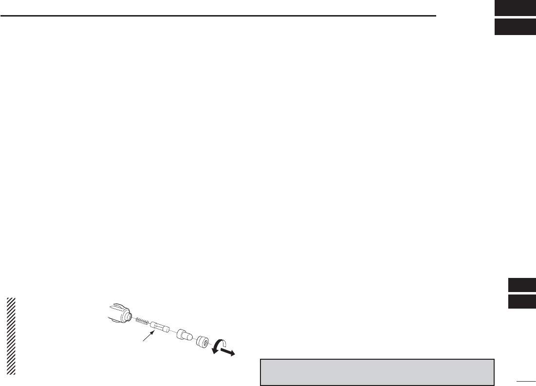
43
15
OPTIONS
2
4
5
7
8
9
DBATTERY CASE AND PACK
s"0(Li-ion BATTERY PAC K
The same as supplied with the transceiver.
Voltage : 7.2 V
Capacity : 2150 mAh (minimum)/2200 mAh (typical)
DCHARGERS
s"#DESKTOP CHARGER"#3!3%36AC ADAPTER
For rapid charging of battery packs. The same as supplied with the
transceiver. An AC adapter is supplied with the charger depending
on versions.
Charging time: Approximately 3 hours
s"#MULTI-CHARGER!$CHARGER ADAPTER (6 pcs.)
"#3AC ADAPTER
For rapid charging of up to 6 battery packs (six AD-129’s are
required) simultaneously. An AC adapter should be purchased
separately.
Charging time: Approximately 3 hours.
DC CABLES D
s#0(CIGARETTE LIGHTER CABLE
The same as supplied with some of the transceiver versions.
Specification: 12 V DC/1 A
NOTE: The CP-25H is
equipped with a 2 A
fuse. If the fuse blows,
replace it with a new
rated fuse. DO NOT
use a fuse with amp
ratings other than this
rating.
s/0#,/0#DC POWER CABLES
Charges the battery pack using 13.8 V power source instead of the
AC adapter.
OPC-515L: For BC-210
OPC-656 : For BC-197
DBELT CLIPS
s-"BELT CLIP
The same as supplied with the transceiver.
s-"SWIVEL BELT CLIP
Belt clip for swivel type.
s-".&&,LEATHER BELT HANGER
DOTHER OPTIONS
s(-SPEAKER-MICROPHONE
Full sized waterproof speaker-microphone including alligator type
clip to attach to your shirt or collar, etc.
s(-SPEAKER-MICROPHONE
The HM-202 meets IP67 requirements for waterproof protection.
Once the item has been dropped, the waterproof protection cannot be
guaranteed because of possible damage to the case or the waterproof
seals.
s&!36&!36FLEXIBLE ANTENNAS
*For only the USA, EXP, EUR, UK, FRG and HOL versions.
Approved Icom optional equipment is designed for optimal perfor-
mance when used with an Icom transceiver. Icom is not responsible
for the destruction or damage to an Icom transceiver in the event the
Icom transceiver is used with equipment that is not manufactured or
approved by Icom.
Available or applicable options may differ according to
countries. Ask your authorized dealer for details.
CP-25H : (2 A / 250 V)
Fuse

44
INDEX
– A –
About the function mode .................................................................17
AD-129 installation .........................................................................34
Adjusting the squelch level .............................................................13
AquaQuake water draining function................................................13
ATIS code confirmation...................................................................23
ATIS code programming .................................................................23
Attaching ...................................................................................35, 36
Attachments ......................................................................................2
Automatic recording function ..........................................................19
Automatic recording threshold level ................................................30
Auto power save function................................................................28
Auto scan function ..........................................................................27
AVERTISSEMENT POUR LES OPÉRATEURS RADIO .................. iv
– B –
Backlight function .....................................................................24, 27
BASIC OPERATION .........................................................................8
BATTERY CASE AND PACK ..........................................................43
Battery caution ...............................................................................31
BATTERY CHARGING ...................................................................31
Battery pack......................................................................................3
BC-210 installation .........................................................................33
Beep tone function ..........................................................................26
Belt clip .......................................................................................3, 43
– C –
Call channel ......................................................................................8
Call channel programming ..............................................................12
Channel 16 .......................................................................................8
Channel name programming ..........................................................21
Channel name scroll type ...............................................................28
Channel naming function ................................................................21
Channel selection .............................................................................8
CHARGERS ...................................................................................43
Charging ......................................................................................... 33
Charging caution ............................................................................32
COUNTRY CODE LIST .................................................................... v
– D –
DC CABLES ...................................................................................43
Description......................................................................................16
Detaching .......................................................................................35
Dual/Tri-watch function ...................................................................27
DUALWATCH/TRI-WATCH .............................................................16
– E –
Entering the function mode.............................................................17
EXPLICIT DEFINITIONS ...................................................................i
– F –
FCC INFORMATION ........................................................................ v
FEATURES ........................................................................................i
Flexible antenna ...............................................................................2
FOREWORD .....................................................................................i
Front, top and side panels ................................................................4
Function display ................................................................................6
FUNCTION MODE ITEMS .............................................................17
FUNCTION MODE OPERATION ...................................................17
– G –
General ..................................................................................... 38, 39
– H –
Handstrap .........................................................................................2
HM-167 descriptions.......................................................................36
– I –
IMPORTANT ...................................................................................... i
IN CASE OF EMERGENCY ............................................................ vi
– L –
LCD contrast selection ...................................................................28
Lock function ..................................................................................12

45
INDEX
2
4
5
7
8
9
– M –
Manual recording function ..............................................................18
Monitor function ..............................................................................12
Monitor key action...........................................................................27
– N –
NORMAL SCAN .............................................................................14
– O –
Opening comment entry function ...................................................22
Opening comment programming ....................................................22
OPERATING RULES ........................................................................1
Operation ........................................................................................ 16
Optional battery chargers ...............................................................34
OPTIONAL SPEAKER-MICROPHONE .........................................36
OPTIONAL SWIVEL BELT CLIP ....................................................35
OPTIONS .......................................................................................43
OTHER OPTIONS ..........................................................................43
– P –
PANEL DESCRIPTION .....................................................................4
Play back function...........................................................................20
PRECAUTIONS ................................................................................ ii
Priorities ...........................................................................................1
PRIORITY SCAN ............................................................................14
Priority scan function ......................................................................26
Privacy .............................................................................................. 1
– R –
Radio licenses ..................................................................................1
RADIO OPERATOR WARNING ...................................................... iii
Rapid charging with the BC-197+BC-157S or OPC-656 ................34
Receiver ...................................................................................38, 39
Receiving and transmitting .............................................................11
RECOMMENDATION ...................................................................... vi
RX bass boost function ...................................................................29
RX Noise Cancel function ...............................................................29
– S –
SCAN OPERATION ........................................................................14
Scan resume timer .........................................................................26
Scan types ......................................................................................14
Scrolling speed ...............................................................................28
SET MODE .....................................................................................25
SET MODE ITEMS ...................................................................25, 26
SET mode operation .......................................................................25
SET mode programming ................................................................25
Setting Favorite channels ...............................................................15
SPECIFICATIONS ..........................................................................38
Starting a scan ...............................................................................15
Supplied accessories........................................................................2
SUPPLIED ACCESSORIES AND ATTACHMENTS .........................2
Supplied battery charger ................................................................33
– T –
TABLE OF CONTENTS .................................................................. vii
Transmitter ................................................................................ 38, 39
TROUBLESHOOTING ....................................................................37
TX bass boost function ...................................................................29
TX Noise Cancel function ...............................................................29
– U –
Usable characters ...........................................................................21
U.S.A., International, Canadian and ATIS channels .........................9
– V –
VHF MARINE CHANNEL LIST .......................................................40
– W –
Weather alert function ....................................................................26
Weather channels ...........................................................................10

46
MEMO

47
MEMO
2
4
5
7
8
9
1-1-32 Kamiminami, Hirano-ku, Osaka 547-0003, Japan
A-7070D-1EX-e
Printed in Japan
© 2013–2014 Icom Inc.
< Intended Country of Use >
AT
FI
IT
PL
GB
RO
BE
FR
LV
PT
IS
TR
CY
DE
LT
SK
LI
HR
CZ
GR
LU
SI
NO
DK
HU
MT
ES
CH
EE
IE
NL
SE
BG
Printed on recycled paper with soy ink.