ICOM orporated 349500 VHF Marine Transceiver User Manual IC M73 M73EURO 3 indd
ICOM Incorporated VHF Marine Transceiver IC M73 M73EURO 3 indd
UserManual.wiki
>
ICOM orporated
>
349500 User Manual
>
User Manual_Updated
Contents
1.
User Manual
2.
Updated Manual
3.
User Manual_Updated
User Manual_Updated
Navigation menu
Upload a User Manual
Namespaces
Wiki Guide
HTML
PDF
Info
Views
User Manual
Discussion / Help
Navigation
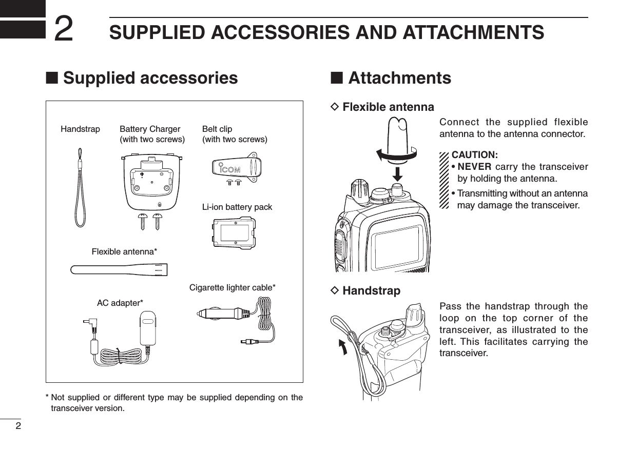
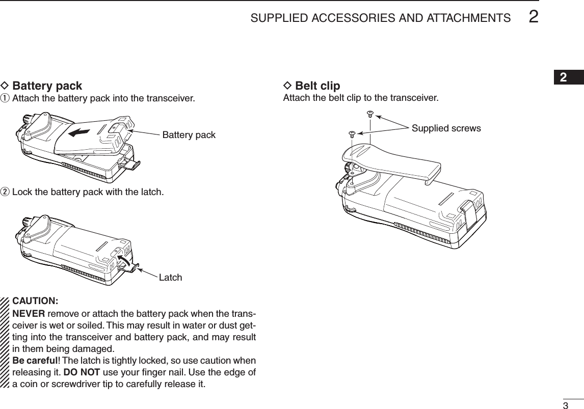
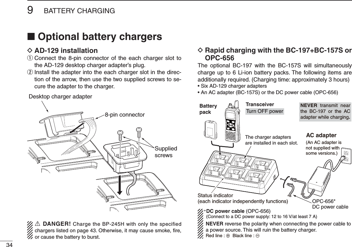
![iiRDANGER! NEVER short the terminals of the battery pack.RDANGER! Use and charge only specified Icom battery packs with Icom radios or Icom chargers. Only Icom battery packs are tested and approved for use with Icom radios or charged with Icom chargers. Using third-party or counterfeit battery packs or chargers may cause smoke, fire, or cause the battery to burst.RWARNING! NEVER connect the transceiver to an AC outlet. This may pose a fire hazard or result in an electric shock.RWARNING! NEVER hold the transceiver so that the an-tenna is closer than 2.5 cm (1 inch) from exposed parts of the body, especially the face or eyes, while transmitting. The trans-ceiver will perform best if the microphone is 5 to 10 cm (2 to 4 inches) away from the lips and the transceiver is vertical.CAUTION: NEVER connect the transceiver to a power source other than the products specified by Icom. Such a connec-tion will ruin the transceiver.CAUTION: MAKE SURE the flexible antenna and bat-tery pack are securely attached to the transceiver, and that the antenna and battery pack are dry before attachment. Exposing the inside of the transceiver to water will result in serious damage to the transceiver.BE CAREFUL! The transceiver meets IPX8 requirements for waterproof protection. However, once the transceiver has been dropped, waterproof protection cannot be guaranteed be-cause of possible damage to the transceiver's case or the water-proof seal.DO NOT use or place the transceiver in direct sunlight or in areas with temperatures below –20°C (–4°F) or above +60°C (+140°F) for the EXP/USA versions, below –15°C (+5°F) or above +55°C (+131°F) for the CHN/EUR/FRG/HOL/UK versions, and below –10°C (+14°F) or above +55°C (+131°F) for the AUS versions.DO NOT use harsh solvents such as benzine or alcohol when cleaning, as they will damage the transceiver surfaces.DO NOT push [PTT] when not actually intending to transmit.DO NOT modify the transceiver. The transceiver warranty does not cover any problems caused by unauthorized modification.DO NOT operate the transceiver near unshielded electrical blasting caps or in an explosive atmosphere.KEEP the transceiver out of the reach of children.KEEP the transceiver at least 0.9 meter (3.0 feet) away from your vessel’s magnetic navigation compass.PRECAUTIONSIcom, Icom Inc. and the Icom logo are registered trademarks of Icom Incorporated (Japan) in Japan, the United States, the United Kingdom, Germany, France, Spain, Russia and/or other countries.](https://usermanual.wiki/ICOM-orporated/349500.User-Manual-Updated/User-Guide-2222595-Page-3.png)
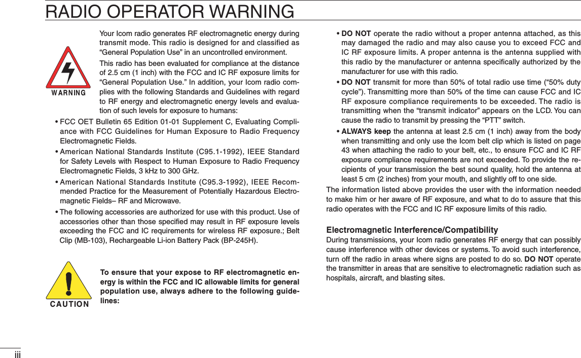
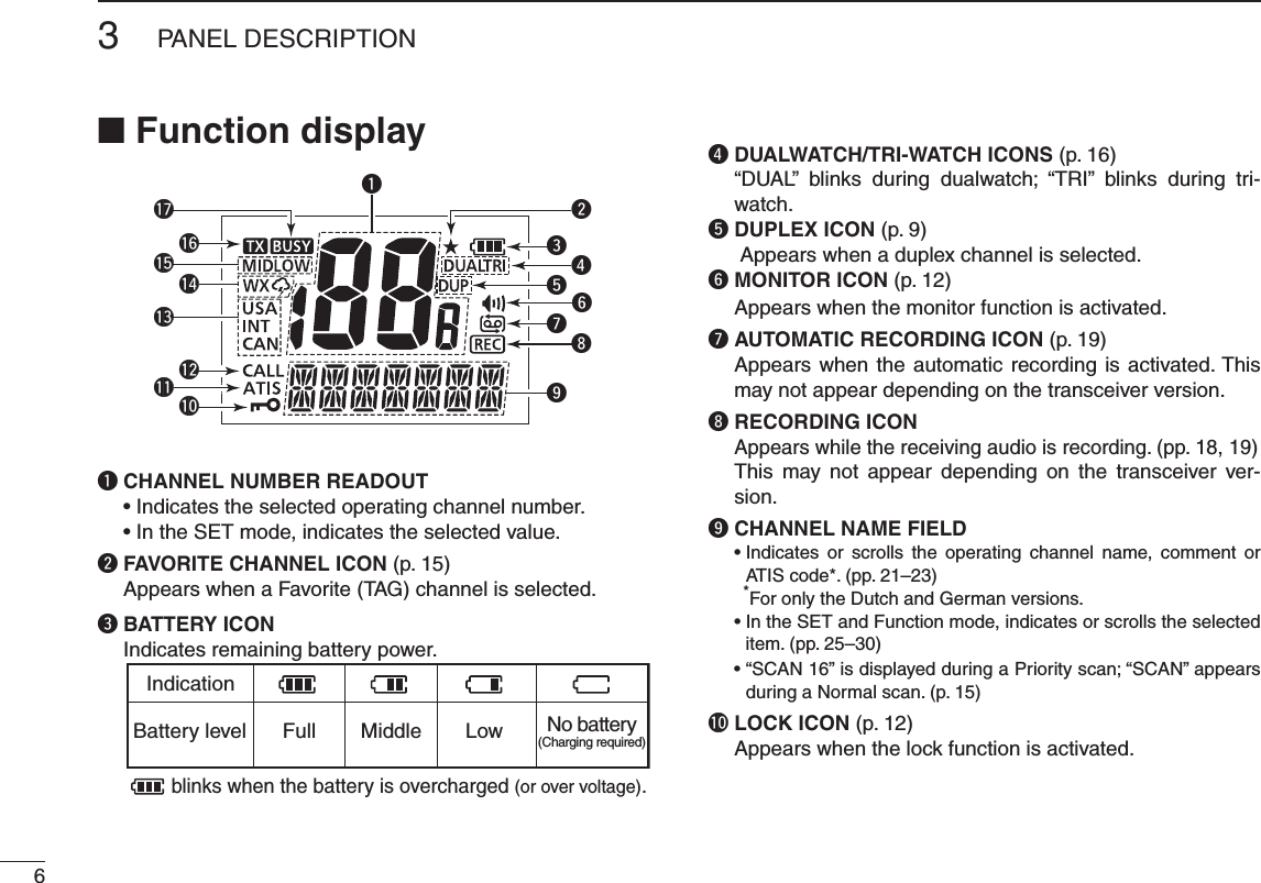
![4PANEL DESCRIPTION3N Front, top and side panelsqweytrMicrophone!2!1!0ouiSpeakerFunctiondisplay (p. 6)q VOLUME CONTROL [VOL] Turns ON power and adjusts the audio level.w PTT SWITCH [PTT] Hold down to transmit; release to receive.e MONITOR KEY [] s-ANUALLYOPENSTHESQUELCHTOMONITORTHECHANNELWHILEheld down. (p. 12) s0USHTHISSWITCHTHENADJUSTTHESQUELCHLEVELWITH;Y]/[Z]. (p. 13)s7HILEHOLDINGDOWNTHISSWITCHTURNTHE/.POWERTOenter the SET mode. (p. 25)r #(!..%,+%9;#= s3ELECTS#HANNELWHENPUSHEDP sSelects the Call channel when pushed for 1 second. (p. 8) sEnters the Call channel write mode when the Call channel is selected and this key is held down for 3 seconds. (p. 12)t FUNCTION KEY [F] s%NTERSTHE&UNCTIONMODEWHENPUSHEDPs4HE!QUA1UAKEFUNCTIONISACTIVATEDWHENHELDDOWNFOR1 second. (p. 13)s7HILEHOLDINGDOWNTHISKEYTURN/.THEPOWERTOENTERthe recording counter mode.](https://usermanual.wiki/ICOM-orporated/349500.User-Manual-Updated/User-Guide-2222595-Page-12.png)
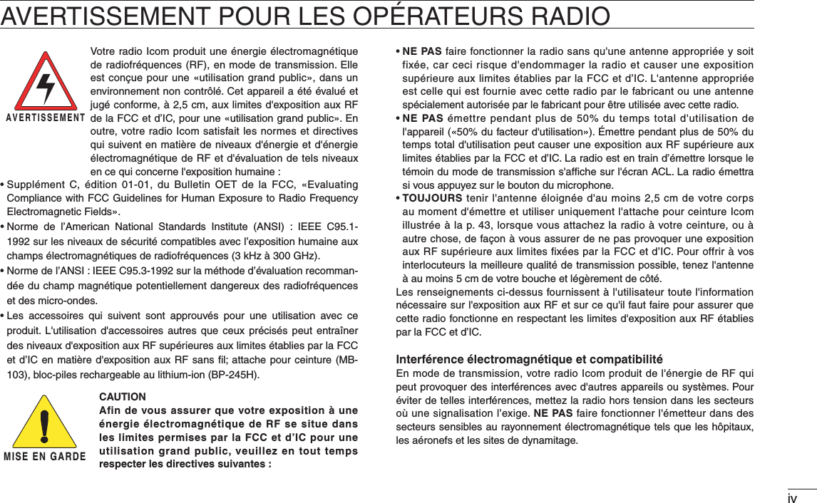
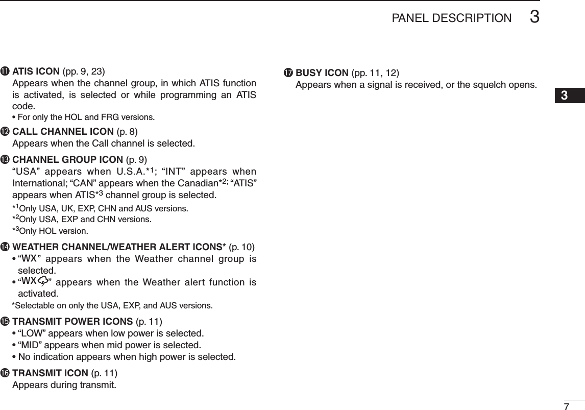
![53PANEL DESCRIPTION245789y 3#!.+%9;3#!.s$5!,= s3TARTSANDSTOPSNORMALORPRIORITYSCANWHENPUSHED (pp. 14, 15) s%NTERSTHE7ATCHMODEWHENHELDDOWNFORSECOND (p. 16)u CHANNEL/WEATHER CHANNEL KEY ;#(78s5)#=)#-;#(=)#%52/ s3ELECTSANDTOGGLESTHEREGULARCHANNELSANDWEATHERchannel* when pushed. (pp. 9, 10) s3ELECTS THE 53! )NTERNATIONAL #ANADIAN OR !4)3channel group* when held down for 1 second. (p. 9) - The function display shows which channel group is active. s0USHTORETURNTOTHEDISPLAYBEFOREYOUSELECTEDTHEchannel when the priority channel or the Call channel is selected. * Selectable contents differ depending on the transceiver version. NOTE: ;#(78s5)#= and [CH] are described as [CH/78s5)#= in this instruction manual.i CHANNEL UP/DOWN KEYS [Y]/[Z] s3ELECTSTHEOPERATINGCHANNELPPn s3ELECTSTHE3%4MODEOPTIONOFTHEITEMP sSelects the SET mode item when pushed along with []. (p. 25) s#HECKS &AVORITE 4!' CHANNELS OR CHANGES THEscanning direction during a scan. (p. 15) s3ELECTSTHE&UNCTIONMODEITEMPo 42!.3-)40/7%2,/#++%9;(,s,/#+= s3ELECTSHIGHMIDDLEORLOWPOWERWHENPUSHEDPs4OGGLESTHELOCKFUNCTION/./&&WHENHELDDOWNFORsecond. (p. 12)!0 &!6/2)4%4!'+%9;&!6s(] s0USHTHISKEYTOSEQUENTIALLYSELECTTHE&AVORITE4!'channels, while ignoring untagged channels, in a channel group. (p. 15) s(OLDDOWNFORSECOND TOSETOR CLEARTHEDISPLAYEDchannel as a Favorite (TAG) channel. (p. 15)s7HILEHOLDINGDOWNTHISKEYTURN/.POWERTOCLEARORset all Favorite (TAG) channels in the selected channel group. (p. 15)!1 SPEAKER-MICROPHONE CONNECTOR [SP MIC] Connects the optional external speaker-microphone. (p. 36) NOTE: Attach the [SP MIC] cap when the optional speaker-microphone is not used.!2 ANTENNA CONNECTOR Connects the supplied antenna. (p. 2)](https://usermanual.wiki/ICOM-orporated/349500.User-Manual-Updated/User-Guide-2222595-Page-13.png)
![8BASIC OPERATION4N Channel selectionIMPORTANT!: Prior to using the transceiver for the first time, fully charge the battery pack. This will help maximize the capability and life of the battery. To avoid damage to the transceiver, turn OFF the radio while charging. D#HANNELChannel 16 is the distress and safety channel. It is used for establishing initial contact with another station, and for emer-gency communications. Channel 16 is automatically moni-tored during both Dualwatch and Tri-watch. While standing by, you must monitor Channel 16.q Push ;#= to select Channel 16.w Push ;#(78s5)#= to return to the condition before selecting Channel 16, or push [Y]/[Z] to select the operating channel.Push DCall channelEach regular channel group has separate leisure-use call channels. The Call channel is monitored during Tri-watch. The Call channels can be reprogrammed (p. 12) and may be used to store your most often-used channels in each channel group for quick recall.q Hold down ;#= for 1 second to select the Call channel. sh#!,,vANDTHECALLCHANNELNUMBERAPPEARs4HE#ALLCHANNELCANBEREPROGRAMMED3EETHEh#ALLCHANNEL programming” on page 12 for details.w Push ;#(78s5)#= to return to the screen before you selected Call channel, or push [Y]/[Z] to select an operating channel.Hold downfor 1 second](https://usermanual.wiki/ICOM-orporated/349500.User-Manual-Updated/User-Guide-2222595-Page-16.png)
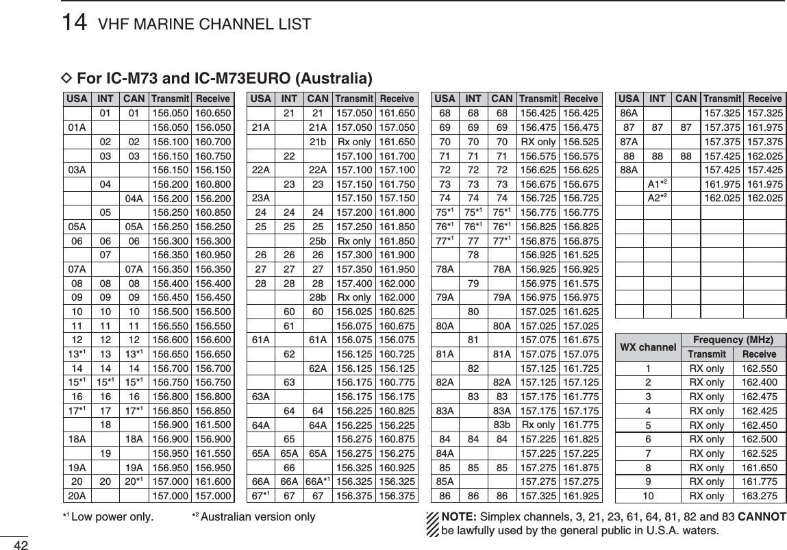
![94BASIC OPERATION245789 DU.S.A., International, Canadian and ATIS channelsThe transceiver has U.S.A.*1, International, Canadian*2 and ATIS*3 channels. You must select the proper channels for the operating area.*1Only USA, UK, EXP, CHN and AUS versions.*2Only USA, EXP and CHN versions.*3Only HOL version.Push q;#(78s5)#= to select a regular channel. s)FTHEWEATHERCHANNELAPPEARSPUSH;#(78s5)#= again.Push w[Y]/[Z] to select a channel. sh$50vAPPEARSFORDUPLEXCHANNELS e To change the channel group, hold down ;#(78s5)#= for 1 second. s2EPEATUNTILYOUREACHTHEDESIREDCHANNELGROUPFor U.K. and Australia versionsU.S.A. channelsInternational channelsHold downfor 1 secondHold downfor 1 secondHold down for 1 secondHold downfor 1 secondHold downfor 1 secondFor Dutch versionFor U.S.A., Export, and China versionsInternational channelsInternational channelsU.S.A. channelsATIS channelsCanadian channels](https://usermanual.wiki/ICOM-orporated/349500.User-Manual-Updated/User-Guide-2222595-Page-17.png)
![104BASIC OPERATION DWeather channelsThe transceiver has 10 pre-programmed weather channels*. These are used for monitoring broadcasts from NOAA (Na-tional Oceanographic and Atmospheric Administration.) The transceiver can automatically detect a weather alert tone on the selected weather channel or while scanning.See the “SET mode items” on page 26 for details.* For only the USA, EXP, and AUS versions. Push q;#(78s5)#= to select the weather channel group.Push w[Y]/[Z] to select a weather channel. Push e;#(78s5)#= to return to the screen before you selected the Weather channel group.](https://usermanual.wiki/ICOM-orporated/349500.User-Manual-Updated/User-Guide-2222595-Page-18.png)
![114BASIC OPERATION245789N Receiving and transmittingCAUTION: Transmitting without an antenna may damage the transceiver.Rotate q[VOL] clockwise to turn ON power. s!NOPENINGCOMMENTSCROLLSACROSSTHEFUNCTIONDISPLAY s0USH;#= to skip the opening comment.Set the volume and squelch level. w ± Push [], and push [Z] to open the squelch. ± Rotate [VOL] to set the volume level. ± Push [], and push [Y]/[Z] to set the squelch level.Push e[Y]/[Z] to select the desired channel. s0USHING;&!6s(] selects only Favorite channels.- When receiving a signal, the “ ” icon appears while audio is heard from the speaker.- Further adjustment of [VOL] may be necessary at this point. Push r;(,s,/#+= to select the output power, if necessary.- “LOW” appears when low power is selected; “MID” appears when mid power is selected; no indication is displayed when high power is selected.- Choose low or mid power to conserve battery power; choose high power for longer distance communications.- Some channels are for only low transmission. t Hold down [PTT] to transmit, and speak at your normal voice level.- The appears while transmitting.- Channel 70 cannot be used for transmission.Release y[PTT] to receive.IMPORTANT: To maximize the readability of your transmit-ted signal, pause a second after pushing [PTT]. Hold the microphone 5 to 10 cm (2 to 4 inches) from your mouth, and speak at your normal voice level.NOTE: The transceiver has a power save function to con-serve the battery power. The power save function automati-cally activates when no signal is received for 5 seconds.To prevent accidental prolonged transmission, the trans-ceiver has a time-out timer function*. This timer cuts OFF a transmission after 5 minutes of continuous transmission.* For only the USA and AUS versions.q Power ONw Set the volumew Set the squelch levelw Set the squelch levele Select the channelr Set the output powert Push to transmity Release to receiveMicrophoneSpeaker](https://usermanual.wiki/ICOM-orporated/349500.User-Manual-Updated/User-Guide-2222595-Page-19.png)
![124BASIC OPERATION12N Call channel programmingThe Call channel key is used to select Channel 9* by default. However, you can program your most often-used channel in each channel group for quick recall. * The channel may differ, depending on the transceiver version. Hold down q;#(78s5)#= for 1 second several times to select the desired channel group (USA, INT, CAN, ATIS) to be programmed. w Hold down ;#= for 1 second to se-lect the Call channel.sh#!,,v AND #ALL CHANNEL NUMBER AP-pear. Hold down e;#= again for 3 sec-onds (until a long beep changes to 2 short beeps) to enter the Call channel programming mode.s4HE #ALL CHANNEL NUMBER TO BE PRO-grammed blinks. r Push [Y]/[Z] to select the desired channel. Push t;#= to program the displayed channel as the Call channel.s4HE#ALLCHANNELNUMBERSTOPSBLINKINGN Lock functionThis function electronically locks all keys (except for [PTT], [ ] and ;(,s,/#+=) to prevent accidental channel changes and function access.± Push ;(,s,/#+= for 1 second to turn the lock function ON or OFF.Hold downfor 1 secondAppears while the lockfunction is in use.N Monitor functionThe monitor function releases the noise squelch mute to check the volume level. See page 27 for details of the monitor switch action.± Hold down [] for 1 second to activate the monitor func-tion.sh ” and “ ” appear and audio is heard.Appears while the monitor function is in use.Hold downfor 1 second](https://usermanual.wiki/ICOM-orporated/349500.User-Manual-Updated/User-Guide-2222595-Page-20.png)
![134BASIC OPERATION245789N Adjusting the squelch levelTo adjust the transceiver’s squelch level, use the [Y]/[Z] keys, as described below. In order to properly receive signals, as well as for the scan to function effectively operate, the squelch must be adjusted to the proper level.q Push [], then adjust the squelch level with [Y]/[Z]. - “SQL” and the squelch level are displayed. - There are 11 squelch levels to choose from: OP is completely open; 10 is tight squelch; 1 is loose squelch level. - When no key is pushed for 5 seconds, the transceiver returns to its normal condition.w Push [] again to return to normal operating mode.Push Shows the squelchlevel.Appears during squelch level adjustmentN AquaQuake water draining functionThe AquaQuake water draining function clears water away from the speaker grill. Without this function, water may muffle the sound coming from the speaker. The transceiver emits a vibrating beep when this function is activated.± While holding down [F], the AquaQuake function is acti-vated to clear water away from the speaker grill. s"EEPSOUNDSREGARDLESSOFTHEVOLUMELEVELSETTING s!CTIVATESFORSECONDSINMAXIMUMTODRAINWATERs4HETRANSCEIVERNEVERACCEPTSKEYOPERATIONWHILETHE!QUA1UAKEfunction is activated.s4HE !QUA1UAKE FUNCTION CAN NOT BE ACTIVATED WHEN AN OPTIONALspeaker-microphone is connected.](https://usermanual.wiki/ICOM-orporated/349500.User-Manual-Updated/User-Guide-2222595-Page-21.png)
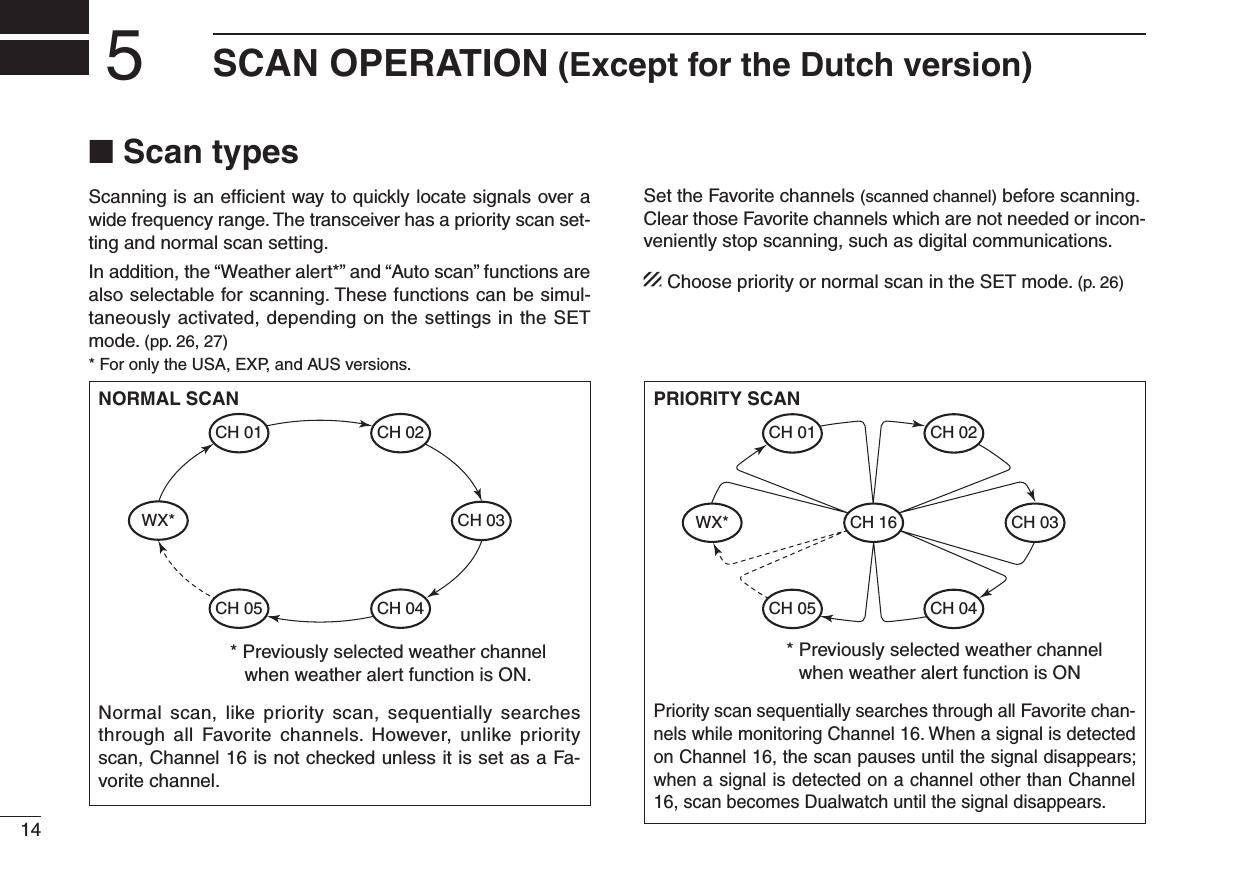
![155SCAN OPERATION (Except for the Dutch version)245789N Setting Favorite channelsFor more efficient scanning, add desired channels as Favorite channels, or clear the Favorite for unwanted channels.Untagged channels will be skipped during scanning. Favor-ite channels can be independently assigned to each channel group (USA, INT, CAN, ATIS) independently.Select the desired channel to set as a Favorite channel. q Hold down w;&!6s(] for 1 second to set the displayed chan-nel as a Favorite channel.sh(” appears on the function display. To cancel the Favorite channel setting, hold down e;&!6s(] for 1 second.sh(” disappears.#LEARINGORSETTING!LL&AVORITE#HANNELSINTHE 3E-lected Channel GroupWhile holding down ;&!6s(], turn ON power to clear all the Favorite channel settings in the channel group.s2EPEATABOVEPROCEDURETOSETALLCHANNELSAS&AVORITECHANNELSN Starting a scanFirst, set the weather alert function, priority scan function, scan resume timer and auto scan function, using the SET mode. (pp. 26, 27)q Make sure the desired channel group (e.g., USA, CAN, INT, ATIS) is selected. Move between channel groups by repeat-edly pushing ;#(78s5)#= for 1 second at a time.s7HENTHEWEATHERALERTFUNCTIONISINUSESELECTTHEDESIREDweather channel with ;#(78s5)#= and [Y]/[Z]. * For only the USA, EXP, and AUS versions.w Push ;3#!.s$5!,= to start a priority or normal scan. sh3#!.vBLINKSINTHEFUNCTIONDISPLAY shvAPPEARSONTHECOMMENTINDICATORDURINGAPRIORITYSCANsWhen a signal is received, the scan pauses until the signal dis-appears, or resumes after pausing 5 seconds, depending on the scan resume timer setting. (Channel 16 is still monitored during a priority scan.) s0USH [Y]/[Z] to check the scanning of Favorite channels, change the scanning direction or resume the scan manually.e To stop the scan, push ;3#!.s$5!,=. sh3#!.vDISAPPEARSScan starts“SCAN” indication blinksPush Pushto stop the scanWhen receiving a signal, “SCAN” indica-tion blinks and audio is heard.[Example]: Starting a normal scan.](https://usermanual.wiki/ICOM-orporated/349500.User-Manual-Updated/User-Guide-2222595-Page-23.png)
![16DUALWATCH/TRI-WATCH6N DescriptionDualwatch monitors Channel 16 while you are receiving on another channel; Tri-watch* monitors Channel 16 and the call channel while receiving on another channel. *For the Dutch transceiver version Only Dualwatch can be used. N Operationq Select a desired operating channel.w Hold down ;3#!.s$5!,= for 1 second to start Dualwatch or Tri-watch (depending on the SET mode setting; p. 27). sh$5!,vBLINKSDURING$UALWATCHh42)vBLINKSDURING4RIWATCH s!BEEPTONESOUNDSWHENASIGNALISRECEIVEDON#HANNELs4RIWATCHBECOMES$UALWATCHWHENRECEIVINGASIGNALONTHECall channel.e To cancel Dualwatch/Tri-watch, push ;3#!.s$5!,= again.DUALWATCH/TRI-WATCH SIMULATIONDualwatch Tri-watchCallchannelCh 88Ch 16 Ch 88 Ch 16 Ch 88 Ch 9s)FASIGNALISRECEIVEDON#HANNEL$UALWATCH4RIWATCHpauses on Channel 16 until the signal disappears.s)FASIGNALIS RECEIVEDON THE #ALLCHANNELDURING4RIwatch, Tri-watch becomes Dualwatch until the signal dis-appears.s4OTRANSMITONTHESELECTEDCHANNELDURING$UALWATCHTri-watch, hold down [PTT].[Example]: Operating tri-watch on INT channel 07.A signal is received on the Call channel.A signal received on Channel 16 always takes priority.Tri-watch resumes after the signal disappears.Tri-watch starts.Hold down for 1 second](https://usermanual.wiki/ICOM-orporated/349500.User-Manual-Updated/User-Guide-2222595-Page-24.png)
![177FUNCTION MODE OPERATION245789N About the function modeThere are 7 transceiver functions‡ in the function mode: Play back function‡, Manual recording function‡, Automatic record-ing function‡, backlight function, channel naming function, opening comment entry function and the ATIS code program-ming function†.†For only the Dutch and German versions.‡Depending on versions.D Entering the function modePush q[F] to enter the function mode. sh0,!9v0LAYBACKFUNCTIONAPPEARSs7HENNOKEYISPUSHEDFORSECONDSTHETRANSCEIVERRETURNSTO its normal condition. w Push [Y]/[Z] to select the desired item. e Push ;(,s,/#+= to select or decide the desired option of the item. s3OMEITEMSEXITTHEFUNCTIONMODEWHENPUSHING;(,s,/#+=.To exit the function mode, push r[F].D FUNCTION MODE ITEMSPlayback function*,‡Manual recordingfunction‡Automatic recordingfucntion‡Backlight functionATIS code programmingfunction†Opening commententry functionChannel namingfunction: Push [Y] : Push [Z] *Starting item†For only the Dutch and German versions.‡Depending on versions.](https://usermanual.wiki/ICOM-orporated/349500.User-Manual-Updated/User-Guide-2222595-Page-25.png)
![187FUNCTION MODE OPERATIONYou can record the received signal whenever you want by us-ing the manual recording function.This function can record the received signal for maximum 30 seconds. The transmitted signal cannot be recorded. The previously recorded signal will be overwritten when you re-cord the next audio using this function. q Push [F] to enter the function mode, and then push [Y]/[Z] to select the manual recording function. sh-2%#vAPPEARS w Push ;(,s,/#+= to start record-ing. sh2%#vAPPEARS s7HEN THE SIGNAL DISAPPEARS THEtransceiver continues recording without audio.Push e[F] to stop the recording. s4HERECORDINGWILLAUTOMATICALLYSTOPafter 30 seconds.Manual recordingmode appears.“REC” appears while recording.Example: 20 seconds30 secondsWhen receiving a signal for 30 seconds or less, this function records all contents.30 seconds after you start the manual recording, the recording will automatically stop.These contentswill not be recorded.Start manualrecording.Start manualrecording.Stop manualrecording.Automatically stopsrecording.N -ANUALRECORDINGFUNCTION$EPENDINGONVERSIONS](https://usermanual.wiki/ICOM-orporated/349500.User-Manual-Updated/User-Guide-2222595-Page-26.png)
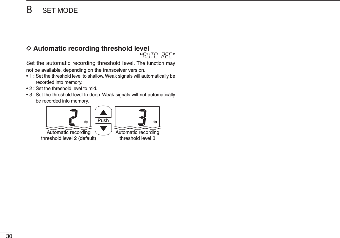
![197FUNCTION MODE OPERATION245789When this function is turned ON, the transceiver automati-cally records the received signal into the memory.The maximum recording time is 60 seconds.s4HETRANSMITSIGNALCANNOTBERECORDEDs)FASIGNALLESSTHANSECONDSISRECORDEDTHENEXTRECORDEDSIG-nal is added into the same data.s4HERECORDINGTHRESHOLDLEVELCANBESETINTHESETMODE3EEPAGE30 for details. NOTE: Even if you turn OFF the transceiver, this function remains ON. Push q[F] to enter the function mode, and then push [Y]/[Z] to select the automatic recording function. sh!2%#vAPPEARS w Push ;(,s,/#+= to turn the function ON or OFF.s4HE AUTOMATIC RECORDING ICON AP-pears when the function is turned ON. s!FTERPUSHING;(,s,/#+=, exits the function mode. e When a signal is received, the transceiver automatically starts recording. sh2%#vAPPEARSWHILERECORDING s4HERECORDINGWILLAUTOMATICALLYSTOPwhen the received signal disap-pears, or the received signal strength becomes weaker than the set threshold level in the set mode (p. 30).Automatic recordingmode appears.“REC” is appeared while recording.Automatic recording icon appears.Example: 40 seconds60 secondsWhen receiving a signal for 60 seconds or less, this function records all contents.After 60 seconds has passed from starting the automatic recording, this function records the 60 seconds before stopping to record.These contentswon’t be recorded.Starts recordingStarts recordingStops recordingStops recordingN !UTOMATICRECORDINGFUNCTION$EPENDINGONVERSIONS](https://usermanual.wiki/ICOM-orporated/349500.User-Manual-Updated/User-Guide-2222595-Page-27.png)
![207FUNCTION MODE OPERATIONThis transceiver has two voice recorders.One is the manual recording function which can record for 30 seconds. The other is the automatic recording function which can record the last 60 seconds of the receiving signal.There are three play-back modes as follows. Push q[F] to enter the function mode. sh0,!9vAPPEARS Push w;(,s,/#+=to enter the play back selection mode, and then push [Y]/[Z] to select the desired play back mode from “M-PLAY,” “LAST30S,” or “LAST60S.” If there is no recorded signal in the transceiver, “BLANK” appears. s-0,!9 0LAY BACK THE MANUALLYrecorded signal. s,!3430LAY BACK THE LAST seconds of the automati-caliy recorded signal. s,!3430LAY BACK THE AUTOMATI-caliy recorded signal for 60 seconds. Push e;(,s,/#+= to play back the recorded signal. sh0,vBLINKSs4O STOP THE PLAY BACK PUSH;(,s,/#+= again. DO NOT detach the battery pack while the transceiver is turned ON. Other-wise, the data could be lost or delet-ed.Deleting a recorded signal: While selecting the desired data to delete, hold down ;&!6s(] for 3 seconds until 2 short beeps sound. Blinks while playbacking.Playback mode appears.“BLANK” appears when the transceiver has no recorded signal.dingdingdingPlaying back for 30 seconds (maximum).Select “M-PLAY”Select “LAST60S”Select “LAST30S”Not playing back.Playing back for 60 seconds (maximum).Playing back for 30 seconds (maximum).N 0LAYBACKFUNCTION$EPENDINGONVERSIONS](https://usermanual.wiki/ICOM-orporated/349500.User-Manual-Updated/User-Guide-2222595-Page-28.png)
![217FUNCTION MODE OPERATION245789N Channel naming functionThe IC-M73/IC-M73EURO can assign up to 10-character channel names for each operating channel, including each weather channel. This provides easy recognition of the chan-nel in use, or station names.When shipped from the factory, the IC-M73/IC-M73EURO is programmed with default names for each VHF marine chan-nel. These defaults can be changed, if desired. DUsable characters DChannel name programming Push q[Y]/[Z] to select a channel to program. s(OLDDOWN;#(78s5)#= for 1 second to select a channel group, if necessary. Push w[F] to enter the function mode, and then push [Y]/[Z] to select the channel naming function. sh#(.!-%vAPPEARS e Push ;(,s,/#+=to edit the channel name. s4HE ST CHARACTER OF THE CURRENTLY PRO-grammed name blinks.Push r[Y]/[Z] to select a character. Push t;#(78s5)#= to move to the right; then push [Y]/[Z] to select a character. s0USH;3#!.s$5!,= to move to the left. Continue until the desired charac- yters have been selected, then push ;(,s,/#+= to return to normal op-eration.Deleting a channel name (All clear): While selecting the desired channeI name in the channel name editing mode, push ;&!6s(] to delete the selected channel name. (=)(4)(D)(N)(X)(h)(r)()(5)(E)(O)(Y)(i)(s)(+)(6)(F)(P)(Z)(j)(t)(7)(G)(Q)(a)(k)(u)(,)(8)(H)(R)(b)(l)(v)(/)(9)(I)(S)(c)(m)(w)(0)(Space)(J)(T)(d)(n)(x)(1)(A)(K)(U)(e)(o)(y)(2)(B)(L)(V)(f)(p)(z)(3)(C)(M)(W)(g)(q)(–)](https://usermanual.wiki/ICOM-orporated/349500.User-Manual-Updated/User-Guide-2222595-Page-29.png)
![227FUNCTION MODE OPERATIONThe IC-M73/IC-M73EURO can assign up to 16-character opening comments.You may replace the factory-set opening comment with a comment of your own. The opening comment appears each time the IC-M73/IC-M73EURO is powered ON. The comment may be up to 16 characters long.You can use same characters as “Channel naming function.” (p. 21) DOpening comment programming Push q[F] to enter the function mode, and then push [Y]/[Z] to select the channel naming function. sh/#%$)4vAPPEARS w Push ;(,s,/#+= to edit the open-ing comment. s4HE ST CHARACTER OF THE CURRENTLY PRO-grammed comment blinks.Push e[Y]/[Z] to select a character. r Push ;#(78s5)#= to move to the right; then push [Y]/[Z] to select a character. s0USHING;3#!.s$5!,=, moves to left. Continue until the desired charac- iters have been entered, then push ;(,s,/#+= to return to normal op-eration.Deleting the opening comment (All clear): While in the opening comment editing mode, push ;&!6s(] to delete. The programmed opening comment is briefly displayed or scrolled when the transceiver is powered ON.However, the opening comment display can be skipped by pushing ;#=.N Opening comment entry function](https://usermanual.wiki/ICOM-orporated/349500.User-Manual-Updated/User-Guide-2222595-Page-30.png)
![237FUNCTION MODE OPERATION245789The 10-digit ATIS code can be programmed and confirmed with the following operation.The ATIS code programming is not necessary and con-firmation can only be performed when the ATIS code has been programmed by your dealer. The code programming can be performed 1 time only, if the code has not been programmed by your dealer. Push q[F] to enter the function mode, and then push [Y]/[Z] to select the ATIS code programming function. sh!4)3)$vAPPEARS w Push ;(,s,/#+= to edit the ATIS code. sh)DvANDh!4)3vAPPEARANDTHESTCHAR-acter of the code blinks. Push e[Y]/[Z] to select a number. r Push ;#(78s5)#= to move to the right; then push [Y]/[Z] to select a number. s0USH ;3#!.s$5!,= to move to the left. After inputting the 10-digit ATIS tcode, push ;(,s,/#+= to write the code into the memory, then goes to the ATIS code confirma-tion mode.Deleting the ATIS code (All clear): While in the ATIS code editing mode, push ;&!6s(] to de-lete. DATIS code confirmation 7HENTHE!4)3CODEHASBEENPROGRAMMED Push q[F] to enter the function mode, and then push [Y]/[Z] to select the ATIS code programming function. sh!4)3)$vAPPEARS w Push ;(,s,/#+=to confirm the ATIS code. sh)DvANDh!4)3vAPPEARs4HE !4)3 CODE IS DISPLAYED ANDscrolls in the channel comment dis-play. e Push ;(,s,/#+= to return to normal operation.. ScrollsN ATIS code programming &ORONLYTHE$UTCHAND'ERMANVERSIONSScrolls](https://usermanual.wiki/ICOM-orporated/349500.User-Manual-Updated/User-Guide-2222595-Page-31.png)
![247FUNCTION MODE OPERATIONN Backlight functionThis function is convenient for nighttime operation. The back-lighting can also be turned OFF in the SET mode. (p. 27)± Push any key other than [PTT] to turn ON the backlighting.s4HEBACKLIGHTINGISAUTOMATICALLYTURNED/&&AFTERSECONDSOF inactivity. Push q[F] to enter the function mode, and then push [Y]/[Z] to select the backlighting function. sh,)'(4vAPPEARS w Push ;(,s,/#+= to turn the func-tion ON or OFF. s!FTER PUSHING ;(,s,/#+=, exits from the function mode. Backlight modeappears.](https://usermanual.wiki/ICOM-orporated/349500.User-Manual-Updated/User-Guide-2222595-Page-32.png)
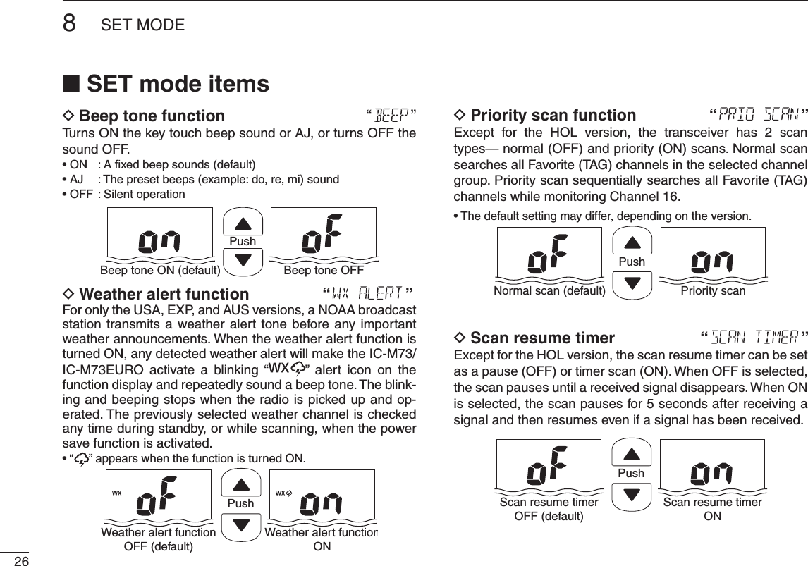
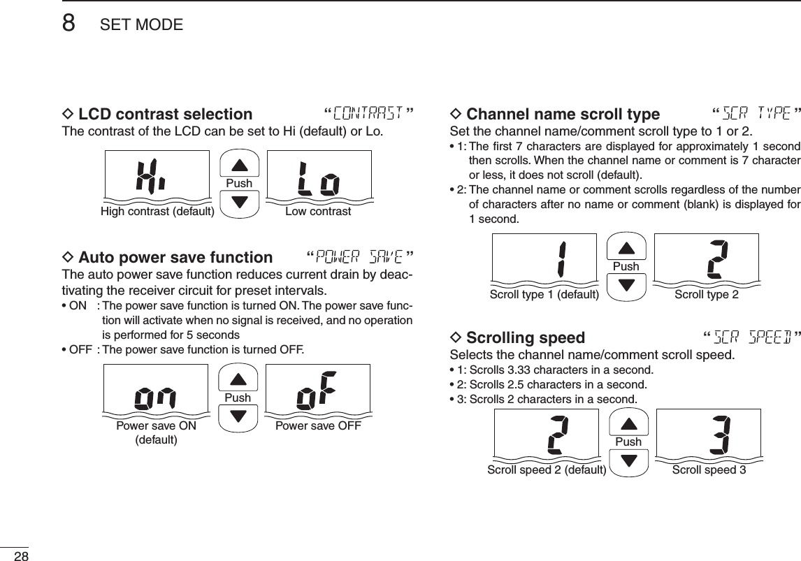
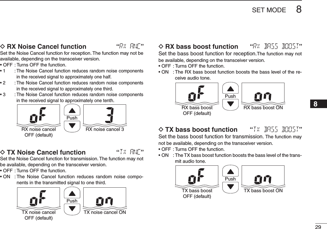
![258SET MODE245789N SET mode programmingThe SET mode is used to change the status of 17 transceiver functions†: Beep tone function, Weather alert function†, Prior-ity scan, Scan resume timer, Auto scan start function, Dual/Tri-watch function, Monitor key action, Display backlight, LCD contrast selection, Power save function, Scroll type selection, Scroll speed selection, RX noise cancel function†, TX noise cancel function†, RX bass boost function†, TX bass boost function† and the Automatic recording threshold level selec-tion†. DSET mode operationTurn OFF power. q w While holding down [], turn ON power to enter the SET mode. s4HEh"%%0v"EEPTONEFUNCTIONSETTINGAPPEARS e Push [], or push [ ] and [Y]/[Z] to select the desired item.Push r[Y]/[Z] to select the desired option of the item.To exit the SET mode, push t;#=. DSET MODE ITEMSBeep tone function* Weather alert function†Priority scan†Scan resume timer†Auto scan start function†Dual/Tri-watchfunction†Monitor keyactionDisplaybacklightLCD contrastselectionAutomtic recordingthreshold level selection†TX bass boost function†RX bass boost function†Power save functionScroll type selectionScroll speed selectionRX noise cancel function†TX noise cancel function†: Push [ ], or while holding down [ ], push [Y]: While holding down [ ], push [Z]*Starting item†Depending on versions](https://usermanual.wiki/ICOM-orporated/349500.User-Manual-Updated/User-Guide-2222595-Page-33.png)
![278SET MODE245789 DAuto scan function “ ”Except for the HOL version, the auto scan function automati-cally starts the desired scan when no signal is received, and no operation is performed for 30 secondsPushAuto scan OFF (default) Auto scan ON DDual/Tri-watch function “ ”Except for the HOL version, this item selects Dual or Tri-watch as desired. See page 16 for details.PushDualwatch (default) Tri-watch DMonitor key action “ ”The monitor key action temporarily cuts off the squelch func-tion. This key action contains PUSH (Pu) or HOLD (Ho) set-tings, as shown below.s0U053(!FTER PUSHING [] for 1 second, the squelch opens and audio is heard. The squelch is held open while con-tinuously holding down [ ]. (default)s(O(/,$!FTER PUSHING [ ] for 1 second, the squelch opens and audio is heard even if [ ] is released. To close the squelch, push any key.PushPush setting (default) Hold settingBacklight function “ D”This function is convenient for nighttime operation. The back-light can be turned ON or OFF.s4HE BACKLIGHT IS AUTOMATICALLY ACTIVATED WHEN ANY KEY EXCEPT FOR[PTT] is pushed.s4HEBACKLIGHTISAUTOMATICALLYTURNED/&&AFTERSECONDSOFINAC-tivity.PushBacklight ON(default)Backlight OFF](https://usermanual.wiki/ICOM-orporated/349500.User-Manual-Updated/User-Guide-2222595-Page-35.png)
![36OPTIONAL SPEAKER-MICROPHONE11N (-DESCRIPTIONSHM-202 is also an optional speaker microphone. see the page 43 for details.NEVER immerse the connector in water. If the connector becomes wet, be sure to dry it BEFORE attaching it to the transceiver.NOTE: The microphone is located at the top of the speak-er-microphone, as shown in the diagram above. To maxi-mize the readability of your transmitted signal (voice), hold the microphone approximately 5 to 10 cm (2 to 4 inches) from your mouth, and speak in a normal voice level.N AttachingInsert the speaker-mic connector onto the [SP MIC] connec-tor and carefully screw it tight, as shown in the diagram below. Be careful not to cross-thread the connection.Set the triangle mark to the front side.CAUTION: Attach the speaker- microphone’s connector securely to prevent accidental dropping, or water intrusion in the connector.Detaching:Pull up the cap in the direction of the arrow to detach it.Attaching:Attach the cap in the direction of the arrow completely.IMPORTANT: KEEP the transceiver’s [SP MIC] connector cap attached when the speaker-microphone is not in use. Water will not get into the transceiver even if the cover is not attached; however, the terminals (pins) will become rusty, or the transceiver will function abnormally if the con-nector has become wet.PTT switchPush to transmit.Release to receive.MicrophoneSpeakerAlligator type clipTo attach the speaker-microphoneto your shirt or collar.Turn OFF the transceiver power when connecting the HM-167.](https://usermanual.wiki/ICOM-orporated/349500.User-Manual-Updated/User-Guide-2222595-Page-44.png)
![3712TROUBLESHOOTING245789PROBLEM POSSIBLE CAUSE SOLUTION REF.The transceiver does not turn ON.s4HEBATTERYISDEPLETEDs"ADCONNECTIONTOTHEBATTERYPACKs2ECHARGETHEBATTERYPACKs#HECKTHECONNECTIONTOTHETRANSCEIVERpp. 33, 34p. 3No sound from the speak-er.s3QUELCHLEVELISTOOTIGHTs6OLUMELEVELISTOOLOWs3PEAKERHASBEENEXPOSEDTOWATERs7ATERHASENTEREDTO[SP MIC] connector.s3ETSQUELCHTOTHETHRESHOLDPOINTs2OTATE[VOL] to set a suitable level.s(OLDDOWN[F] to drain water from the speaker.s$RY[SP MIC] connector.p. 13p. 11p. 13—Transmitting is impossible, or high power can not be selected.s3OMECHANNELSAREFORLOWPOWERORRECEIVEonly.s4HEBATTERYISEXHAUSTEDs4HEBATTERYISOVERCHARGEDs4HEOUTPUTPOWERISSETTOLOWs4HETRANSCEIVERISOVERHEATEDs#HANGECHANNELSs2ECHARGETHEBATTERYPACKs6ERIFYTHEBATTERYVOLTAGEISCORRECTs0USH;(,s,/#+= to select high power.s4URN/&&THEPOWERLEAVEITATROOMTEMPERATUREFORa while.pp. 11, 12, 40–42pp. 33, 34—p. 11—The displayed channel cannot be changed.s,OCKFUNCTIONISACTIVATED s0USH;(,s,/#+= for 1 second to cancel the function. p. 12Scan does not start. s Favorite (TAG) channels are not programmed.s3ETTHEDESIREDCHANNELSASh&AVORITE4!'vCHANNELS p. 15No beeps. s"EEPTONESARETURNED/&& s3ETTHEBEEPTONESTO/.&IX"EEP0RESETINTHE3%4mode.p. 26Does not record or does not record properly.s4HEREADWRITECAPACITYHASBEENEXCEEDED(the recording counter displays 100 or more. (p. 4)), or the memory is damaged.s4HEMEMORY)#SHOULDBEREPLACED Ask your technical dealer for service. —The weak signal is not recorded by the automatic recording function.s4HEAUTOMATICRECORDINGTHRESHOLDLEVELIStoo deep.s3ETTHEAUTOMATICRECORDINGTHRESHOLDLEVELTOSHALLOW p. 30“CHARGE” comment blinkss4HECONNECTEDBATTERYISDEPLETED s2ECHARGETHEBATTERYPACK pp. 33, 34](https://usermanual.wiki/ICOM-orporated/349500.User-Manual-Updated/User-Guide-2222595-Page-45.png)