ICOM orporated 369402 UHF Transceiver User Manual IC F1000D F2000D Operating guide
ICOM Incorporated UHF Transceiver IC F1000D F2000D Operating guide
Contents
- 1. User Manual 1
- 2. User Manual 2
- 3. User Manual 3
- 4. Antenna Specs
User Manual 1
OPERATING GUIDE
iF1000D
series
VHF DIGITAL TRANSCEIVERS
iF2000D
series
UHF DIGITAL TRANSCEIVERS
The photo shows the
VHF transceiver.

i
TABLE OF CONTENTS
Icom, Icom Inc. and the Icom logo are registered trademarks
of Icom Incorporated (Japan) in Japan, the United States,
the United Kingdom, Germany, France, Spain, Russia, Aus-
tralia, New Zealand, and/or other countries.
All other products or brands are registered trademarks or
trademarks of their respective holders.
1. PANEL DESCRIPTION
Front, top and side panels ……………………… 1-2
LED indicator …………………………………… 1-3
Programmable function keys ………………… 1-4
2. BASIC OPERATION
Selecting a channel …………………………… 2-2
Receiving and transmitting …………………… 2-3
Transmitting notes …………………………… 2-3
Receiving a Stun, Kill, and Revive call …… 2-3
Emergency call ………………………………… 2-4
About other Emergency calls ………………… 2-5
Lone Worker Emergency call ……………… 2-5
Man Down Emergency call ………………… 2-5
Motion Detection Emergency call ………… 2-5
3. NXDN™ OPERATION
NXDN™ operation ……………………………… 3-2
Conventional mode ………………………… 3-2
Trunking mode ……………………………… 3-2
Receiving a call ………………………………… 3-3
Receiving a Call Alert ……………………… 3-3
Receiving a Stun, Kill, and Revive call …… 3-3
Receiving a Remote Monitor or Radio Check call
3-3
Receiving a Status call ……………………… 3-3
Transmitting a call ……………………………… 3-4
Transmitting a Call Alert …………………… 3-4
Transmitting an Emergency call …………… 3-4
Transmitting a Status call …………………… 3-4
About other Emergency calls ………………… 3-5
Lone Worker Emergency call ……………… 3-5
Man Down Emergency call ………………… 3-5
Motion Detection Emergency call ………… 3-5
Encryption function …………………………… 3-6
4. MDC 1200 SYSTEM OPERATION
MDC 1200 system operation ………………… 4-2
Receiving a call ………………………………… 4-3
Receiving a PTT ID ………………………… 4-3
Receiving an Emergency call ……………… 4-3
Receiving a Stun or Revive call …………… 4-3
Transmitting a call ……………………………… 4-4
Transmitting a PTT ID ……………………… 4-4
Transmitting an Emergency call …………… 4-4
5. USER SETTINGS
Setting the Beep function ……………………… 5-2
Setting the Beep level ………………………… 5-3
Setting the Ringer level ………………………… 5-4
Setting the microphone gain …………………… 5-5
Setting the squelch level ……………………… 5-6
Setting the VOX function ……………………… 5-7
Setting the VOX gain …………………………… 5-8

1PANEL DESCRIPTION
1-2
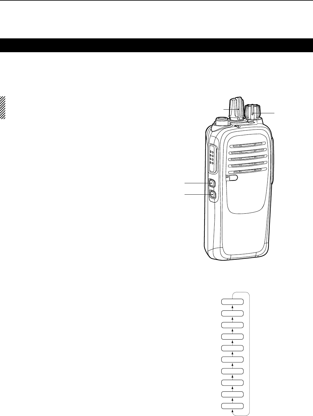
ROTARY SELECTOR
Rotate to select the preset memory channels.
VOLUME CONTROL [VOL]
Rotate to turn the power ON or OFF and to adjust the
audio level.
DEALER-ASSIGNABLE KEY [Emer]
A desired function can be preset by your dealer.
SPEAKER-MICROPHONE JACK
Connect an optional equipment.
NOTE: After turning OFF the transceiver, connect
or disconnect the optional equipment.
Jack cover
NOTE: Attach the jack cover when
optional equipment is not used.
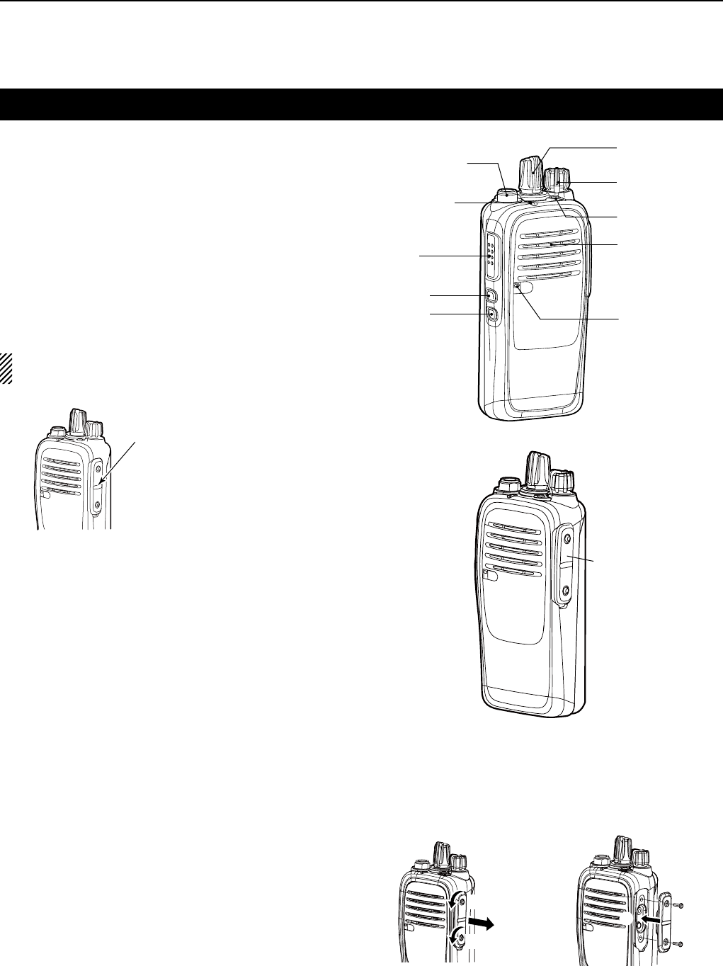
ROTARY
SELECTOR
VOLUME
CONTROL [VOL]
[Emer]
Speaker
[Lower]
[Upper]
PTT SWITCH
[PTT]
LED
INDICATOR
Microphone
ANTENNA
CONNECTOR
SPEAKER-
MICROPHONE
JACK
Front, top and side panels
DEALER-ASSIGNABLE KEYS [Upper] or [Lower]
Desired functions can be independently preset by
your dealer.
PTT SWITCH [PTT]
Hold down to transmit, release to receive.
LED INDICATOR (p. 1-3)
Lights red while transmitting. Â
Lights green while receiving a signal, or when the Â
squelch is open.
Lights or blinks orange when the matching 2-Tone Â
or 5-Tone is received, depending on the presetting.
You should charge the battery when the indicator Â
slowly blinks.
You must charge the battery when the indicator Â
blinks fast.
ANTENNA CONNECTOR
Connects the supplied antenna.
Detaching and attaching the jack cover
Attaching:
Attach the jack cover (q),
then tighten the screws (
w
).
Detaching:
Remove the screws (z),
then detach the jack cover (
x
).
x
q
w
w
z
z
Attaching:
Attach the jack cover (q),
then tighten the screws (
w
).
Detaching:
Remove the screws (z),
then detach the jack cover (
x
).
x
q
w
w
z
z
1PANEL DESCRIPTION
1-3
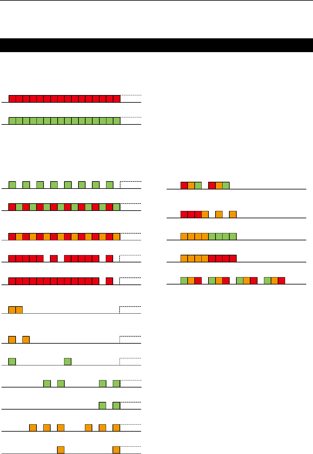
LED indicator
The LED indicator indicates the status of various
parameters of the transceiver as follows:
(Reference: R=Red, G=Green, O=Orange)
Cloning (reading or writing data)•
G G G G G G G G
Cloning Error (if cloning fails)•
R G R G R G R G R G R G R G R G
Inh, Blank CH, Unlocked •
(when you cannot use the channel)
R O R O R O R O R O R O R O R O
TX Low Battery 2 (while transmitting)•
R R R R R R R R R R R R
TX Low Battery 1 (while transmitting)•
R R R R R RR R R R R R R R
Call LED=ON •
(when receiving a matching 2-Tone or 5-Tone)
O O
Call LED=Blink •
(when receiving a matching 2-Tone or 5-Tone)
O O
Scanning•
G G
Low Battery 2 (You must charge the battery.)•
G G GG
Low Battery 1 (You should charge the battery.)•
G G
Calling•
O O O O O O
Audible•
O O
When turning ON the power•
R O G R O G
Lockout, TX Inh, TOT •
(when transmit is inhibited)
R R R O O O
Successful•
OO OO G GGG
Failed, Error•
O O OO RRR R
Emergency, Siren•
ROG ROG ROG ROG
Transmitting•
R R R R R R R RR R R R R R R R
Receiving•
G G G G G G G GG G G G G G G G
The following LED indicator patterns are repetitive.
One cycle is approximately two seconds.
The following LED indicator patterns light only once.

1PANEL DESCRIPTION
1-4
Programmable function keys
The following functions can be assigned to [Emer],
[Upper], and [Lower].
Consult your Icom dealer or system operator for
details concerning your transceiver’s presetting.
SCAN START/STOP
Push to start and cancel scanning operation.
When a scan started with the Power ON Scan or Auto
Scan function, push to cancel the scanning operation.
These scans resume after the specified time period,
depending on the Auto Reset setting.
PRIORITY A CHANNEL, PRIORITY B CHANNEL
Push to select the Priority A or Priority B channel.
PRIORITY A CHANNEL (REWRITE),
PRIORITY B CHANNEL (REWRITE)
Push to select the Priority A or Priority B channel. Â
Hold down [Prio A (Rewrite)] or [Prio B (Rewrite)] Â
for 1 second to assign the operating channel to
Priority A or Priority B channel, respectively.
MEMORY CHANNELS 1, 2, 3, 4
Push to directly select memory channel 1, 2, 3 or 4, if
preset.
MONI
// only for the LMR model //
Hold down to cancel the CTCSS (DTCS) or 2-Tone Â
mute.
The transceiver enters “Audible” mode.
Push to turn OFF the function. Â
MONI (Audi)
// only for the PMR model //
Hold down to cancel the CTCSS (DTCS) or 5-Tone Â
mute.
The transceiver enters “Audible” mode.
Push or hold down to activate one or two functions Â
if preset.
LOCK
Hold down this key for 1 second to turn the Key Lock
function ON or OFF.
The Key Lock function locks all programmable keys
except the followings:
[Moni], [Moni (Audi)], [Lock], [Emergency],
[Surveillance], [Siren], [Call], [Call A], [Call B], and
[Lone Worker].
LONE WORKER
Hold down to turn ON the Lone Worker Function. Â
Push to turn OFF the Function. Â
HIGH/LOW
Push to select the transmit output power temporarily
or permanently, depending on the presetting.
Beeps sound as described below and the beeps
indicate which output power you are selecting.
High (5 W for VHF, or 4 W for UHF): Three beeps
Low2 (2 W): Two beeps
Low1 (1 W): One beep
TALK AROUND
Hold down for 1 second to turn ON the Talk Around Â
function.
Push to turn OFF the Talk Around function. Â
The Talk Around function equalizes the transmit
frequency to the receive frequency, for transceiver-to-
transceiver communication.
WIDE/NARROW
(only for the analog mode operation)
Push to select toggle the channel bandwidth between
Wide, Middle*, and Narrow.
Beeps sound as described below and the beeps
indicate which channel bandwidth you are selecting.
Narrow: One beep
Middle*: Two beeps
Wide: Three beeps
* Only for the PMR model.
It is selectable depending on the presetting. Ask your
dealer for details.

1PANEL DESCRIPTION
1-5
DTMF AUTODIAL
Push to transmit the preset DTMF code.
CALL
Push to transmit a 2-Tone or 5-Tone in the operating
channel.
CALL A (CODE 1)/CALL B (CODE 2)
(only for the analog mode operation)
// only for the LMR model //
While in analog mode operation, push to transmit a
2-Tone code as station code, that is set in the channel
1 (Code A) or channel 2 (Code B).
CALL A (CODE 30)/CALL B (CODE 29)
(only for the analog mode operation)
// only for the PMR model //
While in analog mode operation, push to transmit a
5-Tone code as the station code, that is set in the
channel 30 (Code A) or channel 29 (Code B).
EMERGENCY
Hold down for the set time period* to turn ON the Â
Emergency function.
•ThecountdownfortheEmergencycalltransmission
starts. After the countdown, an Emergency call is
automatically transmitted once, or repeatedly*.
During the first countdown, hold down for the set Â
time period* to cancel the Emergency function.
*Depending on the presetting. Ask your dealer for details.
SURVEILLANCE
Hold down for 1 second to turn ON the Surveillance Â
function.
Push to turn OFF the Surveillance function. Â
When this function is turned ON, the beep is not
heard and the LED indicator does not light, even when
a signal is received, or a key is pushed.
SIREN
Hold down for 1 second to emit a siren sound. Â
•Thisfunctioncanbeusedforsituationsotherthanan
Emergency alert, such as a security alarm.
Turn OFF the transceiver power to stop the siren Â
sound.
ENCRYPTION
(only for the digital mode operation)
Hold down for 1 second to turn ON the Encryption Â
function.
Push to turn OFF the Encryption function. Â
ANNOUNCE
Push to turn the Channel Announce function ON or
OFF.
When this function is turned ON, the transceiver
announces the position of [ROTARY SELECTOR].
CALL ALERT
(only for the digital mode operation)
Hold down for 1 second to transmit a Call Alert.
STATUS
(only for the digital mode operation)
Hold down for 1 second to transmit a Status call.

2-1
Section 2BASIC OPERATION
Selecting a channel .................................................................2-2
Receiving and transmitting ....................................................2-3
Transmitting notes ................................................................2-3
Receiving a Stun, Kill, and Revive call ...............................2-3
Emergency call ........................................................................2-4
About other Emergency calls ................................................2-5
Lone Worker Emergency call ..............................................2-5
Man Down Emergency call ..................................................2-5
Motion Detection Emergency call .......................................2-5

2BASIC OPERATION
2-2
Selecting a channel
There are several types of channel selections.
Methods may differ, depending on the presetting.
Ask your dealer for details.
NON-ZONE TYPE:
To select the desired operating channel:
Rotate [ROTARY SELECTOR]. Â
Push one of [MR-CH 1] to [MR-CH 4]. Â
Push [Prio A], [Prio B], [Prio A (Rewrite)] or [Prio B Â
(Rewrite)].
AUTOMATIC SCAN TYPE:
Channel setting is not necessary for this scan
type. When turning ON the power, the transceiver
automatically starts scanning. Scanning stops when a
signal is received.

2BASIC OPERATION
2-3
Receiving and transmitting
CAUTION:
Attach an antenna before transmitting.
Transmitting without an antenna may damage the
transceiver.
Receiving:
Rotate [VOL] to turn ON the power.1)
Select a channel. (p. 2-2)2)
When receiving a call, adjust the audio output level 3)
to a comfortable listening level.
Transmitting:
Wait until the channel is clear to avoid interference. 1)
While holding down [PTT], speak at a normal voice
level.
Release [PTT] to receive.2)
IMPORTANT:
To maximize the readability of your signal:
1. After pushing [PTT], pause briefly before you
start speaking.
2. Hold the microphone 5 to 10 cm (2 to 4 inches)
from your mouth, then speak at a normal voice
level.
Transmitting notes
•Transmitinhibitfunction
The transceiver has several inhibit functions which
restrict transmission under the following conditions:
- The channel is busy.
However, depending on the presetting, you can
transmit when the call includes an unmatching (or
matching) CTCSS (DTCS) tone.
- The selected channel is a ‘receive only’ channel.
•Time-outtimer(TOT)
If continuous transmission exceeds the preset time-
out timer limit, transmission is cut off.
•Penaltytimer
The time-out timer cuts off transmission, further
transmission is inhibited for the preset penalty timer
period.
Receiving a Stun, Kill, and Revive call
The dispatcher can send a 2-Tone or 5-Tone that will
stun, kill or revive your transceiver.
When the Stun call is received, beeps sound, and you
cannot receive or transmit. Receiving a Revive call
or cloning the transceiver is necessary to operate the
transceiver again.
When the Kill call is received, beeps sound, and
the transceiver becomes unusable. Cloning the
transceiver is necessary to operate the transceiver
again, in this case.
NOTE:
These functions and operations may or may not be available or different, depending on the presetting.
Ask your dealer for preset information.

2BASIC OPERATION
2-4
When holding down [Emergency] for the set time
period, the transceiver enters the Emergency mode
then the countdown starts.
After the countdown, the transceiver transmits an
Emergency call once, or repeatedly, on the specified
Emergency channel. Countdown beeps sound for the
set timer period.
When no Emergency channel is specified, it transmits
the call on the previously selected channel.
If you want to cancel the Emergency call, turn OFF
the transceiver, or hold down [Emergency] for the set
time period again during the first countdown.
If your transceiver is set for the Silent operation, you
can transmit an Emergency call without beeps and
the LED indicator lighting.
NOTE:
Depending on the presetting, the following
functions are automatically activated. Ask your
dealer for details.
•AutoTXfunction
After an Emergency call transmission, the transceiver
transmits the audio from the microphone for the set
time period.
•AutoRXfunction
After the Emergency call transmission, the transceiver
stands by in the audible mode for the set time period.
Emergency call
NOTE:
This function and operations may or may not be available or different, depending on the presetting.
Ask your dealer for preset information.

2BASIC OPERATION
2-5
About other Emergency calls
Lone Worker Emergency call
When the Lone Worker function is ON, the transceiver
enters the Emergency mode then the countdown for
the Emergency call transmission starts when either/
or:
1. No operation occurs for the set time period.
2. The acceleration sensor detects a lower
acceleration than the set value for the set time
period.
After a set time period has passed, an Emergency call
is automatically transmitted once, or repeatedly.
If the user pushes any key during the first countdown,
the transceiver exits the Emergency mode, and the
Emergency call is cancelled.
You can also cancel the Emergency call by turning
OFF the transceiver.
To turn ON the Lone Worker function, see page 1-4.
Man Down Emergency call
When the transceiver leans past the preset angle for a
set time period, the transceiver enters the Emergency
mode, and then a countdown starts.
After a set time period has passed, an Emergency call
is automatically transmitted once, or repeatedly.
If the transceiver is placed again within the preset
angle, during the first countdown, the transceiver
exits the Emergency mode, and the Emergency call is
cancelled.
You can also cancel the Emergency call by turning
OFF the transceiver.
Motion Detection Emergency call
When the acceleration sensor keeps detecting a
higher acceleration than the preset value for the set
time period, the transceiver enters the Emergency
mode then the countdown starts.
After the set time period has passed, an Emergency
call is automatically transmitted once, or repeatedly.
Countdown beeps sound for the set time period.
If the user holds down [Emergency] for the set time
period during the first countdown, the Emergency call
is canceled.
You can also cancel the Emergency call by turning
OFF the transceiver.
NOTE:
These functions and operations may or may not be available or different, depending on the presetting.
Ask your dealer for preset information.

3-1
Section 3NXDN™ OPERATION
NXDN™ operation ...................................................................3-2
Conventional mode ...............................................................3-2
Trunking mode ......................................................................3-2
Receiving a call .......................................................................3-3
Receiving a Call Alert ...........................................................3-3
Receiving a Stun, Kill, and Revive call ...............................3-3
Receiving a Remote Monitor or Radio Check call .............3-3
Receiving a Status call .........................................................3-3
Transmitting a call ...................................................................3-4
Transmitting a Call Alert ......................................................3-4
Transmitting an Emergency call .........................................3-4
Transmitting a Status call ....................................................3-4
About other Emergency calls ................................................3-5
Lone Worker Emergency call ..............................................3-5
Man Down Emergency call ..................................................3-5
Motion Detection Emergency call .......................................3-5
Encryption function ................................................................3-6

3NXDN™ OPERATION
3-2
NXDN™ operation
The transceiver provides Icom Digital Advanced
System (IDAS™) that meets the 6.25 kHz emission
mask requirements for narrow banding, and increases
efficiency of channel allocation and use of spectrum
using the NXDN™ common air interface.
NOTE:
During the NXDN™ system operation, BIIS 1200
and MDC 1200 system operations are not usable.
You can use a preset operation type in a zone.
Ask your dealer for details.
Conventional mode
The Conventional system enables normal digital
mode channel management by manually selecting a
channel.
Trunking mode
The Trunk system enables further effective channel
management by sharing a minimum number of
channels with a large number of users.
NOTE:
While in the Trunking mode, you can receive and
transmit digital calls in the same way as in the
Conventional mode.

3NXDN™ OPERATION
3-3
Receiving a call
Receiving a Call Alert
When a Call Alert is received: Â
•Thetransceiverwillautomaticallytransmitthe
acknowledgement.
•TheLEDindicatorblinksorange.
•Release[PTT]toreceivearesponse.
Hold down [PTT], then speak into the microphone.1)
Release [PTT] to receive a response.2)
Receiving a Stun, Kill, and Revive call
If an individual call with Stun or Kill command is
received, the transceiver will automatically transmit
the acknowledgement, and then you cannot receive
or transmit.
When a Stun command is received: Â
•Youcannotreceive,transmit,orchangethechannel.
•ReceivingaRevivecallorcloningthetransceiveris
necessary to operate the transceiver again.
When a Kill command is received: Â
•Thetransceiverbecomesunusable.
•TheLEDindicatoralternatelyblinksredandorange.
•Cloningthetransceiverisnecessarytousethe
transceiver again.
Receiving a Remote Monitor or Radio
Check call
When a Remote Monitor call is received: Â
•Thetransceiverwillautomaticallytransmitthe
acknowledgement
•Thenittransmitsthemicrophoneaudioforthetimeset
at the caller station.
When a Radio Check call is received: Â
•Thetransceiverwillautomaticallytransmitthe
acknowledgement.
Receiving a Status call
When a Status call is received: Â
•Thetransceiverwillautomaticallytransmitthe
acknowledgement.
NOTE:
These functions and operations may or may not be available or different, depending on the presetting.
Ask your dealer for preset information.

3NXDN™ OPERATION
3-4
Transmitting a call
Transmitting a Call Alert
Hold down [Call Alert]. Â
Transmitting an Emergency call
When holding down [Emergency] for the set time
period, the transceiver enters the Emergency mode
then the countdown starts.
After the countdown, the transceiver transmits
an Emergency call (digital command) once, or
repeatedly, on the specified Emergency channel.
Countdown beeps sound for the set time period.
When no Emergency channel is specified, it transmits
the call on the previously selected channel.
Individual or Talkgroup call types of Emergency calls
can be preset. If the call type is not preset, a default
or selected call type is used.
If you want to cancel the Emergency call, turn OFF
the transceiver, or hold down [Emergency] for the set
time period again during the first countdown.
If your transceiver is set for Silent operation, you can
transmit an Emergency call without beeps and the
LED indicator lighting.
The transceiver can also be set to keep the
microphone open during an Emergency call, allowing
other persons to monitor the situation. Ask your dealer
for details.
Transmitting a Status call
A Status call can be transmitted by pushing [Status]. Â
Rotate [ROTARY SELECTOR] to select a desired 1)
Status.
Hold down [Status] to transmit a Status call.2)
A Status call can be automatically transmitted when Â
the transceiver is turned ON or OFF.
A Status call can be automatically transmitted after Â
releasing [PTT].
NOTE:
These functions and operations may or may not be available or different, depending on the presetting.
Ask your dealer for preset information.

3NXDN™ OPERATION
3-5
About other Emergency calls
Lone Worker Emergency call
When the Lone Worker function is ON, the transceiver
enters the Emergency mode then the countdown for
the Emergency call transmission starts when either/
or:
1. No operation occurs for the set time period.
2. The acceleration sensor detects a lower
acceleration than the set value for the set time
period.
After a set time period has passed, an Emergency call
is automatically transmitted once, or repeatedly.
If the user pushes any key during the first countdown,
the transceiver exits the Emergency mode, and the
Emergency call is cancelled.
You can also cancel the Emergency call by turning
OFF the transceiver.
To turn ON the Lone Worker function, see page 1-4.
Man Down Emergency call
When the transceiver leans past the preset angle for a
set time period, the transceiver enters the Emergency
mode, and then a countdown starts.
After a set time period has passed, an Emergency call
is automatically transmitted once, or repeatedly.
If the transceiver is placed again within the preset
angle, during the first countdown, the transceiver
exits the Emergency mode, and the Emergency call is
cancelled.
You can also cancel the Emergency call by turning
OFF the transceiver.
Motion Detection Emergency call
When the acceleration sensor keeps detecting a
higher acceleration than the preset value for the set
time period, the transceiver enters the Emergency
mode then the countdown starts.
After the set time period has passed, an Emergency
call is automatically transmitted once, or repeatedly.
Countdown beeps sound for the set time period.
If the user holds down [Emergency] for the set time
period during the first countdown, the Emergency call
is canceled.
You can also cancel the Emergency call by turning
OFF the transceiver.
NOTE:
These functions and operations may or may not be available or different, depending on the presetting.
Ask your dealer for preset information.

3NXDN™ OPERATION
3-6
Encryption function
The Encryption function enables voice scrambling,
which provides a private digital communication
between stations.
Hold down [Encryption] for 1 second to turn ON the 1)
Encryption function.
Push [Encryption] to turn OFF the Encryption 2)
function.
NOTE:
This function and operations may or may not be available or different, depending on the presetting.
Ask your dealer for preset information.

4-1
Section 4MDC 1200 SYSTEM OPERATION
MDC 1200 system operation ..................................................4-2
Receiving a call .......................................................................4-3
Receiving a PTT ID ...............................................................4-3
Receiving an Emergency call ..............................................4-3
Receiving a Stun or Revive call ...........................................4-3
Transmitting a call ...................................................................4-4
Transmitting a PTT ID ...........................................................4-4
Transmitting an Emergency call .........................................4-4

4MDC 1200 SYSTEM OPERATION
4-2
MDC 1200 system operation
The MDC 1200 signaling system enhances your
transceiver’s capabilities. You can receive or transmit
PTT ID and Emergency calls. You can also receive
Radio Check, Stun, and Revive calls.
An additional feature of the MDC 1200 system
included in Icom transceivers is called aliasing. Each
transceiver on the system has a unique ID number.
Aliasing is a substitute for this ID number and you can
set a ringer for each station ID. When you receive a
call from the specific transceiver, you can distinguish
it by its ringer type.
NOTE:
The MDC 1200 system operation may not be
available, depending on the presetting. Ask your
dealer for preset information.

4MDC 1200 SYSTEM OPERATION
4-3
Receiving a call
Receiving a PTT ID
When a PTT ID is received:1)
•Beepssound.
Hold down [PTT] and speak into the microphone.2)
Release [PTT] to receive a response.3)
Receiving an Emergency call
When an Emergency call is received:1)
•Beepssound.
Turn power OFF or change the channel to stop the 2)
beep.
Receiving a Stun or Revive call
If a Stun call is received that matches your station ID,
you can not receive or transmit. If a Revive call that
matches your station ID is received, the transceiver
will be revived.
NOTE:
These functions and operations may or may not be available or different, depending on the presetting.
Ask your dealer for preset information.

4MDC 1200 SYSTEM OPERATION
4-4
Transmitting a call
Transmitting a PTT ID
Push [PTT] to make a call.1)
Beeps sound, depending on the presetting.2)
Your station ID will be transmitted when you push 3)
[PTT] (at the beginning of transmission) or release
it (at the end of transmission), depending on the
presetting.
Transmitting an Emergency call
When holding down [Emergency] for the set time
period, the transceiver enters the Emergency mode
then the countdown starts.
After the countdown, the transceiver transmits an
Emergency call once, or repeatedly, on the specified
Emergency channel. Countdown beeps sound for the
set time period.
When no Emergency channel is specified, it transmits
the call on the previously selected channel.
If you want to cancel the Emergency call, turn OFF
the transceiver, or hold down [Emergency] for the set
time period again during the first countdown.
If your transceiver is set for Silent operation, you can
transmit an Emergency call without beeps and the
LED indicator lighting.
The transceiver can also be set to keep the
microphone open during an Emergency call, allowing
other persons to monitor the situation. Ask your dealer
for details.
NOTE:
These functions and operations may or may not be available or different, depending on the presetting.
Ask your dealer for preset information.

5-1
Section 5USER SETTINGS
Setting the Beep function ......................................................5-2
Setting the Beep level .............................................................5-3
Setting the Ringer level ..........................................................5-4
Setting the microphone gain ..................................................5-5
Setting the squelch level ........................................................5-6
Setting the VOX function ........................................................5-7
Setting the VOX gain ...............................................................5-8
5USER SETTINGS
5-2
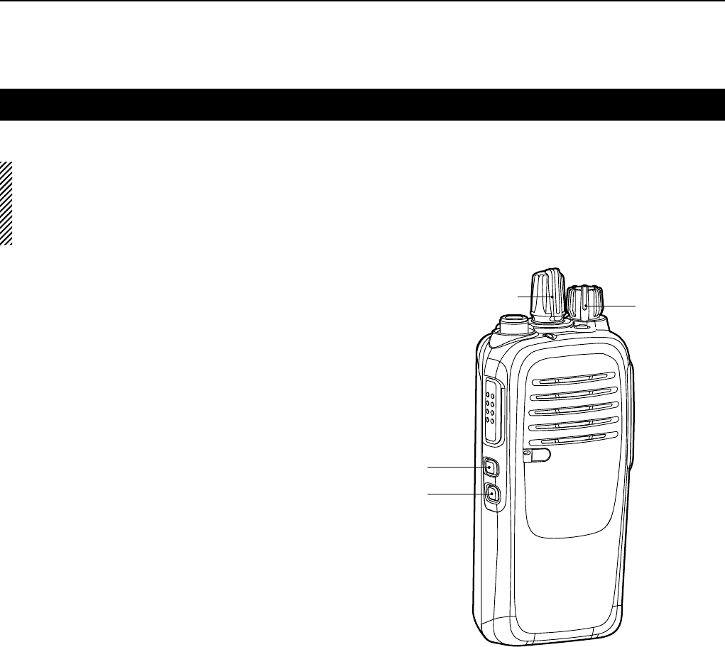
Setting the Beep function
The Beep function can be turned ON or OFF.
NOTE:
You should turn ON the Beep function when you
set the Beep level, the Ringer level, the microphone
gain, the VOX function, the VOX gain and the
squelch level.
Rotate [VOL] to turn the transceiver power OFF.1)
Set [ROTARY SELECTOR] to any channel other 2)
than Channel 16.
While holding down [Lower], rotate [VOL] to turn 3)
ON the power to enter the Beep level adjustment
mode.
Push [Lower] to turn the Beep function ON or OFF.4)
•Whenabeepsoundsafterpushing[Lower],the
Beep function is ON. When no beep sounds after
pushing [Lower], the Beep function is OFF.
•Thetransceiverstoresthesettingeverytimeyou
change it.
•Ifdesired,push[Upper]toadjusttheBeeplevel.See
page 5-4 for details.
Rotate [VOL] to turn OFF the power to exit the 5)
Beep level adjustment mode.
[ROTARY SELECTOR] [VOL]
[Upper]
[Lower]
5USER SETTINGS
5-3
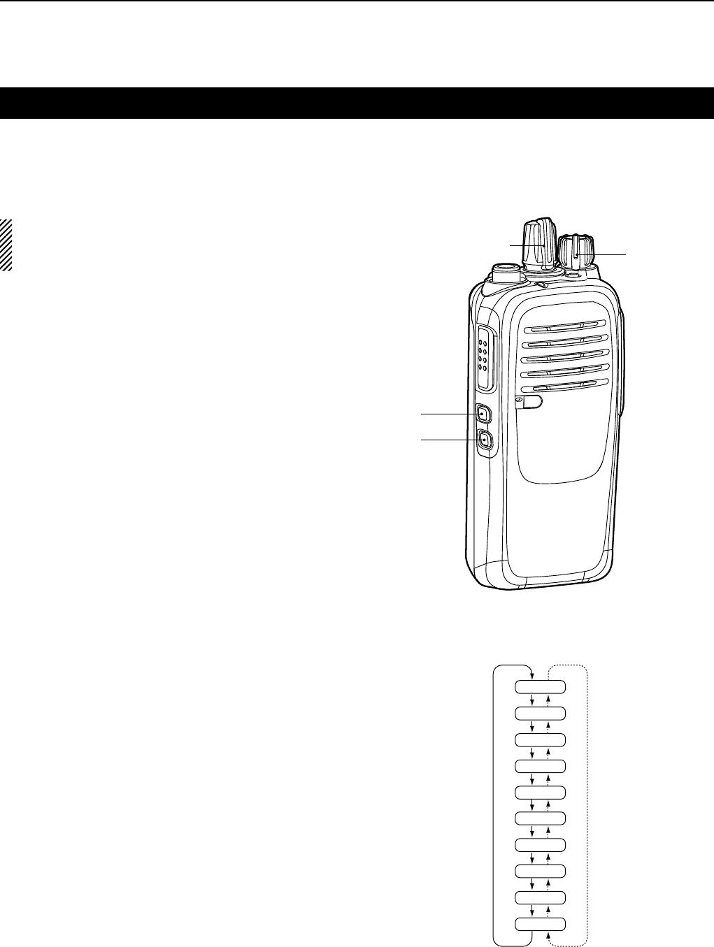
Setting the Beep level
The Beep level is adjustable between 1 and 5, or
1 (linked) and 5 (linked). When a Linked option is
selected, the beep audio level is adjustable by rotating
[VOL].
Rotate [VOL] to turn OFF the transceiver.1)
Set [ROTARY SELECTOR] to any channel other 2)
than Channel 16.
While holding down [Lower], rotate [VOL] to turn 3)
ON the power and enter the Beep level adjustment
mode.
Push [Upper] to change the Beep level.4)
•Repeatedlypushing[Upper]firstselects1(lowest)to
5 (highest), and then selects the lowest linked level, 1
(Linked) to the highest, 5 (Linked). Repeatedly pushing
[Upper] repeats the cycle. See the illustration on the
right.
•Theadjustablerangeis1to5or1(Linked)to5
(Linked).
•Abeepsoundseverytimeyoupush[Upper].Therefore,
you can determine the current level setting by the
increasing loudness of the beep that sounds.
•Todetermineifyouhaveselectedalinkedlevel,set
[VOL] to minimum, then push [Upper] repeatedly,
listening for the loudest beep (level 5). Pushing [Upper]
once after the loudest beep will select 1 (Linked).
Repeatedly push [Upper] to select the desired linked
level.
Rotate [VOL] to turn OFF the power to exit the 5)
Beep level adjustment mode.
[ROTARY SELECTOR] [VOL]
[Upper]
[Lower]
2
5
4
3
1
5 (Linked)
4 (Linked)
3 (Linked)
2 (Linked)
1 (Linked)
Pushing
[Upper]
NOTE:
You should turn ON the Beep function (p. 5-2)
before you start setting the Beep level.
5USER SETTINGS
5-4
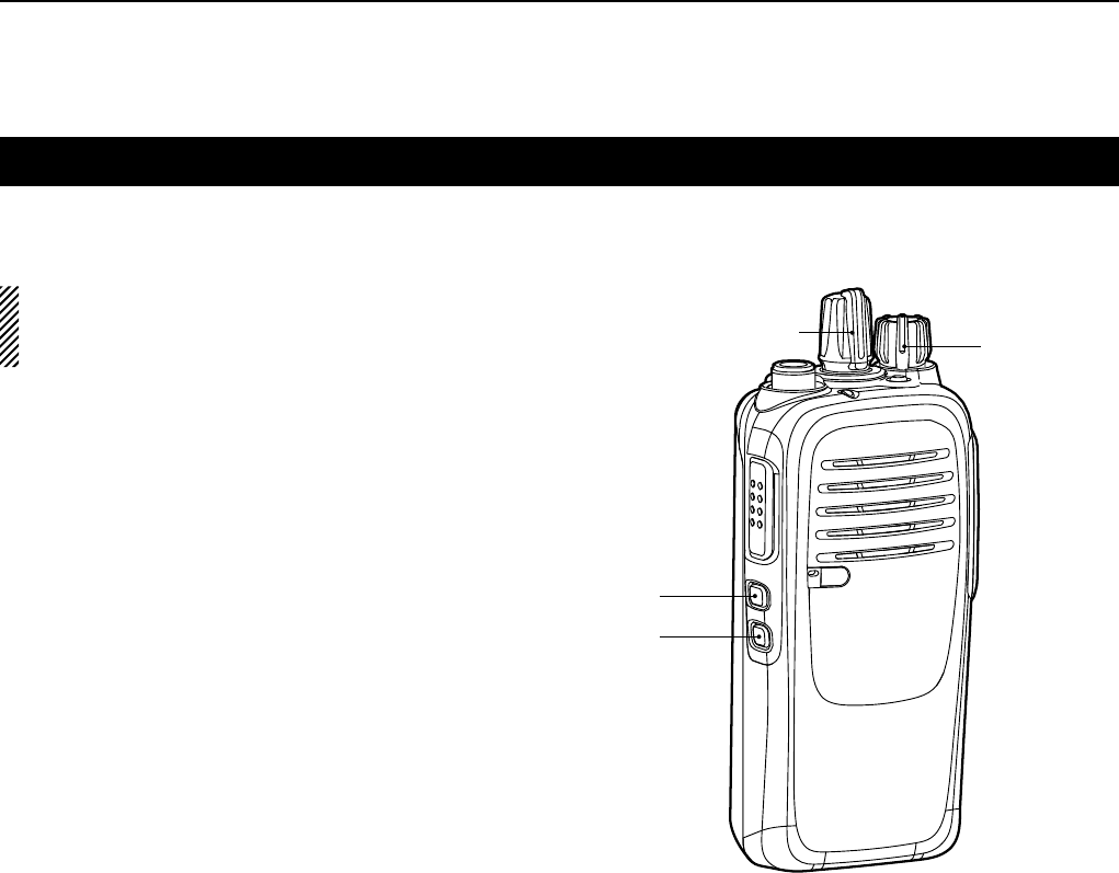
Setting the Ringer level
The Ringer level can be adjusted between 1 and 5,
or 1 (Linked) and 5 (Linked). When a Linked option
is selected, the ringer audio level is adjustable by
rotating [VOL].
Rotate [VOL] to turn OFF the transceiver power.1)
Set [ROTARY SELECTOR] to Channel 16.2)
While holding down [Lower], rotate [VOL] to 3)
turn ON the power and enter the Ringer level
adjustment mode.
Push [Upper] to increase, or push [Lower] to 4)
decrease the Ringer level.
•Repeatedlypushing[Upper]firstselects1(lowest)to
5 (highest), and then selects the lowest linked level, 1
(Linked) to the highest, 5 (Linked). Repeatedly pushing
[Upper] or [Lower] repeats the cycle. See the illustration
on the right.
•Theadjustablerangeis1to5or1(Linked)to5
(Linked).
•Abeepsoundsafterpushing[Upper].Therefore,
you can determine the current level setting by the
increasing loudness of the beep that sounds.
•Todetermineifyouhaveselectedalinkedlevel,set
[VOL] to minimum, then push [Upper] up to 10 times,
listening for the loudest beep (level 5). Pushing [Upper]
once after the loudest beep will select 1 (Linked).
Repeatedly push [Upper] or [Lower] to select the
desired linked level.
Rotate [VOL] to turn OFF the power to exit the 5)
Ringer level adjustment mode.
[ROTARY SELECTOR] [VOL]
[Upper]
[Lower]
2
5
4
3
1
5 (Linked)
4 (Linked)
3 (Linked)
2 (Linked)
1 (Linked)
Pushing
[Upper]
Pushing
[Lower]
NOTE:
You should turn ON the Beep function (p. 5-2)
before you start setting the Ringer level.

5USER SETTINGS
5-5
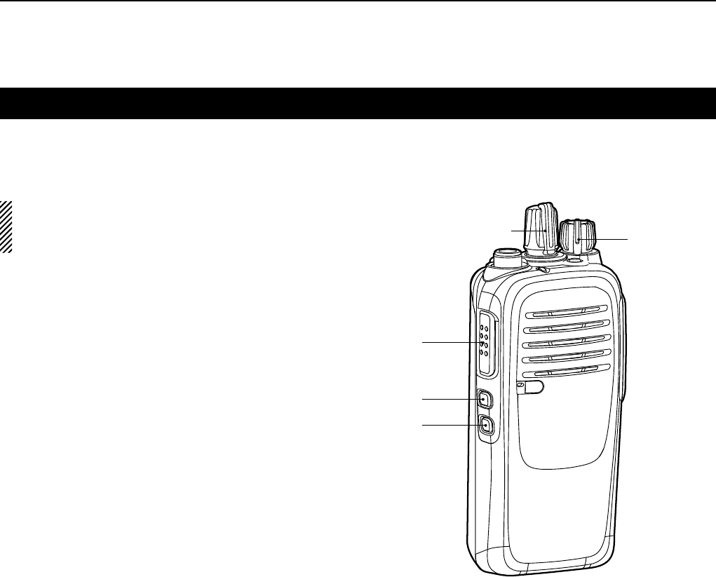
Setting the microphone gain
Adjust the microphone gain.
Higher values make the microphone more sensitive to
the user voice.
Rotate [VOL] to turn OFF the transceiver power.1)
Set [ROTARY SELECTOR] to Channel 16.2)
While holding down [Upper], rotate [VOL] to turn 3)
ON the power and enter the microphone gain
adjustment mode.
Push [Upper] to increase, or push [Lower] to 4)
decrease the microphone gain.
•Theadjustablerangeis1(minimum)to4(maximum).
•Abeepsoundsafterpushing[Upper]or[Lower].An
error beep sounds if you try to exceed the adjustable
range.
Rotate [VOL] to turn OFF the power to exit the 5)
microphone gain adjustment mode.
[ROTARY SELECTOR] [VOL]
[Upper]
[Lower]
NOTE:
You should turn ON the Beep function (p. 5-2)
before you start setting the microphone gain.
5USER SETTINGS
5-6
Setting the squelch level
The squelch circuit mutes the received audio signal,
depending on the signal strength.
Rotate [VOL] to turn OFF the transceiver power.1)
Set [ROTARY SELECTOR] to any channel other 2)
than Channel 16.
While holding down [Upper], rotate [VOL] to 3)
turn ON the power and enter the squelch level
adjustment mode.
Push [Upper] to increase the squelch level (tight 4)
squelch), or push [Lower] to decrease the squelch
level (loose squelch).
•Theadjustablerangeis0(loosesquelch)to9(tight
squelch).
•Abeepsoundsafterpushing[Upper]or[Lower].An
error beep sounds if you try to exceed the adjustable
range.
Rotate [VOL] to turn OFF the power to exit the 5)
squelch level adjustment mode.
[ROTARY SELECTOR] [VOL]
[Upper]
[Lower]
NOTE:
You should turn ON the Beep function (p. 5-2)
before you start setting the squelch level.
5USER SETTINGS
5-7
Setting the VOX function
The VOX function can be turned ON or OFF. The VOX
function automatically switches between receive and
transmit during voice operation.
Rotate [VOL] to turn OFF the transceiver power.1)
Set [ROTARY SELECTOR] to any channel other 2)
than Channel 16.
While holding down [PTT] and [Upper], rotate 3)
[VOL] to turn ON the power, to turn the VOX
function ON or OFF.
•WhentheVOXfunctionisON,abeepsounds.
•WhentheVOXfunctionisOFF,twobeepssound.
Rotate [VOL] to turn OFF the power, then turn ON 4)
again to restart the normal operation.
NOTE:
You should turn ON the Beep function (p. 5-2)
before you start setting the VOX function.
[ROTARY SELECTOR] [VOL]
[Upper]
[PTT]
[Lower]

5USER SETTINGS
5-8
Setting the VOX gain
Adjust the VOX gain.
Higher values make the VOX function more sensitive
to the user voice.
Rotate [VOL] to turn OFF the transceiver power.1)
Set [ROTARY SELECTOR] to Channel 16.2)
While holding down [PTT] and [Upper], rotate 3)
[VOL] to turn ON the power and enter the VOX gain
adjustment mode.
Push [Upper] to increase, or push [Lower] to 4)
decrease the microphone gain.
•Theadjustablerangeis1(minimum)to10(maximum).
•Abeepsoundsafterpushing[Upper]or[Lower].An
error beep sounds if you try to exceed the adjustable
range.
Rotate [VOL] to turn OFF the power to exit the VOX 5)
gain adjustment mode.
[ROTARY SELECTOR] [VOL]
[Upper]
[PTT]
[Lower]
NOTE:
You should turn ON the Beep function (p. 5-2)
before you start setting the VOX gain.

1-1-32 Kamiminami, Hirano-ku, Osaka 547-0003, Japan
A-7206-5EX
© 2015 Icom Inc.