ICOM orporated IC-746PRO Amateur HF \ VHF Scanning Transceiver User Manual 746PRO INSTRUCTION MANUAL EN pd
ICOM Incorporated Amateur HF \ VHF Scanning Transceiver 746PRO INSTRUCTION MANUAL EN pd
Contents
- 1. Manual Part 1
- 2. Manual Part 2
Manual Part 2
![547FUNCTIONS FOR RECEIVE■Simple band scope The band scope function allows you to visually checksignal condition around a specified frequency. The IC-746PRO’s band scope function can be used in any op-erating mode and frequency band.The band scope measures receive signal conditionsover a specified range on either side of a selected fre-quency in either VFO or memory modes.qRotate the tuning dial to tune a frequency.wWhile M1 is selected, push [F5 SCP] to select theband scope menu.•Starts sweeping automatically with the previously se-lected sweeping step. •During sweep, received signals cannot be heard.ePush [F5 STEP] several times to select the desiredsweep step.rPush [F1] to start sweeping, then stop automaticallyafter sweeping.•Push [F1] for 1 sec. to start continuous sweeping. In thiscase, it is necessary to push [F1] to stop sweeping.•During sweep operation “” appears and receivedsignals cannot be heard.•If there is a lot of signal noise, turn the preamp OFF andthe attenuator ON to reduce the signal input level andimprove the readability of the band scope.tWhen rotating the tuning dial and finding a signalyou wish to communicate on, simple communicatenormally.•If you want to return to the previous frequency (beforerotating the tuning dial), push [F3] for 1 sec.•If the selected frequency is set outside of the sweepedrange, flashes.yWhile receiving, if you want to update the band con-ditions, repeat steps eand ras above.“ ” or “ ”0.5kSTEPSweep indicatorBand scope indicatorFrequency indicator markSweep step indicatorINDICATORSweep Band scope in-dicatorFrequency indicator markSweep stepDESCRIPTIONWhile the band scope is “sweeping,” “” appears; while stopped “” appears. Receivedaudio is not emitted from the speaker while the band scope is “sweeping.”Indicates the relative strength of signals and their location in relation to the center (displayed)frequency. Signal strength is relative to the S-meter level, S1 to S9, with each vertical dot in theband scope indicator equal to one segment of the S-meter. Signal activity is measured ±30steps from the center frequency with each step equal to the selected sweep step.After a sweep, indicates the relative position of the selected frequency. When the selected fre-quency is outside of the sweep range, indicator flashes. After changing the fre-quency, push [F3] for 1 sec. to automatically return to the center frequency.Indicates the selected sweep step. 0.5, 1, 2, 5, 10, 20 and 25 kHz are selectable. Each dot ofthe band scope indication is approx. equal to the selected sweep step.“ ” or “ ”F 1 F 2 F 3 F 4 F 5F 1 F 2 F 3 F 4 F 5Sweep step selectionSweep start/stopO.5kSTEPO.5kSTEPSweep indicator](https://usermanual.wiki/ICOM-orporated/IC-746PRO.Manual-Part-2/User-Guide-183823-Page-1.png)
![485FUNCTIONS FOR RECEIVE■Preamp/AttenuatorThe preamp amplifies received signals in the front endcircuit to improve the S/N ratio and sensitivity. Set thisto preamp 1 or preamp 2 when receiving weak signals.The attenuator prevents a desired signal from distor-tion when very strong signals are near the desired fre-quency or when very storing electric fields, such asfrom broadcasting station, are near your location.These can both set independently for each band.➥Push [P.AMP/ATT] several times to set the preampOFF, preamp 1 ON or preamp 2 ON.•When the preamp is ON, either “P.AMP 1” or“P.AMP 2” appears in the function display.•When operating on the 144 MHz band, the preamp canonly be set to ON or OFF only— there is no preamp 1and preamp 2.➥Push [P.AMP/ATT] for 1 sec. to set the attenuator ON.•“ATT” appears ni the display when the function is set ON.•Push [P.AMP/ATT] momentarily to set the attenuator OFF.■RIT functionThe RIT (Receive Increment Tuning) function compen-sates for off-frequencies of the communicating station.The function shifts the receive frequency up to±9.99 kHz in 10 Hz steps without moving the transmitfrequency.•See #0 on p. 4 for function description.qPush [RIT] to turn the RIT function ON and OFF.•“RIT” and the shifting frequency appear when the func-tion is ON.wRotate the [RIT/∂TX] control.•Push [CLEAR] for 1 sec. to reset the RIT frequency.•Push [CLEAR] momentarily to reset the RIT frequencywhen the quick RIT/∂TX clear function is ON. (p. 85)•Push [RIT] for 1 sec. to add the shift frequency to the op-erating frequency.DRIT monitor functionWhen the RIT function is ON, pushing and holding[XFC] allows you to monitor the operating frequencydirectly (RIT is temporarily cancelled).[P.AMP/ATT]PushP.AMP/ATTPushP.AMP/ATTPushP.AMP/ATTPush for 1sec.P.AMP/ATTPushP.AMP/ATTRegular preamp, the most effective for 1.8 to21 MHz bands without IMD corruption.High-gain preamp, the most effective for 24to 50 MHz bands.Preamp activates for the VHF band (144 to146 MHz range; 108 to 174 for the USA version).[RIT][CLEAR][RIT/∂TX] controlappearRegarding the use of the “P.AMP 2”The “P.AMP 2” is a high gain receive amplifier. When the“P.AMP 2” is used during times of strong electric fields, dis-tortion sometimes results. In such cases, use the trans-ceiver with the “P.AMP 1” or “P.AMP OFF” setting.The “P.AMP 2” is most effective when:•Used on bands above 24 MHz and when electric fields areweak.•Receive sensitivity is insufficient during low gain, or whileusing a narrow band antenna (such as small loop, a Bever-age antenna or a short Yagi antenna, etc.) is used.](https://usermanual.wiki/ICOM-orporated/IC-746PRO.Manual-Part-2/User-Guide-183823-Page-2.png)
![495FUNCTIONS FOR RECEIVE ■AGC functionThe AGC (auto gain control) controls receiver gain toproduce a constant audio output level even when thereceived signal strength is varied by fading, etc.The transceiver has 3 AGC characteristics (time con-stant; fast, mid, slow) for non-FM mode. The FM mode AGC time constant is fixed as ‘FAST’(0.1 sec.) and AGC time constant cannot be se-lected.DAGC speed selectionqSelect non-FM mode.wWhile M1 is selected, push [F1 AGC] several timesto select AGC F, AGC M, AGC Sor AGC OFF.“AGC OFF” appears when AGC time constant OFFis set with one of FAST, MID or SLOW setting inAGC set mode.DSetting the AGC time constantqSelect the desired mode except FM mode.wWhile M1 is selected, push [F1 AGC] for 1 sec. toenter AGC set mode.ePush one of [F2FAST], [F3MID] or [F4SLOW] to se-lect the desired AGC speed to be set.•Underline appears below the time constant indication.rRotate the tuning dial to set the desired time con-stant.•AGC time constant can be set between 0.1 to 8.0 sec.(depends on mode) or turned OFF.•Push [F2FAST], [F3MID] or [F4SLOW] for 1 sec. to se-lect a default value for each fast, mid. and slow, respec-tively.tSelect another mode except FM. Repeat steps eand rif desired.yPush [MENU] to exit the AGC set mode.•Selectable AGC time constant (unit: sec.)Mode Default Selectable AGC time constant0.3 (FAST) OFF, 0.1, 0.2, 0.3, 0.5, 0.8, 1.2, 1.6SSB 2.0 (MID) 2.0, 2.5, 3.0, 4.0, 5.0, 6.06.0 (SLOW)0.1 (FAST) OFF, 0.1, 0.2, 0.3, 0.5, 0.8, 1.2, 1.6CW 0.5 (MID) 2.0, 2.5, 3.0, 4.0, 5.0, 6.01.2 (SLOW)0.1 (FAST) OFF, 0.1, 0.2, 0.3, 0.5, 0.8, 1.2, 1.6RTTY 0.5 (MID) 2.0, 2.5, 3.0, 4.0, 5.0, 6.01.2 (SLOW)3.0 (FAST) OFF, 0.3, 0.5, 0.8, 1.2, 1.6, 2.0, 2.5AM 5.0 (MID) 3.0, 4.0, 5.0, 6.0, 7.0, 8.07.0 (SLOW)FM 0.1 (FAST) Fixed[F1 AGC] Mode switches: Medium AGC speed: Slow AGC speed: Fast AGC speed: AGC does not activatedF 1F 2F 3F 4F 5F 1F 2 F 3F 4F 5F 1 F 2 F 3 F 4 F 5AGC DUP CMP TBW SCPPush [F1] for 1 sec.Selected modeAppears under the selected AGC speed’s time constant indication.Push [F2] for 1 sec. to select the default value in this case.• When AGC fast is selected](https://usermanual.wiki/ICOM-orporated/IC-746PRO.Manual-Part-2/User-Guide-183823-Page-3.png)
![505FUNCTIONS FOR RECEIVE ■IF filter selectionThe transceiver has 3 passband width IF filters foreach mode. For SSB and CW modes, the passband width can beset within 50 to 3600 Hz in 50 or 100 Hz steps. A totalof 41 passband widths are available. For RTTY mode, the passband width can be set within50 to 2700 Hz in 50 or 100 Hz steps. A total of 32passband widths are available.For AM and FM modes, the passband width is fixedand 3 passband widths are available independently.The filter selection is automatically memorized ineach mode.The PBT shift frequencies are automatically memo-rized in each filter.DIF filter selectionqSelect the desired mode.wFor RTTY mode, turn OFF the RTTY filter.ePush [FILTER] several times to select the IF filter1, 2or 3.•The selected passband width and filter number is dis-played in the LCD.By pushing [PBTC] indicate the set filter passbandwidth, “B,” and shifting value “S.”DFilter passband width setting (SSB, CW and RTTY mode only)qSelect SSB, CW or RTTY mode.•Passband widths for AM and FM modes are fixed andcannot be set.wFor RTTY mode, turn OFF the RTTY filter.ePush [FILTER] for 1 sec. to enter filter set mode.rPush [FILTER] several times to select the desiredIF filter number.tWhile pushing [F1 BW], rotate the tuning dial to setthe desired passband width.•In SSB and CW modes, the passband width can be setwithin the following range.50 to 500 Hz 50 Hz steps600 to 3600 Hz 100 Hz steps•In RTTY mode, the passband width can be set within thefollowing range.50 to 500 Hz 50 Hz steps600 to 2700 Hz 100 Hz steps•Push [F-3] for 1 sec. to select the default value.yRepeat steps rto tif desired.uPush [MENU] to exit the filter set mode.The PBT shift frequencies are cleared when thepassband width is changed.This filter set mode screen graphically displays thePBT shift frequencies and CW pitch operations.AGC DUP CMP TBW SCP[FILTER]The selected filter width is indicatedfor approx. 1 sec. when [FILTER] ispushed. Filter selectionBW• Filter set mode indicationShows the selected filter and passband width.BW• Indication while settingWhile pushing [F1 BW], rotate the tuning dial to setpassband width.Reverses Appears](https://usermanual.wiki/ICOM-orporated/IC-746PRO.Manual-Part-2/User-Guide-183823-Page-4.png)
![515FUNCTIONS FOR RECEIVE [NB]NB Level5O%Shows noise blanker level“NB” appears while noise blanker is activated.■IF (DSP) filter shapeThe type of IF (DSP) filter shape for each SSB andCW can be selected independently from soft andsharp.qPush [SSB] or [CW/RTTY] to select SSB, CW orRTTY mode.wSelect the filter set mode.•Push [FILTER] for 1 sec.•Operating mode can be selected in this step.ePush [FILTER] several times to select the desiredIF filter.rPush the [F5] to select the filter shape from “SOFT”and “SHARP.”tPush [MENU] to exit the set mode.■Noise blankerThe noise blanker eliminates pulse-type noise such asfrom car ignitions. The noise blanker is not availablefor FM mode.qPush [NB] to turn the noise blanker ON.•[NB] indicator appears.wPush [NB] for 1 sec. to enter the NB level set mode.eRotate the tuning dial to adjust the noise blankerlevel.•Noise blanker level is indicated with bar meter and digitin ‘%.’rPush [NB] to exit the noise blanker set mode.tPush [NB] to turn the noise blanker OFF.•[NB] indicator disappears.When using the noise blanker, received signals maybe distorted if they are excessively strong.■Meter peak hold functionThe S-meter shows the peak level holding function.Peak level of receiving signal strength is indicated for0.5 sec. (approx.). This function can be deactivated inthe set mode if desired. (p. 81)BWBWPush [F5]Meter Peak Hold9ONShows peak level for approx. 0.5 sec.](https://usermanual.wiki/ICOM-orporated/IC-746PRO.Manual-Part-2/User-Guide-183823-Page-5.png)
![525FUNCTIONS FOR RECEIVE ■Twin PBT operationGeneral PBT (Passband Tuning) function electronicallynarrows the IF passband width by shifting the IF fre-quency to slightly outside of the IF filter passband toreject interference. This transceiver uses the DSP cir-cuit for the PBT function. Moving both [TWIN PBT]controls to the same position shifts the IF.➥The LCD shows the passband width and shift fre-quency graphically.➥Push [FILTER] for 1 sec. to enter the filter set mode.Current passband width and shift frequency is dis-played in the filter set mode screen.➥To set the [TWIN PBT] controls to the center posi-tions, push [PBTC] for 1 sec.The variable range depends on the passband widthand mode. The edge of the variable range is half of thepassband width, and PBT is adjustable in 25 or 50 Hzsteps. These controls function as an IF shift controlwhile in AM mode and when the RTTY filter is turnedON. Only the inner control may function in this case.IF shift is adjustable in 20/40 Hz steps in RTTY (RTTYfilter is turned ON) or 150/300/500 Hz steps in AM.•[TWIN PBT] should normally be set to the center posi-tions (PBT setting is cleared) when there is no interfer-ence.•When PBT is used, the audio tone may be changed.•Not available for FM mode.•For AM and RTTY (with RTTY filter ON) modes,[TWIN PBT] inner control can only be activated, andfunctions as an IF shift function.•While rotating [TWIN PBT], noise may occur. This comesfrom the DSP unit and does not indicate an equipmentmalfunction.•By pushing [PBTC] momentarily, indicate the using filterpassband width, “B,” and shifting value, “S.”PBT OPERATION EXAMPLEinterferenceinteferenceinterference desired signaldesired signalpass bandIF center frequencyCenter Passband PassbandIF center freq.IF shiftAGC DUP CMP TBW SCPPassband width and shifting value areindicated while [TWIN PBT] is operated.[TWIN PBT] control[PBTC]Appears when PBT is used.BW• Filter set mode indicationShows the selected filter and passband width.BW• Indication while PBT settingAppears when passband is shifted.*Pushing [PBTC] for 1 sec., the shifted value return to default setting and the “dot” disappears.](https://usermanual.wiki/ICOM-orporated/IC-746PRO.Manual-Part-2/User-Guide-183823-Page-6.png)
![535FUNCTIONS FOR RECEIVE ■Noise reductionThe noise reduction function reduces noise compo-nents and picks out desired signals which are buriedin noise. The received signals are converted to digitalsignals and then the desired signals are separatedfrom the noise.qPush the [NR] switch to turn the noise reductionON.•“NR” appears.wRotate the [NR] control to adjust the noise reductionlevel.ePush the [NR] switch to turn the noise reductionOFF.•“NR” disappears.Deep rotation of the [NR] control results in audio sig-nal masking or distortion. Set the [NR] control formaximum readability.■Notch functionThis transceiver has auto and manual notch functions.The auto notch function automatically attenuates morethan 3 beat tones, tuning signals, etc., even if they aremoving. The manual notch can be set to attenuate afrequency via the [NOTCH] control.➥Push [A/NOTCH] to toggle the notch function be-tween auto, manual and OFF in SSB and AMmodes.➥Push [A/NOTCH] to turn the manual notch functionON and OFF in CW mode.➥Push [A/NOTCH] to turn the auto notch function ONand OFF in FM mode.•Set to attenuate a frequency for manual notch via the[NOTCH] control.•“ANOTCH” appears when auto notch is in use.•“NOTCH” appears when manual notch is in use.While operating the manual notch, noise may beheard. This comes from the DSP unit and does notindicate an equipment malfunction.■Dial lock functionThe dial lock function prevents accidental changescaused by the tuning dial.➥Push [LOCK/SPCH] to turn the dial lock function ONand OFF.•“LOCK” indicator lights while the dial lock function is ac-tivated.AGC DUP CMP TBW SCP[A/NOTCH] [NOTCH]Notch function indicatorsAGC DUP CMP TBW SCP[NR] [NR]Appears[LOCK/SPCH]Lights while the dial lock function is activated.](https://usermanual.wiki/ICOM-orporated/IC-746PRO.Manual-Part-2/User-Guide-183823-Page-7.png)
![545FUNCTIONS FOR RECEIVE ■Voice squelch control functionThis function is useful when you don’t want unmodu-lated signals. When the voice squelch control functionis activated, the receiver checks received signals forvoice components.If a receiver signal includes voice components, and thetone of the voice components changes within 1 sec.,squelch opens. If the received signal includes no voicecomponents or the tone of the voice components doesnot change within 1 sec., squelch closes.➥While M2 is selected with [MENU], push [F5 VSC]to switch the VSC (Voice Squelch Control) functionON and OFF.•“VSC” appears when the function is activated.•The VSC function activates for phone modes(SSB, AM and FM).•The VSC function can also be used for scanningoperation in AM or FM mode (p. 00).F 1 F 2 F 3 F 4 F 5SCN MEM SWR TCN VSCPush [F5] to turn the VSC function ON and OFF.VSC indicator](https://usermanual.wiki/ICOM-orporated/IC-746PRO.Manual-Part-2/User-Guide-183823-Page-8.png)
![655FUNCTIONS FOR TRANSMIT■VOX functionThe VOX (Voice-Operated Transmission) functionswitches between transmit and receive with your voice.This function provides an opportunity to input log en-tries into your computer, etc., while operating.•Using the VOX functionqSelect a phone mode (SSB, AM, FM).wPush [VOX/BK-IN] to turn the VOX function ON orOFF.DAdjusting the VOX functionqSelect a phone mode (SSB, AM, FM).wPush [VOX/BK-IN] to turn VOX function ON.ePush [VOX/BK-IN] for 1 sec. to enter VOX setmode.rSelect the VOX Gain item using [F1 ≤] or [F2 ≥]. tWhile speaking into the microphone, rotate the tun-ing dial to the point where the transceiver is contin-uously transmitting.-Pushing [F3] for 1 sec. to select the default value. yPush [F2 ≥] to select Anti-VOX item. uWhile receiving, rotate the tuning dial to the pointwhere the transceiver does not switch to transmitwith the speaker output.-Pushing [F3] for 1 sec. to select the default value. yPush [F2 ≥] to select VOX Delay item. yAdjust the VOX delay for a convenient interval be-fore returning to receive.-Select the VOX delay item using the tuning dial.-Pushing [F3] to select the default value.uPush [MENU] to return to previous indication.AGC DUP CMP TBW SCP[VOX/BK-IN]AppearsF 1 F 2 F 3 F 4 F 5F 1 F 2 F 3 F 4 F 5F 1 F 2 F 3 F 4 F 5VOX Gain5O%Shows VOX gain level1Anti-VOX5O%Shows anti-VOX gain level2VOX DelayO.2sShows VOX delay time3](https://usermanual.wiki/ICOM-orporated/IC-746PRO.Manual-Part-2/User-Guide-183823-Page-9.png)
![566FUNCTIONS FOR TRANSMIT■Break-in functionThe break-in function is used in CW mode to automat-ically toggle the transceiver between transmit and re-ceive when keying. The IC-746PRO is capable for fullbreak-in or semi break-in.DSemi break-in operationDuring semi break-in operation, the transceiver selectstransceive when keying, then automatically returns toreceive after a pre-set time from when you stop keying.qPush [CW/RTTY] to select CW or CW-R mode.wPush [VOX/BK-IN] several times to turn the semibreak-in function ON.•“BK-IN” appears.eSet the break-in delay time (the delay from transmitto receive).➥Push [VOX/BK-IN] for 1 sec. to select break-indelay program mode.➥Rotate the tuning dial to select the desired delay.•Push [F3] for 1 sec. to select to the default value.rPush [MENU] to return to the previous menu.When using a paddle, rotate [KEY SPEED] to adjustthe keying speed.DFull break-in operationDuring full break-in operation, the transceiver automati-cally selects receive if a signal is detected while keying.qPush [CW/RTTY] to select CW or CW-R mode.wPush [VOX/BK-IN] several times to turn the fullbreak-in function ON.•“FBK-IN” appears.When using a paddle, rotate [KEY SPEED] to adjustthe keying speed.[VOX/BK-IN]Break-IN DelayBreak-in indicatorShows break-in delay time7.5dAGC DUP 1/4 KEY SCPFull break-in indicator](https://usermanual.wiki/ICOM-orporated/IC-746PRO.Manual-Part-2/User-Guide-183823-Page-10.png)
![576FUNCTIONS FOR TRANSMIT■∂TX functionThe ∂TX function shifts the transmit frequency up to±9.99 kHz in 10 Hz steps without moving the receivefrequency.•See #2 on p. 4 for function description.qPush the [∂TX] switch to turn the ∂TX function ONand OFF.•“∂TX” and shift frequency appear when the function isON.wRotate the [RIT/∂TX] control.•To reset the ∂TX frequency, push [CLEAR] for 1 sec.•Push [CLEAR] momentarily to reset the RIT frequencywhen the quick RIT/∂TX clear function is ON. (p. 00)•To add or subtract the ∂TX frequency to the displayedfrequency, push [∂TX] for 1 sec. When RIT and ∂TX are ON at the same time, the[RIT/∂TX] control shifts both the transmit and re-ceive frequencies from the displayed frequency atthe same time.D∂TX monitor functionWhen the ∂TX function is ON, pushing and holding[XFC] allows you to monitor the operating frequency di-rectly (∂TX is temporarily cancelled).■Monitor functionThe monitor function allows you to monitor your trans-mit IF signals in any mode through the speaker. Usethis to check voice characteristics while adjusting SSBtransmit tones. (p. 88) The CW sidetone functions re-gardless of the [MONITOR] switch setting.qPush [MONITOR] to switch the monitor function ONand OFF.•“MONI” appears when the monitor function is ON.wSet the monitor level.➥Push [MONITOR] for 1 sec. to select monitor pro-gram mode.➥Rotate the tuning dial for the clearest audio out-put while pushing [PTT] and speaking into the mi-crophone.•Push [F3] for 1 sec. to select the default value.rPush [MENU] to return to the previous menu.[∂TX][CLEAR][RIT/∂TX] controlappear[MONITOR]MONITOR LevelMonitor indicatorShows monitor level5O%](https://usermanual.wiki/ICOM-orporated/IC-746PRO.Manual-Part-2/User-Guide-183823-Page-11.png)
![586FUNCTIONS FOR TRANSMIT■Speech compressorThe speech compressor increases average RF outputpower, improving signal strength and readability inSSB, AM or FM. When adjusting the compression level, it is necessaryto turn the COMP meter ON in the set mode, in ad-vance (p. 81).•In SSB modeqSelect USB or LSB mode and adjust [MIC GAIN] toa suitable level.wWhile M1 is selected, push [F3 CMP] to turn thespeech compressor ON.•“COMP” appears.ePush [F3 CMP] for 1 sec. to select compressionlevel set mode.rWhile speaking into the microphone, rotate the tun-ing dial, so that the COMP meter reads within theCOMP zone with your normal voice level.•Push [F3] for 1 sec. to select the default value.When the COMP meter peaks above the COMPzone, your transmitted voice may be distorted.tPush [MENU] to return to M1.•In AM/FM modeqWhile M1 is selected, push [F3 CMP] to turn thespeech compressor ON.•“COMP” appears.wPush [F3 CMP] for 1 sec. and set the compressionlevel as “1” in advance.eWhile speaking into the microphone, rotate [MICGAIN], so that the COMP meter does not exceedsthe center dot whether you speak softly or loudly.rWhile speaking into the microphone, rotate the tun-ing dial, so that the COMP meter reads within theCOMP zone with your normal voice level.•Push [F3] for 1 sec. to select the default value.When the COMP meter peaks above the COMPzone, your transmitted voice may be distorted.tPush [MENU] to return to M1.■Transmit filter width selection(SSB mode only)The transmit filter width for SSB mode can be selectedfrom wide, middle and narrow.qSelect USB or LSB mode.wPush [MENU] to select M1, if necessary.ePush [F4 TBW] for 1 sec. to select the transmissionpassband width.•One of “TX BW=WIDE,” “TX BW=MID” or “TXBW=NAR” is displayed for approx. 1 sec.•Transmit filter width: NAR 2.0 kHzMID 2.6 kHzWIDE 2.9 kHzCOMP LevelCOMP Level51Compressor indicatorShows compression levelCOMP level zone*The SWR meter functions as the COMP meter when COMP meter is set to ON in the set mode.COMP meterALC meterAdjust the COMP Level with the tuning dial so that the COMP meter does not exceeds the COMP level zone.Adjust [MIC GAIN], so that the COMP meter does not exceeds this zone.F 1F 2F 3F 4F 5F 1 F 2 F 3 F 4 F 5AGC DUP CMP TBW SCPAGC DUP CMP TBW SCPTX BW=WIDEPush [F4]Push [F4] for 1 sec. to select the transmit filter width.The selected transmit filter width is displayed for approx. 1 sec.](https://usermanual.wiki/ICOM-orporated/IC-746PRO.Manual-Part-2/User-Guide-183823-Page-12.png)
![596FUNCTIONS FOR TRANSMIT■Split frequency operationSplit frequency operation allows you to transmit andreceive in the same mode on two different frequencies.The split frequency operation is basically performedusing 2 frequencies in VFO A and VFO B.The following is an example of setting 21.290 MHz forreceiving and 21.310 MHz for transmitting.qSet 21.290 MHz (USB) in VFO A.wPush [SPLIT] to turn the split function ON, thenpush [A/B] for 1 sec.•The equalized transmit (VFO B) frequency and “SPLIT”appear on the LCD, and the [SPLIT] indicator lights.eWhile pushing [XFC] rotate the tuning dial to set thetransmit frequency to 21.310 MHz.•The transmit frequency can be monitored while pushing[XFC].rNow you can receive on 21.290 MHz and transmiton 21.310 MHz.To change the transmit and receive frequencies, push[A/B] to exchange the VFO A and VFO B.Tuning dial[XFC][SPLIT] Lights during split operation[A/B]AppearsShows transmit (VFO B) frequencyAGC DUP CMP TBW SCP21.29OOOShows transmit (VFO B) frequencyShows shift frequency and directionAGC DUP CMP TBW SCP+2O.OOk• While pushing [XFC]AGC DUP CMP TBW SCP21.31OOO• After setting upCONVENIENT•Direct shift frequency inputThe shift frequency can be entered directly.qPush [F-INP].wEnter the desired shift frequency with the digitkeys.•1 kHz to 1 MHz can be set.•When you require a minus shift direction, push[GENE •] in advance.ePush [SPLIT].•The shift frequency is input in the sub readout and thesplit function is turned ON.[Example]To transmit on 1 kHz higher frequency:- Push [F-INP], [1.81] then [SPLIT].To transmit on 3 kHz lower frequency:- Push [F-INP], [GENE • ], [73] then [SPLIT].•Split lock functionAccidentally releasing the [XFC] switch while rotatingthe tuning dial changes the receive frequency. To pre-vent this, use both the split lock and dial lock func-tions to change the transmit frequency only. The splitlock function cancels the dial lock function whilepushing [XFC] during split frequency operation. The dial lock’s effectiveness during split frequencyoperation can be selected in the set mode for bothreceive and transmit frequencies; or only the receivefrequency. (p. 82)](https://usermanual.wiki/ICOM-orporated/IC-746PRO.Manual-Part-2/User-Guide-183823-Page-13.png)
![606FUNCTIONS FOR TRANSMIT■Quick split functionWhen you push the [SPLIT] switch for 1 sec., split fre-quency operation is turned ON, the un-displayed VFOis automatically changed according to the plus/minusshift frequency programmed in set mode (p. 82) orequalized when 0 kHz (default value) is programmedas the split shift frequency. Quick split operation isturned ON by default but can be turned OFF in setmode (p. 82).qSuppose you are operating at 21.290 MHz (USB) inVFO A.wPush [SPLIT] for 1 sec.•Split frequency operation is turned ON.•The VFO and VFO B are equalized.eWhile pushing [XFC], rotate the tuning dial to setthe frequency offset between transmit and receive.•When [XFC] is released, the receive frequency is indi-cated.DSplit offset frequency settingBy setting an often-used split frequency offset in ad-vance, you can use the quick split function to select splitoperation at the push of one switch.Set the split offset frequency in advance in set mode(p. 82, item 12). The example at right shows the splitoffset is set to +0.020 MHz.➥Push [SPLIT] for 1 sec. to activate the quick splitfunction.•The transmit frequency is offset from the receive fre-quency according to the offset in set mode.DSplit lock functionThe split lock function is convenient for changing onlythe transmit frequency. When the split lock function isnot used, accidentally releasing [XFC] while rotating thetuning dial, changes the receive frequency. The splitlock function is ON by default, but can be turned OFFin set mode.qWhile split frequency operation is ON, push[LOCK/SPCH] to activate the split lock function.wWhile pushing [XFC], rotate the tuning dial tochange the transmit frequency.•If you accidentally release [XFC] while rotating the tuningdial, the receive frequency does NOT change.Shows shift frequency and directionAGC DUP CMP TBW SCP+2O.OOk• Setting the frqeuency while pushing [XFC]AGC DUP CMP TBW SCP21.31OOO12+O.O2OMHzSPLIT OffsetShows transmit frqeuency for split operation13OFFSPLIT LOCK[XFC] Tuning dial [LOCK/SPCH]](https://usermanual.wiki/ICOM-orporated/IC-746PRO.Manual-Part-2/User-Guide-183823-Page-14.png)
![616FUNCTIONS FOR TRANSMIT■Measuring SWR The IC-746PRO has a built-in circuit for measuring an-tenna SWR— no external equipment or special adjust-ments are necessary.The IC-746PRO can measure SWR in 2 ways— spotmeasurement and plot measurement are available.DSpot measurementqPush [TUNER] to turn the antenna tuner OFF.wTurn the COMP meter OFF.•Push [MENU] for 1 sec. to enter set mode.•Push [F1 ≤] or [F2 ≥] several times to select the COMPMeter item.•Rotate the tuning dial to set the COMP meter OFF.•Push [MENU] to exit set mode.ePush [CW/RTTY] several times to select RTTYmode.rPush [TRANSMIT] or [PTT] of the microphone.tRotate [RF PWR] clockwise past the 12 o’clock po-sition for more than 30 W output power (30%).yRead the SWR on the SWR meter.uPush [TRANSMIT] or release [PTT] to receive.The built-in antenna tuner matches the transmitterto the antenna when the SWR is lower than 3:1.DPlot measurementPlot measurement allows you to measure the SWRover an entire band.qWhile M2 is selected with [MENU], push [F3 SWR].•SWR graph screen appears.wRotate [RF PWR] clockwise past the 12 o’clock po-sition for more than 30 W output power (30%).eSet the center frequency for the SWR to be mea-sured.rPush [F5] for 1 sec. several times to select the de-sired measuring step from 10, 50, 100 and 500 kHz.tPush [F3] several times to select the desired num-ber of measuring steps from 3, 5, 7, 9, 11 and 13steps.yPush [F1] to start the measuring.uPush [TRANSMIT] or push and hold [PTT] of themicrophone to measure the SWR.•Frequency marker, “∫,” appears below SWR graph.•RTTY mode is automatically selected.iWhen pushing [TRANSMIT] again or release [PTT],the frequency marker and frequency indicationmove to the next frequency to be measured.oRepeat steps uand ito measure SWR over theentire frequency range.!0 When the measured SWR is less than 1.5:1, theantenna is well matched with the transceiver in themeasured frequency range.AGC DUP 1/4 RTY SCPThe best match is in this range.F 1F 2F 3F 4F 5F 1 F 2 F 3 F 4 F 5SCN MEM SWR TCN VSC1OkSTEP1OkSTEPPush [F3]Push [F5] to select SWR measuring step.Push [F3] to select number of SWR measuring steps.Push [F1] to start measuring.• Measuring (after pushing [F1])Frequency marker appears and moves after meas-urement.*When mesurement point/s is/are set outside of the oper-atable frequency band, frequency marker flashes.Typical display SWR varying between 1 and 2, full scale up to SWR 4.0:1.— 1.0:1— 1.5:1— 2.0:1— 3.0:1— 4.0:1](https://usermanual.wiki/ICOM-orporated/IC-746PRO.Manual-Part-2/User-Guide-183823-Page-15.png)
![762MEMORY OPERATION■Memory channelsThe transceiver has 101 memory channels (plus 1 callchannel). The memory mode is very useful for quicklychanging to often-used frequencies.All 101 memory channels are tuneable which meansthe programmed frequency can be tuned temporarilywith the tuning dial, etc. in memory mode.■Memory channel selectionDIn VFO modeqPush [V/M] to select VFO mode, if necessary, thenrotate [M-CH] to select a memory channel number.•All memory channels including blank channels can beselected.•“BLANK” appears when no information has been pro-grammed into a memory channel.wPush [V/M] to select memory mode.•“MEMO” and contents of the memory channel appear.DIn memory modeqPush [V/M] to select memory mode.wRotate [M-CH] to select a memory channel.•All memory channels including blank channels can beselected.•Memory channels can also be selected using the micro-phone [UP]/[DN] keys.[V/M][M-CH]Disappears when a channel is programmed.• During VFO mode• During memory modeMEMORY MEMORY TRANSFER OVER-CHANNEL CHANNEL CAPABILITY TO VFO WRITING CLEARNUMBERRegular memory 1–99 One frequency and one mode Yes Yes Yeschannels in each memory channel.Scan edgeOne frequency and one mode inmemory P1, P2 each memory channel as scan Yes Yes Nochannels edges for programmed scan.Call channel C Same as regular. No Yes No](https://usermanual.wiki/ICOM-orporated/IC-746PRO.Manual-Part-2/User-Guide-183823-Page-16.png)
![637MEMORY OPERATION■Programming a memory Memory channel programming can be preformed ei-ther in VFO mode or in memory mode.DProgramming in VFO modeqSet the desired frequency and operating mode inVFO mode.wRotate [M-CH] to select the desired memory chan-nel.•“BLANK” appears if the selected memory channel is ablank channel (and does not have contents).ePush [MW] for 1 sec. to program the displayed fre-quency and operating mode into the memory chan-nel.•3 beeps are emitted when memory programming is suc-cessful.DProgramming in VFO modeqSelect the desired memory channel with [M-CH] inmemory mode.•Memory channel contents appear in the display.•“BLANK” appears and no frequency readout is displayedif the selected memory channel is a blank channel (anddoes not have contents).wSet the desired frequency and operating mode inmemory mode.•To program a blank channel, use direct frequency entrywith the keypad or memo pads, etc.ePush [MW] for 1 sec. to program the displayed fre-quency and operating mode into the memory chan-nel.•3 beeps are emitted when memory programming is suc-cessful.■Memory clearingAny unnecessary memory channels can be cleared.The cleared memory channels become blank chan-nels.qSelect memory mode with [V/M].wSelect the desired memory channel with [M-CH].ePush [M-CL] for 1 sec. to clear the contents.•The programmed frequency and operating mode disap-pear.•3 beeps are emitted when memory clearing is success-ful.rTo clear other memory channels, repeat steps wand e.[V/M][M-CH][MW]AGC DUP CMP TBW SCP• [EXAMPLE]: Programming 7.088 MHz/LSB into memory channel 12.AGC DUP CMP TBW SCP• [EXAMPLE]: Programming 21.280 MHz/USB into memory channel 18.[V/M][M-CH][M-CL]](https://usermanual.wiki/ICOM-orporated/IC-746PRO.Manual-Part-2/User-Guide-183823-Page-17.png)
![647MEMORY OPERATION■Selecting the call channel By default 145.00000 MHz/FM is programmed into thecall channel. However, this can be changed to suityour operating preference. (see below)qPush [CALL] to select the call channel.•“C” appears.wPush [CALL] again to return to the previous mode.■Programming the call channelThe call channel is programmed in the same way reg-ular memory channels are. It’s convenient to programa most-often-used frequency into the call channel forquick recall. As with memory channels, the call chan-nel can also hold split frequencies.qRotate [M-CH] to select the call channel.•“C” appears.wSelect the desired frequency and operating modeto program into the call channel.ePush [MW] for 1 sec. to program the displayed fre-quency and operating mode into the call channel.•3 beeps are emitted when memory programming is suc-cessful.IMPORTANT!: When the call channel is selectedwith the [CALL] switch, the frequency CANNOT bechanged using the tuning dial, band keys or keypadinput. However, when the call channel is selectedusing [M-CH] in memory mode, the frequency CANbe changed.[CALL]AGC DUP CMP TON SCP“C” appears[V/M][M-CH][MW]AGC DUP CMP TON SCP](https://usermanual.wiki/ICOM-orporated/IC-746PRO.Manual-Part-2/User-Guide-183823-Page-18.png)
![657MEMORY OPERATION■Frequency transferringThe contents of a memory channel (frequency, oper-ating mode, etc.) can be transferred to the VFO.Frequency transferring can be performed in either VFOmode or memory mode.DTransferring in VFO modeThis is useful for transferring programmed contents toVFO.qSelect VFO mode with [V/M].wSelect the memory channel to be transferred with[M-CH].•“BLANK” appears if the selected memory channel is ablank channel. In this case transferring is impossible.ePush [V/M] for 1 sec. to transfer the frequency andoperating mode.•3 beeps are emitted.DTransferring in memory modeThis is useful for transferring frequency and operatingmode while operating in memory mode.When you have changed the frequency or operat-ing mode in the selected memory channel:•Displayed frequency and mode are transferred.•Programmed frequency and mode in the memorychannel are not transferred, and they remain in thememory channel.qSelect the memory channel to be transferred with[M-CH] in memory mode.•And, set the frequency or operating mode if required.wPush [V/M] for 1 sec. to transfer the frequency andoperating mode.•3 beeps are emitted when the transferring is successful.•Displayed frequency and operating mode are transferredto the VFO.eTo return to VFO mode, push [V/M] momentarily.[V/M][M-CH]TRANSFERRING EXAMPLE IN VFO MODEOperating frequency : 21.320 MHz/USB (VFO)Contents of M-ch 16 : 14.018 MHz/CWPush [V/M] for 1 sec.TRANSFERRING EXAMPLE IN MEMORY MODEOperating frequency : 14.020 MHz/CW (M-ch 16)Contents of M-ch 16 : 14.018 MHz/CWSet the frquencyPush [V/M] for 1 sec.then push [V/M]](https://usermanual.wiki/ICOM-orporated/IC-746PRO.Manual-Part-2/User-Guide-183823-Page-19.png)
![667MEMORY OPERATION■Programming scan edgesMemory channels P1 and P2 are the program scanedges. They are used to program an upper and lowerfrequency for programmed scan (p. 71). By default, P1is programmed with 0.50000 MHz and P2 is pro-grammed with 29.99999 MHz. If P1 and P2 are pro-grammed with the same frequencies, programmedscan will not proceed.[EXAMPLE]: Programming 14.00000 MHz into P1and 14.35000 MHz into P2.qPush [V/M] to select VFO mode, if necessary.wRotate [M-CH] to select scan edge P1.eRotate the tuning dial to set 14.00000 MHz as thelower frequency.rPush [MW] for 1 sec. to program 14.00000 MHzinto scan edge P1.•3 beeps are emitted.tRotate [M-CH] to select scan edge P2.yRotate the tuning dial to set 14.35000 MHz as theupper frequency.uPush [MW] for 1 sec. to program 14.35000 MHzinto scan edge P2.•3 beeps are emitted.•When programmed scan is activated (p. 71) scanningwill search the frequencies between 14.00000 MHz and14.35000 MHz for signals.[V/M]Tuning dial [M-CH][MW]• After steps w to r• After steps t to u](https://usermanual.wiki/ICOM-orporated/IC-746PRO.Manual-Part-2/User-Guide-183823-Page-20.png)
![677MEMORY OPERATION■Assigning memory namesAll memory channels (including scan edges) can betagged with alphanumeric names of up to 9 characterseach.[EXAMPLE]: Programming “DX spot” into memorychannel 99.qPush [V/M] to select memory mode, if necessary.wRotate [M-CH] to select memory channel 99.ePush [MENU] several times to select M2.rPush [F2 MEM] to select the memory name screen.tPush [F1 EDT] to edit memory channel name.•A cursor appears and blinks.•Memory channel names of blank channels cannot beedited.yPush [F1] several times to select the type of char-acters for input.•“ABC” inputs capital letters A to Z.•“abc” inputs small letters a to z.•“etc” is used to input other characters— ! # $ % & ¥ ? ”’` ^ + – ✱/ . , : ; = < > ( ) [ ] { } | _ –are available.•Use the keypad to directly input numerals, “0” to “9,” in-cluding a decimal point.uRotate the tuning dial to select the first character forinput.iPush [F2 ç] or [F3 å] to move the cursor forwardsor backwards, respectively. •Push [F5 SPC] to input a space and [F4 DEL] to deletethe selected character. oRepeat steps wto ito program another memorychannel’s name, if desired.!0 Push [MENU] to set the memory channel name andreturn to the memory name menu.•Push [MENU] 1 more times to return to M2.[V/M]Tuning dial [M-CH][MENU]F 1F 2F 3F 4F 5F 1F 2F 3F 4F 5F 1F 2F 3F 4F 5F 1F 2F 3F 4F 5F 1 F 2 F 3 F 4 F 5SCN MEM SWR TCN VSCEDT ( ) SEL14.195OO USBABC DEL SPCPush [F2 MEM]Push [F2 MEM]ABC DEL SPCDX• During assigning a memory namesabc DEL SPCDX spot• After assigning a memory namesInput spaceDelete a characterMove cursor forwardsMove cursor backwardsSelects character type](https://usermanual.wiki/ICOM-orporated/IC-746PRO.Manual-Part-2/User-Guide-183823-Page-21.png)
![687MEMORY OPERATION■Memo padsThe transceiver has a memo pad function to store fre-quency and operating mode for easy write and recall.The memo pads are separate from memory channels.The default number of memo pads is 5, however, thiscan be increased to 10 in set mode if desired. (p. 84)DWriting frequencies and operatingmodes into memo pads➥Push [MP-W] to store the displayed frequency andoperating mode into a memo pad.•Each push of [MP-W] stores a frequency and mode intothe next available memo pad; when you write a 6the (or11the) frequency and operating mode, the oldest writtenfrequency and operating mode are automatically erasedto make room for the new settings.DRecalling a memo pad➥Push [MP-R] to recall a memo pad.•Each push of [MP-R] recalls a memo pad, starting fromthe most recently written.NOTE: Each memo pad must have its own uniquecombination of frequency and operating mode;memo pads having identical settings cannot be writ-ten.AGC DUP CMP TBW SCPMP-WErasedIn this example, pushing [MP-W] enters 21.28000 MHz USB into the top memo pad and erases the oldest memo pad (21.34724 MHz LSB).• Displayed frequency and mode • Stored in next available memo padAGC DUP CMP TBW SCP• VFO or memory mode • Memo padsMP-RMP-R](https://usermanual.wiki/ICOM-orporated/IC-746PRO.Manual-Part-2/User-Guide-183823-Page-22.png)
![769SCANS■Scan types■Preparation•ChannelsFor programmed scan: Program scan edge frequencies into scan edge mem-ory channels P1 and P2.For ∂F scan: Set the ∂F span (∂F scan range) in the scan screen.For memory scan: Program 2 or more memory channels except scanedge memory channels.For select memory scan: Designate 2 or more memory channels as select mem-ory channels. To designate the channel as a selectmemory channel, choose a memory channel, thenpush [F3 SEL] in the scan screen, or push [F5 SEL]in the memory name screen.•Scan resume ON/OFFYou can select the scan to resume or cancel when de-tecting a signal, in set mode. Scan resume ON/OFFmust be set before operating a scan. See p. 70 forON/OFF setting and scan resume condition details.•Scan speedScan speed can be selected from 2 levels, high or low,in set mode. See p. 70 for details.•Squelch conditionPROGRAMMED SCANRepeatedly scans between two scan edge frequencies (scan edge memory channels P1 and P2).This scan operates in VFO mode.SELECT MEMORY SCANRepeatedly scans all select memory channels.∂F SCANRepeatedly scans within ∂F span area. This scan operates in memory mode.This scan operates in memory mode.This scan operates in both VFO and memory modes.ScanScan edge P1 or P2 Scan edge P2 or P1JumpMch 1 Mch 5Mch 2 Mch 3 Mch 4Mch 6Mch 7Mch 99MEMORY SCANRepeatedly scans all programmed memory channels.Mch 1 Mch 5Mch 2 Mch 3 Mch 4Mch 6Mch 7Mch 99SELSELSELSEL SELSELSELSELSEL SELScanScan–∂F frequency +∂F frequencyStart frequencyJumpSQUELCHCLOSEDSQUELCHOPENScan stops when detecting a signal.If you set scan resume ON in scan setmode, the scan pauses for 10 sec. whendetecting a signal, then resumes. When asignal disappears while scan is paused,scan resumes 2 sec. later.The scan continuesuntil it is stoppedmanually, and doesnot pause even if itdetects signals.Scan pauses oneach channel whenthe scan resume isON; not applicablewhen OFF.SCAN PROGRAMMEDSTARTS SCAN MEMORY SCANWITH](https://usermanual.wiki/ICOM-orporated/IC-746PRO.Manual-Part-2/User-Guide-183823-Page-23.png)
![707SCANS■Voice squelch control functionThis function is useful when you don’t want unmodu-lated signals pausing or cancelling a scan. When thevoice squelch control function is activated, the receiverchecks received signals for voice components.If a receiver signal includes voice components, and thetone of the voice components changes within 1 sec.,scan pauses (or stops). If the received signal includesno voice components or the tone of the voice compo-nents does not change within 1 sec., scan resumes.➥While M2 is selected with [MENU], push [F5 VSC]to switch the VSC (Voice Squelch Control) functionON and OFF.•“VSC” appears when the function is activated.•The VSC function activates for any scan.•The VSC function resumes the scan on unmodu-lated signals, regardless of the scan resume condi-tion is set to ON or OFF.■Scan set modeWhen the squelch is open, scan continues until it isstopped manually— it does not pause on detected sig-nals. When squelch is closed, scan stops when de-tecting a signal, then resumes according to the scanresume condition. Scan speed and the scan resumecondition can be set using the scan set mode.qPush[MENU] to select M2.wPush [F1 SCN] to select scan menu.ePush [F5 SET] to select scan set mode.rPush [F1 ≤] or [F2 ≥] to select SCAN Speeditem.tRotate the tuning dial to select scan speed fromhigh and low.•“HIGH”: scan is faster•“LOW”: scan is sloweryPush [F2 ≥] to select SCAN Resume item.uRotate the tuning dial to select scan resume func-tion from ON and OFF.•“ON”: when detecting a signal, scan pauses for10 sec., then resumes. When a signal disap-pears, scan resumes 2 sec. later.•“OFF”: when detecting a signal, cancels scanning.iPush [MENU] to return to scan menu.F 1F 2F 3F 4F 5F 1 F 2 F 3 F 4 F 5F 1F 2F 3F 4F 5F 1F 2F 3F 4F 5SCN MEM SWR TCN VSCPRO ∂F FIN SPN SET∂F:±1OkPush [F1]Push [F5]SCAN SpeedHIGH1Push [F1] or [F2]SCAN ResumeON2F 1 F 2 F 3 F 4 F 5SCN MEM SWR TCN VSCPush [F5] to turn the VSC function ON and OFF.VSC indicator](https://usermanual.wiki/ICOM-orporated/IC-746PRO.Manual-Part-2/User-Guide-183823-Page-24.png)
![718SCANS■Programmed scan/Fine programmed scan (VFO mode)Programmed scan searches for signals between scanedge memory channels P1 and P2. The default fre-quencies for these memories are 0.500000 MHz and29.99999 MHz, respectively. See p. 66 for scan edgesprogramming.qPush [V/M] to select VFO mode, if necessary.wSelect the desired operating mode.•The operating mode can also be changed while scan-ning.ePush [TS] to select a tuning step.•The tuning step can also be changed while scanning.rPush [MENU] to select M2.tPush [F1 SCN] to select the scan menu.•See p. 69 for scan condition.•If the [RF/SQL] control function is set as “AUTO,” thesquelch is always open in SSB, CW and RTTY modes.yPush [F1 PRO] to start the programmed scan.•The MHz and kHz decimal points blink while scanning.uWhen the scan detects a signal, the scan stops,pauses or ignores it depending on the resume, VSCsetting and the squelch condition.iTo cancel the scan, push [F1 PRO].•Rotating the tuning dial during scan also cancels scanoperation.If the same frequencies are programmed into thescan edge memory channel P1 and P2, pro-grammed scan does not start.DAbout the Fine programmed scanDuring programmed scan, when a signal is received,scan continues, but the tuning step is temporarily set to10 Hz.qFollow steps qto yabove to start programmedscan.wDuring programmed scan, push [F3 FIN] to switchbetween programmed scan and fine programmedscan operation.ePush [F1 PRO] to cancel the scan.•Rotating the tuning dial during scan also cancels scanoperation.[TS]Tuning dial[MENU][V/M]Mode keysF 1F 2F 3F 4F 5F 1 F 2 F 3 F 4 F 5F 1F 2F 3F 4F 5SCN MEM SWR TCN VSCPRO ∂F FIN SPN SET∂F:±1OkPRO ∂F FIN SPN SETPROG SCANPush [F1]Push [F1] to start/cancel the scanning.Push [F1]F 1F 2F 3F 4F 5F 1F 2F 3F 4F 5PRO ∂F FIN SPN SETPROG SCANPRO ∂F FIN SPN SETF-PROG SCANPush [F3] to switch between programmed scan and fine pro-grammed scan.](https://usermanual.wiki/ICOM-orporated/IC-746PRO.Manual-Part-2/User-Guide-183823-Page-25.png)
![728SCANS■Memory scan operation (Memory mode)Memory scan searches through memory channel 1 to99 for signals. Blank (un-programmed) memory chan-nels are skipped.qPush [V/M] to select memory mode, if necessary.wPush [MENU] to select M2.ePush [F1 SCN] to select the scan menu.•See p. 69 for scan condition.•If the [RF/SQL] control function is set as “AUTO,” thesquelch is always open in SSB, CW and RTTY modes.rPush [F1 MEM] to start the memory scan.•The MHz and kHz decimal points blink while scanning.•At least 2 memory channels must be programmed formemory scan to proceed.tTo cancel the scan, push [F1 MEM].•Rotating the tuning dial during scan also cancels scanoperation.■Select memory scan Select memory scan searches through memory chan-nel set as “select” for signals. See below for settingand deleting select memory channels.qFollow the steps qto rabove to start memoryscan.wDuring memory scan, push [F3 SEL] to switch be-tween memory scan and select memory scan.•At least 2 memory channels must be set as the selectchannel.ePush [F1 MEM] to cancel the scan.•Rotating the tuning dial during scan also cancels scanoperation.DSetting/Cancelling select memory channelsAll memory channels, except scan edges (P1 and P2),can be set as a select memory channels.➥While the scan menu is selected, push [F3 SEL] toset/cancel the displayed memory channel as a se-lect channel; or while memory name screen is indi-cated, push [F5 SEL] to set/cancel the displayedmemory channel as a select memory channel.•“SEL” appears when the channel set as a select memorychannel.•“SEL” disappears when cancelled.•Push [F3 SEL]/[F5 SEL] for 1 sec to cancels all selectmemory settings.Tuning dial[MENU] [V/M]F 1F 2F 3F 4F 5MEM ∂F SEL SPN SETMEMO SCANPush [F1] to start/cancel the scanning.F 1F 2F 3F 4F 5F 1F 2F 3F 4F 5MEM ∂F SEL SPN SETMEMO SCANMEM ∂F SEL SPN SETSEL-MEMO SCANPush [F3] to switch between memory scan and select memory scan.F 1F 2F 3F 4F 5F 1F 2F 3F 4F 5∂F:±1OkMEM ∂F SEL SPN SETPush [F3] to set/cancel as a select channel.Select memory inidcatorPush [F3] to set/cancel as a select channel.EDT ( ) SEL14.195OO USB• Scan menu• Memory name screen](https://usermanual.wiki/ICOM-orporated/IC-746PRO.Manual-Part-2/User-Guide-183823-Page-26.png)
![738SCANS■∂F scan operation and Fine ∂F scan∂F scan searches for signals within the specifiedrange with the displayed VFO or memory channel fre-quency as for center frequency. The frequency rangeis specified by the span.qPush [V/M] to select VFO mode or memory mode,as desired.wSet center frequency of the ∂F scan.ePush [MENU] to select M2.rPush [F1 SCN] to select the scan menu.•See p. 69 for scan condition.•If the [RF/SQL] control function is set as “AUTO,” thesquelch is always open in SSB, CW and RTTY modes.tSet the ∂F span by pushing [F4 SPN].•±5 kHz, ±10 kHz, ±20 kHz, ±50 kHz, ±100 kHz,±500 kHz and ±1 MHz are selectable.yPush [F2 ∂F] to start the ∂F scan.•Decimal points blink while scanning.uWhen the scan detects a signal, the scan stops,pauses or ignores it depending on the VSC, resumesetting and the squelch condition.yPush [F2 ∂F] to cancel the ∂F scan.•Rotating the tuning dial during scan also cancels scanoperation.DAbout the Fine ∂F scanDuring ∂F scan, when a signal is received, scan con-tinues, but the tuning step is temporarily set to 10 Hz.qFollow steps qto yabove to start programmedscan.wDuring ∂F scan, push [F3 FIN] to switch between∂F scan and fine ∂F scan operation.ePush [F2 ∂F] to cancel the scan.•Rotating the tuning dial during scan also cancels scanoperation.KeypadTuning dial[MENU][V/M]F 1F 2F 3F 4F 5F 1 F 2 F 3 F 4 F 5F 1F 2F 3F 4F 5SCN MEM SWR TCN VSCPRO ∂F FIN SPN SET∂F:±1OkPRO ∂F FIN SPN SET∂F SCANPush [F1]Push [F2] to start/cancel the scanning.Push [F2] Push [F4] to select the span.F 1F 2F 3F 4F 5F 1F 2F 3F 4F 5PRO ∂F FIN SPN SET∂F SCANPRO ∂F FIN SPN SETF-∂F SCANPush [F3] to switch between programmed scan and fine pro-grammed scan.](https://usermanual.wiki/ICOM-orporated/IC-746PRO.Manual-Part-2/User-Guide-183823-Page-27.png)
![748SCANS■Tone scan/DTCS code scan operationBy monitoring a signal that is being operated with a re-peater, tone squelch or DTCS, you can determine thetone frequency necessary to open a repeater or thesquelch.qPush [AM/FM] to select FM mode.wPush [MENU] several times to select M1.ePush [F4 TONE] for 1 sec. to enter tone set mode.rPush [F1 TON] to select the tone type to bescanned.•“Rptr Tone” for repeater tone, “TSQL Tone” fortone squelch and “DTCS Code” for DTCS code can beselected.•When selecting DTCS code to be scanned, push [F5]several times to select the DTCS code polarity.“NN”: Normal polarity for both transmit and receive.“NR”: Normal polarity for transmit and reverse polarityfor receive.“RN”: Reverse polarity for transmit and normal polarityfor receive.“RR”: Reverse polarity for both transmit and receive.tPush [F2 SCN] to start the tone scan function.•“Rptr Tone SCAN,” “TSQL Tone SCAN” or“DTCS Code SCAN” blinks when repeater tone scan,tone squelch scan or DTCS code scan is operated, re-spectively.yWhen matched tone or code is found, the scanpauses and the tone frequency or code is set for theselected tone as in step r.When the tone scan or DTCS code scan is operatedin memory or call channel, the detected tone frequencyor code can be used for temporarily. To keep the detected tone frequency or code settingfor memory contents, you must over-written the mem-ory or call channel.uPush [F2 SCN] to cancel the tone scan function.•Rotating the tuning dial during scan also cancels scanoperation.F 1 F 2 F 3 F 4 F 5F 1 F 2 F 3 F 4 F 5F 1 F 2 F 3 F 4 F 5F 1 F 2 F 3 F 4 F 5F 1 F 2 F 3 F 4 F 5AGC DUP CMP TON SCPTON SCN 88.5HzRptr ToneTON SCN 88.5HzRptr Tone SCANPush [F4] for 1 sec.Push [F1] several times to select tone type.• Rpeater tone scan• Tone squelch tone scan• DTCS code scanTON SCN 88.5HzTSQL Tone SCANTON SCN O23-NNDTCS Code SCANPush [F2] to start/cancel the scan.Push [F2] to start/cancel the scan.Push [F2] to start/cancel the scan.Push [F1] several times to select porality.](https://usermanual.wiki/ICOM-orporated/IC-746PRO.Manual-Part-2/User-Guide-183823-Page-28.png)
![975ANTENNA TUNER OPERATION■Antenna connection and selectionThe IC-746PRO has 2 antenna connectors for theHF/50 MHz bands, [ANT1] and [ANT2], and 1 antennaconnector for the 144 MHz band; a total of 3 antennaconnectors.For each operating band the IC-746PRO covers, thereis a band memory which can memorize a selected an-tenna. When you change the operating frequency be-yond a band, the previously used antenna is automat-ically selected (see below) for the new band. Thisfunction is convenient when you use 2 antennas for HFand 50 MHz bands operation.•Antenna select function: “Auto”Once an antenna has been selected for use with aband by pushing [ANT], the antenna is automaticallyselected whenever that band is accessed.[EXAMPLE]: a 3.5/7 MHz antenna is connected to[ANT1], a 21/28/50 MHz antenna is connected to[ANT2]. When the antenna selector function is set to“Auto,” an antenna is automatically selected whenchanging bands.•Antenna select function: “Manual”When “Manual” is selected, you can use the [ANT1]and [ANT2], however, band memory does not func-tion. In this case you must select an antenna manu-ally. However, the 144 MHz antenna will still beselected automatically.[EXAMPLE]: an optional antenna tuner and HF an-tenna are connected to [ANT1] and a 50 MHz an-tenna is connected to [ANT2].•Antenna select function: “OFF”In this case, only [ANT1] and the 144 MHz antennaconnector can be used. [ANT] switch does not func-tion.[ANT]144 MHz 21/28/50 MHz 3.5/7 MHz[ANT1][ANT2]144 MHz band 50 MHz band HF bands[ANT1][ANT2]AH-4](https://usermanual.wiki/ICOM-orporated/IC-746PRO.Manual-Part-2/User-Guide-183823-Page-29.png)
![769ANTENNA TUNER OPERATION■Antenna tuner operationThe internal automatic antenna tuner matches thetransceiver to the connected antenna automatically.Once the tuner matches an antenna, the variable ca-pacitor angles are memorized as a preset point for eachfrequency range (100 kHz steps). Therefore, when youchange the frequency range, the variable capacitors areautomatically preset to the memorized point.CAUTION: NEVER transmit with the tuner ONwhen no antenna is connected. This will damagethe transceiver. Be careful of the antenna selection.DTUNER OPERATION➥Push [TUNER] to turn the internal antenna tunerON. The antenna is tuned automatically when theantenna SWR is higher than 1.5:1.•When the tuner is ON, the “TUNE” indicator appears.•MANUAL TUNINGDuring SSB operation at low voice levels, the internaltuner may not be tuned correctly. In such cases, man-ual tuning is helpful.➥Push [TUNER] for 1 sec., to start manual tuning.•A side tone is emitted and [TUNER] blinks while tuning.•If the tuner cannot reduce the SWR to less than 1.5:1after 20 sec. of tuning, the [TUNER] switch indicatorgoes out.•AUTOMATIC TUNER START (HF bands only)If you want to deactivate the tuner under conditionsof VSWR 1.5:1 or less, use the auto tuner start func-tion and turn the tuner OFF. This function activatesthe tuner automatically when the SWR exceeds 1.5:1.This function is turned ON in set mode. (p. 83).•PTT TUNER STARTThe tuner is always tuned when the PTT is pushedafter the frequency is changed (more than 1% fromlast-tuned frequency). This function removes the“push and hold [TUNER]” operation and activates forthe first transmission on a new frequency. This function is turned ON in set mode. (p. 83).•Antenna tuner of the IC-PW1When using an external antenna tuner such as theIC-PW1’s tuner, tune with the external antenna tuner,while the internal tuner is turned OFF. After tuning iscompleted, turn the internal tuner ON. Otherwise,both tuners tune simultaneously and correct tuningmay not be obtained.See the instruction manual included with each an-tenna tuner for their respective operations.[TUNER]DIf the tuner cannot tune the antennaCheck the following and try again:•the [ANT] connector selection.•the antenna connection and feedline.•the unaltered antenna SWR. (Less than 3:1 for HF bands;Less than 2.5:1 for 50 MHz band)•the transmit power. (8 W for HF bands; 15 W for 50 MHzband)•the power source voltage/capacity.If the tuner cannot reduce the SWR to less than 1.5:1after checking the above, perform the following:•repeat manual tuning several times.•tune with a 50 Ωdummy load and re-tune the antenna.•turn power OFF and ON.•adjust the antenna cable length.(This is effective for higher frequencies in some cases.)•Some antennas, especially for low bands, have a nar-row bandwidth. These antennas may not be tuned at theedge of their bandwidth, therefore, tune such an an-tenna as follows:[Example]: Suppose you have an antenna which has anSWR of 1.5:1 at 3.55 MHz and an SWR of 3:1 at 3.8 MHz.qPush [TUNER] to turn the antenna tuner ON.wSelect CW mode.eTurn OFF the break-in function. (p. 56)rPush [TRANSMIT] to set to the transmit condition.tSet 3.55 MHz and key down.ySet 3.80 MHz and key down.uPush [TRANSMIT] to return to the receive condition.NOTES:•The internal antenna tuner can only tune the HF and50 MHz bands— the 144 MHz band cannot be tuned.•DO NOT transmit if no antenna is connected to [ANT1]and [ANT2].•When 2 antennas are connected, select the antenna tobe used with [ANT].•If the SWR is higher than about 1.5:1 when tuning above100 kHz on an antenna’s preset point, push [TUNER] for1 sec. to start manual tuning.•The internal tuner may not be able to tune in AM mode. Insuch cases, push [TUNER] for 1 sec. to manually tune.](https://usermanual.wiki/ICOM-orporated/IC-746PRO.Manual-Part-2/User-Guide-183823-Page-30.png)
![■Optional external tuner operationDAH-4 HF/50 MHz AUTOMATIC ANTENNA TUNERThe AH-4 matches the IC-746PRO to a long wire an-tenna more than 7 m/23 ft long (3.5 MHz and above).•See the AH-4 instruction manual for AH-4 installation andantenna connection details.NEVER operate the AH-4 without an antenna wire.The tuner and transceiver will be damaged.NEVER operate the AH-4 when it is not grounded.Transmitting before tuning may damage the trans-ceiver. Note that the AH-4 cannot tune when using a1⁄2λlong wire or multiple of the operating frequency.When connecting the AH-4, the antenna connectorassignments are [ANT2] for the internal tuner and[ANT1] for the AH-4. The antenna indicator in theLCD displays “EXT” when the AH-4 is connectedand selected.DAH-4 operationTuning is required for each frequency. Be sure tore-tune the antenna before transmitting when youchange the frequency— even slightly.qSet the desired frequency in an HF or 50 MHzband.•The AH-4 may not operate on frequencies outside ofham bands.wPush [TUNER] for 1 sec.•“TUNER” blinks while tuning.e“TUNE” appears constantly when tuning is com-plete.•When the connected wire cannot be tuned, the “TUNE”indicator goes out, and the AH-4 is bypassed. At thatpoint the antenna wire connection root is to the trans-ceiver directly, and not via AH-4 antenna tuner.rTo bypass the AH-4 manually, push [TUNER].AH-4 setting example:RWARNING: HIGH VOLTAGE!NEVER touch the antenna element while tuning ortransmitting.779ANTENNA TUNER OPERATIONFor mobile operationFor outdoor operationLong wireOptional AH-2bantenna element[TUNER]Coaxial cable (from AH-4)ANT1TransceiverGround AH-4Control cableLong wire or optional AH-2b•Connecting the AH-4](https://usermanual.wiki/ICOM-orporated/IC-746PRO.Manual-Part-2/User-Guide-183823-Page-31.png)
![1078DATA COMMUNICATION■Connections■ When connecting to [DATA]• When using a PC application• When using a TNCq DATA INw GNDr DATA OUT (9600 bps)y P SQL*t AF OUT (1200 bps)e PTT PTX AUDIOGNDRX AUDIOSQLPTTq DATA INw GNDr DATA OUT (9600 bps)y P SQL*t AF OUT (1200 bps)e PTT PTX AUDIOGNDTNCPCRS-232CRX AUDIOSQLPTTConnect to serial port, parallel port, speaker jack, microphone jack and line IN/OUT jack, etc. See the instruction manual of the application for details.*When connecting the squelch line, cpnsult the necessary manual (TNC, etc.)PCRS-232CTNC or scan converterConnect to serial port, parallel port, speaker jack, microphone jack and line IN/OUT jack, etc.See the instruction manual of the application for details.■ When connecting to [ACC(1)]• When using a PC application• When using a TNC12345678Rear panel viewRTTYGNDAFSENDRTTYGNDAFSENDRTTY OUTPUTGNDAUDIO INPUTPTTRTTY OUTPUTGNDAUDIO INPUTPTT12345678Connect to serial port, parallel port, speaker jack, microphone jack and line IN/OUT jack, etc.See the instruction manual of the application for details.■ When connecting to [MIC]• When using a PC application• When using a TNCPCRS-232CTNC or scan converterMIC INPUTAF OUTPUTMIC GNDGNDPTT*PTT*MIC INPUTAF OUTPUTMIC GNDGNDPTT*AUDIO OUTPUTAF INPUTGNDSQL†AFSK OUTPUTAF INPUTGNDPTT*SQL INPUT†*When using the VOX function, not need to connect. Refer to the external equipment (TNC, etc.).†When connecting the squelch line, consult the necessary manual (TNC, etc.).](https://usermanual.wiki/ICOM-orporated/IC-746PRO.Manual-Part-2/User-Guide-183823-Page-32.png)
![7910 DATA COMMUNICATION■Packet (AFSK) operationBefore operating packet (AFSK) be sure to consult theoperating manual that came with your TNC.qConnect a TNC and PC. (p. 77)wPush a band key to select an operating band.ePush [SSB] or [AM/FM] to select the desired operat-ing mode.•After LSB or USB is selected, push [SSB] for 1 sec. toselect LSB data or USB data mode, or after AM or FM isselected, push [AM/FM] for 1 sec. to select AM data orFM data mode.•Generally, LSB is used on HF bands and FM is used forpacket operation on the VHF band.rRotate the tuning dial to tune the desired signal.tTransmit your AFSK signals using your computer’skeyboard.•Rotate [RF PWR] to set the output power.•Relative strength of the transmitted signal is indicated inthe Po meter while operating the TNC.•When operating in SSB (data) mode, adjust outputpower so that the ALC reading in the ALC meter staysin the ALC zone.NOTE: When connecting a TNC to the ACC socketon the rear panel, select SSB (LSB/USB) data modeor disconnect the microphone and rotate [MICGAIN] fully counterclockwise.When SSB data mode is selected, the audio inputfrom the [MIC] connector is automatically cut, anduse the audio input from the [ACC(1)].And, when the SSB data mode is selected, signalsare transmitted with the fixed conditions as follow;•Speech compressor : OFF•Transmit bandwidth : MID•Tx tone (Bass) : 0•Tx tone (Trebles) : 0DFrequency indication during AFSK operationWhen operating AFSK in SSB mode, the indicated fre-quency is the signals carrier point.Band keys[TX] indicator[TRANSMIT][MIC GAIN] [AM/FM] Tuning dialSelected mode indicator appear[SSB]• Example— LSB/LSB data modeMark freq.: 2125 HzShift freq.: 200 Hz2325 Hz200 Hz 2125 HzCarrier point(Displayed frequency)](https://usermanual.wiki/ICOM-orporated/IC-746PRO.Manual-Part-2/User-Guide-183823-Page-33.png)
![8010DATA COMMUNICATION■Adjusting the TNC output levelWhen setting data transmission speed to 9600 bps,the data signal coming from the TNC is applied exclu-sively to the internal limiter circuitry to automaticallymaintain band width.NEVER apply data levels from the TNC of over 0.6 Vp-p, otherwise the transceiver will not be able to main-tain the band width and may possibly interfere withother station.DUsing with a level meter or synchroscopeWhen using a level meter or synchroscope, adjust theTX audio output level (DATA IN level) from the TNC asfollows.0.4 V p-p (0.2 Vrms) : recommended level0.2–0.5 V p-p (0.1–0.25 Vrms) : acceptable levelDNot using a measuring deviceqConnect transceiver to a TNC. (p. 00)wEnter a test mode (“CAL,” etc.) on the TNC, thentransmit some test data.eWhen the transceiver fails to transmit the test dataor transmits sporadically (TX indicator doesn’t lightsor flashes):-Decrease the TNC output level until the transmitindicator lights continuously.When transmission is not successful even thoughthe TX indicator lights continuously:-Increase the TNC output level.■Data transmission speed For data communication, the transceiver can be set toone of two data speeds: 9600 bps or less speed.qPush [MENU] for 1 sec. to enter set mode.wPush [F1 ≤] or [F2 ≥] to select the 9600bpsMode item.eRotate the tuning dial to turn ON and OFF the9600 bps mode. ON : 9600 bps of data speedOFF : less than 9600 bps of data speed (default)rPush [MENU] to return to previous indication.21ON96OObps Mode21OFF96OObps ModeSelect with the tuning dial](https://usermanual.wiki/ICOM-orporated/IC-746PRO.Manual-Part-2/User-Guide-183823-Page-34.png)
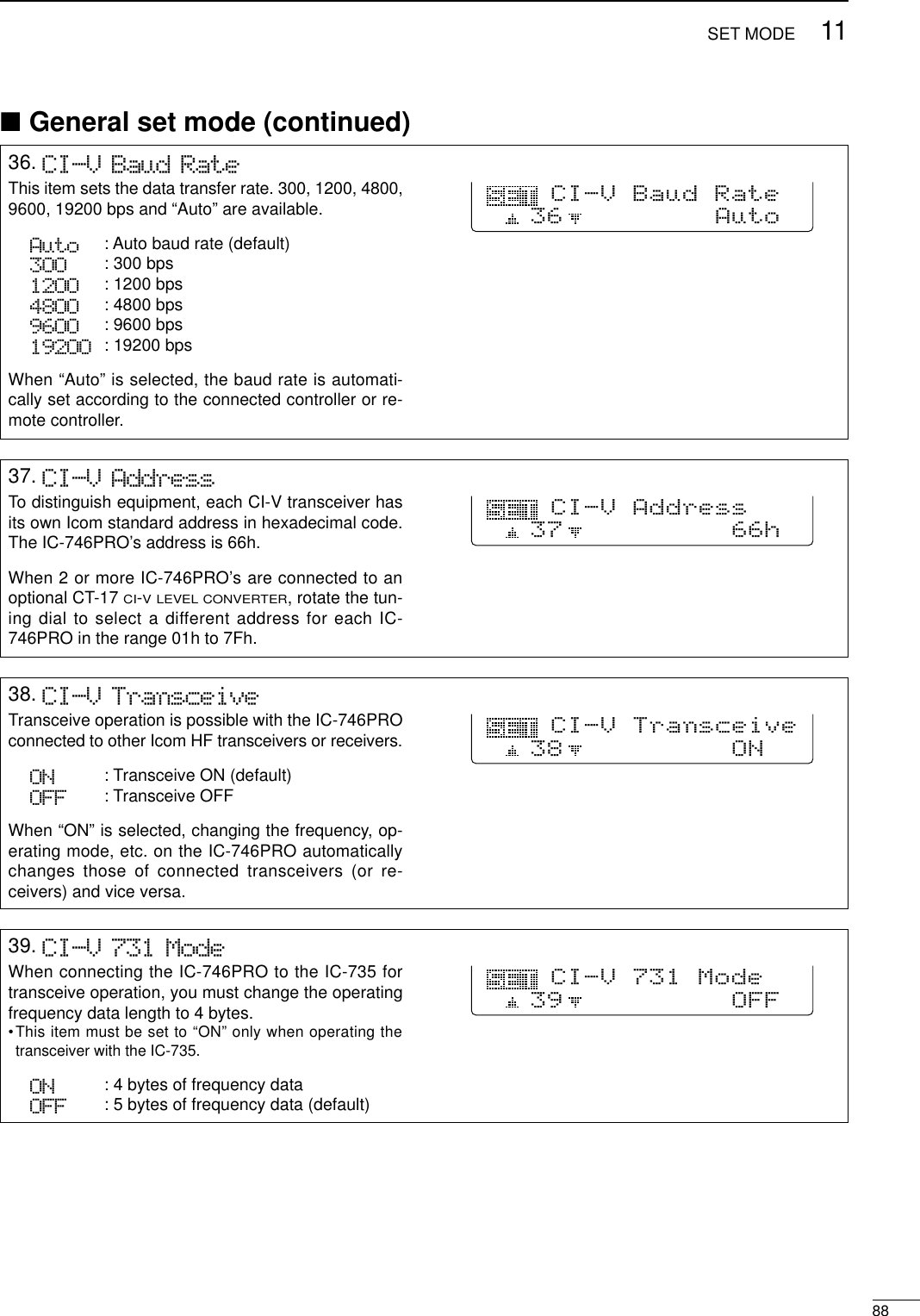
![1181SET MODE2. LCD BacklightThis item adjusts the brightness of the LCD from 0%to 100% in 1% steps.(default: 50%)LCD Backlight5O%2■General set mode DEntering set modeSet mode is used for programming infrequentlychanged values or conditions of functions. •Set mode operationqPush [MENU] several times to function menu indi-cation, if necessary.wPush [MENU] for 1 sec. to enter the set mode.ePush [F1 ≤] or [F2 ≥] to select the desired item.rSet the desired condition using the tuning dial.•Push [F3] for 1 sec. to select a default condition or value.uPush [MENU] to exit the set mode.DSet mode items1. LCD ContrastThis item adjusts the contrast of the LCD from 0% to100% in 1% steps.(default: 50%)LCD Contrast5O%13. Beep LevelThis item adjusts the volume level for confirmationbeep tones from 0% to 100% in 1% steps. Whenbeep tones, the item 6. Beep (p. 81), are turnedOFF, this setting has no effect.(default: 50%)Beep Level35O%4. Beep Level-lmtThis item allows you to set a maximum volume levelfor confirmation beep tones. Confirmation beep tonesare linked to the [AF] control until a specified volumelevel is reached—further rotation of the [AF] controlwill not increase the volume of the beep tones.ON Confirmation beep ON (default)OFF Confirmation beep OFFBeep Level-lmt4ON[F1 ≤]Tuning dial[MENU][F2 ≥]5. CAL. MarkerThis item is used for a simple frequency check of thetransceiver.ON Calibration marker ONOFF Calibration marker OFF (default)See p. 93 for calibration procedure.Turn the calibration marker OFF after checking thefrequency of the transceiver.Cal. Marker5OFF](https://usermanual.wiki/ICOM-orporated/IC-746PRO.Manual-Part-2/User-Guide-183823-Page-35.png)
![8211SET MODE6. BeepA beep sounds each time a switch is pushed to con-firm it. This function can be turned OFF for silent op-eration.ON Confirmation beep ON (default)OFF Confirmation beep OFFThe volume level can be set in 3. Beep Level.(p. 80)Beep6ON7. Band Edge BeepA beep sounds when an operating frequency entersor exits an amateur band. This functions independentof the confirmation beep setting (above).ON Band edge beep ON (default)OFF Band edge beep OFFThe volume level can be set in 3. Beep Level.(p. 80)Band Edge Beep7ON8. RF/SQL ControlThe [RF/SQL] control can be set as the RF/squelchcontrol (default), the squelch control only (RF gain isfixed at maximum) or ‘Auto’(RF gain control in SSB,CW and RTTY; squelch control in AM and FM).RF+SQL [RF/SQL] control as RF/squelch con-trol (default)SQL [RF/SQL] control as squelch controlAUTO [RF/SQL] control as RF gain controlin SSB, CW and RTTY; squelch con-trol in AM and FMRF/SQL Control8RF+SQL9. Meter Peak HoldThis item turns the meter peak hold function ON andOFF. When set to ON (default), peak meter readingare displayed for about 0.5 sec.Meter Peak Hold9ON10. COMP MeterThis item turns the COMP meter indication ON andOFF during transmit. When set to ON, the COMPmeter is displayed instead of the SWR meter.(default: OFF)1O OFFCOMP Meter ■General set mode (continued)](https://usermanual.wiki/ICOM-orporated/IC-746PRO.Manual-Part-2/User-Guide-183823-Page-36.png)
![8311 SET MODE11. Quick SPLITWhen this item is set to ON, pushing [SPLIT] for 1sec. sets transmit frequency using the displayed fre-quency and the split offset, set in SPLIT Offsetitem below, and activate split function automatically.ON Quick split ON (default)OFF Quick split OFF11ONQuick SPLIT 12. SPLIT OffsetThis item sets the offset (difference between transmitand receive frequencies) for the quick split function.The offset frequency can be set from –9.999 MHz to+9.999 MHz in 1 kHz steps.12O.OOOMHzSPLIT Offset13. SPLIT LOCKWhen this item is ON, the tuning dial can be used toadjust the transmit frequency while pushing [XFC]even while the dial lock function is activated.ON Split lock function ONOFF Split lock function OFF (default) 13OFFSPLIT LOCK14. DUP Offset HFThis item sets the offset (difference between transmitand receive frequencies) for the duplex operation.However, this setting is used to input the repeater off-set for an HF band only.The offset frequency can be set from 0.000 MHz to9.999 MHz in 1 kHz steps.14O.1OOMHzDUP Offset HF15. DUP Offset 50MThis item sets the offset (difference between transmitand receive frequencies) for the duplex operation.However, this setting is used to input the repeater off-set for a 50 MHz band only.The offset frequency can be set from 0.000 MHz to9.999 MHz in 1 kHz steps.15O.5OOMHzDUP Offset 5OM■General set mode (continued)16. DUP Offset 144MThis item sets the offset (difference between transmitand receive frequencies) for the duplex operation.However, this setting is used to input the repeater off-set for a 144 MHz band only.The offset frequency can be set from 0.000 MHz to9.999 MHz in 1 kHz steps.16O.6OOMHzDUP Offset 144M](https://usermanual.wiki/ICOM-orporated/IC-746PRO.Manual-Part-2/User-Guide-183823-Page-37.png)
![8411SET MODE17. One Touch RptrThis item turns the one touch repeater function to ON(DUP- or DUP+) and OFF. When [F2 DUP] is pushed for 1 sec. during M1, theselected offset direction and the programmed duplexoffset frequency (depending on the operating fre-quency band) is set with the displayed frequency.17DUP-One Touch Rptr](https://usermanual.wiki/ICOM-orporated/IC-746PRO.Manual-Part-2/User-Guide-183823-Page-38.png)
![8511 SET MODE22. [ANT] SwitchYou can set the antenna connector selection to auto-matic, manual or non-selection (when using 1 an-tenna only for the HF/50 MHz bands).Auto : The antenna switch is activated andthe band memory memorizes the se-lected antenna. (default)Manual: The antenna switch is activated andselects an antenna manually.OFF : The antenna switch is not activatedand does not function. The [ANT1] con-nector is always selected in this case.22Auto[ANT] Switch23. SPEECH LanguageWhen the optional UT-102 VOICE SYNTHESIZER UNITisinstalled, you can select between English and Japan-ese as the language.English : Announces in English (default)Japanese : Announces in Japanese See p. 89 for unit installation.23EnglishSPEECH Language24. SPEECH SpeedWhen the optional UT-102 VOICE SYNTHESIZER UNITisinstalled, you can select between faster or slowersynthesizer output.HIGH : Announces faster (default)LOW : Announces slower See p. 89 for unit installation.24HIGHSPEECH Speed25. SPEECH S-LevelWhen the optional UT-102 VOICE SYNTHESIZER UNITisinstalled, you can have frequency, mode and signallevel announcement. Signal level announcement canbe deactivated if desired.ON : Announces operating frequency, modeand receiving signal level. (default)OFF : Announces operating frequency andmode only.See p. 89 for unit installation.25ONSPEECH S-Level26. Memory Pad ChThis item sets the number of memo pad channelsavailable. 5 or 10 memo pads can be set.5: 5 memo pads (default)10: 10 memo pads265Memory Pad Ch■General set mode (continued)](https://usermanual.wiki/ICOM-orporated/IC-746PRO.Manual-Part-2/User-Guide-183823-Page-39.png)
![8611SET MODE27. DIAL Auto TSThis item sets the auto tuning step function. When ro-tating the tuning dial rapidly, the tuning step automat-ically changes several times as selected. There are 2 type of auto tuning steps: HIGH (Fastest)and LOW (Faster).HIGH : Auto tuning step is turned ON. Approx. 5 times fastest tuning stepduring rapid rotation (default)LOW : Auto tuning step is turned ON. Approx. 2 times faster tuning step dur-ing rapid rotationOFF : Auto tuning step is turned OFF.27HIGHDIAL Auto TS28. MIC U/D SpeedThis item sets the rate at which frequencies arescanned when the microphone [UP]/[DN] switchesare pushed and held. High or low can be selected.HIGH : High speed (default, 50 tuningsteps/sec.)LOW : Low speed (25 tuning steps/sec.)28HIGHMIC U/D Speed29. Quick RIT ClearThis item selects the RIT/∂TX frequency clearing in-struction with [PBTC].ON : Clears the RIT/∂TX frequency when[PBTC] is pushed momentarily. OFF : Clears the RIT/∂TX frequency when[PBTC] is pushed for 1 sec. (default)29OFFQuick RIT Clear30. BW Popup (PBT)This item turns the PBT shifting value indication ONand OFF during [TWIN PBT] control operation. Whenset to ON, the shifting value is displayed above themulti-function switches.(default: ON)3OONBW Popup (PBT)31. BW Popup (FIL)This item turns the IF filter width indication ON andOFF when selecting with [FILTER]. When set to ON,the filter width is displayed above the multi functionswitches.(default: ON)31ONBW Popup (FIL)■General set mode (continued)](https://usermanual.wiki/ICOM-orporated/IC-746PRO.Manual-Part-2/User-Guide-183823-Page-40.png)
![8711 SET MODE32. SSB/CW Synchronous TuningThis item selects the displayed frequency shift func-tion from ON and OFF.When this function is activated, the receiving signalcan be kept to receive even when the operating modeis changed between SSB and CW. ON : The displayed frequency shifts whenthe operating mode is changed be-tween SSB and CW.OFF : The displayed frequency does not shift.(default)The frequency shifting value may differ accordingto the CW pitch setting.32OFFSSB/CW Sync Tun33. CW Normal SideSelects the carrier point of CW mode from LSB andUSB.LSB : The carrier point is set to LSB side.(default)USB : The carrier point is set to USB side.33LSBCW Normal Side34. KEYER 1st MenuThis item selects the appearing menu when [F4 KEY]is pushed in M1 at first, from KEYER-Root andKEYER-SEND.KEYER-Root : Selects memory keyermenu at first (default)KEYER-SEND : Selects keyer SEND menuat first34 KEYER-RootKEYER 1st Menu■General set mode (continued)35. External KeypadThis item sets the external keypad capability.OFF : External keypad does not func-tion. (default)KEYER SEND : Pushing one of external keypadswitches, transmits the desiredkeyer memory contents duringCW mode operation.For your informationThe diagram as at right shows the equivalent circuit ofan external keypad and connects to the pin 3 andpin 7 of the [MIC] connector (p. 12)To [MIC] connector pin e To [MIC] connector pin u 1.5kΩ±5%1.5kΩ±5%2.2kΩ±5%4.7kΩ±5%S1(T1/M1)S2(T2/M2)S3(T3/M3)S4(T4/M4)USER EXTERNAL KEYPAD35OFFExternal Keypad](https://usermanual.wiki/ICOM-orporated/IC-746PRO.Manual-Part-2/User-Guide-183823-Page-41.png)
![8911 SET MODE■Tone control set modeDEntering tone control set modeTone levels (bass and treble) for each transmit and re-ceive audio can be set for each phone mode indepen-dently. •Set mode operationqPush [MENU] several times to select M2.wPush [F4 TCN] to select the tone control set mode.ePush [F1 ≤] or [F2 ≥] to select the desired item.rPush [SSB] or [AM/FM] to select the desired oper-ating mode.tSet the desired condition using the tuning dial.•Push [F3] for 1 sec. to select a default value.yPush [MENU] to exit the set mode.DTone control set mode items[F1 ≤]Tuning dial[MENU][F2 ≥] [F4 TCN]1. TX BassThis item adjusts the bass level of the transmit audiotone from –5 dB to +5 dB in 1 dB steps.TX Bass SSBO12. TX TrebleThis item adjusts the treble level of the transmit audiotone from –5 dB to +5 dB in 1 dB steps.TX Treble SSBO23. RX BassThis item adjusts the bass level of the receive audiotone from –5 dB to +5 dB in 1 dB steps.RX Bass SSBO34. RX TrebleThis item adjusts the treble level of the receive audiotone from –5 dB to +5 dB in 1 dB steps.RX Treble SSBO4](https://usermanual.wiki/ICOM-orporated/IC-746PRO.Manual-Part-2/User-Guide-183823-Page-43.png)
![1290OPTION INSTALLATION■Opening the transceiver’s caseFollow the case and cover opening procedures shownhere when you want to install an optional unit or adjustthe internal units, etc.CAUTION: DISCONNECT the DC power cablefrom the transceiver before performing any work onthe transceiver. Otherwise, there is danger of elec-tric shock and/or equipment damage.qRemove 2 screws from the left side of the trans-ceiver to remove the carrying handle as shown atright.wRemove 6 screws from the top of the transceiverand 6 screws from the sides, then lift up the topcover.eTurn the transceiver upside down.rRemove 6 screws from the bottom of the trans-ceiver, then lift up the bottom cover.■UT-102 VOICE SYNTHESIZER UNITThe UT-102 announces the accessed readout’s fre-quency, mode, etc. (S-meter level can also be an-nounced— p. 84) in a clear, electronically-generatedvoice, in English (or Japanese).➥Push [LOCK/SPCH] for 1 sec. to announce the fre-quency, etc.qRemove the top and bottom covers as shownabove.wRemove the protective paper attached to the bot-tom of the UT-102 to expose the adhesive strip.ePlug UT-102 into J1920 on the MAIN unit as shownin the diagram at right.rAdjust the trimmer, SPCH LVL: R1925 on the MAINunit, to set the speech level if desired. Refer the il-lustration at right.tReturn the top and bottom covers to their originalpositions.MAIN unitUT-102J1920R1925](https://usermanual.wiki/ICOM-orporated/IC-746PRO.Manual-Part-2/User-Guide-183823-Page-44.png)
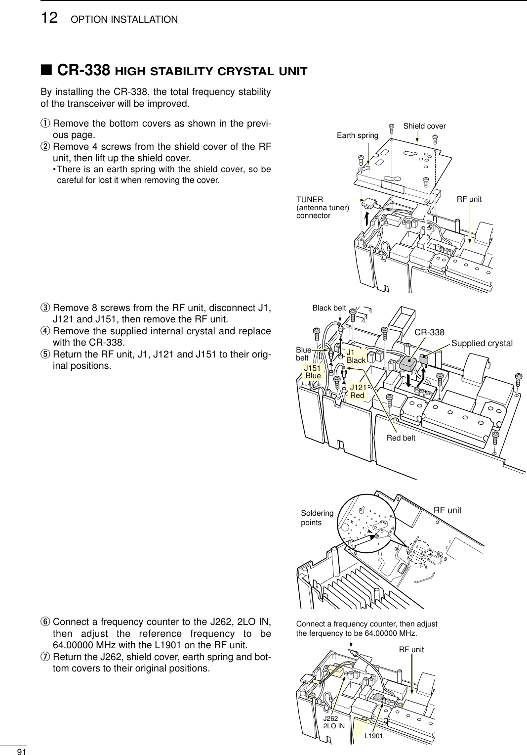
![1392MAINTENANCESCAN■TroubleshootingThe following chart is designed to help you correctproblems which are not equipment malfunctions. If you are unable to locate the cause of a problem orsolve it through the use of this chart, contact your near-est Icom Dealer or Service Center.PROBLEM POSSIBLE CAUSE SOLUTION REF.RECEIVE POWERTRANSMITPower does not come onwhen the [POWER] switchis pushed.No sounds come out fromthe speaker.Sensitivity is too low, andonly strong signals are au-dible.Received audio is unclearor distorted.The [ANT] switch does notfunctionTransmitting is impossible.Output power is too low.No contact possible withanother station.Transmit signal is unclearor distorted.Repeater cannot be ac-cessed.Programmed scan doesnot stop.Programmed scan doesnot start.Memory scan does notstartSelect memory scan doesnot start•Power cable is improperly connected.•Fuse is blown.•Volume level is too low.•The squelch is closed.•The transceiver is in transmitting condition.•The antenna is not connected properly.•The antenna for another band is selected.•The antenna is not properly tuned.•The attenuator is activated.•Wrong operating mode is selected.•PBT function is activated.•Noise blanker is turned ON when receiving astrong signal.•Preamp is activated.•The noise reduction is activated and the [NR]control is too far clockwise.•The antenna switch has not been activated.•The operating frequency is not set to a hamband.•[RF PWR] is set too far counterclockwise•[MIC GAIN] is set too far counterclockwise•The antenna for another band is selected.•The antenna is not properly tuned.•RIT or ∂TX function is activated.•Split frequency and/or duplex function are acti-vated.•[MIC GAIN] is set too far clockwise•Split frequency or duplex function is not acti-vated.•Programmed subaudible tone frequency iswrong.•Squelch is open.•[RF/SQL] is assigned to RF gain control andsquelch is open.•The same frequencies have been programmedin scan edge memory channels P1 and P2.•2 or more memory channels have not beenprogrammed.•2 or more memory channels have not beendesignated as select channels.•Re-connect the DC power cable correctly.•Check for the cause, then replace the fuse withthe spare one.(Fuses are installed in the DC power cable andthe internal PA unit.)•Rotate [AF] clockwise to obtain a suitable lis-tening level.•Turn [RF/SQL] to 10 o’clock position to open thesquelch.•Push [TRANSMIT] to receive or check theSEND line of an external unit, if desired.•Re-connect to the antenna connector.•Select an antenna suitable for the operating fre-quency.•Push [TUNER] for 1 sec. to manually tune theantenna.•Push [P.AMP/ATT] for 1 sec. to select “ATT OFF.”•Select a suitable operating mode.•Push [PBTC] for 1 sec. to reset the function•Push [NB] to turn the noise blanker OFF.•Push [P.AMP/ATT] once or twice to turn thefunction OFF.•Set the [NR] control for maximum readability.•Set the antenna switch in set mode to “Auto” or“Manual.”•Set the frequency to a ham band.•Rotate [RF PWR] clockwise.•Set [MIC GAIN] to a suitable position.•Select an antenna suitable for the operating fre-quency.•Push [TUNER] for 1 sec. to manually tune theantenna.•Push [RIT] or [∂TX] to turn the function OFF.•Push [SPLIT] and/or [F2 DUP] (in M1) to turnthe function OFF.•Set [MIC GAIN] to a suitable position.•Push [SPLIT] and/or [F2 DUP] (in M1) to turnthe function ON•Reset the frequency using set mode.•Set [RF/SQL] to the threshold point.•Reset [RF/SQL] control assignment and set it tothe threshold point.•Program different frequencies in scan edgememory channel P1 and P2.•Program more than 2 memory channels.•Designate more than 2 memory channels as se-lect channels for the scan.p. 16p. 92p. 23p. 24p. 25—p. 75pgs. 76,77p. 48p. 23p. 52p. 51p. 48p. 53p. 84p. 19p. 25p. 25p. 75pgs. 76,77pgs. 48,56pgs. 58,44p. 25pgs. 44,58p. 45p. 24pgs. 24,81p. 66p. 63p. 72](https://usermanual.wiki/ICOM-orporated/IC-746PRO.Manual-Part-2/User-Guide-183823-Page-46.png)
![9313 MAINTENANCE■Fuse replacementIf a fuse blows or the transceiver stops functioning, tryto find the source of the problem, and replace the dam-aged fuse with a new, rated fuse.The IC-746PRO has 2 types of fuses installed fortransceiver protection.•DC power cable fuses ................................FGB 30 A•Circuitry fuse ................................................FGB 5 ADDC power cable fuse replacementRefer the figure illustrated at right for the DC powercable fuse replacement.DCircuitry fuse replacementThe 13.8 V DC from the DC power cable is applied toall units in the IC-746PRO, except for the power am-plifier, through the circuitry fuse. This fuse is installed inthe PA unit.qRemove the top cover as shown on p. 89.wRemove 11 screws from the PA shielding plate, thenremove the plate.eReplace the circuitry fuse as shown in the diagramat right.rReplace the PA shielding plate and top cover.■Tuning dial brake adjustmentThe tension of the tuning dial may be adjusted to suityour preference.The brake adjustment screw is located on the rightside of the tuning dial. See the figure at right.Turn the brake adjustment screw clockwise or counter-clockwise to obtain a comfortable tension level whileturning the dial continuously and evenly in one direction.PROBLEM POSSIBLE CAUSE SOLUTION REF.DISPLAYThe displayed frequencydoes not change properly.•The dial lock function is activated.•A set mode screen is selected.•The internal CPU has malfunctioned.•Push [LOCK/SPCH] to turn the function OFF.•Push [MENU] several times to exit the setmode.•Reset the CPU.p. 53—p. 9330 A fuseFuseCAUTION:DISCONNECT the DC power cablefrom the transceiver when changing a fuse.LightHeavy](https://usermanual.wiki/ICOM-orporated/IC-746PRO.Manual-Part-2/User-Guide-183823-Page-47.png)
![■Resetting the CPUWhen first applying power or when the function seemsto be displaying erroneous information, reset the CPUas follow:qMake sure the transceiver power is OFF.wWhile pushing [M-CL] and [F-INP], push [POWER]for 1 sec. to turn power ON.•The internal CPU is reset.•The transceiver displays its initial VFO frequency whenresetting is complete.eCorrect the set mode settings after resetting, if de-sired.NOTE: Resetting CLEARS all programmed con-tents in memory channels and returns programmedvalues in set mode to default values.■Frequency calibration (approximate)A very accurate frequency counter is required to cali-brate the frequency of the transceiver. However, arough check may be performed by receiving radio sta-tion WWV, or other standard frequency signals.CAUTION: Your transceiver has been thoroughlyadjusted and checked at the factory before beingshipped. You should not calibrate frequencies, ex-cept for special reasons.qPush [SSB] to select USB mode.wPush [PBTC] for 1 sec. to clear the PBT settingsand make sure that the RIT/∂TX function is not ac-tivated.eSet the frequency to the standard frequency stationminus 1 kHz.•When receiving WWV (10.000.00 MHz) as a standardfrequency, set the operating frequency for 9.999.00 MHz.•Other standard frequencies can also be used.rPush [MENU] several times to select M1 or M2, ifnecessary.tPush [MENU] for 1 sec. to select the set modescreen.yPush [F1 ≤] or [F2 ≥] several times to select theCAL. Marker item.uRotate the tuning dial clockwise to turn the calibra-tion marker ON.•Side tone may be heard.iAdjust [CAL] pot on the rear side of the transceiverfor a zero beat with the received standard signal.•Zero beat means that two signals are exactly the samefrequency, resulting in a single tone being emitted.oRotate the tuning dial counterclockwise to turn thecalibration marker OFF.!0 Push [MENU] to exit set mode.CAL. Marker5ON[SSB][MENU] [PBTC][RF/SQL] [AF] [P.AMP/ATT] [CLEAR][RIT][CAL]• Calibration marker item[POWER] [F-INP] [M-CL]9413MAINTENANCE](https://usermanual.wiki/ICOM-orporated/IC-746PRO.Manual-Part-2/User-Guide-183823-Page-48.png)
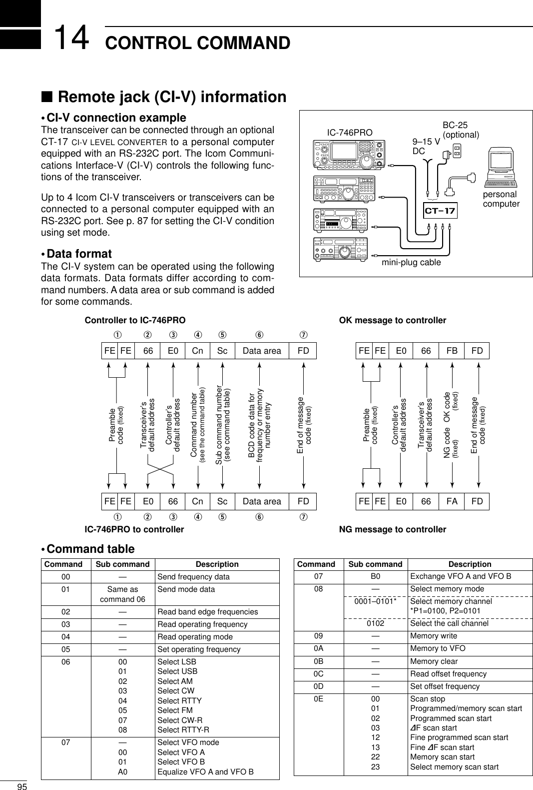
![9614CONTROL COMMAND•Command table (continued)Command Sub command Description0E A1–A7 Set ∂F scan span (A1=±5 kHz,A2=±10 kHz, A3=±20 kHz,A4=±50 kHz, A5=±100 kHz, A6=±500 kHz, A7=±1 MHz)B0 Set as non-select channelB1 Set as select channelD0 Set scan resume OFFD3 Set scan resume ON0F 00 Turn the split function OFF01 Turn the split function ON10 Select simplex operation11 Select –DUP operation12 Select +DUP operation10 00 Select 10 Hz (1 Hz) tuning step01 Select 100 Hz tuning step02 Select 1 kHz tuning step03 Select 5 kHz tuning step04 Select 9 kHz tuning step05 Select 10 kHz tuning step06 Select 12.5 kHz tuning step07 Select 20 kHz tuning step08 Select 25 kHz tuning step11 —Select/read attenuator (0=OFF,1=ON)12 —Select/read antenna selection(0=ANT1, 1=ANT2)13 00 Announce with voice synthesizer01 (00=all data; 01=frequency and 02 S-meter level; 02=receive mode)14 01 + Level data [AF] level setting (0=max. CCW to255=max. CW)02 + Level data [RF] level setting (0=max. CCW to255=11 o’clock)03 + Level data [SQL] level setting (0=11 o’clock to255=max. CW)06 + Level data [NR] level setting (0=min. to255=max.)07 + Level data Inside [TWIN PBT] setting or IFshift setting (0=max. CCW,128=center, 255=max. CW)08 + Level data Outside [TWIN PBT] setting (0=max. CCW, 128=center,255=max. CW)09 + Level data [CW PITCH] setting (0=300 Hz,128=600 Hz, 255=900 Hz)0A + Level data [RF PWR] setting (0=mini. to255=max.)0B + Level data [MIC GAIN] setting (0=mini. to255=max.)0C + Level data [KEY SPEED] setting (0=slow to255=fast)0D + Level data [NOTCH] setting (0=low freq. to255=high freq.)0E + Level data COMP Level Delay setting (0=0 to10=10)0F + Level data Break-IN DELAY setting (20=2.0dto 130=13.0d)15 01 Read squelch condition02 Read S-meter level11 Read RF power meter 12 Read SWR meter 13 Read ALC meter 16 02 Preamp (0=OFF; 1=preamp 1;2=preamp 2)Command Sub command Description16 12 AGC selection (0=OFF; 1=Slow;2=Mid; 3=Fast)22 Noise blanker (0=OFF; 1=ON)40 Noise reduction (0=OFF; 1=ON)41 Auto notch (0=OFF; 1=ON)42 Repeater tone (0=OFF; 1=ON)43 Tone squelch (0=OFF; 1=ON)44Speech compressor (0=OFF; 1=ON)45 Monitor (0=OFF; 1=ON)46 VOX function (0=OFF; 1=ON)47 Break-in (0=OFF; 1=semi break-in; 2=full break-in)48 Manual notch (0=OFF; 1=ON)49 RTTY filter (0=OFF; 1=ON)4B DTCS (0=OFF; 1=ON)4C VSC (0=OFF; 1=ON)19 00 Read the transceiver ID1A 00 Send/read memory contents (seep. 97 for details)01 Send/read band stacking registercontents (see p. 97 for details)02 Send/read memory keyer con-tents (see p. 97 for details)03 Send/read the selected filter width(0=50 Hz to 40/31=3600/2700 Hz)04 Send/read the selected AGC timeconstant (0=OFF, 1=0.1/0.3 sec. to13=6.0/8.0 sec.)0501 Send/read LCD contrast (0=0% to255=100%)0502 Send/read LCD backlight (0=0% to255=100%)0503 Send/read beep gain (0=min. to255=max.)0504 Send/read beep gain limit (0=OFF,1=ON)0505 Send/read calibration marker(0=OFF, 1=ON)0506 Send/read confirmation beep(0=OFF, 1=ON)0507 Send/read band edge beep(0=OFF, 1=ON)0508 Send/read RF/SQL control set(0=Auto, 1=SQL, 2=RF+SQL)0509 Send/read meter peak hold set(0=OFF, 1=ON)0510 Send/read COMP meter set(0=OFF, 1=ON)0511 Send/read quick split set (0=OFF,1=ON)0512 Send/read split offset –9.999 to+9.999 MHz (see p. 98 for details)0513 Send/read split lock set (0=OFF,1=ON)0514 Send/read duplex offset 0.000 to9.999 MHz for HF (see p. 98 fordetails)0515 Send/read duplex offset 0.000 to9.999 MHz for 50 MHz band (seep. 98 for details)0516 Send/read duplex offset 0.000 to9.999 MHz for 144 MHz band(see p. 98 for details)](https://usermanual.wiki/ICOM-orporated/IC-746PRO.Manual-Part-2/User-Guide-183823-Page-50.png)
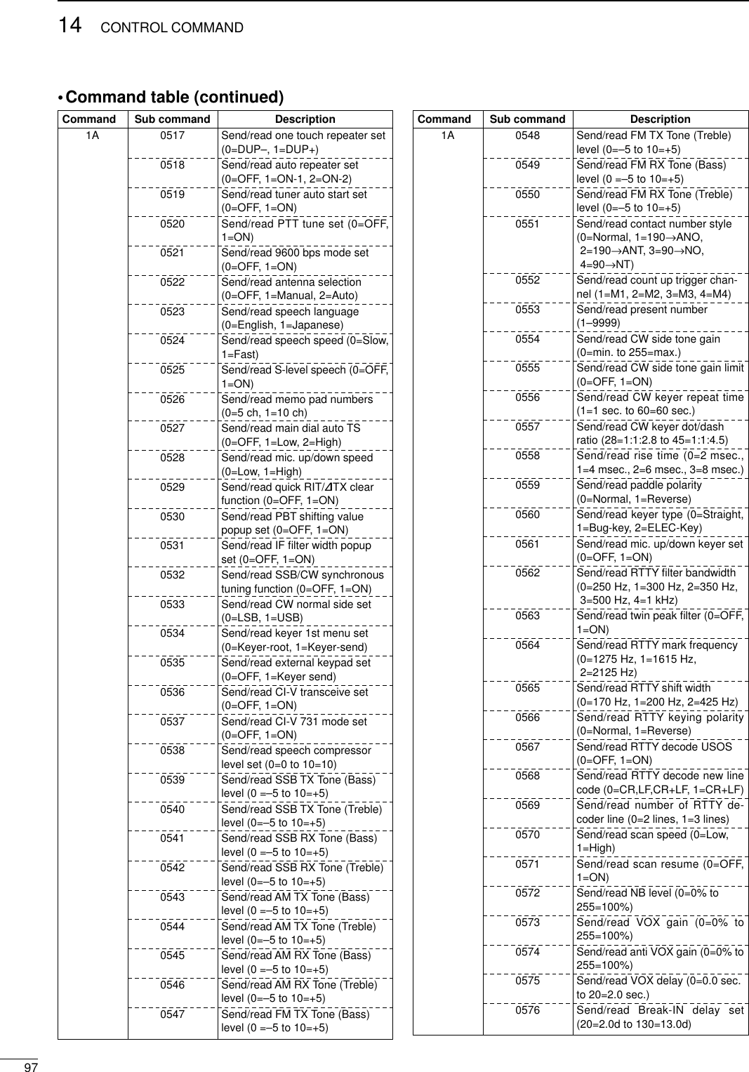
![9814CONTROL COMMAND•Command table (continued)DTo send/read memory contentsWhen sending or reading memory contents, additional codeas follows must be added to appoint the memory channel.➥Additional code: 0000–0102 (0100=P1, 0101=P2, 0102=Call)DBand stacking registerTo send or read the desired band stacking register’s con-tents, combined code of the frequency band and registercodes as follows are used. For example, when sending/reading the oldest contents inthe 21 MHz band, the code “0703” is used.•Frequency band code •Register code DCodes for memory keyer contentsTo send or read the desired memory keyer contents, thechannel and character codes as follows are used. •Channel code •Character’s code DCodes for memory name contentsTo send or read the desired memory name settings, the char-acter codes, instructed codes for memory keyer contents asabove, and follows are additionally used. •Character’s code— Alphabetical characters•Character’s code— Symbols Character ASCII code Character ASCII codea–z61–7A ——Code Frequency band Frequency range (unit: MHz)01 1.8 1.800000–1.99999902 3.5 3.400000–4.09999903 7 6.900000–7.49999904 10 9.900000–10.49999905 14 13.900000–14.49999906 18 17.900000–18.49999907 21 20.900000–21.49999908 24 24.400000–25.09999909 28 28.000000–29.99999910 50 50.000000–54.00000011 144 144.000000–148.00000012 GENE Other than aboveCode Registered number01 1 (latest)02 203 3 (oldest)Character ASCII code Description0–930–39 NumeralsA–Z41–5A Alphabetical charactersspace 20 Word space / 2F Symbol? 3F Symbol, 2C Symbol. 2E Symbol^ 5E e.g., to send BT, enter ^4254✱2A Inserts contact number (can beused for 1 channel only)Code Channel number01 M102 M203 M304 M4Command Sub command Description1A 0577 Send/read MONITOR level (0=0%to 255=100%)06 Send/read DATA mode (0=OFF,1=ON)07 Send/read SSB transmit band-width (0=WIDE, 1=MID, 2=NAR)08 Send/read DSP filter shape(0= sharp, 1= soft)1B 00 Set/read repeater tone frequency(see p. 98 for details)01 Set/read TSQL tone frequency(see p. 98 for details)02 Set/read DTCS code and polarity(see p. 98 for details)1C 00 Set/read the transceiver’s condi-tion (0=Rx; 1=Tx)01 Set/read antenna tuner condition (0=OFF, 1=ON, 2=Start tuning orwhile tuning)Character ASCII code Character ASCII code!21#23$24%25&26¥5C?3F”22’27`60+2B–2D:3A;3B=3D<3C>3E( 28)29[5B]5D{7B}7D|7C_5F–7E](https://usermanual.wiki/ICOM-orporated/IC-746PRO.Manual-Part-2/User-Guide-183823-Page-52.png)
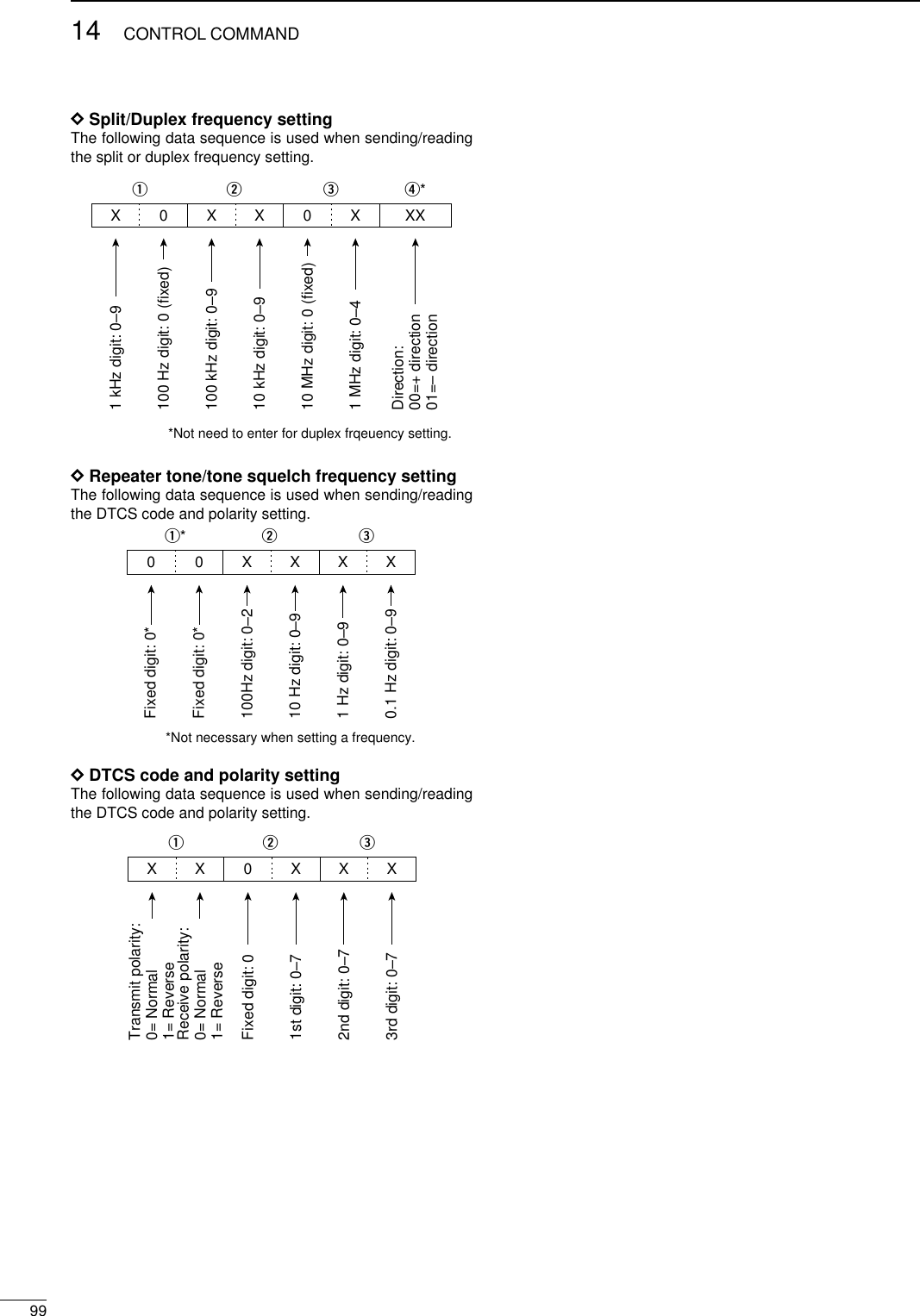
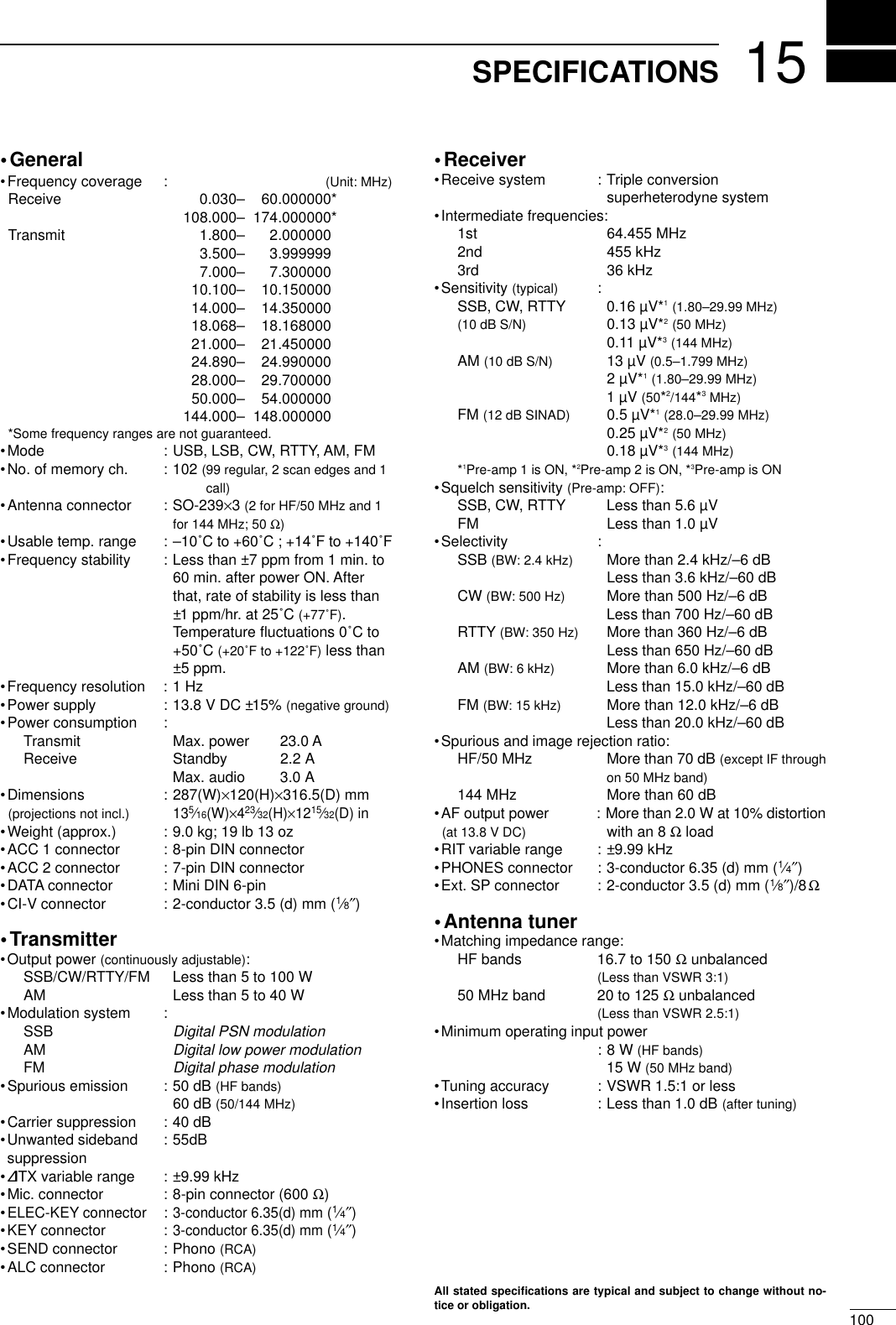
![16101OPTIONSIC-PW1 HF/50 MHz ALL BAND 1 kW LINEAR AMPLIFIERFull-duty 1 kW linear amplifier including an automatic antenna tuner. Hasautomatic tuning and band selection capability. Full break-in (QSK) oper-ation is possible. The amplifier/power supply unit and the remote controlunit are separated.AH-4 HF/50 MHz AUTOMATICANTENNA TUNERSpecially designed to tune a longwire antenna for portable or mobileHF operation. The PTT tuner startfunction provides simple operation.•Input power rating: 120 WAH-2b ANTENNA ELEMENTA 2.5 m long an-tenna element formobile operationwith the AH-4.•Frequency coverage:7–54 MHz bandswith the AH-4SM-20 DESKTOP MICROPHONEUnidirectional, electret microphonefor base station operation. Includes[UP]/[DOWN] switches and a lowcut function.SP-21 EXTERNAL SPEAKERDesigned for base station opera-tion.•Input impedance: 8 Ω•Max. input power: 5 WCT-17 CI-V LEVEL CONVERTERFor remote transceiver controlusing a personal computer. Youcan change frequencies, operatingmode, memory channels, etc.UT-102 VOICE SYNTHESIZER UNITAnnounces the receive frequency, modeand S-meter level in a clear, electroni-cally-generated voice, in English (orJapanese).SP-20 EXTERNAL SPEAKER4 audio filters; headphone jack; can con-nect to 2 transceivers.•Input impedance: 8 Ω•Max. input power: 5 WCR-338 HIGH STABILITY CRYSTALUNITContains a temperature-compensatingoven heater and crystal unit for improvedfrequency stability.•Frequency stability: ±0.5 ppmHM-36 HAND MICROPHONEHand microphone equipped with[UP]/[DOWN] switches.PS-125 DC POWER SUPPLYLight weight switching regulatorsystem power supply.•Output voltage: 13.8 V DC•Max. current drain: 25 A](https://usermanual.wiki/ICOM-orporated/IC-746PRO.Manual-Part-2/User-Guide-183823-Page-55.png)