ICOM orporated IC-746PRO Amateur HF \ VHF Scanning Transceiver User Manual 746PRO INSTRUCTION MANUAL EN pd
ICOM Incorporated Amateur HF \ VHF Scanning Transceiver 746PRO INSTRUCTION MANUAL EN pd
Contents
- 1. Manual Part 1
- 2. Manual Part 2
Manual Part 2
5
47
FUNCTIONS FOR RECEIVE
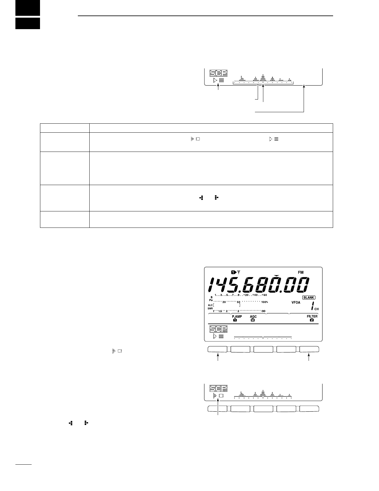
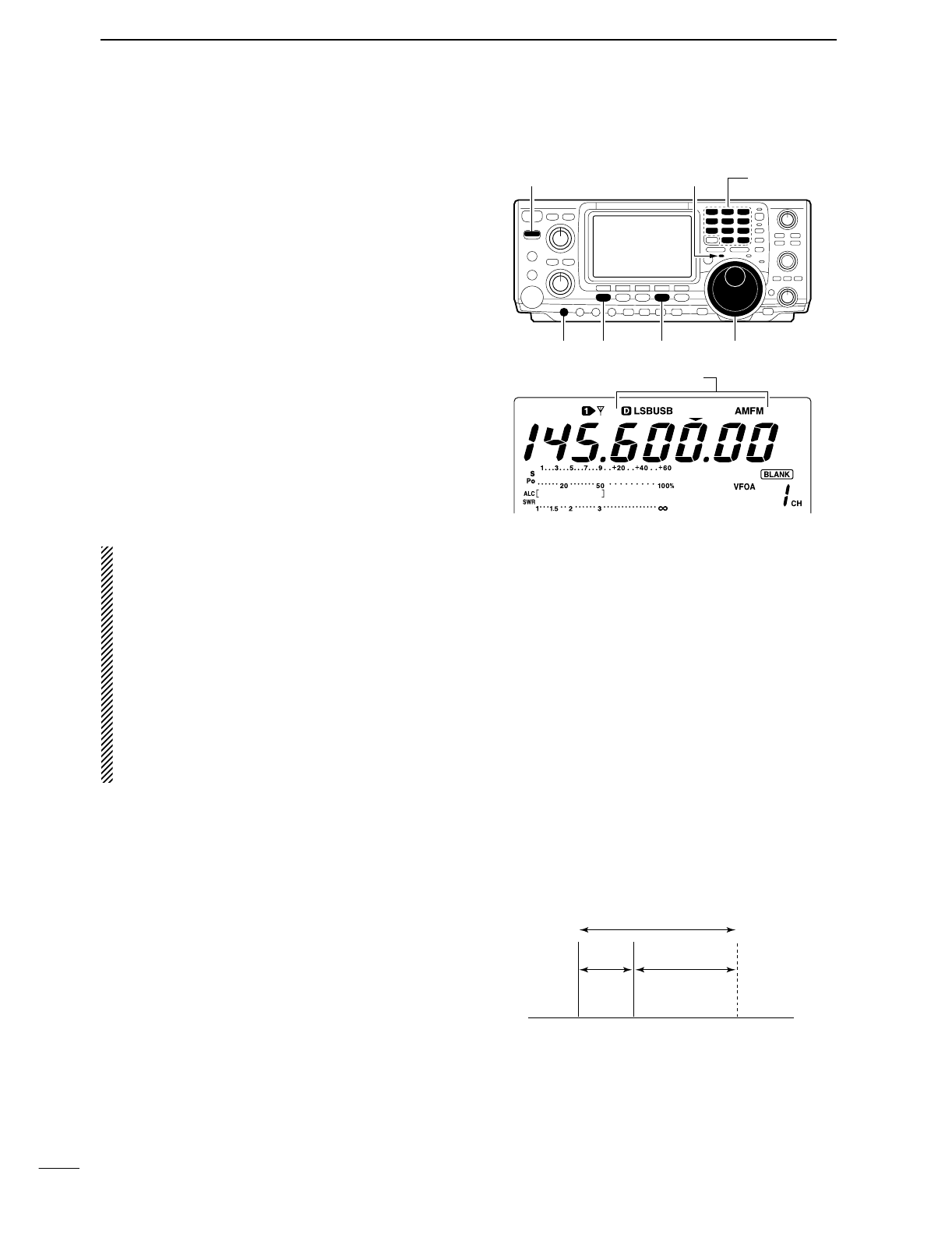
■Simple band scope
The band scope function allows you to visually check
signal condition around a specified frequency. The IC-
746PRO’s band scope function can be used in any op-
erating mode and frequency band.
The band scope measures receive signal conditions
over a specified range on either side of a selected fre-
quency in either VFO or memory modes.
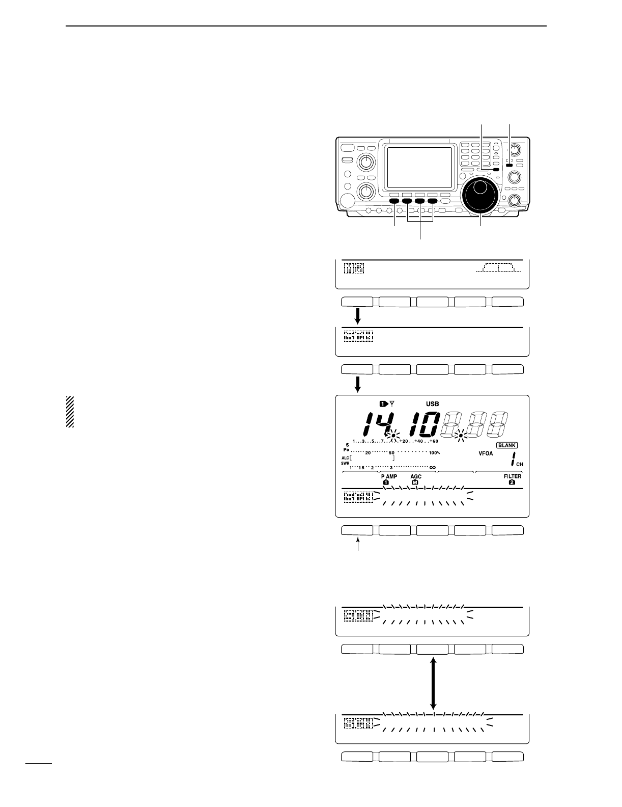
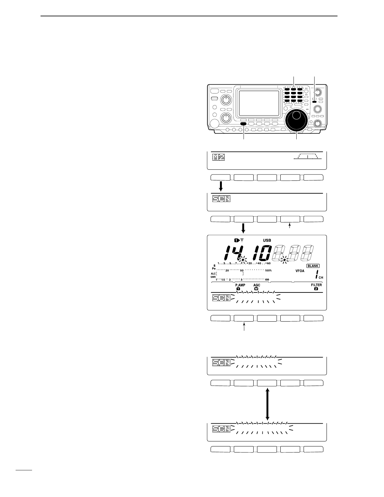
qRotate the tuning dial to tune a frequency.
wWhile M1 is selected, push [F5 SCP] to select the
band scope menu.
•Starts sweeping automatically with the previously se-
lected sweeping step.
•During sweep, received signals cannot be heard.
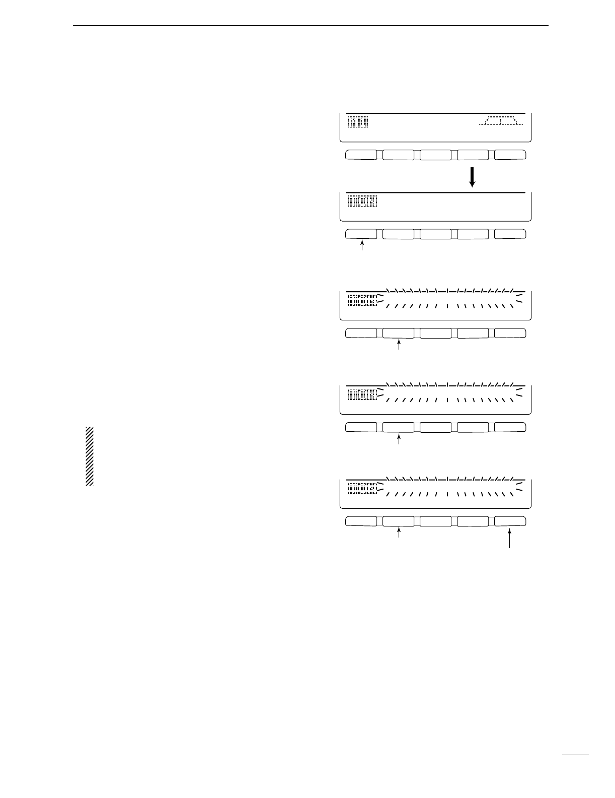
ePush [F5 STEP] several times to select the desired
sweep step.
rPush [F1] to start sweeping, then stop automatically
after sweeping.
•Push [F1] for 1 sec. to start continuous sweeping. In this
case, it is necessary to push [F1] to stop sweeping.
•During sweep operation “” appears and received
signals cannot be heard.
•If there is a lot of signal noise, turn the preamp OFF and
the attenuator ON to reduce the signal input level and
improve the readability of the band scope.
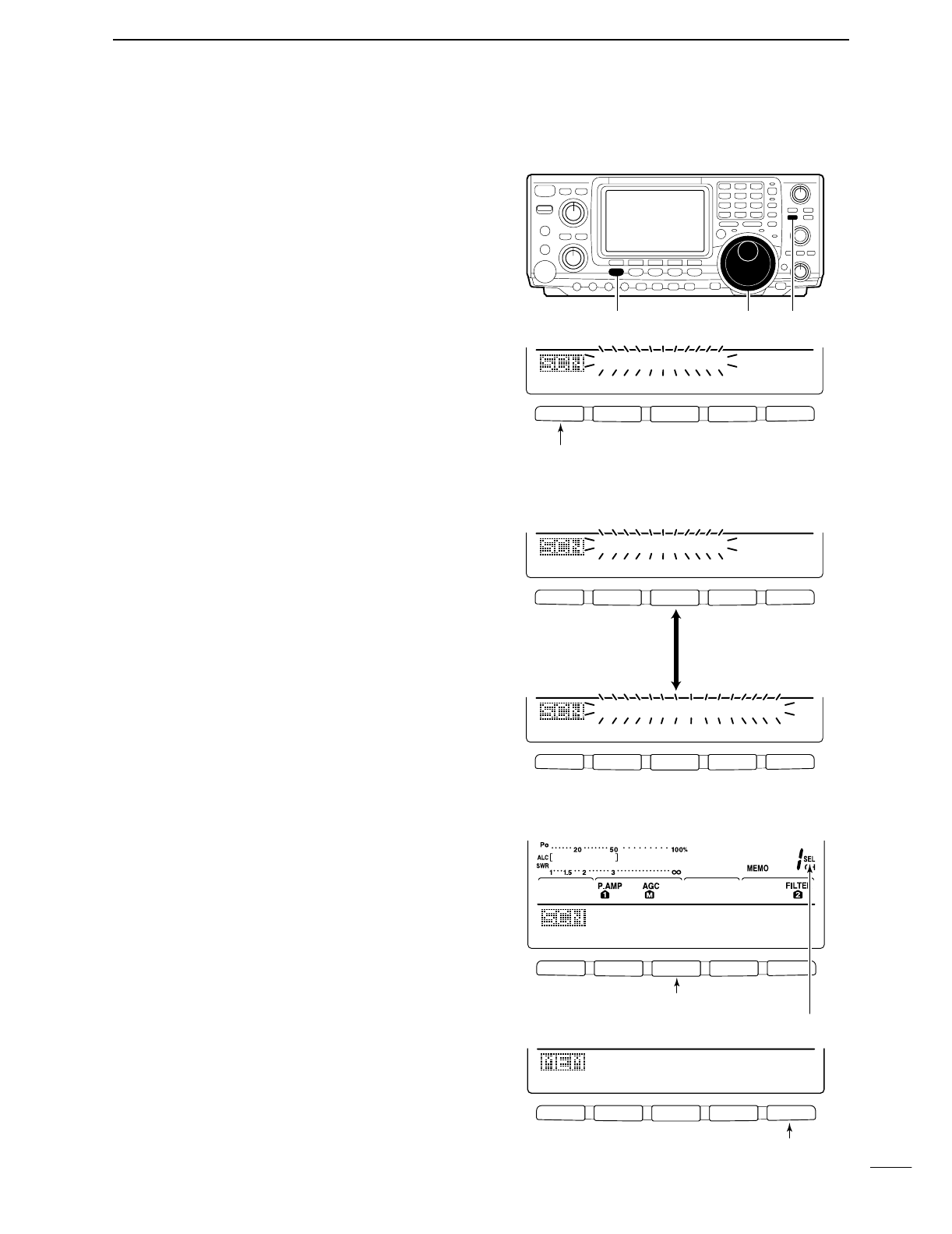
tWhen rotating the tuning dial and finding a signal
you wish to communicate on, simple communicate
normally.
•If you want to return to the previous frequency (before
rotating the tuning dial), push [F3] for 1 sec.
•If the selected frequency is set outside of the sweeped
range, flashes.
yWhile receiving, if you want to update the band con-
ditions, repeat steps eand ras above.
“ ” or “ ”
0.5k
STEP
Sweep indicator
Band scope indicator
Frequency indicator mark
Sweep step indicator
INDICATOR
Sweep
Band scope in-
dicator
Frequency
indicator mark
Sweep step
DESCRIPTION
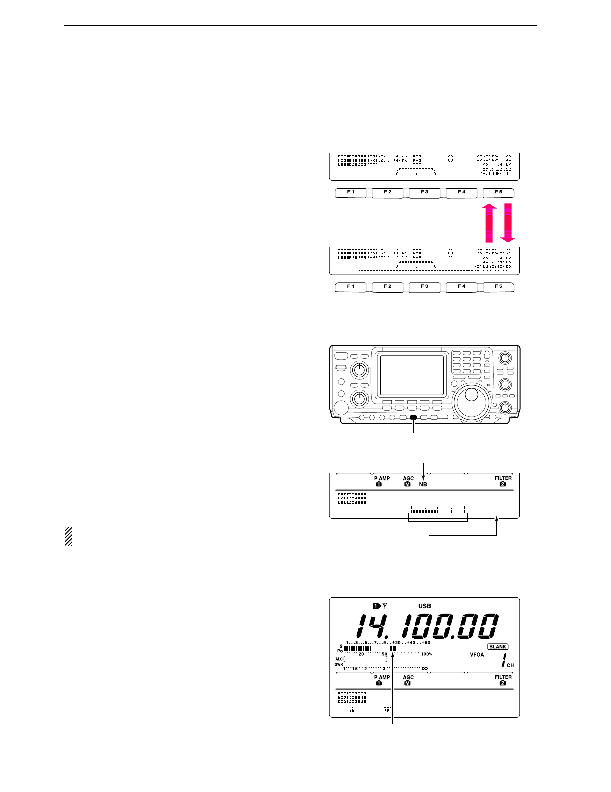
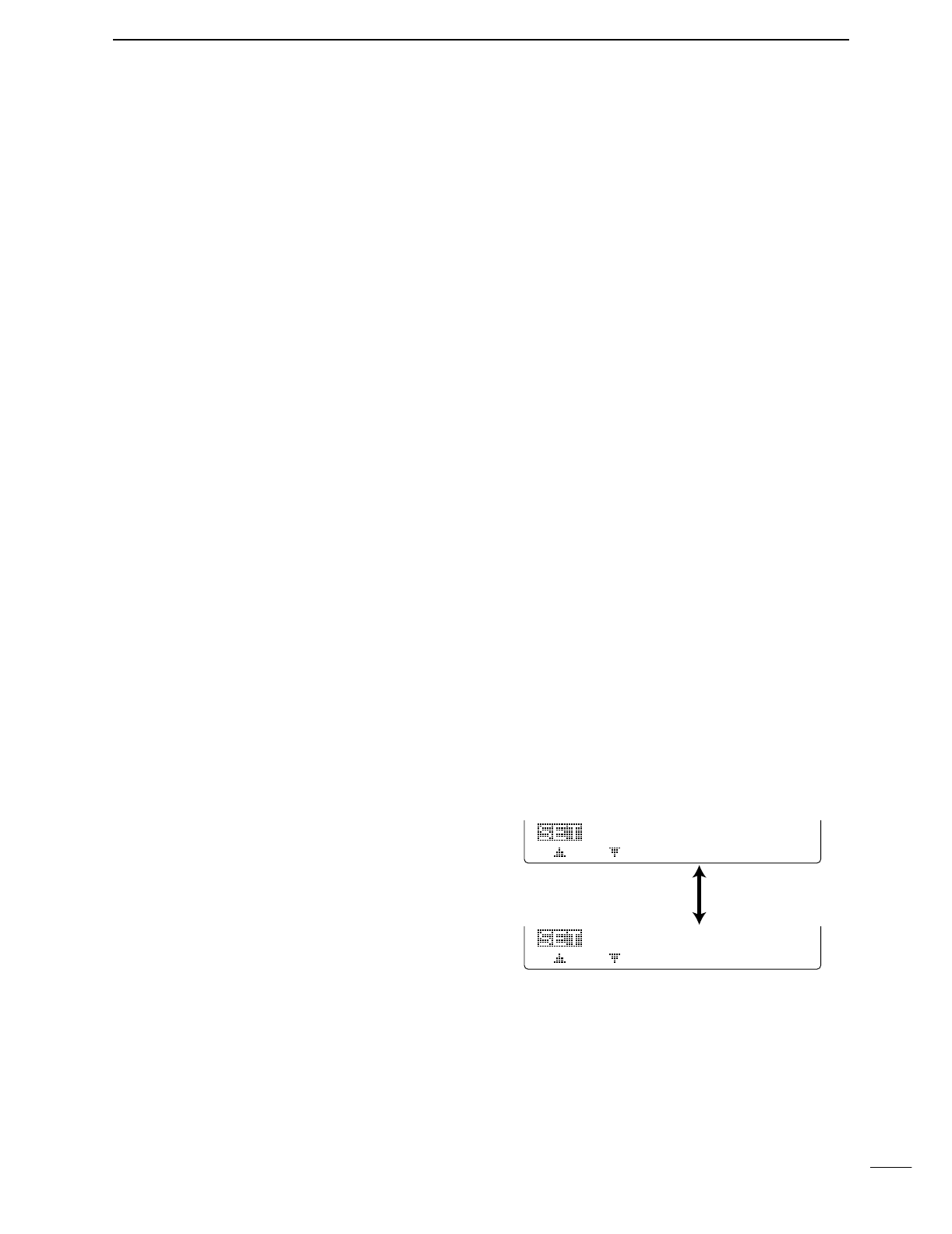
While the band scope is “sweeping,” “” appears; while stopped “” appears. Received
audio is not emitted from the speaker while the band scope is “sweeping.”
Indicates the relative strength of signals and their location in relation to the center (displayed)
frequency. Signal strength is relative to the S-meter level, S1 to S9, with each vertical dot in the
band scope indicator equal to one segment of the S-meter. Signal activity is measured ±30
steps from the center frequency with each step equal to the selected sweep step.
After a sweep, indicates the relative position of the selected frequency. When the selected fre-
quency is outside of the sweep range, indicator flashes. After changing the fre-
quency, push [F3] for 1 sec. to automatically return to the center frequency.
Indicates the selected sweep step. 0.5, 1, 2, 5, 10, 20 and 25 kHz are selectable. Each dot of
the band scope indication is approx. equal to the selected sweep step.
“ ” or “ ”
F 1 F 2 F 3 F 4 F 5
F 1 F 2 F 3 F 4 F 5
Sweep step selectionSweep start/stop
O.5k
STEP
O.5k
STEP
Sweep indicator
48
5
FUNCTIONS FOR RECEIVE
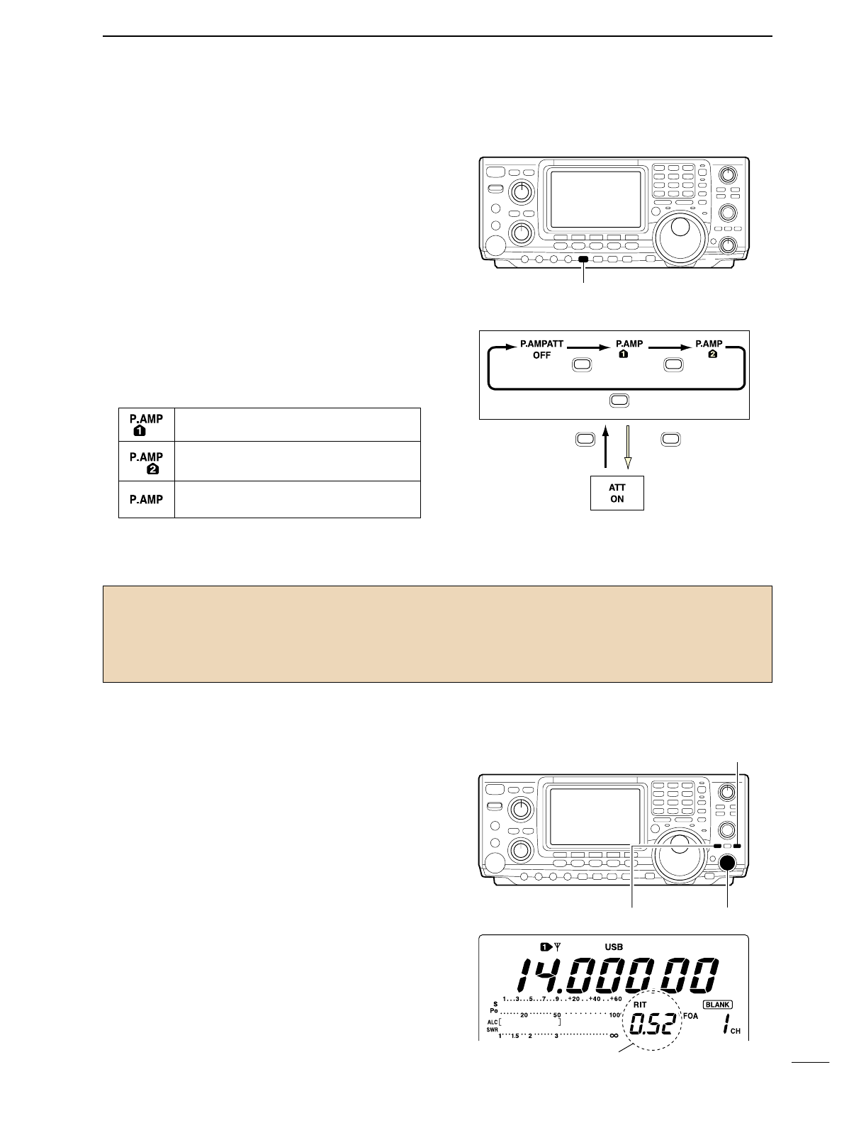
■Preamp/Attenuator
The preamp amplifies received signals in the front end
circuit to improve the S/N ratio and sensitivity. Set this
to preamp 1 or preamp 2 when receiving weak signals.
The attenuator prevents a desired signal from distor-
tion when very strong signals are near the desired fre-
quency or when very storing electric fields, such as
from broadcasting station, are near your location.
These can both set independently for each band.
➥Push [P.AMP/ATT] several times to set the preamp
OFF, preamp 1 ON or preamp 2 ON.
•When the preamp is ON, either “P.AMP 1” or
“P.AMP 2” appears in the function display.
•When operating on the 144 MHz band, the preamp can
only be set to ON or OFF only— there is no preamp 1
and preamp 2.
➥
Push [P.AMP/ATT] for 1 sec. to set the attenuator ON.
•
“ATT” appears ni the display when the function is set ON.
•Push [P.AMP/ATT] momentarily to set the attenuator OFF.
■RIT function
The RIT (Receive Increment Tuning) function compen-
sates for off-frequencies of the communicating station.
The function shifts the receive frequency up to
±9.99 kHz in 10 Hz steps without moving the transmit
frequency.
•See #0 on p. 4 for function description.
qPush [RIT] to turn the RIT function ON and OFF.
•“RIT” and the shifting frequency appear when the func-
tion is ON.
wRotate the [RIT/∂TX] control.
•Push [CLEAR] for 1 sec. to reset the RIT frequency.
•Push [CLEAR] momentarily to reset the RIT frequency
when the quick RIT/∂TX clear function is ON. (p. 85)
•Push [RIT] for 1 sec. to add the shift frequency to the op-
erating frequency.
DRIT monitor function
When the RIT function is ON, pushing and holding
[XFC] allows you to monitor the operating frequency
directly (RIT is temporarily cancelled).
[P.AMP/ATT]
Push
P.AMP/ATT
Push
P.AMP/ATT
Push
P.AMP/ATT
Push for 1sec.
P.AMP/ATT
Push
P.AMP/ATT
Regular preamp, the most effective for 1.8 to
21 MHz bands without IMD corruption.
High-gain preamp, the most effective for 24
to 50 MHz bands.
Preamp activates for the VHF band (144 to
146 MHz range; 108 to 174 for the USA version).
[RIT]
[CLEAR]
[RIT/∂TX] control
appear
Regarding the use of the “P.AMP 2”
The “P.AMP 2” is a high gain receive amplifier. When the
“P.AMP 2” is used during times of strong electric fields, dis-
tortion sometimes results. In such cases, use the trans-
ceiver with the “P.AMP 1” or “P.AMP OFF” setting.
The “P.AMP 2” is most effective when:
•Used on bands above 24 MHz and when electric fields are
weak.
•Receive sensitivity is insufficient during low gain, or while
using a narrow band antenna (such as small loop, a Bever-
age antenna or a short Yagi antenna, etc.) is used.
49
5FUNCTIONS FOR RECEIVE
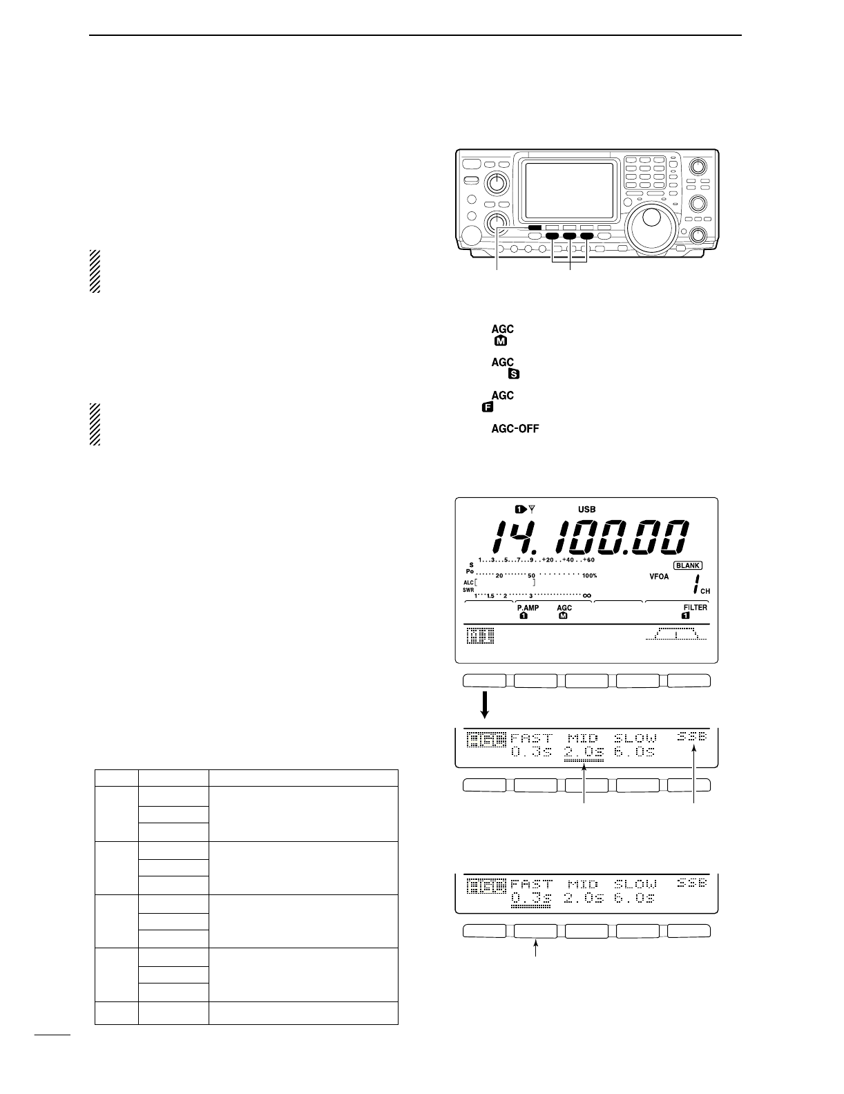
■AGC function
The AGC (auto gain control) controls receiver gain to
produce a constant audio output level even when the
received signal strength is varied by fading, etc.
The transceiver has 3 AGC characteristics (time con-
stant; fast, mid, slow) for non-FM mode.
The FM mode AGC time constant is fixed as ‘FAST’
(0.1 sec.) and AGC time constant cannot be se-
lected.
DAGC speed selection
qSelect non-FM mode.
wWhile M1 is selected, push [F1 AGC] several times
to select AGC F, AGC M, AGC Sor AGC OFF.
“AGC OFF” appears when AGC time constant OFF
is set with one of FAST, MID or SLOW setting in
AGC set mode.
DSetting the AGC time constant
qSelect the desired mode except FM mode.
wWhile M1 is selected, push [F1 AGC] for 1 sec. to
enter AGC set mode.
ePush one of [F2
FAST
], [F3
MID
] or [F4
SLOW
] to se-
lect the desired AGC speed to be set.
•Underline appears below the time constant indication.
rRotate the tuning dial to set the desired time con-
stant.
•AGC time constant can be set between 0.1 to 8.0 sec.
(depends on mode) or turned OFF.
•Push [F2
FAST
], [F3
MID
] or [F4
SLOW
] for 1 sec. to se-
lect a default value for each fast, mid. and slow, respec-
tively.
tSelect another mode except FM. Repeat steps e
and rif desired.
yPush [MENU] to exit the AGC set mode.
•Selectable AGC time constant (unit: sec.)
Mode Default Selectable AGC time constant
0.3 (FAST) OFF, 0.1, 0.2, 0.3, 0.5, 0.8, 1.2, 1.6
SSB 2.0 (MID) 2.0, 2.5, 3.0, 4.0, 5.0, 6.0
6.0 (SLOW)
0.1 (FAST) OFF, 0.1, 0.2, 0.3, 0.5, 0.8, 1.2, 1.6
CW 0.5 (MID) 2.0, 2.5, 3.0, 4.0, 5.0, 6.0
1.2 (SLOW)
0.1 (FAST) OFF, 0.1, 0.2, 0.3, 0.5, 0.8, 1.2, 1.6
RTTY 0.5 (MID) 2.0, 2.5, 3.0, 4.0, 5.0, 6.0
1.2 (SLOW)
3.0 (FAST) OFF, 0.3, 0.5, 0.8, 1.2, 1.6, 2.0, 2.5
AM 5.0 (MID) 3.0, 4.0, 5.0, 6.0, 7.0, 8.0
7.0 (SLOW)
FM 0.1 (FAST) Fixed
[F1 AGC] Mode switches
: Medium AGC speed
: Slow AGC speed
: Fast AGC speed
: AGC does not activated
F 1
F
2F
3
F
4
F
5
F 1
F
2 F
3
F
4
F
5
F 1 F 2 F 3 F 4 F 5
AGC
DUP
CMP
TBW
SCP
Push [F1] for 1 sec.
Selected modeAppears under the selected AGC
speed’s time constant indication.
Push [F2] for 1 sec. to select the default value in
this case.
• When AGC fast is selected
50
5
FUNCTIONS FOR RECEIVE
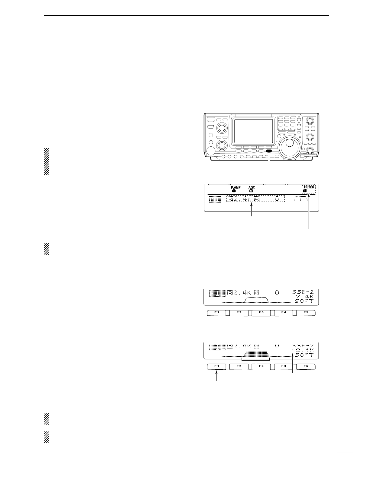
■IF filter selection
The transceiver has 3 passband width IF filters for
each mode.
For SSB and CW modes, the passband width can be
set within 50 to 3600 Hz in 50 or 100 Hz steps. A total
of 41 passband widths are available.
For RTTY mode, the passband width can be set within
50 to 2700 Hz in 50 or 100 Hz steps. A total of 32
passband widths are available.
For AM and FM modes, the passband width is fixed
and 3 passband widths are available independently.
The filter selection is automatically memorized in
each mode.
The PBT shift frequencies are automatically memo-
rized in each filter.
DIF filter selection
qSelect the desired mode.
wFor RTTY mode, turn OFF the RTTY filter.
ePush [FILTER] several times to select the IF filter
1, 2or 3.
•The selected passband width and filter number is dis-
played in the LCD.
By pushing [PBTC] indicate the set filter passband
width, “B,” and shifting value “S.”
DFilter passband width setting (SSB, CW and RTTY mode only)
qSelect SSB, CW or RTTY mode.
•Passband widths for AM and FM modes are fixed and
cannot be set.
wFor RTTY mode, turn OFF the RTTY filter.
ePush [FILTER] for 1 sec. to enter filter set mode.
rPush [FILTER] several times to select the desired
IF filter number.
tWhile pushing [F1 BW], rotate the tuning dial to set
the desired passband width.
•In SSB and CW modes, the passband width can be set
within the following range.
50 to 500 Hz 50 Hz steps
600 to 3600 Hz 100 Hz steps
•In RTTY mode, the passband width can be set within the
following range.
50 to 500 Hz 50 Hz steps
600 to 2700 Hz 100 Hz steps
•Push [F-3] for 1 sec. to select the default value.
yRepeat steps rto tif desired.
uPush [MENU] to exit the filter set mode.
The PBT shift frequencies are cleared when the
passband width is changed.
This filter set mode screen graphically displays the
PBT shift frequencies and CW pitch operations.
AGC
DUP
CMP
TBW
SCP
[FILTER]
The selected filter width is indicated
for approx. 1 sec. when [FILTER] is
pushed. Filter selection
BW
• Filter set mode indication
Shows the selected filter and passband width.
BW
• Indication while setting
While pushing [F1 BW], rotate the tuning dial to set
passband width.
Reverses Appears
51
5FUNCTIONS FOR RECEIVE
[NB]
NB
Level
5O%
Shows noise blanker level
“NB” appears while noise blanker is activated.
■IF (DSP) filter shape
The type of IF (DSP) filter shape for each SSB and
CW can be selected independently from soft and
sharp.
qPush [SSB] or [CW/RTTY] to select SSB, CW or
RTTY mode.
wSelect the filter set mode.
•Push [FILTER] for 1 sec.
•Operating mode can be selected in this step.
ePush [FILTER] several times to select the desired
IF filter.
rPush the [F5] to select the filter shape from “
SOFT
”
and “
SHARP
.”
tPush [MENU] to exit the set mode.
■Noise blanker
The noise blanker eliminates pulse-type noise such as
from car ignitions. The noise blanker is not available
for FM mode.
qPush [NB] to turn the noise blanker ON.
•[NB] indicator appears.
wPush [NB] for 1 sec. to enter the NB level set mode.
eRotate the tuning dial to adjust the noise blanker
level.
•Noise blanker level is indicated with bar meter and digit
in ‘%.’
rPush [NB] to exit the noise blanker set mode.
tPush [NB] to turn the noise blanker OFF.
•[NB] indicator disappears.
When using the noise blanker, received signals may
be distorted if they are excessively strong.
■Meter peak hold function
The S-meter shows the peak level holding function.
Peak level of receiving signal strength is indicated for
0.5 sec. (approx.). This function can be deactivated in
the set mode if desired. (p. 81)
BW
BW
Push [F5]
Meter
Peak
Hold
9
ON
Shows peak level for approx. 0.5 sec.
52
5
FUNCTIONS FOR RECEIVE
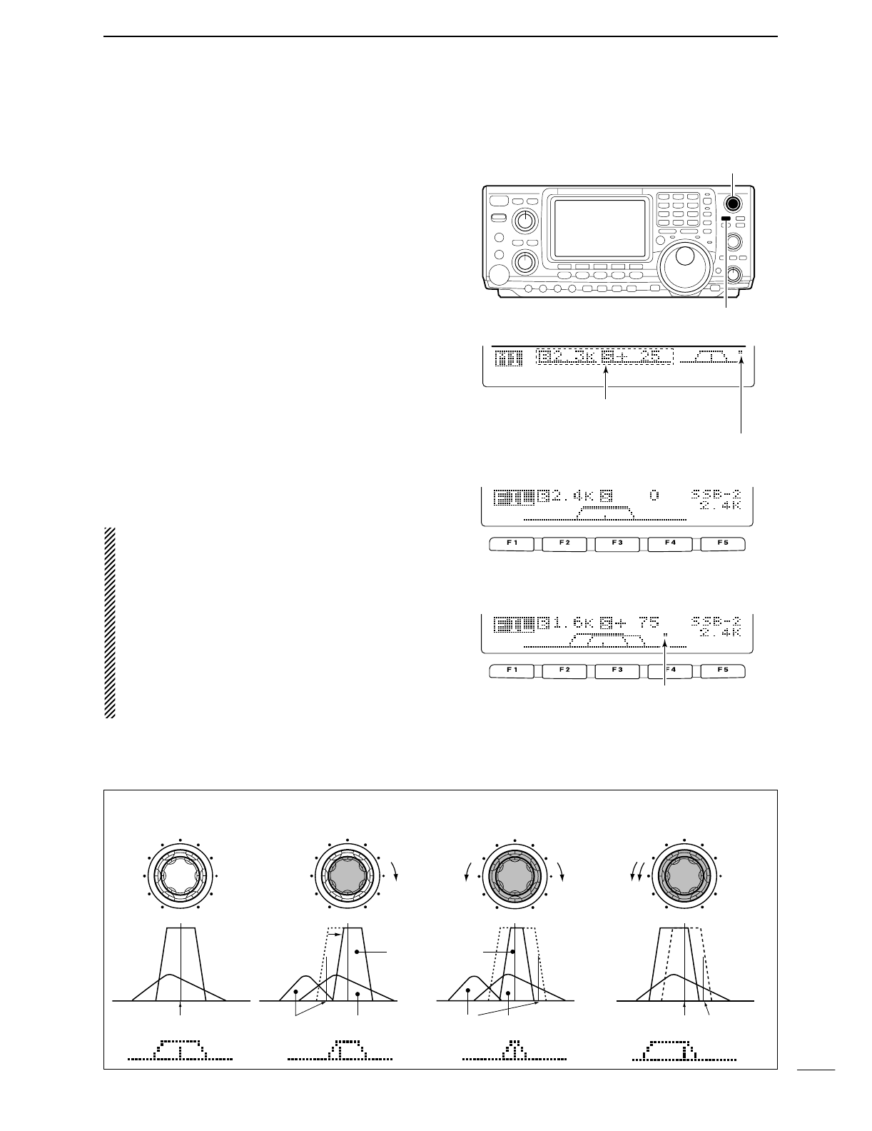
■Twin PBT operation
General PBT (Passband Tuning) function electronically
narrows the IF passband width by shifting the IF fre-
quency to slightly outside of the IF filter passband to
reject interference. This transceiver uses the DSP cir-
cuit for the PBT function. Moving both [TWIN PBT]
controls to the same position shifts the IF.
➥The LCD shows the passband width and shift fre-
quency graphically.
➥Push [FILTER] for 1 sec. to enter the filter set mode.
Current passband width and shift frequency is dis-
played in the filter set mode screen.
➥To set the [TWIN PBT] controls to the center posi-
tions, push [PBTC] for 1 sec.
The variable range depends on the passband width
and mode. The edge of the variable range is half of the
passband width, and PBT is adjustable in 25 or 50 Hz
steps. These controls function as an IF shift control
while in AM mode and when the RTTY filter is turned
ON. Only the inner control may function in this case.
IF shift is adjustable in 20/40 Hz steps in RTTY (RTTY
filter is turned ON) or 150/300/500 Hz steps in AM.
•[TWIN PBT] should normally be set to the center posi-
tions (PBT setting is cleared) when there is no interfer-
ence.
•When PBT is used, the audio tone may be changed.
•Not available for FM mode.
•For AM and RTTY (with RTTY filter ON) modes,
[TWIN PBT] inner control can only be activated, and
functions as an IF shift function.
•While rotating [TWIN PBT], noise may occur. This comes
from the DSP unit and does not indicate an equipment
malfunction.
•By pushing [PBTC] momentarily, indicate the using filter
passband width, “B,” and shifting value, “S.”
PBT OPERATION EXAMPLE
interference
inteference
interference desired signal
desired signal
pass band
IF center frequency
Center Passband Passband
IF center freq.
IF shift
AGC
DUP
CMP
TBW
SCP
Passband width and shifting value are
indicated while [TWIN PBT] is operated.
[TWIN PBT] control
[PBTC]
Appears when PBT is used.
BW
• Filter set mode indication
Shows the selected filter and passband width.
BW
• Indication while PBT setting
Appears when passband is shifted.
*Pushing [PBTC] for 1 sec., the shifted value
return to default setting and the “dot” disappears.
53
5FUNCTIONS FOR RECEIVE
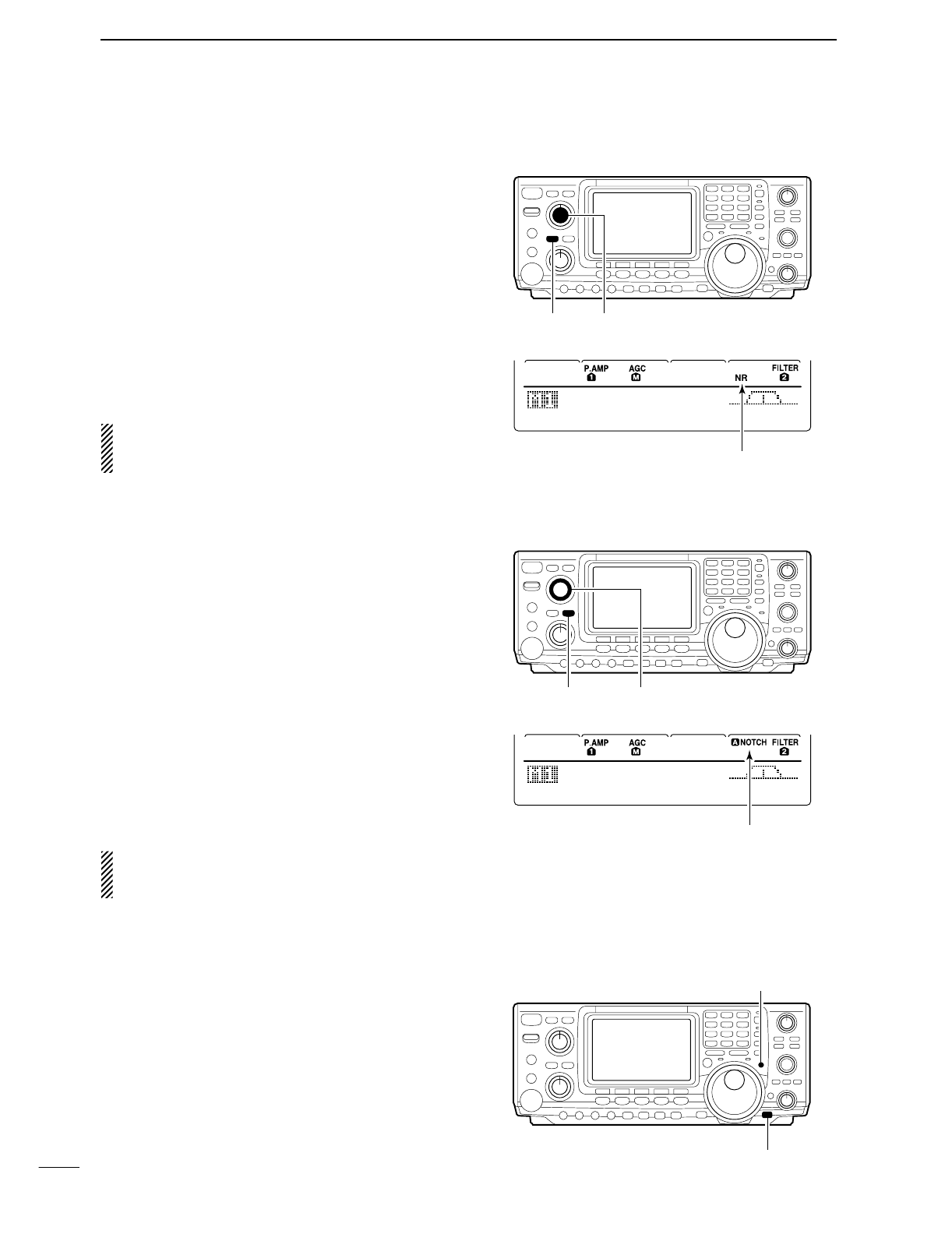
■Noise reduction
The noise reduction function reduces noise compo-
nents and picks out desired signals which are buried
in noise. The received signals are converted to digital
signals and then the desired signals are separated
from the noise.
qPush the [NR] switch to turn the noise reduction
ON.
•“NR” appears.
wRotate the [NR] control to adjust the noise reduction
level.
ePush the [NR] switch to turn the noise reduction
OFF.
•“NR” disappears.
Deep rotation of the [NR] control results in audio sig-
nal masking or distortion. Set the [NR] control for
maximum readability.
■Notch function
This transceiver has auto and manual notch functions.
The auto notch function automatically attenuates more
than 3 beat tones, tuning signals, etc., even if they are
moving. The manual notch can be set to attenuate a
frequency via the [NOTCH] control.
➥Push [A/NOTCH] to toggle the notch function be-
tween auto, manual and OFF in SSB and AM
modes.
➥Push [A/NOTCH] to turn the manual notch function
ON and OFF in CW mode.
➥Push [A/NOTCH] to turn the auto notch function ON
and OFF in FM mode.
•Set to attenuate a frequency for manual notch via the
[NOTCH] control.
•“ANOTCH” appears when auto notch is in use.
•“NOTCH” appears when manual notch is in use.
While operating the manual notch, noise may be
heard. This comes from the DSP unit and does not
indicate an equipment malfunction.
■Dial lock function
The dial lock function prevents accidental changes
caused by the tuning dial.
➥Push [LOCK/SPCH] to turn the dial lock function ON
and OFF.
•“LOCK” indicator lights while the dial lock function is ac-
tivated.
AGC
DUP
CMP
TBW
SCP
[A/NOTCH] [NOTCH]
Notch function indicators
AGC
DUP
CMP
TBW
SCP
[NR] [NR]
Appears
[LOCK/SPCH]
Lights while the dial lock function is activated.
54
5
FUNCTIONS FOR RECEIVE
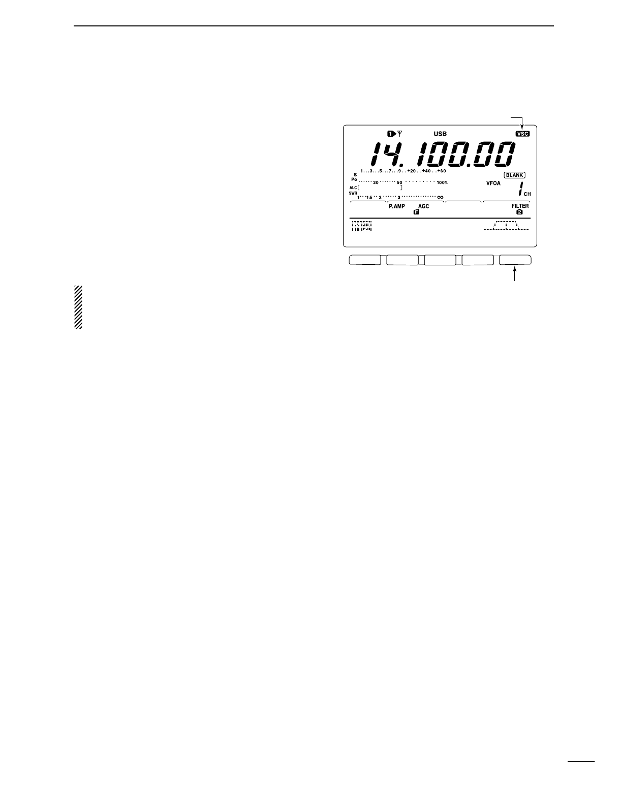
■Voice squelch control function
This function is useful when you don’t want unmodu-
lated signals. When the voice squelch control function
is activated, the receiver checks received signals for
voice components.
If a receiver signal includes voice components, and the
tone of the voice components changes within 1 sec.,
squelch opens. If the received signal includes no voice
components or the tone of the voice components does
not change within 1 sec., squelch closes.
➥While M2 is selected with [MENU], push [F5 VSC]
to switch the VSC (Voice Squelch Control) function
ON and OFF.
•“VSC” appears when the function is activated.
•The VSC function activates for phone modes
(SSB, AM and FM).
•The VSC function can also be used for scanning
operation in AM or FM mode (p. 00).
F 1 F 2 F 3 F 4 F 5
SCN
MEM
SWR
TCN
VSC
Push [F5] to turn the VSC function ON and OFF.
VSC indicator
6
55
FUNCTIONS FOR TRANSMIT
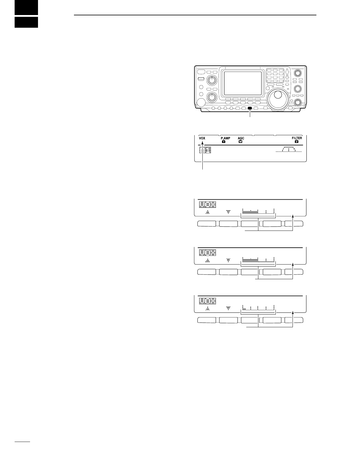
■VOX function
The VOX (Voice-Operated Transmission) function
switches between transmit and receive with your voice.
This function provides an opportunity to input log en-
tries into your computer, etc., while operating.
•Using the VOX function
qSelect a phone mode (SSB, AM, FM).
wPush [VOX/BK-IN] to turn the VOX function ON or
OFF.
DAdjusting the VOX function
qSelect a phone mode (SSB, AM, FM).
wPush [VOX/BK-IN] to turn VOX function ON.
ePush [VOX/BK-IN] for 1 sec. to enter VOX set
mode.
rSelect the VOX Gain item using [F1 ≤] or [F2 ≥].
tWhile speaking into the microphone, rotate the tun-
ing dial to the point where the transceiver is contin-
uously transmitting.
-Pushing [F3] for 1 sec. to select the default value.
yPush [F2 ≥] to select Anti-VOX item.
uWhile receiving, rotate the tuning dial to the point
where the transceiver does not switch to transmit
with the speaker output.
-Pushing [F3] for 1 sec. to select the default value.
yPush [F2 ≥] to select VOX Delay item.
yAdjust the VOX delay for a convenient interval be-
fore returning to receive.
-Select the VOX delay item using the tuning dial.
-Pushing [F3] to select the default value.
uPush [MENU] to return to previous indication.
AGC
DUP
CMP
TBW
SCP
[VOX/BK-IN]
Appears
F 1 F 2 F 3 F 4 F 5
F 1 F 2 F 3 F 4 F 5
F 1 F 2 F 3 F 4 F 5
VOX
Gain
5O%
Shows VOX gain level
1
Anti-VOX
5O%
Shows anti-VOX gain level
2
VOX
Delay
O.2s
Shows VOX delay time
3
56
6
FUNCTIONS FOR TRANSMIT
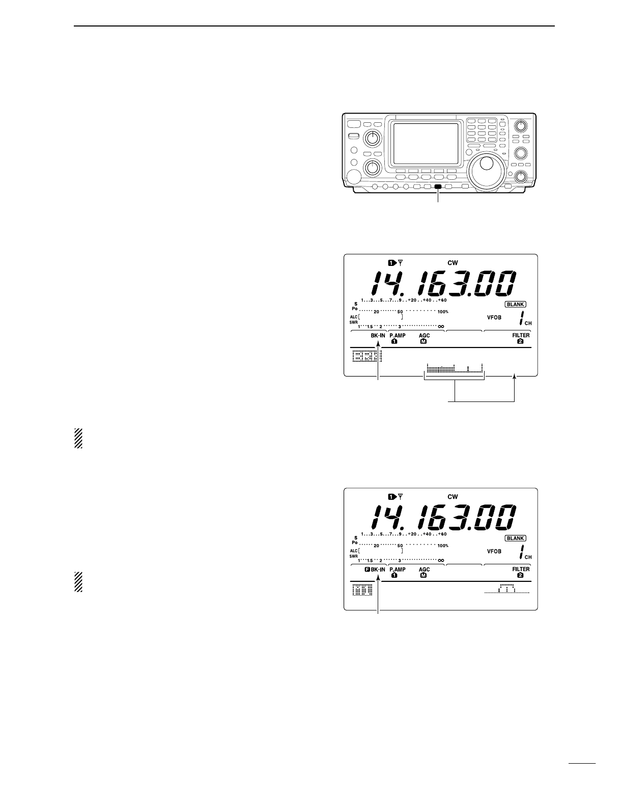
■Break-in function
The break-in function is used in CW mode to automat-
ically toggle the transceiver between transmit and re-
ceive when keying. The IC-746PRO is capable for full
break-in or semi break-in.
DSemi break-in operation
During semi break-in operation, the transceiver selects
transceive when keying, then automatically returns to
receive after a pre-set time from when you stop keying.
qPush [CW/RTTY] to select CW or CW-R mode.
wPush [VOX/BK-IN] several times to turn the semi
break-in function ON.
•“BK-IN” appears.
eSet the break-in delay time (the delay from transmit
to receive).
➥Push [VOX/BK-IN] for 1 sec. to select break-in
delay program mode.
➥Rotate the tuning dial to select the desired delay.
•Push [F3] for 1 sec. to select to the default value.
rPush [MENU] to return to the previous menu.
When using a paddle, rotate [KEY SPEED] to adjust
the keying speed.
DFull break-in operation
During full break-in operation, the transceiver automati-
cally selects receive if a signal is detected while keying.
qPush [CW/RTTY] to select CW or CW-R mode.
wPush [VOX/BK-IN] several times to turn the full
break-in function ON.
•“FBK-IN” appears.
When using a paddle, rotate [KEY SPEED] to adjust
the keying speed.
[VOX/BK-IN]
Break-IN
Delay
Break-in indicator
Shows break-in delay time
7.5d
AGC
DUP
1/4
KEY
SCP
Full break-in indicator
57
6FUNCTIONS FOR TRANSMIT
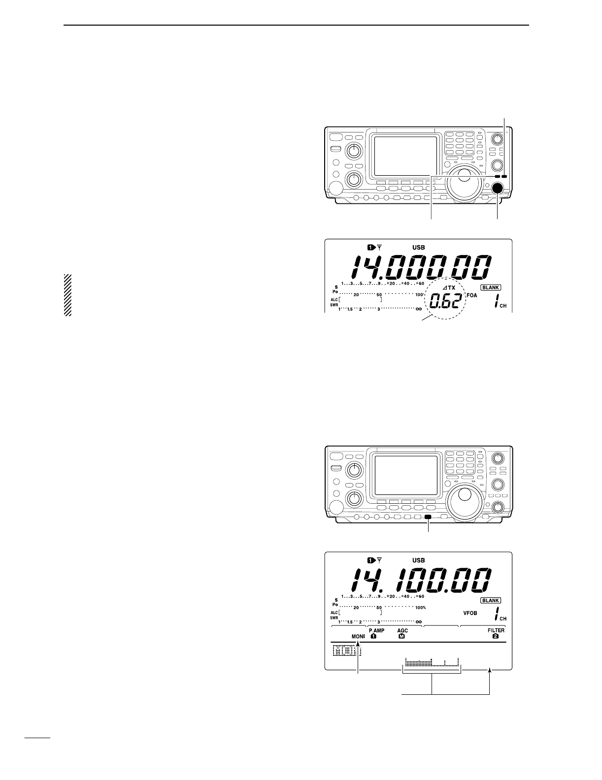
■∂TX function
The ∂TX function shifts the transmit frequency up to
±9.99 kHz in 10 Hz steps without moving the receive
frequency.
•See #2 on p. 4 for function description.
qPush the [∂TX] switch to turn the ∂TX function ON
and OFF.
•“∂TX” and shift frequency appear when the function is
ON.
wRotate the [RIT/∂TX] control.
•To reset the ∂TX frequency, push [CLEAR] for 1 sec.
•Push [CLEAR] momentarily to reset the RIT frequency
when the quick RIT/∂TX clear function is ON. (p. 00)
•To add or subtract the ∂TX frequency to the displayed
frequency, push [∂TX] for 1 sec.
When RIT and ∂TX are ON at the same time, the
[RIT/∂TX] control shifts both the transmit and re-
ceive frequencies from the displayed frequency at
the same time.
D∂TX monitor function
When the ∂TX function is ON, pushing and holding
[XFC] allows you to monitor the operating frequency di-
rectly (∂TX is temporarily cancelled).
■Monitor function
The monitor function allows you to monitor your trans-
mit IF signals in any mode through the speaker. Use
this to check voice characteristics while adjusting SSB
transmit tones. (p. 88) The CW sidetone functions re-
gardless of the [MONITOR] switch setting.
qPush [MONITOR] to switch the monitor function ON
and OFF.
•“MONI” appears when the monitor function is ON.
wSet the monitor level.
➥Push [MONITOR] for 1 sec. to select monitor pro-
gram mode.
➥Rotate the tuning dial for the clearest audio out-
put while pushing [PTT] and speaking into the mi-
crophone.
•Push [F3] for 1 sec. to select the default value.
rPush [MENU] to return to the previous menu.
[∂TX]
[CLEAR]
[RIT/∂TX] control
appear
[MONITOR]
MONITOR
Level
Monitor indicator
Shows monitor level
5O%
58
6
FUNCTIONS FOR TRANSMIT
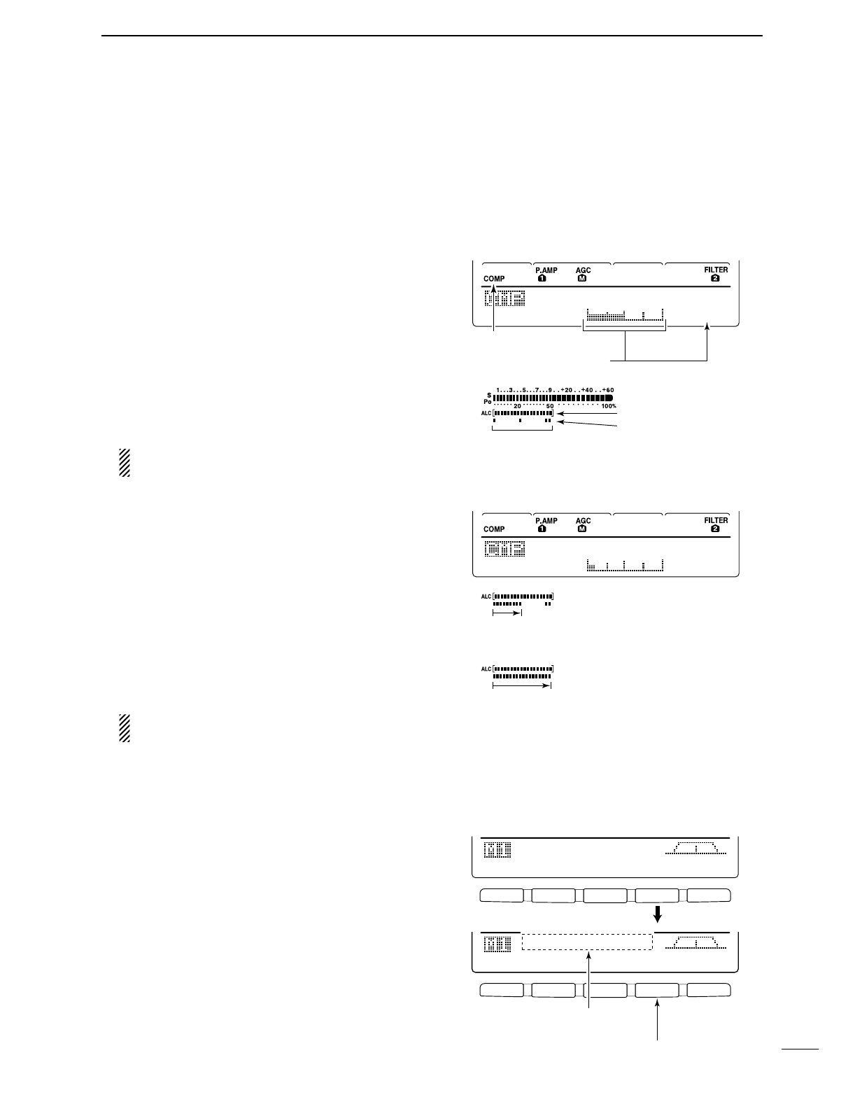
■Speech compressor
The speech compressor increases average RF output
power, improving signal strength and readability in
SSB, AM or FM.
When adjusting the compression level, it is necessary
to turn the COMP meter ON in the set mode, in ad-
vance (p. 81).
•In SSB mode
qSelect USB or LSB mode and adjust [MIC GAIN] to
a suitable level.
wWhile M1 is selected, push [F3 CMP] to turn the
speech compressor ON.
•“COMP” appears.
ePush [F3 CMP] for 1 sec. to select compression
level set mode.
rWhile speaking into the microphone, rotate the tun-
ing dial, so that the COMP meter reads within the
COMP zone with your normal voice level.
•Push [F3] for 1 sec. to select the default value.
When the COMP meter peaks above the COMP
zone, your transmitted voice may be distorted.
tPush [MENU] to return to M1.
•In AM/FM mode
qWhile M1 is selected, push [F3 CMP] to turn the
speech compressor ON.
•“COMP” appears.
wPush [F3 CMP] for 1 sec. and set the compression
level as “1” in advance.
eWhile speaking into the microphone, rotate [MIC
GAIN], so that the COMP meter does not exceeds
the center dot whether you speak softly or loudly.
rWhile speaking into the microphone, rotate the tun-
ing dial, so that the COMP meter reads within the
COMP zone with your normal voice level.
•Push [F3] for 1 sec. to select the default value.
When the COMP meter peaks above the COMP
zone, your transmitted voice may be distorted.
tPush [MENU] to return to M1.
■
Transmit filter width selection
(SSB mode only)
The transmit filter width for SSB mode can be selected
from wide, middle and narrow.
qSelect USB or LSB mode.
wPush [MENU] to select M1, if necessary.
ePush [F4 TBW] for 1 sec. to select the transmission
passband width.
•One of “TX BW=WIDE,” “TX BW=MID” or “TX
BW=NAR” is displayed for approx. 1 sec.
•Transmit filter width: NAR 2.0 kHz
MID 2.6 kHz
WIDE 2.9 kHz
COMP
Level
COMP
Level
5
1
Compressor indicator
Shows compression level
COMP level zone
*The SWR meter functions as the COMP meter
when COMP meter is set to ON in the set mode.
COMP meter
ALC meter
Adjust the COMP Level with the tuning dial so
that the COMP meter does not exceeds the COMP
level zone.
Adjust [MIC GAIN], so that the COMP meter does
not exceeds this zone.
F 1
F
2F
3
F
4
F
5
F 1 F 2 F 3 F 4 F 5
AGC
DUP
CMP
TBW
SCP
AGC
DUP
CMP
TBW
SCP
TX
BW=WIDE
Push [F4]
Push [F4] for 1 sec. to select the transmit filter width.
The selected transmit filter width
is displayed for approx. 1 sec.
59
6FUNCTIONS FOR TRANSMIT
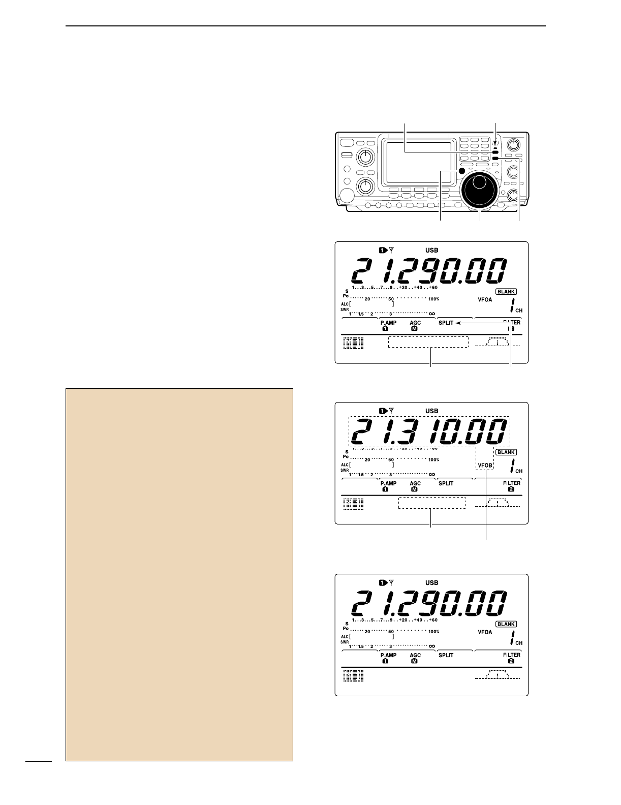
■Split frequency operation
Split frequency operation allows you to transmit and
receive in the same mode on two different frequencies.
The split frequency operation is basically performed
using 2 frequencies in VFO A and VFO B.
The following is an example of setting 21.290 MHz for
receiving and 21.310 MHz for transmitting.
qSet 21.290 MHz (USB) in VFO A.
wPush [SPLIT] to turn the split function ON, then
push [A/B] for 1 sec.
•The equalized transmit (VFO B) frequency and “SPLIT”
appear on the LCD, and the [SPLIT] indicator lights.
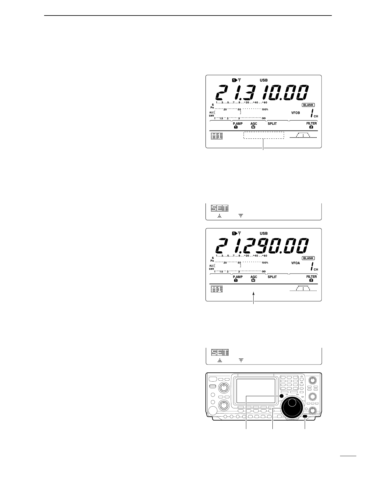
eWhile pushing [XFC] rotate the tuning dial to set the
transmit frequency to 21.310 MHz.
•The transmit frequency can be monitored while pushing
[XFC].
rNow you can receive on 21.290 MHz and transmit
on 21.310 MHz.
To change the transmit and receive frequencies, push
[A/B] to exchange the VFO A and VFO B.
Tuning dial[XFC]
[SPLIT] Lights during split operation
[A/B]
AppearsShows transmit (VFO B) frequency
AGC
DUP
CMP
TBW
SCP
21.29OOO
Shows transmit (VFO B) frequency
Shows shift frequency and direction
AGC
DUP
CMP
TBW
SCP
+2O.OOk
• While pushing [XFC]
AGC
DUP
CMP
TBW
SCP
21.31OOO
• After setting up
CONVENIENT
•Direct shift frequency input
The shift frequency can be entered directly.
qPush [F-INP].
wEnter the desired shift frequency with the digit
keys.
•1 kHz to 1 MHz can be set.
•When you require a minus shift direction, push
[GENE •] in advance.
ePush [SPLIT].
•The shift frequency is input in the sub readout and the
split function is turned ON.
[Example]
To transmit on 1 kHz higher frequency:
- Push [F-INP], [1.8
1
] then [SPLIT].
To transmit on 3 kHz lower frequency:
- Push [F-INP], [GENE • ], [7
3
] then [SPLIT].
•Split lock function
Accidentally releasing the [XFC] switch while rotating
the tuning dial changes the receive frequency. To pre-
vent this, use both the split lock and dial lock func-
tions to change the transmit frequency only. The split
lock function cancels the dial lock function while
pushing [XFC] during split frequency operation.
The dial lock’s effectiveness during split frequency
operation can be selected in the set mode for both
receive and transmit frequencies; or only the receive
frequency. (p. 82)
60
6
FUNCTIONS FOR TRANSMIT
■Quick split function
When you push the [SPLIT] switch for 1 sec., split fre-
quency operation is turned ON, the un-displayed VFO
is automatically changed according to the plus/minus
shift frequency programmed in set mode (p. 82) or
equalized when 0 kHz (default value) is programmed
as the split shift frequency. Quick split operation is
turned ON by default but can be turned OFF in set
mode (p. 82).
qSuppose you are operating at 21.290 MHz (USB) in
VFO A.
wPush [SPLIT] for 1 sec.
•Split frequency operation is turned ON.
•The VFO and VFO B are equalized.
eWhile pushing [XFC], rotate the tuning dial to set
the frequency offset between transmit and receive.
•When [XFC] is released, the receive frequency is indi-
cated.
DSplit offset frequency setting
By setting an often-used split frequency offset in ad-
vance, you can use the quick split function to select split
operation at the push of one switch.
Set the split offset frequency in advance in set mode
(p. 82, item 12). The example at right shows the split
offset is set to +0.020 MHz.
➥Push [SPLIT] for 1 sec. to activate the quick split
function.
•The transmit frequency is offset from the receive fre-
quency according to the offset in set mode.
DSplit lock function
The split lock function is convenient for changing only
the transmit frequency. When the split lock function is
not used, accidentally releasing [XFC] while rotating the
tuning dial, changes the receive frequency. The split
lock function is ON by default, but can be turned OFF
in set mode.
qWhile split frequency operation is ON, push
[LOCK/SPCH] to activate the split lock function.
wWhile pushing [XFC], rotate the tuning dial to
change the transmit frequency.
•If you accidentally release [XFC] while rotating the tuning
dial, the receive frequency does NOT change.
Shows shift frequency and direction
AGC
DUP
CMP
TBW
SCP
+2O.OOk
• Setting the frqeuency while pushing [XFC]
AGC
DUP
CMP
TBW
SCP
21.31OOO
12
+O.O2OMHz
SPLIT
Offset
Shows transmit frqeuency for split operation
13
OFF
SPLIT
LOCK
[XFC] Tuning dial [LOCK/SPCH]
61
6FUNCTIONS FOR TRANSMIT
■Measuring SWR
The IC-746PRO has a built-in circuit for measuring an-
tenna SWR— no external equipment or special adjust-
ments are necessary.
The IC-746PRO can measure SWR in 2 ways— spot
measurement and plot measurement are available.
DSpot measurement
qPush [TUNER] to turn the antenna tuner OFF.
wTurn the COMP meter OFF.
•Push [MENU] for 1 sec. to enter set mode.
•Push [F1 ≤] or [F2 ≥] several times to select the COMP
Meter item.
•Rotate the tuning dial to set the COMP meter OFF.
•Push [MENU] to exit set mode.
ePush [CW/RTTY] several times to select RTTY
mode.
rPush [TRANSMIT] or [PTT] of the microphone.
tRotate [RF PWR] clockwise past the 12 o’clock po-
sition for more than 30 W output power (30%).
yRead the SWR on the SWR meter.
uPush [TRANSMIT] or release [PTT] to receive.
The built-in antenna tuner matches the transmitter
to the antenna when the SWR is lower than 3:1.
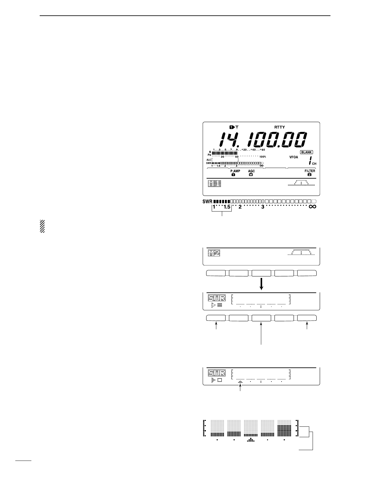
DPlot measurement
Plot measurement allows you to measure the SWR
over an entire band.
qWhile M2 is selected with [MENU], push [F3 SWR].
•SWR graph screen appears.
wRotate [RF PWR] clockwise past the 12 o’clock po-
sition for more than 30 W output power (30%).
eSet the center frequency for the SWR to be mea-
sured.
rPush [F5] for 1 sec. several times to select the de-
sired measuring step from 10, 50, 100 and 500 kHz.
tPush [F3] several times to select the desired num-
ber of measuring steps from 3, 5, 7, 9, 11 and 13
steps.
yPush [F1] to start the measuring.
uPush [TRANSMIT] or push and hold [PTT] of the
microphone to measure the SWR.
•Frequency marker, “∫,” appears below SWR graph.
•RTTY mode is automatically selected.
iWhen pushing [TRANSMIT] again or release [PTT],
the frequency marker and frequency indication
move to the next frequency to be measured.
oRepeat steps uand ito measure SWR over the
entire frequency range.
!0 When the measured SWR is less than 1.5:1, the
antenna is well matched with the transceiver in the
measured frequency range.
AGC
DUP
1/4
RTY
SCP
The best match is in this range.
F 1
F
2F
3
F
4
F
5
F 1 F 2 F 3 F 4 F 5
SCN
MEM
SWR
TCN
VSC
1Ok
STEP
1Ok
STEP
Push [F3]
Push [F5] to select
SWR measuring step.
Push [F3] to select number of SWR measuring steps.
Push [F1] to start
measuring.
• Measuring (after pushing [F1])
Frequency marker appears and moves after meas-
urement.
*When mesurement point/s is/are set outside of the oper-
atable frequency band, frequency marker flashes.
Typical display SWR varying between 1 and 2,
full scale up to SWR 4.0:1.
— 1.0:1
— 1.5:1
— 2.0:1
— 3.0:1
— 4.0:1
7
62
MEMORY OPERATION
■Memory channels
The transceiver has 101 memory channels (plus 1 call
channel). The memory mode is very useful for quickly
changing to often-used frequencies.
All 101 memory channels are tuneable which means
the programmed frequency can be tuned temporarily
with the tuning dial, etc. in memory mode.
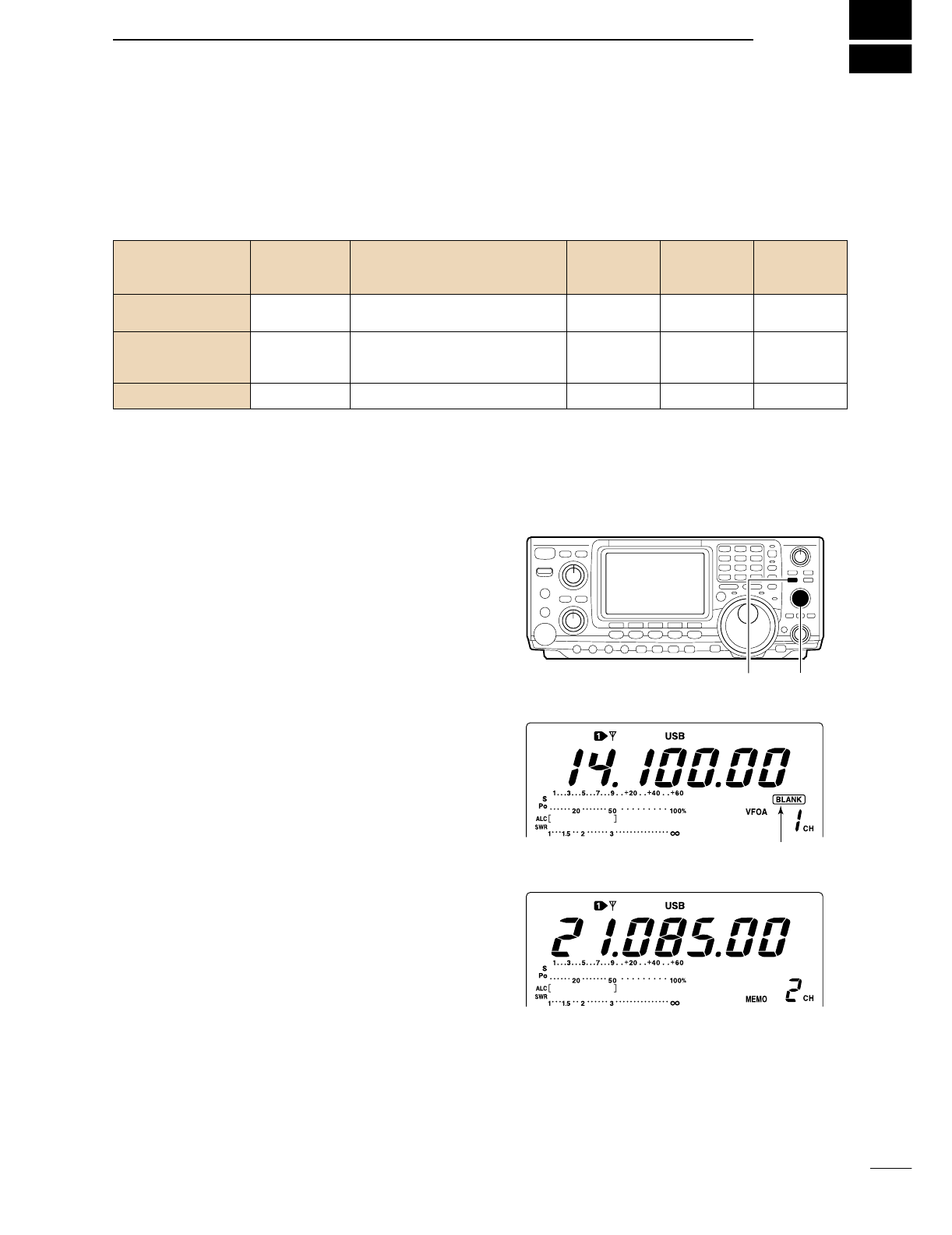
■Memory channel selection
DIn VFO mode
qPush [V/M] to select VFO mode, if necessary, then
rotate [M-CH] to select a memory channel number.
•All memory channels including blank channels can be
selected.
•“BLANK” appears when no information has been pro-
grammed into a memory channel.
wPush [V/M] to select memory mode.
•“MEMO” and contents of the memory channel appear.
DIn memory mode
qPush [V/M] to select memory mode.
wRotate [M-CH] to select a memory channel.
•All memory channels including blank channels can be
selected.
•Memory channels can also be selected using the micro-
phone [UP]/[DN] keys.
[V/M][M-CH]
Disappears when a channel is programmed.
• During VFO mode
• During memory mode
MEMORY MEMORY TRANSFER OVER-
CHANNEL CHANNEL CAPABILITY TO VFO WRITING CLEAR
NUMBER
Regular memory 1–99 One frequency and one mode Yes Yes Yes
channels in each memory channel.
Scan edge
One frequency and one mode in
memory P1, P2 each memory channel as scan Yes Yes No
channels edges for programmed scan.
Call channel C Same as regular. No Yes No
63
7MEMORY OPERATION
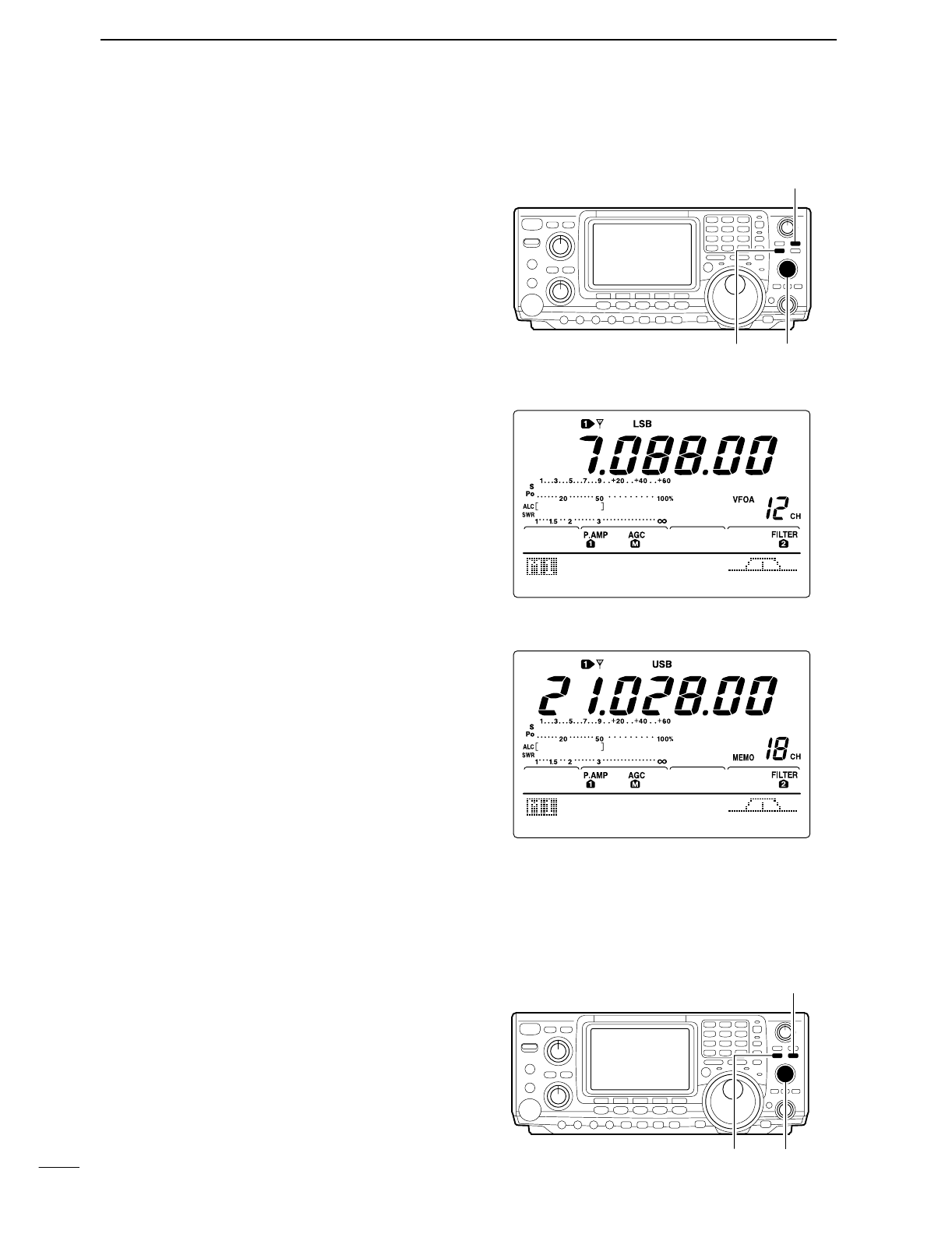
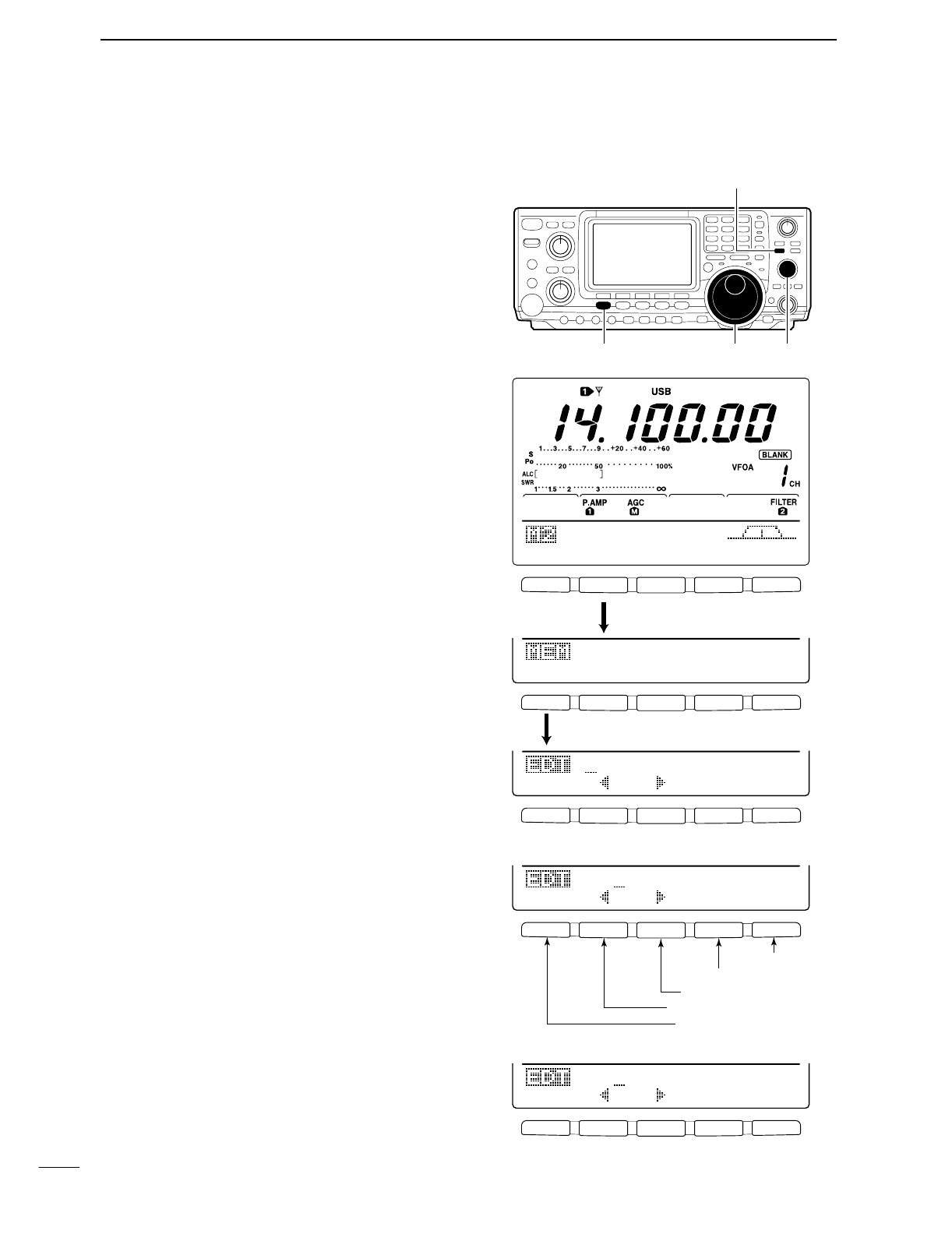
■Programming a memory
Memory channel programming can be preformed ei-
ther in VFO mode or in memory mode.
DProgramming in VFO mode
qSet the desired frequency and operating mode in
VFO mode.
wRotate [M-CH] to select the desired memory chan-
nel.
•“BLANK” appears if the selected memory channel is a
blank channel (and does not have contents).
ePush [MW] for 1 sec. to program the displayed fre-
quency and operating mode into the memory chan-
nel.
•3 beeps are emitted when memory programming is suc-
cessful.
DProgramming in VFO mode
qSelect the desired memory channel with [M-CH] in
memory mode.
•Memory channel contents appear in the display.
•“BLANK” appears and no frequency readout is displayed
if the selected memory channel is a blank channel (and
does not have contents).
wSet the desired frequency and operating mode in
memory mode.
•To program a blank channel, use direct frequency entry
with the keypad or memo pads, etc.
ePush [MW] for 1 sec. to program the displayed fre-
quency and operating mode into the memory chan-
nel.
•3 beeps are emitted when memory programming is suc-
cessful.
■Memory clearing
Any unnecessary memory channels can be cleared.
The cleared memory channels become blank chan-
nels.
qSelect memory mode with [V/M].
wSelect the desired memory channel with [M-CH].
ePush [M-CL] for 1 sec. to clear the contents.
•The programmed frequency and operating mode disap-
pear.
•3 beeps are emitted when memory clearing is success-
ful.
rTo clear other memory channels, repeat steps w
and e.
[V/M][M-CH]
[MW]
AGC
DUP
CMP
TBW
SCP
• [EXAMPLE]: Programming 7.088 MHz/LSB
into memory channel 12.
AGC
DUP
CMP
TBW
SCP
• [EXAMPLE]: Programming 21.280 MHz/USB
into memory channel 18.
[V/M][M-CH]
[M-CL]
64
7
MEMORY OPERATION
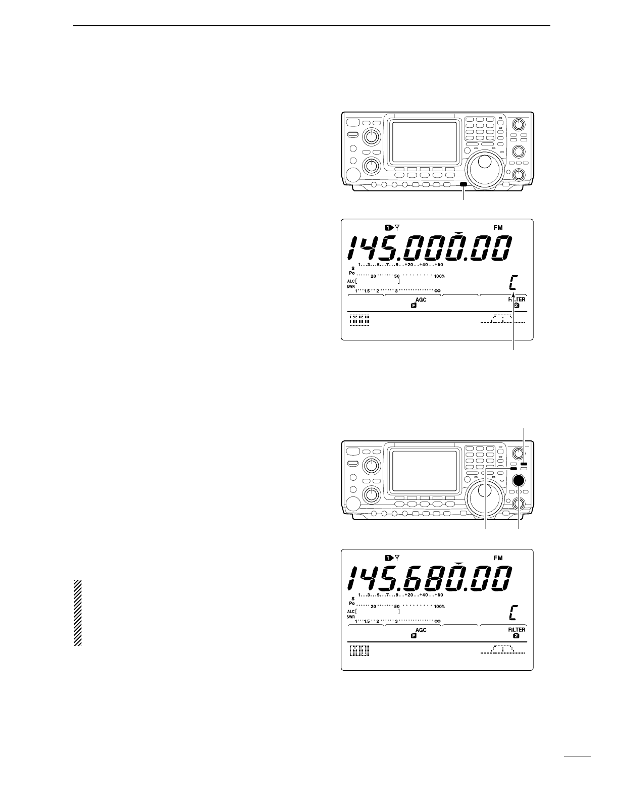
■Selecting the call channel
By default 145.00000 MHz/FM is programmed into the
call channel. However, this can be changed to suit
your operating preference. (see below)
qPush [CALL] to select the call channel.
•“C” appears.
wPush [CALL] again to return to the previous mode.
■
Programming the call channel
The call channel is programmed in the same way reg-
ular memory channels are. It’s convenient to program
a most-often-used frequency into the call channel for
quick recall. As with memory channels, the call chan-
nel can also hold split frequencies.
qRotate [M-CH] to select the call channel.
•“C” appears.
wSelect the desired frequency and operating mode
to program into the call channel.
ePush [MW] for 1 sec. to program the displayed fre-
quency and operating mode into the call channel.
•3 beeps are emitted when memory programming is suc-
cessful.
IMPORTANT!: When the call channel is selected
with the [CALL] switch, the frequency CANNOT be
changed using the tuning dial, band keys or keypad
input. However, when the call channel is selected
using [M-CH] in memory mode, the frequency CAN
be changed.
[CALL]
AGC
DUP
CMP
TON
SCP
“C” appears
[V/M][M-CH]
[MW]
AGC
DUP
CMP
TON
SCP
65
7MEMORY OPERATION
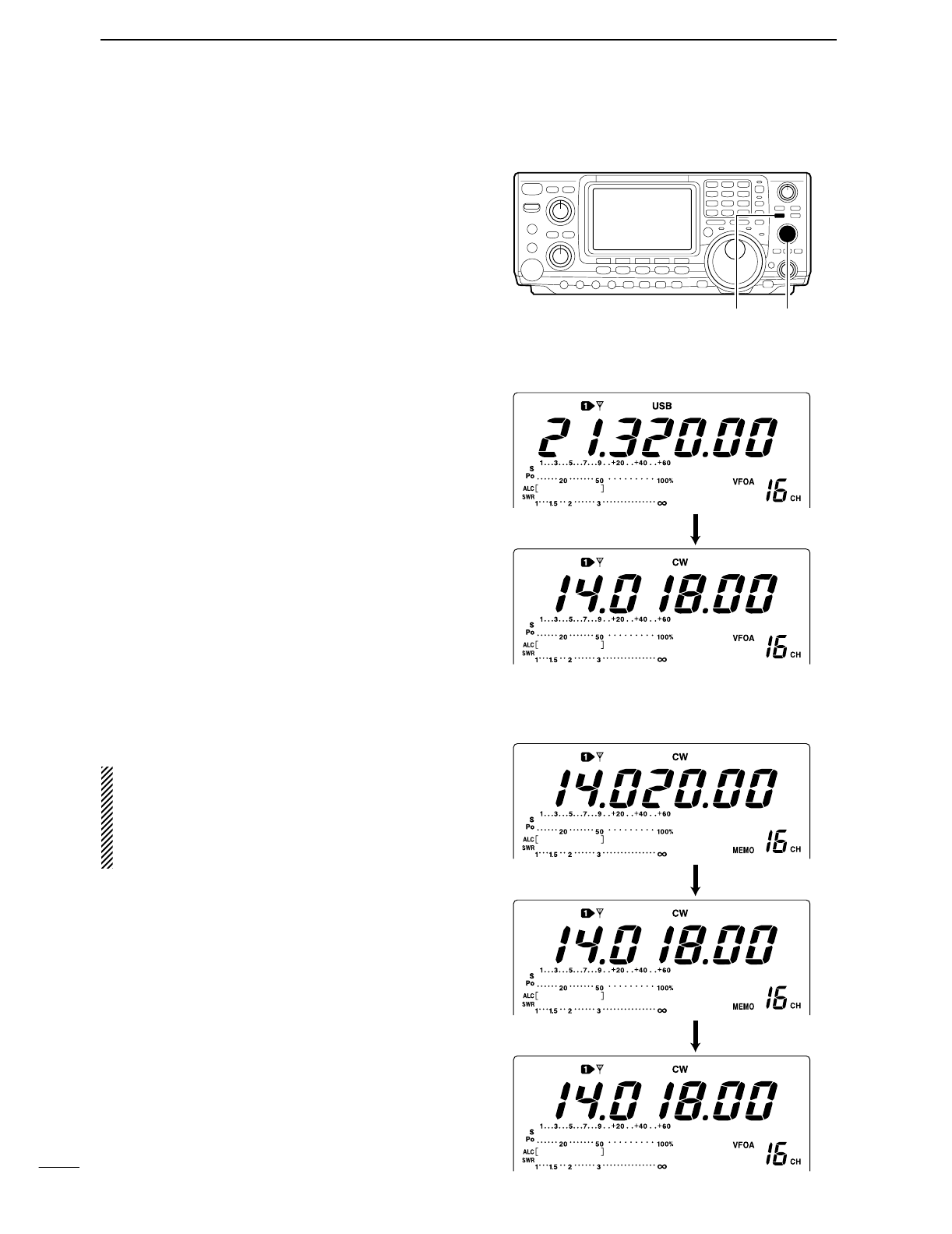
■Frequency transferring
The contents of a memory channel (frequency, oper-
ating mode, etc.) can be transferred to the VFO.
Frequency transferring can be performed in either VFO
mode or memory mode.
DTransferring in VFO mode
This is useful for transferring programmed contents to
VFO.
qSelect VFO mode with [V/M].
wSelect the memory channel to be transferred with
[M-CH].
•“BLANK” appears if the selected memory channel is a
blank channel. In this case transferring is impossible.
ePush [V/M] for 1 sec. to transfer the frequency and
operating mode.
•3 beeps are emitted.
DTransferring in memory mode
This is useful for transferring frequency and operating
mode while operating in memory mode.
When you have changed the frequency or operat-
ing mode in the selected memory channel:
•Displayed frequency and mode are transferred.
•Programmed frequency and mode in the memory
channel are not transferred, and they remain in the
memory channel.
qSelect the memory channel to be transferred with
[M-CH] in memory mode.
•And, set the frequency or operating mode if required.
wPush [V/M] for 1 sec. to transfer the frequency and
operating mode.
•3 beeps are emitted when the transferring is successful.
•Displayed frequency and operating mode are transferred
to the VFO.
eTo return to VFO mode, push [V/M] momentarily.
[V/M][M-CH]
TRANSFERRING EXAMPLE IN VFO MODE
Operating frequency : 21.320 MHz/USB (VFO)
Contents of M-ch 16 : 14.018 MHz/CW
Push [V/M] for 1 sec.
TRANSFERRING EXAMPLE IN MEMORY MODE
Operating frequency : 14.020 MHz/CW (M-ch 16)
Contents of M-ch 16 : 14.018 MHz/CW
Set the frquency
Push [V/M] for 1 sec.
then push [V/M]
66
7
MEMORY OPERATION
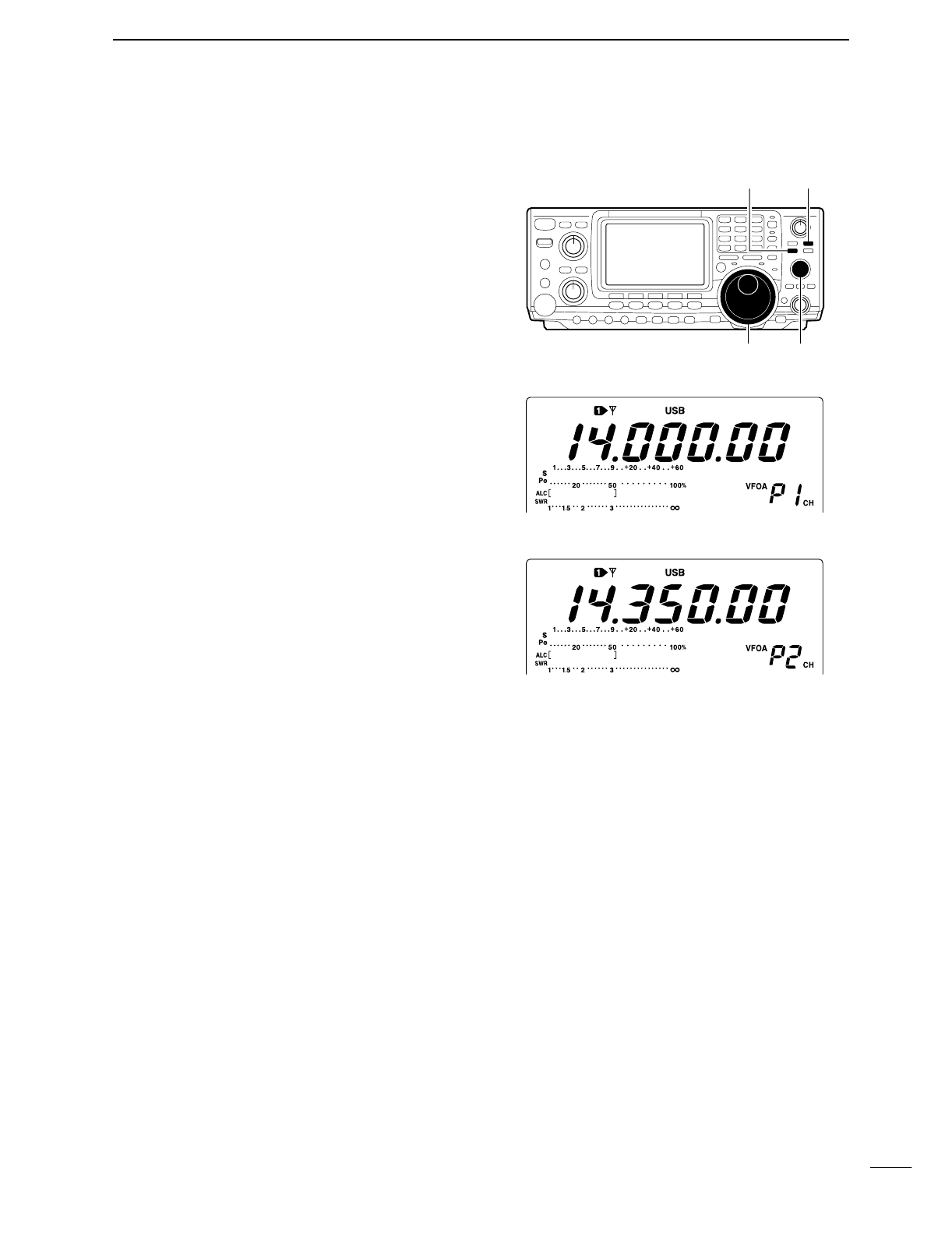
■Programming scan edges
Memory channels P1 and P2 are the program scan
edges. They are used to program an upper and lower
frequency for programmed scan (p. 71). By default, P1
is programmed with 0.50000 MHz and P2 is pro-
grammed with 29.99999 MHz. If P1 and P2 are pro-
grammed with the same frequencies, programmed
scan will not proceed.
[EXAMPLE]: Programming 14.00000 MHz into P1
and 14.35000 MHz into P2.
qPush [V/M] to select VFO mode, if necessary.
wRotate [M-CH] to select scan edge P1.
eRotate the tuning dial to set 14.00000 MHz as the
lower frequency.
rPush [MW] for 1 sec. to program 14.00000 MHz
into scan edge P1.
•3 beeps are emitted.
tRotate [M-CH] to select scan edge P2.
yRotate the tuning dial to set 14.35000 MHz as the
upper frequency.
uPush [MW] for 1 sec. to program 14.35000 MHz
into scan edge P2.
•3 beeps are emitted.
•When programmed scan is activated (p. 71) scanning
will search the frequencies between 14.00000 MHz and
14.35000 MHz for signals.
[V/M]
Tuning dial [M-CH]
[MW]
• After steps w to r
• After steps t to u
67
7MEMORY OPERATION
■Assigning memory names
All memory channels (including scan edges) can be
tagged with alphanumeric names of up to 9 characters
each.
[EXAMPLE]: Programming “DX spot” into memory
channel 99.
qPush [V/M] to select memory mode, if necessary.
wRotate [M-CH] to select memory channel 99.
ePush [MENU] several times to select M2.
rPush [F2 MEM] to select the memory name screen.
tPush [F1 EDT] to edit memory channel name.
•A cursor appears and blinks.
•Memory channel names of blank channels cannot be
edited.
yPush [F1] several times to select the type of char-
acters for input.
•“ABC” inputs capital letters A to Z.
•“abc” inputs small letters a to z.
•“etc” is used to input other characters— ! # $ % & ¥ ? ”
’` ^ + – ✱/ . , : ; = < > ( ) [ ] { } | _ –are available.
•Use the keypad to directly input numerals, “0” to “9,” in-
cluding a decimal point.
uRotate the tuning dial to select the first character for
input.
iPush [F2 ç] or [F3 å] to move the cursor forwards
or backwards, respectively.
•Push [F5 SPC] to input a space and [F4 DEL] to delete
the selected character.
oRepeat steps wto ito program another memory
channel’s name, if desired.
!0 Push [MENU] to set the memory channel name and
return to the memory name menu.
•Push [MENU] 1 more times to return to M2.
[V/M]
Tuning dial [M-CH][MENU]
F 1
F
2F
3
F
4
F
5
F 1
F
2F
3
F
4
F
5
F 1
F
2F
3
F
4
F
5
F 1
F
2F
3
F
4
F
5
F 1 F 2 F 3 F 4 F 5
SCN
MEM
SWR
TCN
VSC
EDT
(
)
SEL
14.195OO
USB
ABC
DEL
SPC
Push [F2 MEM]
Push [F2 MEM]
ABC
DEL
SPC
DX
• During assigning a memory names
abc
DEL
SPC
DX
spot
• After assigning a memory names
Input space
Delete a character
Move cursor forwards
Move cursor backwards
Selects character type
68
7
MEMORY OPERATION
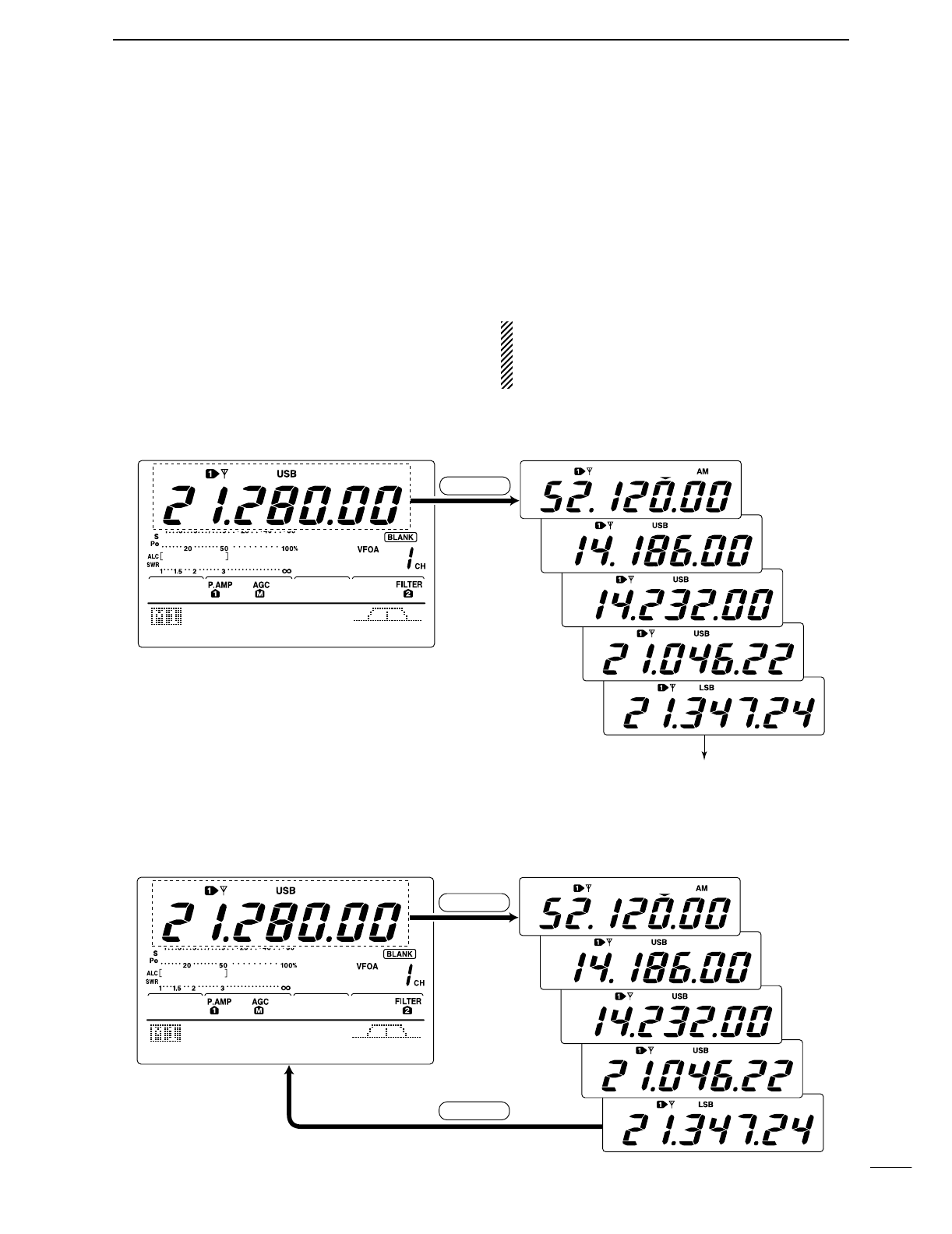
■Memo pads
The transceiver has a memo pad function to store fre-
quency and operating mode for easy write and recall.
The memo pads are separate from memory channels.
The default number of memo pads is 5, however, this
can be increased to 10 in set mode if desired. (p. 84)
DWriting frequencies and operating
modes into memo pads
➥Push [MP-W] to store the displayed frequency and
operating mode into a memo pad.
•Each push of [MP-W] stores a frequency and mode into
the next available memo pad; when you write a 6the (or
11the) frequency and operating mode, the oldest written
frequency and operating mode are automatically erased
to make room for the new settings.
D
Recalling a memo pad
➥Push [MP-R] to recall a memo pad.
•Each push of [MP-R] recalls a memo pad, starting from
the most recently written.
NOTE: Each memo pad must have its own unique
combination of frequency and operating mode;
memo pads having identical settings cannot be writ-
ten.
AGC
DUP
CMP
TBW
SCP
MP-W
Erased
In this example, pushing [MP-W] enters 21.28000 MHz
USB into the top memo pad and erases the oldest
memo pad (21.34724 MHz LSB).
• Displayed frequency and mode • Stored in next available memo pad
AGC
DUP
CMP
TBW
SCP
• VFO or memory mode • Memo pads
MP-R
MP-R
7
69
SCANS
■Scan types
■Preparation
•Channels
For programmed scan:
Program scan edge frequencies into scan edge mem-
ory channels P1 and P2.
For ∂F scan:
Set the ∂F span (∂F scan range) in the scan screen.
For memory scan:
Program 2 or more memory channels except scan
edge memory channels.
For select memory scan:
Designate 2 or more memory channels as select mem-
ory channels. To designate the channel as a select
memory channel, choose a memory channel, then
push [F3 SEL] in the scan screen, or push [F5 SEL]
in the memory name screen.
•Scan resume ON/OFF
You can select the scan to resume or cancel when de-
tecting a signal, in set mode. Scan resume ON/OFF
must be set before operating a scan. See p. 70 for
ON/OFF setting and scan resume condition details.
•Scan speed
Scan speed can be selected from 2 levels, high or low,
in set mode. See p. 70 for details.
•Squelch condition
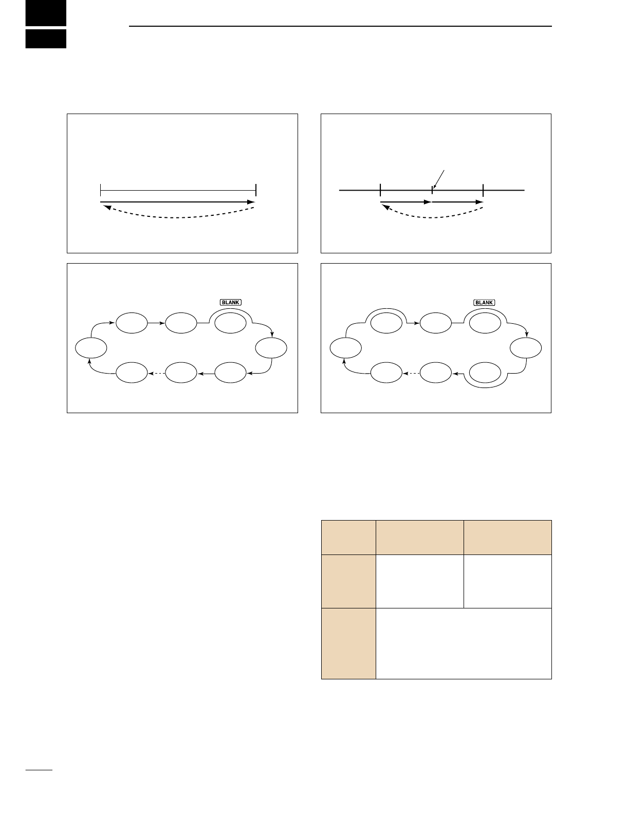
PROGRAMMED SCAN
Repeatedly scans between two scan edge frequencies
(scan edge memory channels P1 and P2).
This scan operates in VFO mode.
SELECT MEMORY SCAN
Repeatedly scans all select memory channels.
∂F SCAN
Repeatedly scans within ∂F span area.
This scan operates in memory mode.This scan operates in memory mode.
This scan operates in both VFO and memory modes.
Scan
Scan edge
P1 or P2 Scan edge
P2 or P1
Jump
Mch 1 Mch 5
Mch 2 Mch 3 Mch 4
Mch 6Mch 7Mch 99
MEMORY SCAN
Repeatedly scans all programmed memory channels.
Mch 1 Mch 5
Mch 2 Mch 3 Mch 4
Mch 6Mch 7Mch 99
SEL
SELSEL
SEL SEL
SEL
SELSEL
SEL SEL
ScanScan
–∂F frequency +∂F frequency
Start frequency
Jump
SQUELCH
CLOSED
SQUELCH
OPEN
Scan stops when detecting a signal.
If you set scan resume ON in scan set
mode, the scan pauses for 10 sec. when
detecting a signal, then resumes. When a
signal disappears while scan is paused,
scan resumes 2 sec. later.
The scan continues
until it is stopped
manually, and does
not pause even if it
detects signals.
Scan pauses on
each channel when
the scan resume is
ON; not applicable
when OFF.
SCAN PROGRAMMED
STARTS SCAN MEMORY SCAN
WITH
70
7
SCANS
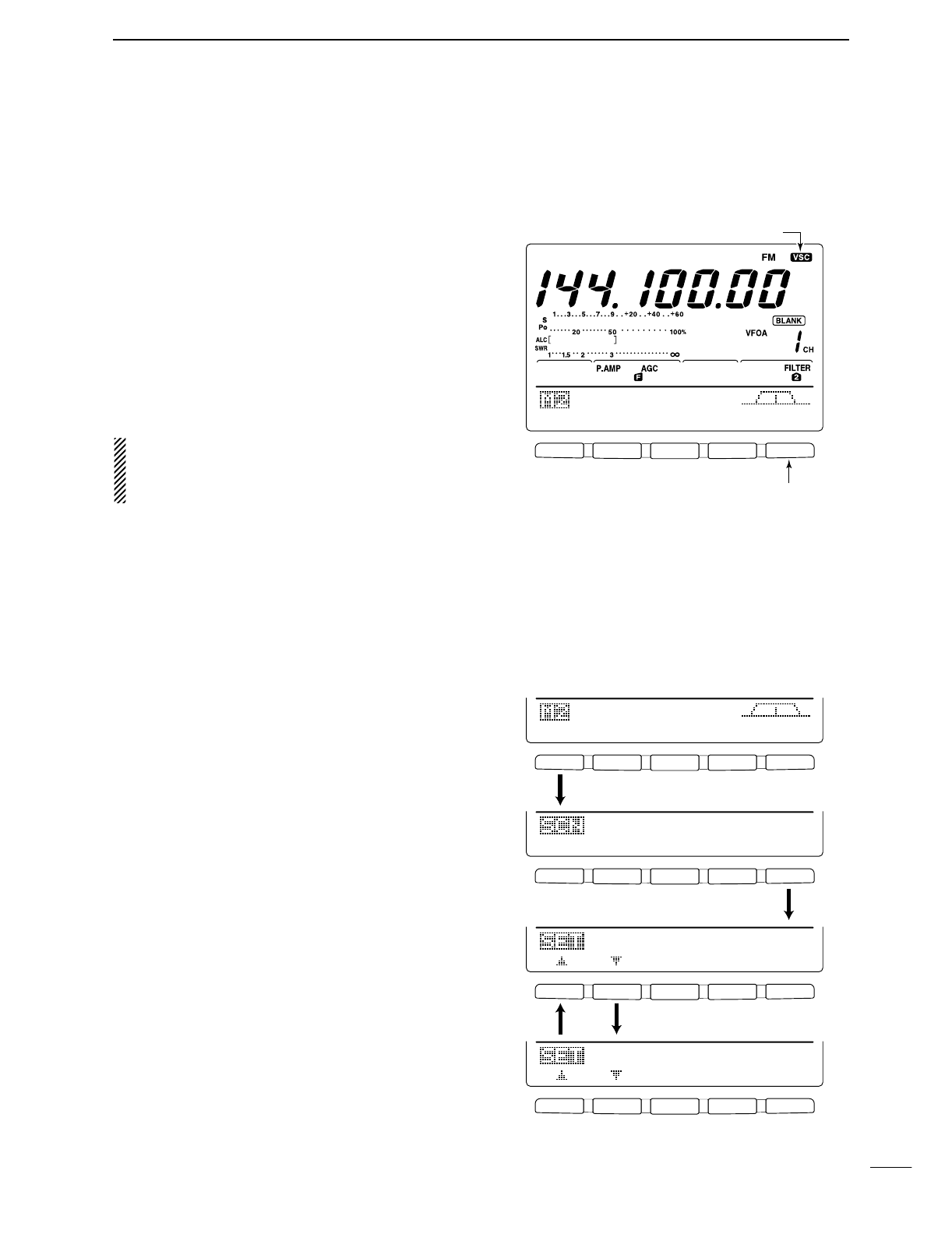
■Voice squelch control function
This function is useful when you don’t want unmodu-
lated signals pausing or cancelling a scan. When the
voice squelch control function is activated, the receiver
checks received signals for voice components.
If a receiver signal includes voice components, and the
tone of the voice components changes within 1 sec.,
scan pauses (or stops). If the received signal includes
no voice components or the tone of the voice compo-
nents does not change within 1 sec., scan resumes.
➥While M2 is selected with [MENU], push [F5 VSC]
to switch the VSC (Voice Squelch Control) function
ON and OFF.
•“VSC” appears when the function is activated.
•The VSC function activates for any scan.
•The VSC function resumes the scan on unmodu-
lated signals, regardless of the scan resume condi-
tion is set to ON or OFF.
■Scan set mode
When the squelch is open, scan continues until it is
stopped manually— it does not pause on detected sig-
nals. When squelch is closed, scan stops when de-
tecting a signal, then resumes according to the scan
resume condition. Scan speed and the scan resume
condition can be set using the scan set mode.
qPush[MENU] to select M2.
wPush [F1 SCN] to select scan menu.
ePush [F5 SET] to select scan set mode.
rPush [F1 ≤] or [F2 ≥] to select SCAN Speed
item.
tRotate the tuning dial to select scan speed from
high and low.
•“HIGH”: scan is faster
•“LOW”: scan is slower
yPush [F2 ≥] to select SCAN Resume item.
uRotate the tuning dial to select scan resume func-
tion from ON and OFF.
•“ON”: when detecting a signal, scan pauses for
10 sec., then resumes. When a signal disap-
pears, scan resumes 2 sec. later.
•“OFF”: when detecting a signal, cancels scanning.
iPush [MENU] to return to scan menu.
F 1
F
2F
3
F
4
F
5
F 1 F 2 F 3 F 4 F 5
F 1
F
2F
3
F
4
F
5
F 1
F
2F
3
F
4
F
5
SCN
MEM
SWR
TCN
VSC
PRO
∂
F
FIN
SPN
SET
∂
F:±1Ok
Push [F1]
Push [F5]
SCAN
Speed
HIGH
1
Push [F1] or [F2]
SCAN
Resume
ON
2
F 1 F 2 F 3 F 4 F 5
SCN
MEM
SWR
TCN
VSC
Push [F5] to turn the VSC function ON and OFF.
VSC indicator
71
8SCANS
■Programmed scan/Fine programmed scan (VFO mode)
Programmed scan searches for signals between scan
edge memory channels P1 and P2. The default fre-
quencies for these memories are 0.500000 MHz and
29.99999 MHz, respectively. See p. 66 for scan edges
programming.
qPush [V/M] to select VFO mode, if necessary.
wSelect the desired operating mode.
•The operating mode can also be changed while scan-
ning.
ePush [TS] to select a tuning step.
•The tuning step can also be changed while scanning.
rPush [MENU] to select M2.
tPush [F1 SCN] to select the scan menu.
•See p. 69 for scan condition.
•If the [RF/SQL] control function is set as “AUTO,” the
squelch is always open in SSB, CW and RTTY modes.
yPush [F1 PRO] to start the programmed scan.
•The MHz and kHz decimal points blink while scanning.
uWhen the scan detects a signal, the scan stops,
pauses or ignores it depending on the resume, VSC
setting and the squelch condition.
iTo cancel the scan, push [F1 PRO].
•Rotating the tuning dial during scan also cancels scan
operation.
If the same frequencies are programmed into the
scan edge memory channel P1 and P2, pro-
grammed scan does not start.
DAbout the Fine programmed scan
During programmed scan, when a signal is received,
scan continues, but the tuning step is temporarily set to
10 Hz.
qFollow steps qto yabove to start programmed
scan.
wDuring programmed scan, push [F3 FIN] to switch
between programmed scan and fine programmed
scan operation.
ePush [F1 PRO] to cancel the scan.
•Rotating the tuning dial during scan also cancels scan
operation.
[TS]
Tuning dial
[MENU]
[V/M]
Mode keys
F 1
F
2F
3
F
4
F
5
F 1 F 2 F 3 F 4 F 5
F 1
F
2F
3
F
4
F
5
SCN
MEM
SWR
TCN
VSC
PRO
∂
F
FIN
SPN
SET
∂
F:±1Ok
PRO
∂
F
FIN
SPN
SET
PROG
SCAN
Push [F1]
Push [F1] to start/cancel the scanning.
Push [F1]
F 1
F
2F
3
F
4
F
5
F 1
F
2F
3
F
4
F
5
PRO
∂
F
FIN
SPN
SET
PROG
SCAN
PRO
∂
F
FIN
SPN
SET
F-PROG
SCAN
Push [F3] to switch
between programmed
scan and fine pro-
grammed scan.
72
8
SCANS
■Memory scan operation (Memory mode)
Memory scan searches through memory channel 1 to
99 for signals. Blank (un-programmed) memory chan-
nels are skipped.
qPush [V/M] to select memory mode, if necessary.
wPush [MENU] to select M2.
ePush [F1 SCN] to select the scan menu.
•See p. 69 for scan condition.
•If the [RF/SQL] control function is set as “AUTO,” the
squelch is always open in SSB, CW and RTTY modes.
rPush [F1 MEM] to start the memory scan.
•The MHz and kHz decimal points blink while scanning.
•At least 2 memory channels must be programmed for
memory scan to proceed.
tTo cancel the scan, push [F1 MEM].
•Rotating the tuning dial during scan also cancels scan
operation.
■Select memory scan
Select memory scan searches through memory chan-
nel set as “select” for signals. See below for setting
and deleting select memory channels.
qFollow the steps qto rabove to start memory
scan.
wDuring memory scan, push [F3 SEL] to switch be-
tween memory scan and select memory scan.
•At least 2 memory channels must be set as the select
channel.
ePush [F1 MEM] to cancel the scan.
•Rotating the tuning dial during scan also cancels scan
operation.
DSetting/Cancelling select memory channels
All memory channels, except scan edges (P1 and P2),
can be set as a select memory channels.
➥While the scan menu is selected, push [F3 SEL] to
set/cancel the displayed memory channel as a se-
lect channel; or while memory name screen is indi-
cated, push [F5 SEL] to set/cancel the displayed
memory channel as a select memory channel.
•“SEL” appears when the channel set as a select memory
channel.
•“SEL” disappears when cancelled.
•Push [F3 SEL]/[F5 SEL] for 1 sec to cancels all select
memory settings.
Tuning dial[MENU] [V/M]
F 1
F
2F
3
F
4
F
5
MEM
∂
F
SEL
SPN
SET
MEMO
SCAN
Push [F1] to start/cancel the scanning.
F 1
F
2F
3
F
4
F
5
F 1
F
2F
3
F
4
F
5
MEM
∂
F
SEL
SPN
SET
MEMO
SCAN
MEM
∂
F
SEL
SPN
SET
SEL-MEMO
SCAN
Push [F3] to switch
between memory scan
and select memory
scan.
F 1
F
2F
3
F
4
F
5
F 1
F
2F
3
F
4
F
5
∂
F:±1Ok
MEM
∂
F
SEL
SPN
SET
Push [F3] to set/cancel as a select channel.
Select memory inidcator
Push [F3] to set/cancel as a select channel.
EDT
(
)
SEL
14.195OO
USB
• Scan menu
• Memory name screen
73
8SCANS
■∂F scan operation and Fine ∂F scan
∂F scan searches for signals within the specified
range with the displayed VFO or memory channel fre-
quency as for center frequency. The frequency range
is specified by the span.
qPush [V/M] to select VFO mode or memory mode,
as desired.
wSet center frequency of the ∂F scan.
ePush [MENU] to select M2.
rPush [F1 SCN] to select the scan menu.
•See p. 69 for scan condition.
•If the [RF/SQL] control function is set as “AUTO,” the
squelch is always open in SSB, CW and RTTY modes.
tSet the ∂F span by pushing [F4 SPN].
•±5 kHz, ±10 kHz, ±20 kHz, ±50 kHz, ±100 kHz,
±500 kHz and ±1 MHz are selectable.
yPush [F2 ∂F] to start the ∂F scan.
•Decimal points blink while scanning.
uWhen the scan detects a signal, the scan stops,
pauses or ignores it depending on the VSC, resume
setting and the squelch condition.
yPush [F2 ∂F] to cancel the ∂F scan.
•Rotating the tuning dial during scan also cancels scan
operation.
DAbout the Fine ∂F scan
During ∂F scan, when a signal is received, scan con-
tinues, but the tuning step is temporarily set to 10 Hz.
qFollow steps qto yabove to start programmed
scan.
wDuring ∂F scan, push [F3 FIN] to switch between
∂F scan and fine ∂F scan operation.
ePush [F2 ∂F] to cancel the scan.
•Rotating the tuning dial during scan also cancels scan
operation.
Keypad
Tuning dial
[MENU]
[V/M]
F 1
F
2F
3
F
4
F
5
F 1 F 2 F 3 F 4 F 5
F 1
F
2F
3
F
4
F
5
SCN
MEM
SWR
TCN
VSC
PRO
∂
F
FIN
SPN
SET
∂
F:±1Ok
PRO
∂
F
FIN
SPN
SET
∂
F
SCAN
Push [F1]
Push [F2] to start/cancel the scanning.
Push [F2] Push [F4] to select the span.
F 1
F
2F
3
F
4
F
5
F 1
F
2F
3
F
4
F
5
PRO
∂
F
FIN
SPN
SET
∂
F
SCAN
PRO
∂
F
FIN
SPN
SET
F-
∂
F
SCAN
Push [F3] to switch
between programmed
scan and fine pro-
grammed scan.
74
8
SCANS
■Tone scan/DTCS code scan operation
By monitoring a signal that is being operated with a re-
peater, tone squelch or DTCS, you can determine the
tone frequency necessary to open a repeater or the
squelch.
qPush [AM/FM] to select FM mode.
wPush [MENU] several times to select M1.
ePush [F4 TONE] for 1 sec. to enter tone set mode.
rPush [F1 TON] to select the tone type to be
scanned.
•“Rptr Tone” for repeater tone, “TSQL Tone” for
tone squelch and “DTCS Code” for DTCS code can be
selected.
•When selecting DTCS code to be scanned, push [F5]
several times to select the DTCS code polarity.
“NN”: Normal polarity for both transmit and receive.
“NR”: Normal polarity for transmit and reverse polarity
for receive.
“RN”: Reverse polarity for transmit and normal polarity
for receive.
“RR”: Reverse polarity for both transmit and receive.
tPush [F2 SCN] to start the tone scan function.
•“Rptr Tone SCAN,” “TSQL Tone SCAN” or
“DTCS Code SCAN” blinks when repeater tone scan,
tone squelch scan or DTCS code scan is operated, re-
spectively.
yWhen matched tone or code is found, the scan
pauses and the tone frequency or code is set for the
selected tone as in step r.
When the tone scan or DTCS code scan is operated
in memory or call channel, the detected tone frequency
or code can be used for temporarily.
To keep the detected tone frequency or code setting
for memory contents, you must over-written the mem-
ory or call channel.
uPush [F2 SCN] to cancel the tone scan function.
•Rotating the tuning dial during scan also cancels scan
operation.
F 1 F 2 F 3 F 4 F 5
F 1 F 2 F 3 F 4 F 5
F 1 F 2 F 3 F 4 F 5
F 1 F 2 F 3 F 4 F 5
F 1 F 2 F 3 F 4 F 5
AGC
DUP
CMP
TON
SCP
TON
SCN
88.5Hz
Rptr
Tone
TON
SCN
88.5Hz
Rptr
Tone
SCAN
Push [F4] for 1 sec.
Push [F1] several times to select tone type.
• Rpeater tone scan
• Tone squelch tone scan
• DTCS code scan
TON
SCN
88.5Hz
TSQL
Tone
SCAN
TON
SCN
O23-NN
DTCS
Code
SCAN
Push [F2] to start/cancel the scan.
Push [F2] to start/cancel the scan.
Push [F2] to start/cancel the scan.
Push [F1] several times to select porality.
9
75
ANTENNA TUNER OPERATION
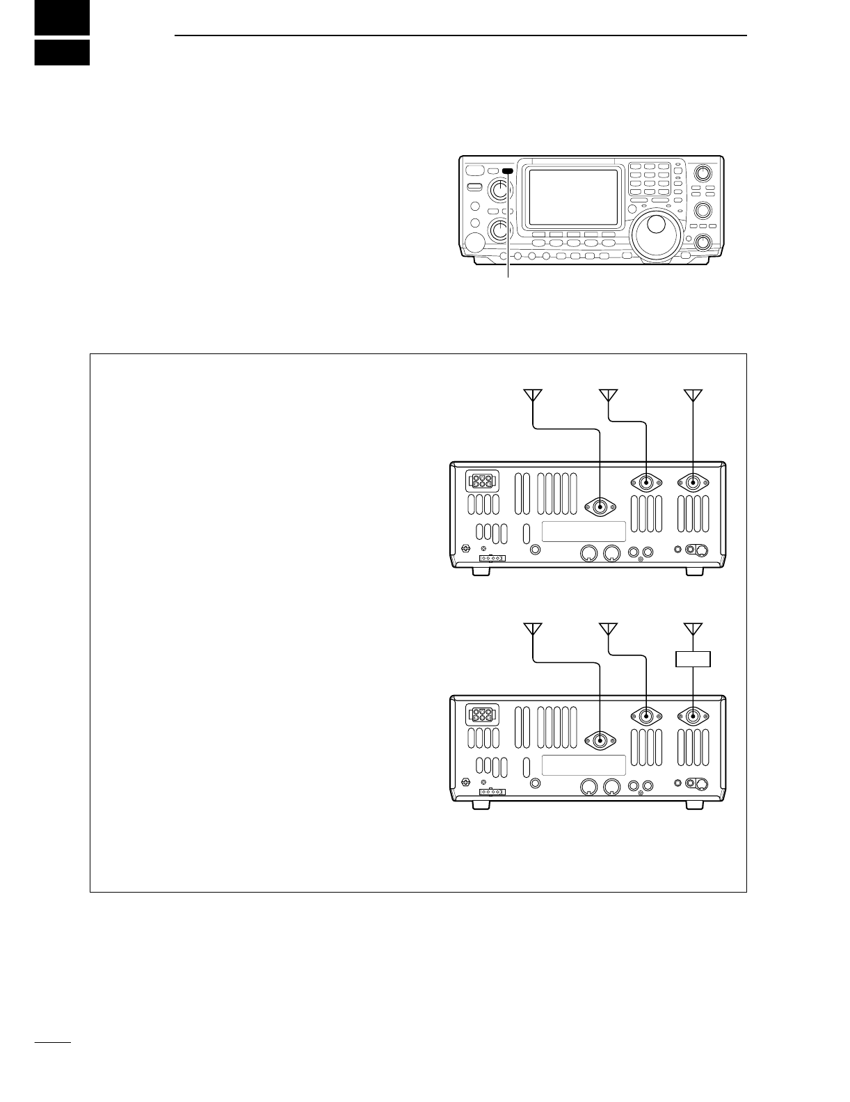
■Antenna connection and selection
The IC-746PRO has 2 antenna connectors for the
HF/50 MHz bands, [ANT1] and [ANT2], and 1 antenna
connector for the 144 MHz band; a total of 3 antenna
connectors.
For each operating band the IC-746PRO covers, there
is a band memory which can memorize a selected an-
tenna. When you change the operating frequency be-
yond a band, the previously used antenna is automat-
ically selected (see below) for the new band. This
function is convenient when you use 2 antennas for HF
and 50 MHz bands operation.
•Antenna select function: “Auto”
Once an antenna has been selected for use with a
band by pushing [ANT], the antenna is automatically
selected whenever that band is accessed.
[EXAMPLE]: a 3.5/7 MHz antenna is connected to
[ANT1], a 21/28/50 MHz antenna is connected to
[ANT2]. When the antenna selector function is set to
“Auto,” an antenna is automatically selected when
changing bands.
•Antenna select function: “Manual”
When “Manual” is selected, you can use the [ANT1]
and [ANT2], however, band memory does not func-
tion. In this case you must select an antenna manu-
ally. However, the 144 MHz antenna will still be
selected automatically.
[EXAMPLE]: an optional antenna tuner and HF an-
tenna are connected to [ANT1] and a 50 MHz an-
tenna is connected to [ANT2].
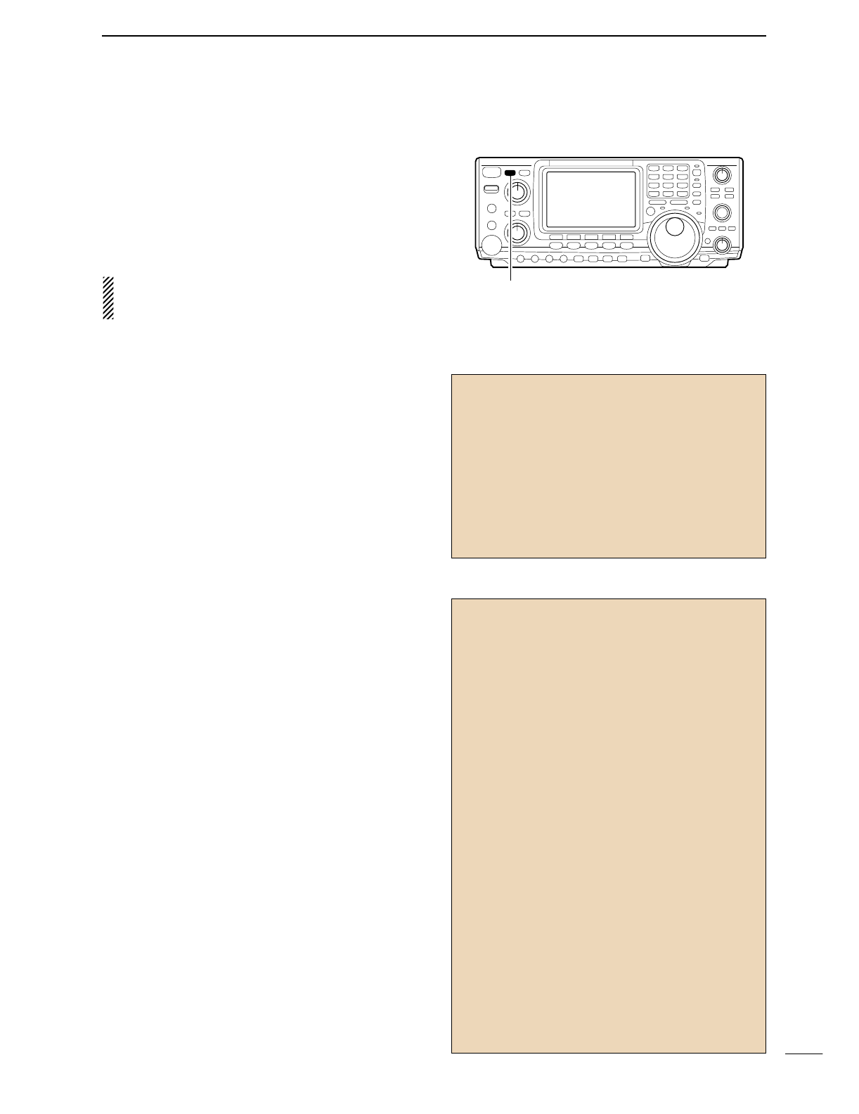
•Antenna select function: “OFF”
In this case, only [ANT1] and the 144 MHz antenna
connector can be used. [ANT] switch does not func-
tion.
[ANT]
144 MHz 21/28/50 MHz 3.5/7 MHz
[ANT1][ANT2]
144 MHz band 50 MHz band HF bands
[ANT1][ANT2]
AH-4
76
9
ANTENNA TUNER OPERATION
■Antenna tuner operation
The internal automatic antenna tuner matches the
transceiver to the connected antenna automatically.
Once the tuner matches an antenna, the variable ca-
pacitor angles are memorized as a preset point for each
frequency range (100 kHz steps). Therefore, when you
change the frequency range, the variable capacitors are
automatically preset to the memorized point.
CAUTION: NEVER transmit with the tuner ON
when no antenna is connected. This will damage
the transceiver. Be careful of the antenna selection.
DTUNER OPERATION
➥Push [TUNER] to turn the internal antenna tuner
ON. The antenna is tuned automatically when the
antenna SWR is higher than 1.5:1.
•When the tuner is ON, the “TUNE” indicator appears.
•MANUAL TUNING
During SSB operation at low voice levels, the internal
tuner may not be tuned correctly. In such cases, man-
ual tuning is helpful.
➥Push [TUNER] for 1 sec., to start manual tuning.
•A side tone is emitted and [TUNER] blinks while tuning.
•If the tuner cannot reduce the SWR to less than 1.5:1
after 20 sec. of tuning, the [TUNER] switch indicator
goes out.
•AUTOMATIC TUNER START (HF bands only)
If you want to deactivate the tuner under conditions
of VSWR 1.5:1 or less, use the auto tuner start func-
tion and turn the tuner OFF. This function activates
the tuner automatically when the SWR exceeds 1.5:1.
This function is turned ON in set mode. (p. 83).
•PTT TUNER START
The tuner is always tuned when the PTT is pushed
after the frequency is changed (more than 1% from
last-tuned frequency). This function removes the
“push and hold [TUNER]” operation and activates for
the first transmission on a new frequency.
This function is turned ON in set mode. (p. 83).
•Antenna tuner of the IC-PW1
When using an external antenna tuner such as the
IC-PW1’s tuner, tune with the external antenna tuner,
while the internal tuner is turned OFF. After tuning is
completed, turn the internal tuner ON. Otherwise,
both tuners tune simultaneously and correct tuning
may not be obtained.
See the instruction manual included with each an-
tenna tuner for their respective operations.
[TUNER]
DIf the tuner cannot tune the antenna
Check the following and try again:
•the [ANT] connector selection.
•the antenna connection and feedline.
•the unaltered antenna SWR. (Less than 3:1 for HF bands;
Less than 2.5:1 for 50 MHz band)
•the transmit power. (8 W for HF bands; 15 W for 50 MHz
band)
•the power source voltage/capacity.
If the tuner cannot reduce the SWR to less than 1.5:1
after checking the above, perform the following:
•repeat manual tuning several times.
•tune with a 50 Ωdummy load and re-tune the antenna.
•turn power OFF and ON.
•adjust the antenna cable length.
(This is effective for higher frequencies in some cases.)
•Some antennas, especially for low bands, have a nar-
row bandwidth. These antennas may not be tuned at the
edge of their bandwidth, therefore, tune such an an-
tenna as follows:
[Example]: Suppose you have an antenna which has an
SWR of 1.5:1 at 3.55 MHz and an SWR of 3:1 at 3.8 MHz.
qPush [TUNER] to turn the antenna tuner ON.
wSelect CW mode.
eTurn OFF the break-in function. (p. 56)
rPush [TRANSMIT] to set to the transmit condition.
tSet 3.55 MHz and key down.
ySet 3.80 MHz and key down.
uPush [TRANSMIT] to return to the receive condition.
NOTES:
•The internal antenna tuner can only tune the HF and
50 MHz bands— the 144 MHz band cannot be tuned.
•DO NOT transmit if no antenna is connected to [ANT1]
and [ANT2].
•When 2 antennas are connected, select the antenna to
be used with [ANT].
•If the SWR is higher than about 1.5:1 when tuning above
100 kHz on an antenna’s preset point, push [TUNER] for
1 sec. to start manual tuning.
•The internal tuner may not be able to tune in AM mode. In
such cases, push [TUNER] for 1 sec. to manually tune.
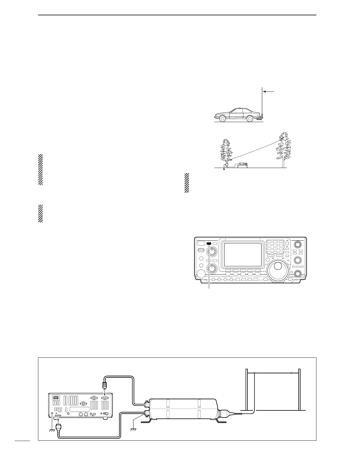
■Optional external tuner operation
DAH-4 HF/50 MHz AUTOMATIC ANTENNA TUNER
The AH-4 matches the IC-746PRO to a long wire an-
tenna more than 7 m/23 ft long (3.5 MHz and above).
•See the AH-4 instruction manual for AH-4 installation and
antenna connection details.
NEVER operate the AH-4 without an antenna wire.
The tuner and transceiver will be damaged.
NEVER operate the AH-4 when it is not grounded.
Transmitting before tuning may damage the trans-
ceiver. Note that the AH-4 cannot tune when using a
1⁄2λlong wire or multiple of the operating frequency.
When connecting the AH-4, the antenna connector
assignments are [ANT2] for the internal tuner and
[ANT1] for the AH-4. The antenna indicator in the
LCD displays “EXT” when the AH-4 is connected
and selected.
DAH-4 operation
Tuning is required for each frequency. Be sure to
re-tune the antenna before transmitting when you
change the frequency— even slightly.
qSet the desired frequency in an HF or 50 MHz
band.
•The AH-4 may not operate on frequencies outside of
ham bands.
wPush [TUNER] for 1 sec.
•“TUNER” blinks while tuning.
e“TUNE” appears constantly when tuning is com-
plete.
•When the connected wire cannot be tuned, the “TUNE”
indicator goes out, and the AH-4 is bypassed. At that
point the antenna wire connection root is to the trans-
ceiver directly, and not via AH-4 antenna tuner.
r
To bypass the AH-4 manually, push [TUNER].
AH-4 setting example:
RWARNING: HIGH VOLTAGE!
NEVER touch the antenna element while tuning or
transmitting.
77
9ANTENNA TUNER OPERATION
For mobile operation
For outdoor operation
Long wire
Optional AH-2b
antenna element
[TUNER]
Coaxial cable (from AH-4)
ANT1
Transceiver
Ground AH-4
Control cable
Long wire or optional AH-2b
•Connecting the AH-4
10
78
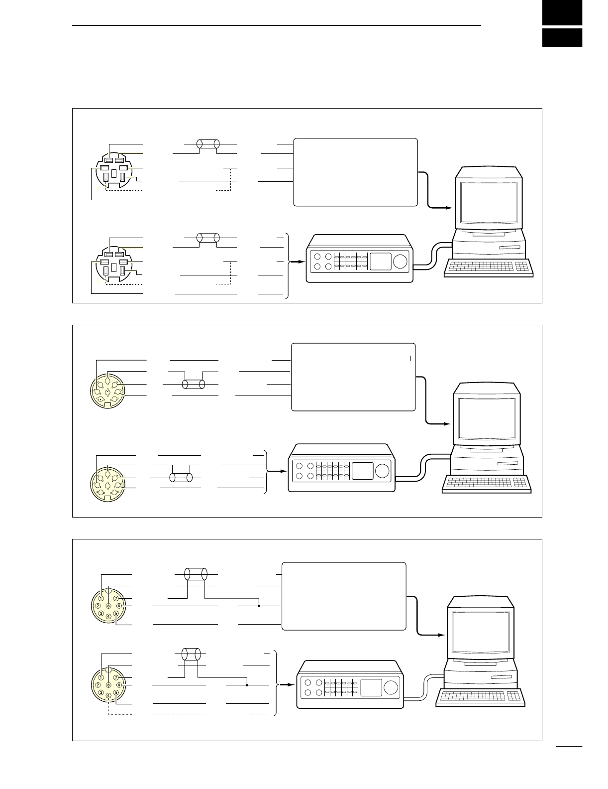
DATA COMMUNICATION
■Connections
■ When connecting to [DATA]
• When using a PC application
• When using a TNC
q DATA IN
w GND
r DATA OUT (9600 bps)
y P SQL*
t AF OUT (1200 bps)
e PTT P
TX AUDIO
GND
RX AUDIO
SQL
PTT
q DATA IN
w GND
r DATA OUT (9600 bps)
y P SQL*
t AF OUT (1200 bps)
e PTT P
TX AUDIO
GND
TNC
PC
RS-232C
RX AUDIO
SQL
PTT
Connect to serial port, parallel
port, speaker jack, microphone
jack and line IN/OUT jack, etc.
See the instruction manual of the
application for details.
*When connecting the squelch line, cpnsult the necessary manual (TNC, etc.)
PC
RS-232C
TNC or scan converter
Connect to serial port, parallel
port, speaker jack, microphone
jack and line IN/OUT jack, etc.
See the instruction manual of the
application for details.
■ When connecting to [ACC(1)]
• When using a PC application
• When using a TNC
1
2
3
45
67
8
Rear panel view
RTTY
GND
AF
SEND
RTTY
GND
AF
SEND
RTTY OUTPUT
GND
AUDIO INPUT
PTT
RTTY OUTPUT
GND
AUDIO INPUT
PTT
1
2
3
45
67
8
Connect to serial port, parallel
port, speaker jack, microphone
jack and line IN/OUT jack, etc.
See the instruction manual of the
application for details.
■ When connecting to [MIC]
• When using a PC application
• When using a TNC
PC
RS-232C
TNC or scan converter
MIC INPUT
AF OUTPUT
MIC GND
GND
PTT*
PTT*
MIC INPUT
AF OUTPUT
MIC GND
GND
PTT*
AUDIO OUTPUT
AF INPUT
GND
SQL†
AFSK OUTPUT
AF INPUT
GND
PTT*
SQL INPUT†*When using the VOX function, not need to connect. Refer to the external
equipment (TNC, etc.).
†When connecting the squelch line, consult the necessary manual (TNC, etc.).
79
10 DATA COMMUNICATION
■Packet (AFSK) operation
Before operating packet (AFSK) be sure to consult the
operating manual that came with your TNC.
qConnect a TNC and PC. (p. 77)
wPush a band key to select an operating band.
ePush [SSB] or [AM/FM] to select the desired operat-
ing mode.
•After LSB or USB is selected, push [SSB] for 1 sec. to
select LSB data or USB data mode, or after AM or FM is
selected, push [AM/FM] for 1 sec. to select AM data or
FM data mode.
•Generally, LSB is used on HF bands and FM is used for
packet operation on the VHF band.
rRotate the tuning dial to tune the desired signal.
tTransmit your AFSK signals using your computer’s
keyboard.
•Rotate [RF PWR] to set the output power.
•Relative strength of the transmitted signal is indicated in
the Po meter while operating the TNC.
•When operating in SSB (data) mode, adjust output
power so that the ALC reading in the ALC meter stays
in the ALC zone.
NOTE: When connecting a TNC to the ACC socket
on the rear panel, select SSB (LSB/USB) data mode
or disconnect the microphone and rotate [MIC
GAIN] fully counterclockwise.
When SSB data mode is selected, the audio input
from the [MIC] connector is automatically cut, and
use the audio input from the [ACC(1)].
And, when the SSB data mode is selected, signals
are transmitted with the fixed conditions as follow;
•Speech compressor : OFF
•Transmit bandwidth : MID
•Tx tone (Bass) : 0
•Tx tone (Trebles) : 0
DFrequency indication during AFSK operation
When operating AFSK in SSB mode, the indicated fre-
quency is the signals carrier point.
Band keys[TX] indicator[TRANSMIT]
[MIC GAIN] [AM/FM] Tuning dial
Selected mode indicator appear
[SSB]
• Example— LSB/LSB data mode
Mark freq.: 2125 Hz
Shift freq.: 200 Hz
2325 Hz
200 Hz 2125 Hz
Carrier point
(Displayed frequency)
80
10
DATA COMMUNICATION
■Adjusting the TNC output level
When setting data transmission speed to 9600 bps,
the data signal coming from the TNC is applied exclu-
sively to the internal limiter circuitry to automatically
maintain band width.
NEVER apply data levels from the TNC of over 0.6 V
p-p, otherwise the transceiver will not be able to main-
tain the band width and may possibly interfere with
other station.
DUsing with a level meter or synchroscope
When using a level meter or synchroscope, adjust the
TX audio output level (DATA IN level) from the TNC as
follows.
0.4 V p-p (0.2 Vrms) : recommended level
0.2–0.5 V p-p (0.1–0.25 Vrms) : acceptable level
DNot using a measuring device
qConnect transceiver to a TNC. (p. 00)
wEnter a test mode (“CAL,” etc.) on the TNC, then
transmit some test data.
e
When the transceiver fails to transmit the test data
or transmits sporadically (TX indicator doesn’t lights
or flashes):
-Decrease the TNC output level until the transmit
indicator lights continuously.
When transmission is not successful even though
the TX indicator lights continuously:
-Increase the TNC output level.
■Data transmission speed
For data communication, the transceiver can be set to
one of two data speeds: 9600 bps or less speed.
qPush [MENU] for 1 sec. to enter set mode.
wPush [F1 ≤] or [F2 ≥] to select the 9600bps
Mode item.
eRotate the tuning dial to turn ON and OFF the
9600 bps mode.
ON : 9600 bps of data speed
OFF : less than 9600 bps of data speed (default)
rPush [MENU] to return to previous indication.
21
ON
96OObps
Mode
21
OFF
96OObps
Mode
Select with the tuning dial
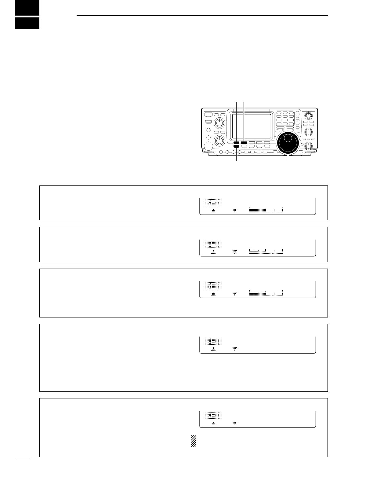
11
81
SET MODE
2. LCD Backlight
This item adjusts the brightness of the LCD from 0%
to 100% in 1% steps.
(default: 50%)
LCD
Backlight
5O%
2
■General set mode
DEntering set mode
Set mode is used for programming infrequently
changed values or conditions of functions.
•Set mode operation
qPush [MENU] several times to function menu indi-
cation, if necessary.
wPush [MENU] for 1 sec. to enter the set mode.
ePush [F1 ≤] or [F2 ≥] to select the desired item.
rSet the desired condition using the tuning dial.
•Push [F3] for 1 sec. to select a default condition or value.
uPush [MENU] to exit the set mode.
DSet mode items
1. LCD Contrast
This item adjusts the contrast of the LCD from 0% to
100% in 1% steps.
(default: 50%)
LCD
Contrast
5O%
1
3. Beep Level
This item adjusts the volume level for confirmation
beep tones from 0% to 100% in 1% steps. When
beep tones, the item 6. Beep (p. 81), are turned
OFF, this setting has no effect.
(default: 50%)
Beep
Level
3
5O%
4. Beep Level-lmt
This item allows you to set a maximum volume level
for confirmation beep tones. Confirmation beep tones
are linked to the [AF] control until a specified volume
level is reached—further rotation of the [AF] control
will not increase the volume of the beep tones.
ON Confirmation beep ON (default)
OFF Confirmation beep OFF
Beep
Level-lmt
4
ON
[F1 ≤]
Tuning dial[MENU]
[F2 ≥]
5. CAL. Marker
This item is used for a simple frequency check of the
transceiver.
ON Calibration marker ON
OFF Calibration marker OFF (default)
See p. 93 for calibration procedure.
Turn the calibration marker OFF after checking the
frequency of the transceiver.
Cal.
Marker
5
OFF
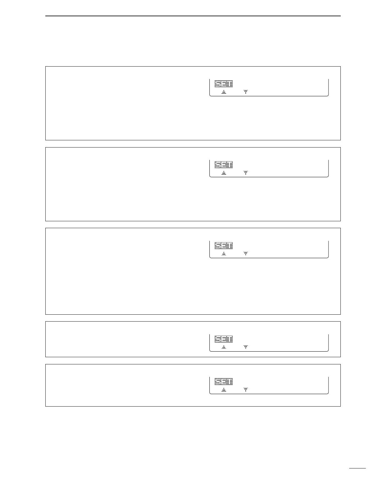
82
11
SET MODE
6. Beep
A beep sounds each time a switch is pushed to con-
firm it. This function can be turned OFF for silent op-
eration.
ON Confirmation beep ON (default)
OFF Confirmation beep OFF
The volume level can be set in 3. Beep Level.
(p. 80)
Beep
6
ON
7. Band Edge Beep
A beep sounds when an operating frequency enters
or exits an amateur band. This functions independent
of the confirmation beep setting (above).
ON Band edge beep ON (default)
OFF Band edge beep OFF
The volume level can be set in 3. Beep Level.
(p. 80)
Band
Edge
Beep
7
ON
8. RF/SQL Control
The [RF/SQL] control can be set as the RF/squelch
control (default), the squelch control only (RF gain is
fixed at maximum) or ‘Auto’(RF gain control in SSB,
CW and RTTY; squelch control in AM and FM).
RF+SQL [RF/SQL] control as RF/squelch con-
trol (default)
SQL [RF/SQL] control as squelch control
AUTO [RF/SQL] control as RF gain control
in SSB, CW and RTTY; squelch con-
trol in AM and FM
RF/SQL
Control
8
RF+SQL
9. Meter Peak Hold
This item turns the meter peak hold function ON and
OFF. When set to ON (default), peak meter reading
are displayed for about 0.5 sec.
Meter
Peak
Hold
9
ON
10. COMP Meter
This item turns the COMP meter indication ON and
OFF during transmit. When set to ON, the COMP
meter is displayed instead of the SWR meter.
(default: OFF)
1
O OFF
COMP
Meter
■General set mode (continued)
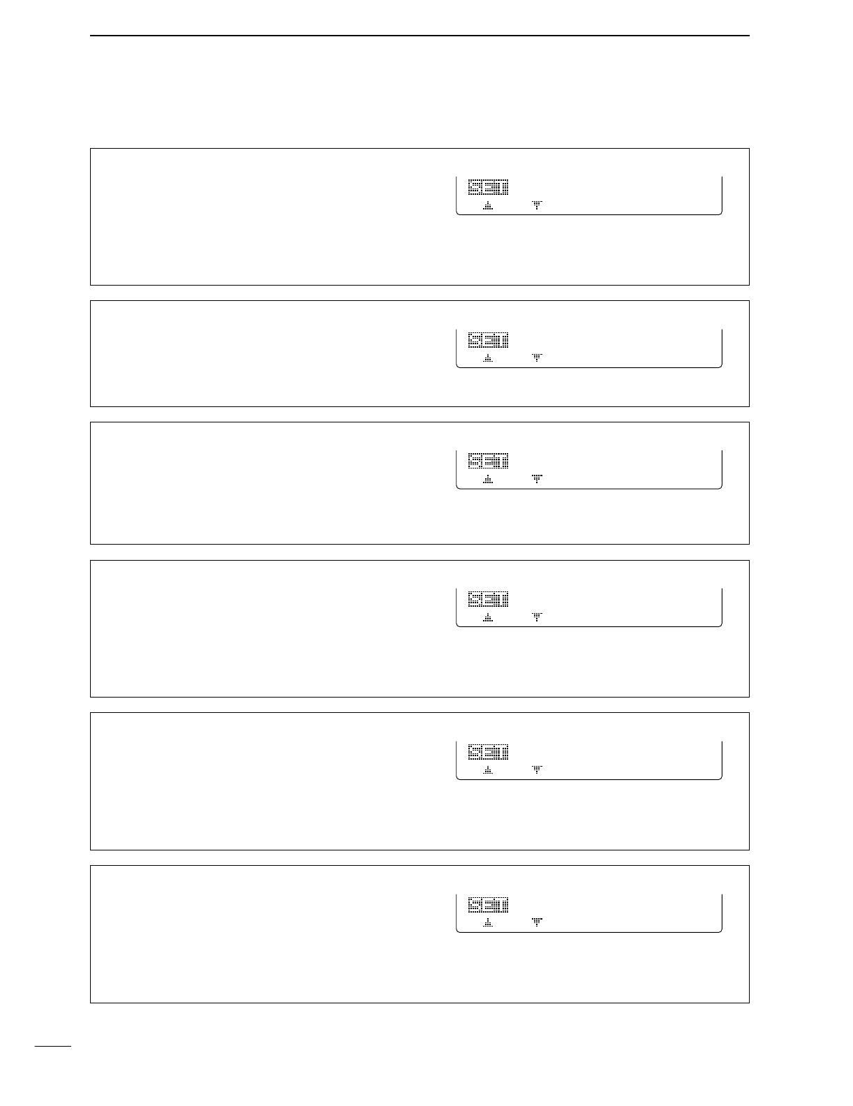
83
11 SET MODE
11. Quick SPLIT
When this item is set to ON, pushing [SPLIT] for 1
sec. sets transmit frequency using the displayed fre-
quency and the split offset, set in SPLIT Offset
item below, and activate split function automatically.
ON Quick split ON (default)
OFF Quick split OFF
11
ON
Quick
SPLIT
12. SPLIT Offset
This item sets the offset (difference between transmit
and receive frequencies) for the quick split function.
The offset frequency can be set from –9.999 MHz to
+9.999 MHz in 1 kHz steps.
12
O.OOOMHz
SPLIT
Offset
13. SPLIT LOCK
When this item is ON, the tuning dial can be used to
adjust the transmit frequency while pushing [XFC]
even while the dial lock function is activated.
ON Split lock function ON
OFF Split lock function OFF (default)
13
OFF
SPLIT
LOCK
14. DUP Offset HF
This item sets the offset (difference between transmit
and receive frequencies) for the duplex operation.
However, this setting is used to input the repeater off-
set for an HF band only.
The offset frequency can be set from 0.000 MHz to
9.999 MHz in 1 kHz steps.
14
O.1OOMHz
DUP
Offset
HF
15. DUP Offset 50M
This item sets the offset (difference between transmit
and receive frequencies) for the duplex operation.
However, this setting is used to input the repeater off-
set for a 50 MHz band only.
The offset frequency can be set from 0.000 MHz to
9.999 MHz in 1 kHz steps.
15
O.5OOMHz
DUP
Offset
5OM
■General set mode (continued)
16. DUP Offset 144M
This item sets the offset (difference between transmit
and receive frequencies) for the duplex operation.
However, this setting is used to input the repeater off-
set for a 144 MHz band only.
The offset frequency can be set from 0.000 MHz to
9.999 MHz in 1 kHz steps.
16
O.6OOMHz
DUP
Offset
144M

84
11
SET MODE
17. One Touch Rptr
This item turns the one touch repeater function to ON
(DUP- or DUP+) and OFF.
When [F2 DUP] is pushed for 1 sec. during M1, the
selected offset direction and the programmed duplex
offset frequency (depending on the operating fre-
quency band) is set with the displayed frequency.
17
DUP-
One
Touch
Rptr
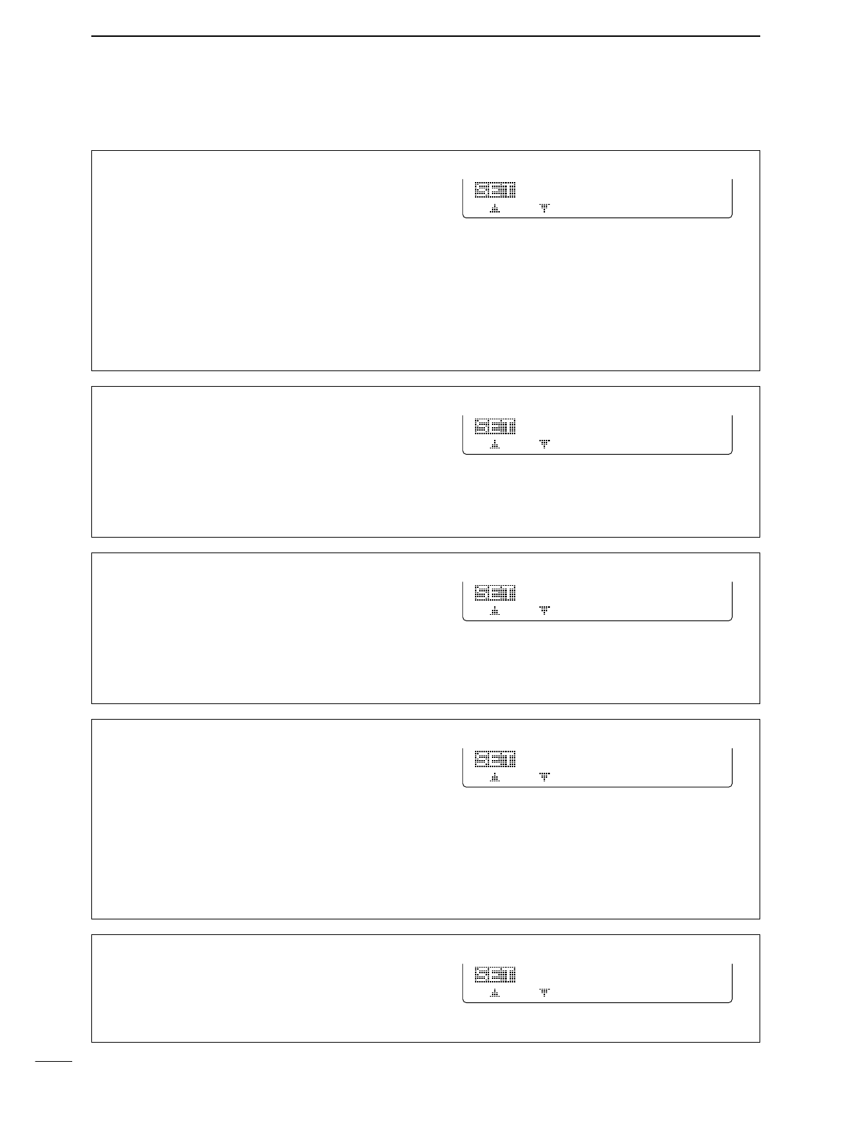
85
11 SET MODE
22. [ANT] Switch
You can set the antenna connector selection to auto-
matic, manual or non-selection (when using 1 an-
tenna only for the HF/50 MHz bands).
Auto : The antenna switch is activated and
the band memory memorizes the se-
lected antenna. (default)
Manual: The antenna switch is activated and
selects an antenna manually.
OFF : The antenna switch is not activated
and does not function. The [ANT1] con-
nector is always selected in this case.
22
Auto
[ANT]
Switch
23. SPEECH Language
When the optional UT-102
VOICE SYNTHESIZER UNIT
is
installed, you can select between English and Japan-
ese as the language.
English : Announces in English (default)
Japanese : Announces in Japanese
See p. 89 for unit installation.
23
English
SPEECH
Language
24. SPEECH Speed
When the optional UT-102
VOICE SYNTHESIZER UNIT
is
installed, you can select between faster or slower
synthesizer output.
HIGH : Announces faster (default)
LOW : Announces slower
See p. 89 for unit installation.
24
HIGH
SPEECH
Speed
25. SPEECH S-Level
When the optional UT-102
VOICE SYNTHESIZER UNIT
is
installed, you can have frequency, mode and signal
level announcement. Signal level announcement can
be deactivated if desired.
ON : Announces operating frequency, mode
and receiving signal level. (default)
OFF : Announces operating frequency and
mode only.
See p. 89 for unit installation.
25
ON
SPEECH
S-Level
26. Memory Pad Ch
This item sets the number of memo pad channels
available. 5 or 10 memo pads can be set.
5: 5 memo pads (default)
10: 10 memo pads
26
5
Memory
Pad
Ch
■General set mode (continued)
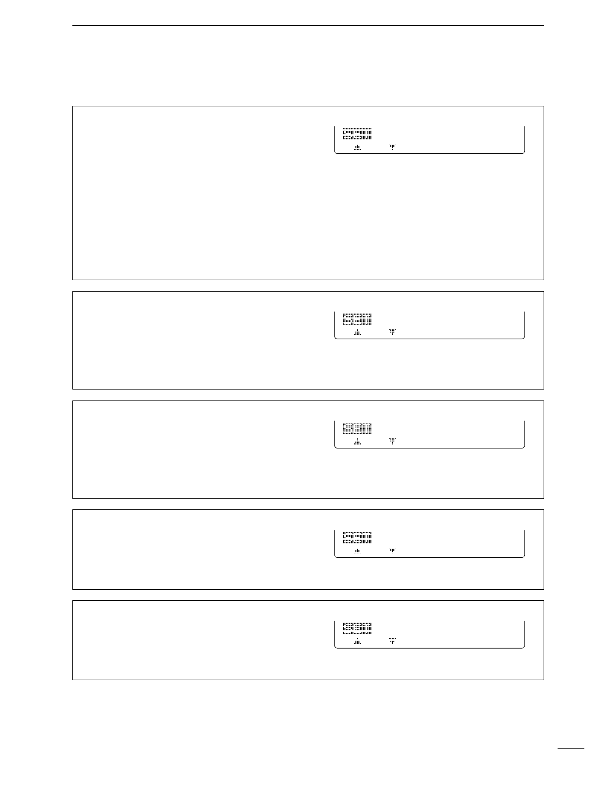
86
11
SET MODE
27. DIAL Auto TS
This item sets the auto tuning step function. When ro-
tating the tuning dial rapidly, the tuning step automat-
ically changes several times as selected.
There are 2 type of auto tuning steps: HIGH (Fastest)
and LOW (Faster).
HIGH : Auto tuning step is turned ON.
Approx. 5 times fastest tuning step
during rapid rotation (default)
LOW : Auto tuning step is turned ON.
Approx. 2 times faster tuning step dur-
ing rapid rotation
OFF : Auto tuning step is turned OFF.
27
HIGH
DIAL
Auto
TS
28. MIC U/D Speed
This item sets the rate at which frequencies are
scanned when the microphone [UP]/[DN] switches
are pushed and held. High or low can be selected.
HIGH : High speed (default, 50 tuning
steps/sec.)
LOW : Low speed (25 tuning steps/sec.)
28
HIGH
MIC
U/D
Speed
29. Quick RIT Clear
This item selects the RIT/∂TX frequency clearing in-
struction with [PBTC].
ON : Clears the RIT/∂TX frequency when
[PBTC] is pushed momentarily.
OFF : Clears the RIT/∂TX frequency when
[PBTC] is pushed for 1 sec. (default)
29
OFF
Quick
RIT
Clear
30. BW Popup (PBT)
This item turns the PBT shifting value indication ON
and OFF during [TWIN PBT] control operation. When
set to ON, the shifting value is displayed above the
multi-function switches.
(default: ON)
3O
ON
BW
Popup
(PBT)
31. BW Popup (FIL)
This item turns the IF filter width indication ON and
OFF when selecting with [FILTER]. When set to ON,
the filter width is displayed above the multi function
switches.
(default: ON)
31
ON
BW
Popup
(FIL)
■General set mode (continued)
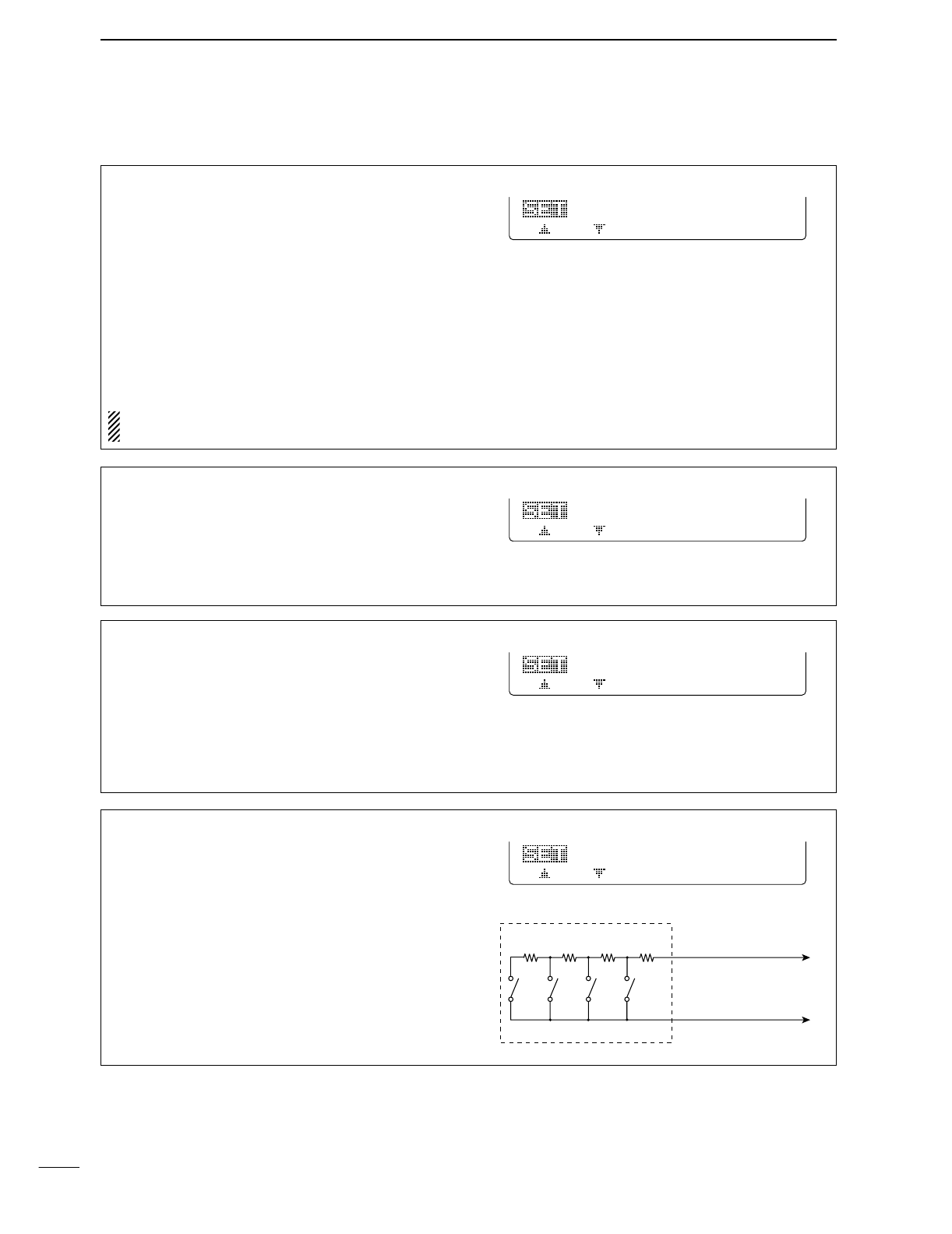
87
11 SET MODE
32. SSB/CW Synchronous Tuning
This item selects the displayed frequency shift func-
tion from ON and OFF.
When this function is activated, the receiving signal
can be kept to receive even when the operating mode
is changed between SSB and CW.
ON : The displayed frequency shifts when
the operating mode is changed be-
tween SSB and CW.
OFF : The displayed frequency does not shift.
(default)
The frequency shifting value may differ according
to the CW pitch setting.
32
OFF
SSB/CW
Sync
Tun
33. CW Normal Side
Selects the carrier point of CW mode from LSB and
USB.
LSB : The carrier point is set to LSB side.
(default)
USB : The carrier point is set to USB side.
33
LSB
CW
Normal
Side
34. KEYER 1st Menu
This item selects the appearing menu when [F4 KEY]
is pushed in M1 at first, from KEYER-Root and
KEYER-SEND.
KEYER-Root : Selects memory keyer
menu at first (default)
KEYER-SEND : Selects keyer SEND menu
at first
34 KEYER-Root
KEYER
1st
Menu
■General set mode (continued)
35. External Keypad
This item sets the external keypad capability.
OFF : External keypad does not func-
tion. (default)
KEYER SEND : Pushing one of external keypad
switches, transmits the desired
keyer memory contents during
CW mode operation.
For your information
The diagram as at right shows the equivalent circuit of
an external keypad and connects to the pin 3 and
pin 7 of the [MIC] connector (p. 12)
To [MIC] connector pin e
To [MIC] connector pin u
1.5kΩ
±5%
1.5kΩ
±5%
2.2kΩ
±5%
4.7kΩ
±5%
S1
(T1/M1)
S2
(T2/M2)
S3
(T3/M3)
S4
(T4/M4)
USER EXTERNAL KEYPAD
35
OFF
External
Keypad
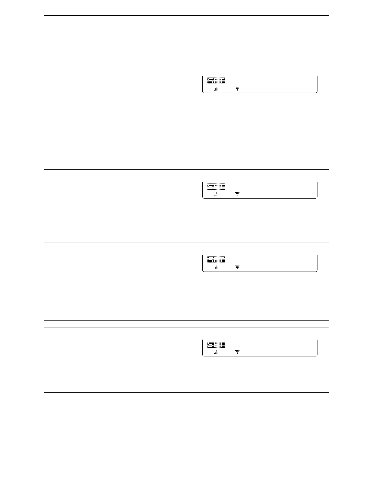
88
11
SET MODE
38. CI-V Transceive
Transceive operation is possible with the IC-746PRO
connected to other Icom HF transceivers or receivers.
ON : Transceive ON (default)
OFF : Transceive OFF
When “ON” is selected, changing the frequency, op-
erating mode, etc. on the IC-746PRO automatically
changes those of connected transceivers (or re-
ceivers) and vice versa.
38
ON
CI-V
Transceive
39. CI-V 731 Mode
When connecting the IC-746PRO to the IC-735 for
transceive operation, you must change the operating
frequency data length to 4 bytes.
•This item must be set to “ON” only when operating the
transceiver with the IC-735.
ON : 4 bytes of frequency data
OFF : 5 bytes of frequency data (default)
39
OFF
CI-V
731
Mode
■General set mode (continued)
37. CI-V Address
To distinguish equipment, each CI-V transceiver has
its own Icom standard address in hexadecimal code.
The IC-746PRO’s address is 66h.
When 2 or more IC-746PRO’s are connected to an
optional CT-17
CI
-
V LEVEL CONVERTER
, rotate the tun-
ing dial to select a different address for each IC-
746PRO in the range 01h to 7Fh.
37
66h
CI-V
Address
36. CI-V Baud Rate
This item sets the data transfer rate. 300, 1200, 4800,
9600, 19200 bps and “Auto” are available.
Auto : Auto baud rate (default)
3OO : 300 bps
12OO : 1200 bps
48OO : 4800 bps
96OO : 9600 bps
192OO : 19200 bps
When “Auto” is selected, the baud rate is automati-
cally set according to the connected controller or re-
mote controller.
36
Auto
CI-V
Baud
Rate
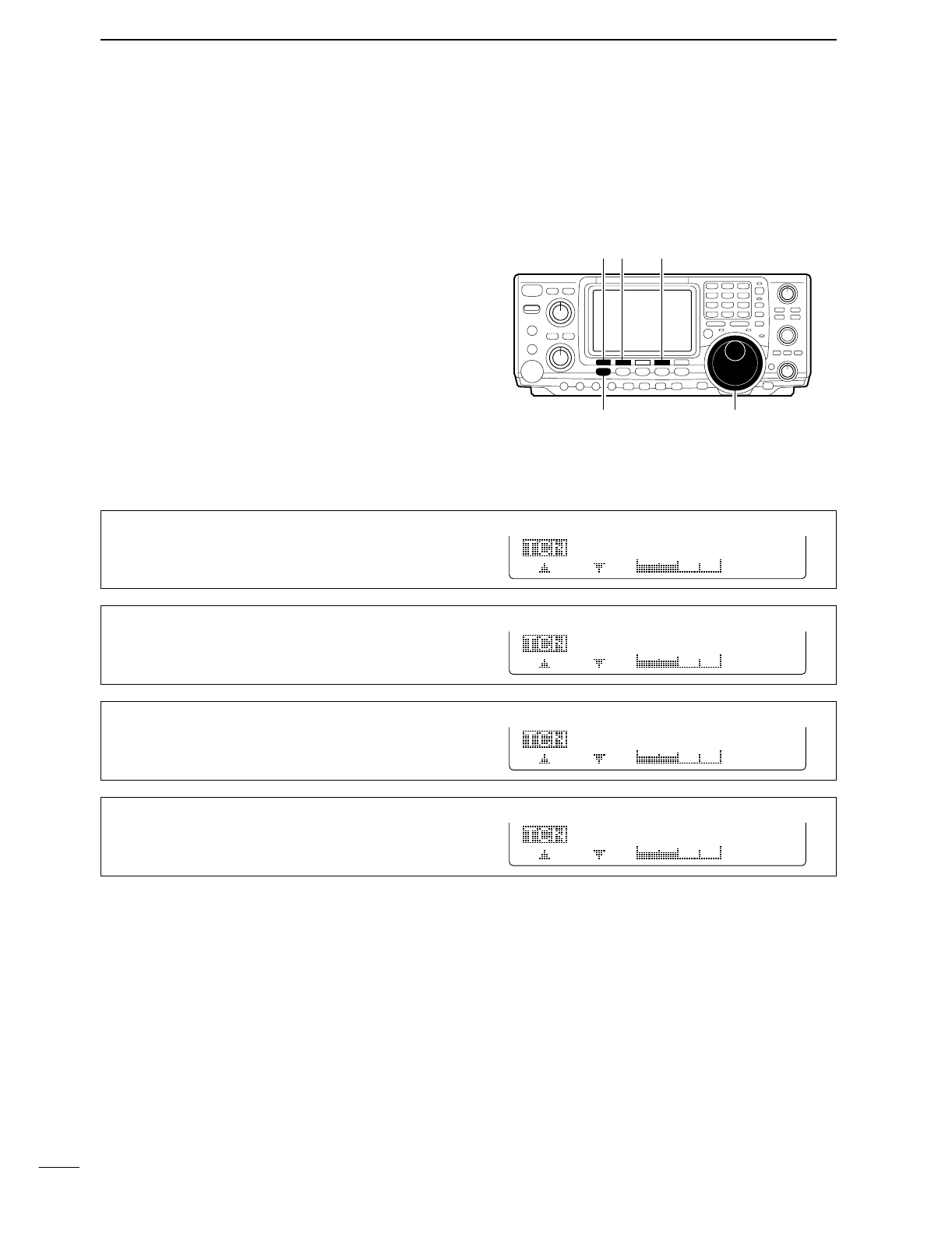
89
11 SET MODE
■Tone control set mode
DEntering tone control set mode
Tone levels (bass and treble) for each transmit and re-
ceive audio can be set for each phone mode indepen-
dently.
•Set mode operation
qPush [MENU] several times to select M2.
wPush [F4 TCN] to select the tone control set mode.
ePush [F1 ≤] or [F2 ≥] to select the desired item.
rPush [SSB] or [AM/FM] to select the desired oper-
ating mode.
tSet the desired condition using the tuning dial.
•Push [F3] for 1 sec. to select a default value.
yPush [MENU] to exit the set mode.
DTone control set mode items
[F1 ≤]
Tuning dial[MENU]
[F2 ≥] [F4 TCN]
1. TX Bass
This item adjusts the bass level of the transmit audio
tone from –5 dB to +5 dB in 1 dB steps.
TX
Bass
SSB
O
1
2. TX Treble
This item adjusts the treble level of the transmit audio
tone from –5 dB to +5 dB in 1 dB steps.
TX
Treble
SSB
O
2
3. RX Bass
This item adjusts the bass level of the receive audio
tone from –5 dB to +5 dB in 1 dB steps.
RX
Bass
SSB
O
3
4. RX Treble
This item adjusts the treble level of the receive audio
tone from –5 dB to +5 dB in 1 dB steps.
RX
Treble
SSB
O
4
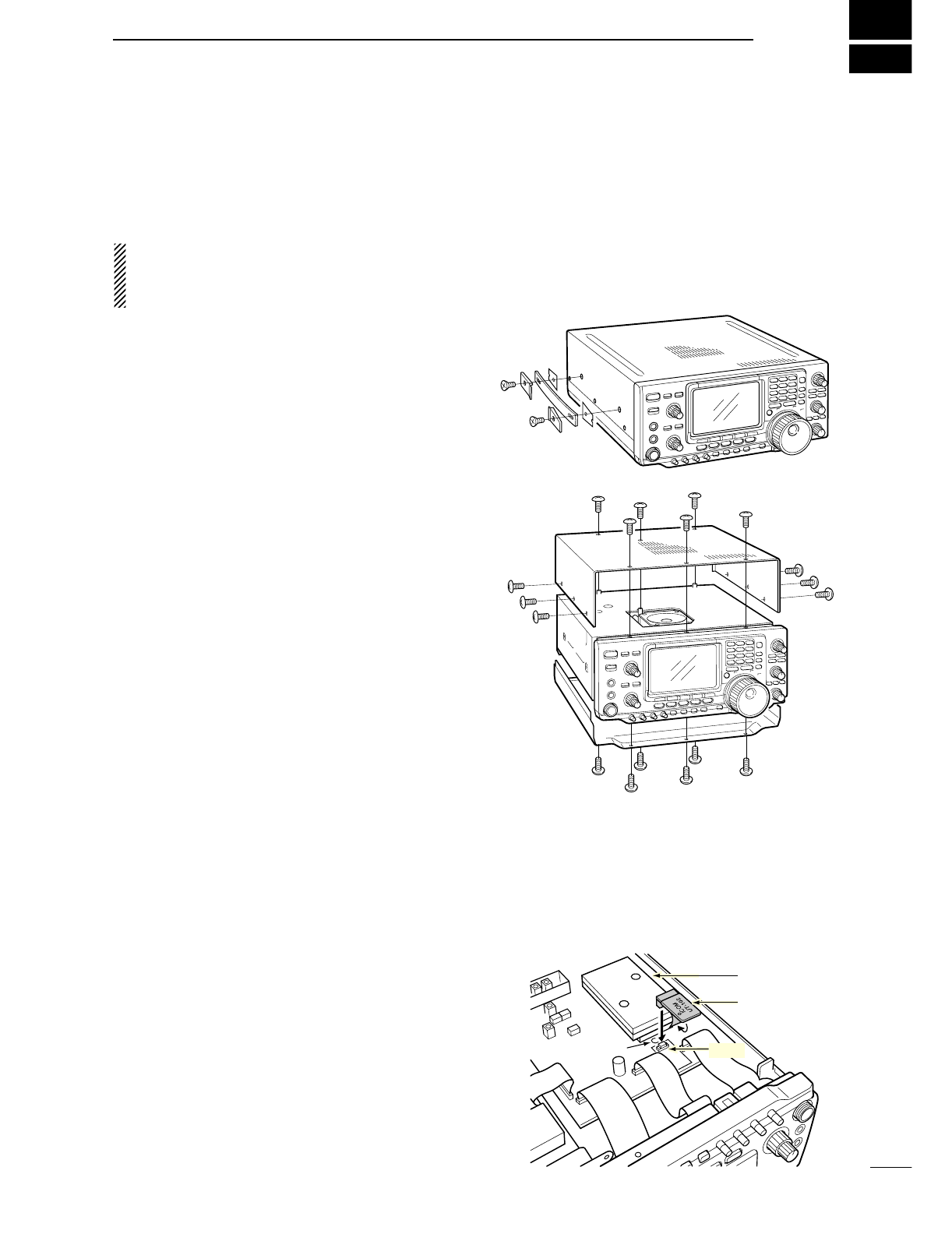
12
90
OPTION INSTALLATION
■Opening the transceiver’s case
Follow the case and cover opening procedures shown
here when you want to install an optional unit or adjust
the internal units, etc.
CAUTION: DISCONNECT the DC power cable
from the transceiver before performing any work on
the transceiver. Otherwise, there is danger of elec-
tric shock and/or equipment damage.
qRemove 2 screws from the left side of the trans-
ceiver to remove the carrying handle as shown at
right.
wRemove 6 screws from the top of the transceiver
and 6 screws from the sides, then lift up the top
cover.
eTurn the transceiver upside down.
rRemove 6 screws from the bottom of the trans-
ceiver, then lift up the bottom cover.
■UT-102
VOICE SYNTHESIZER UNIT
The UT-102 announces the accessed readout’s fre-
quency, mode, etc. (S-meter level can also be an-
nounced— p. 84) in a clear, electronically-generated
voice, in English (or Japanese).
➥Push [LOCK/SPCH] for 1 sec. to announce the fre-
quency, etc.
qRemove the top and bottom covers as shown
above.
wRemove the protective paper attached to the bot-
tom of the UT-102 to expose the adhesive strip.
ePlug UT-102 into J1920 on the MAIN unit as shown
in the diagram at right.
rAdjust the trimmer, SPCH LVL: R1925 on the MAIN
unit, to set the speech level if desired. Refer the il-
lustration at right.
tReturn the top and bottom covers to their original
positions.
MAIN unit
UT-102
J1920
R1925
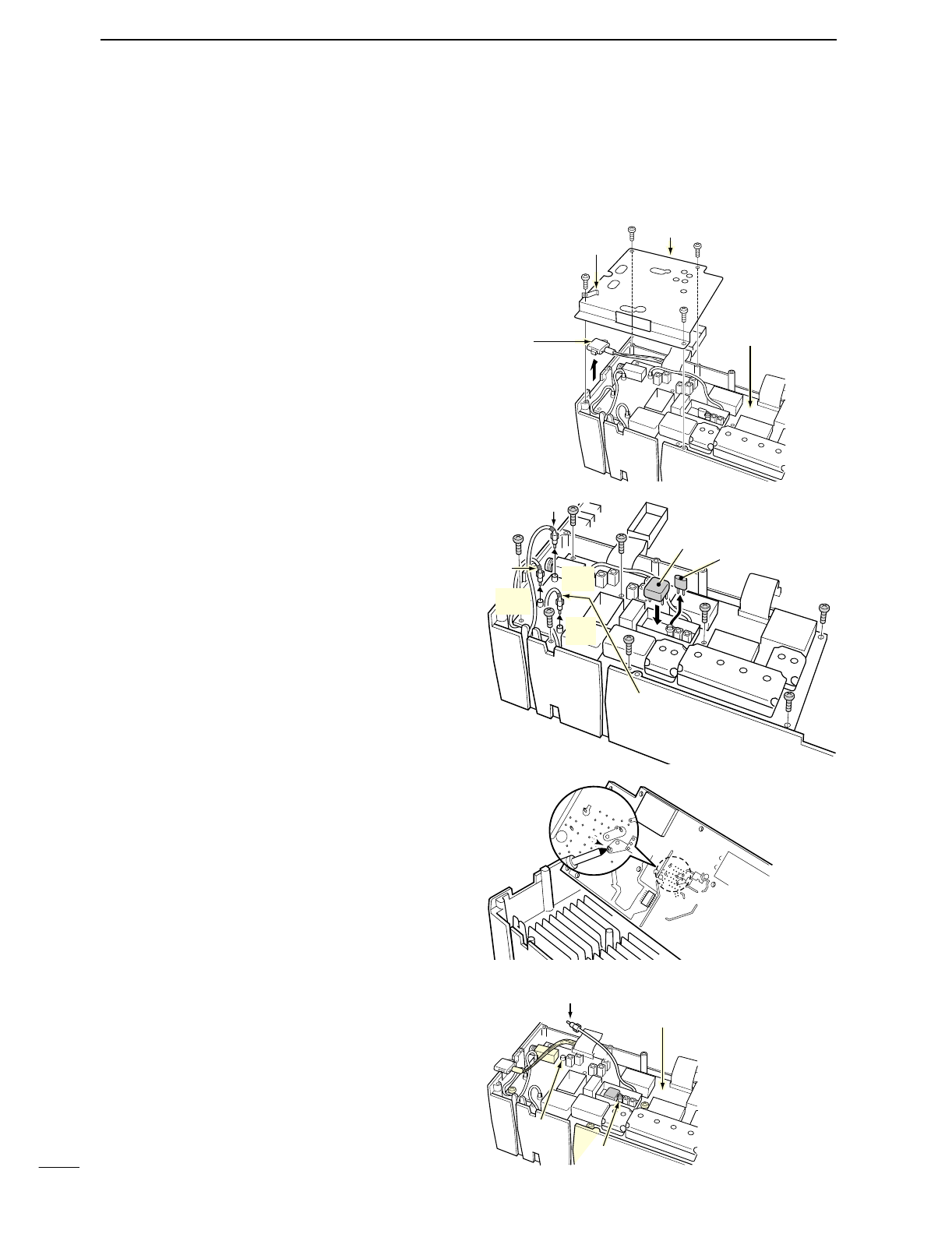
91
12 OPTION INSTALLATION
■CR-338
HIGH STABILITY CRYSTAL UNIT
By installing the CR-338, the total frequency stability
of the transceiver will be improved.
qRemove the bottom covers as shown in the previ-
ous page.
wRemove 4 screws from the shield cover of the RF
unit, then lift up the shield cover.
•There is an earth spring with the shield cover, so be
careful for lost it when removing the cover.
eRemove 8 screws from the RF unit, disconnect J1,
J121 and J151, then remove the RF unit.
rRemove the supplied internal crystal and replace
with the CR-338.
tReturn the RF unit, J1, J121 and J151 to their orig-
inal positions.
yConnect a frequency counter to the J262, 2LO IN,
then adjust the reference frequency to be
64.00000 MHz with the L1901 on the RF unit.
uReturn the J262, shield cover, earth spring and bot-
tom covers to their original positions.
Earth spring Shield cover
RF unit
TUNER
(antenna tuner)
connector
Black belt
Blue
belt
J151
Blue
J1
Black
J121
Red
CR-338
Supplied crystal
Red belt
RF unit
Soldering
points
Connect a frequency counter, then adjust
the ferquency to be 64.00000 MHz.
RF unit
J262
2LO IN
L1901

13
92
MAINTENANCE
SCAN
■Troubleshooting
The following chart is designed to help you correct
problems which are not equipment malfunctions. If you are unable to locate the cause of a problem or
solve it through the use of this chart, contact your near-
est Icom Dealer or Service Center.
PROBLEM POSSIBLE CAUSE SOLUTION REF.
RECEIVE POWER
TRANSMIT
Power does not come on
when the [POWER] switch
is pushed.
No sounds come out from
the speaker.
Sensitivity is too low, and
only strong signals are au-
dible.
Received audio is unclear
or distorted.
The [ANT] switch does not
function
Transmitting is impossible.
Output power is too low.
No contact possible with
another station.
Transmit signal is unclear
or distorted.
Repeater cannot be ac-
cessed.
Programmed scan does
not stop.
Programmed scan does
not start.
Memory scan does not
start
Select memory scan does
not start
•Power cable is improperly connected.
•Fuse is blown.
•Volume level is too low.
•The squelch is closed.
•The transceiver is in transmitting condition.
•The antenna is not connected properly.
•The antenna for another band is selected.
•The antenna is not properly tuned.
•The attenuator is activated.
•Wrong operating mode is selected.
•PBT function is activated.
•Noise blanker is turned ON when receiving a
strong signal.
•Preamp is activated.
•The noise reduction is activated and the [NR]
control is too far clockwise.
•The antenna switch has not been activated.
•The operating frequency is not set to a ham
band.
•[RF PWR] is set too far counterclockwise
•[MIC GAIN] is set too far counterclockwise
•The antenna for another band is selected.
•The antenna is not properly tuned.
•RIT or ∂TX function is activated.
•Split frequency and/or duplex function are acti-
vated.
•[MIC GAIN] is set too far clockwise
•Split frequency or duplex function is not acti-
vated.
•Programmed subaudible tone frequency is
wrong.
•Squelch is open.
•[RF/SQL] is assigned to RF gain control and
squelch is open.
•The same frequencies have been programmed
in scan edge memory channels P1 and P2.
•2 or more memory channels have not been
programmed.
•2 or more memory channels have not been
designated as select channels.
•Re-connect the DC power cable correctly.
•Check for the cause, then replace the fuse with
the spare one.
(Fuses are installed in the DC power cable and
the internal PA unit.)
•Rotate [AF] clockwise to obtain a suitable lis-
tening level.
•Turn [RF/SQL] to 10 o’clock position to open the
squelch.
•Push [TRANSMIT] to receive or check the
SEND line of an external unit, if desired.
•Re-connect to the antenna connector.
•Select an antenna suitable for the operating fre-
quency.
•Push [TUNER] for 1 sec. to manually tune the
antenna.
•
Push [P.AMP/ATT] for 1 sec. to select “ATT OFF.”
•Select a suitable operating mode.
•Push [PBTC] for 1 sec. to reset the function
•Push [NB] to turn the noise blanker OFF.
•Push [P.AMP/ATT] once or twice to turn the
function OFF.
•Set the [NR] control for maximum readability.
•Set the antenna switch in set mode to “Auto” or
“Manual.”
•Set the frequency to a ham band.
•Rotate [RF PWR] clockwise.
•Set [MIC GAIN] to a suitable position.
•Select an antenna suitable for the operating fre-
quency.
•Push [TUNER] for 1 sec. to manually tune the
antenna.
•Push [RIT] or [∂TX] to turn the function OFF.
•Push [SPLIT] and/or [F2 DUP] (in M1) to turn
the function OFF.
•Set [MIC GAIN] to a suitable position.
•Push [SPLIT] and/or [F2 DUP] (in M1) to turn
the function ON
•Reset the frequency using set mode.
•Set [RF/SQL] to the threshold point.
•Reset [RF/SQL] control assignment and set it to
the threshold point.
•Program different frequencies in scan edge
memory channel P1 and P2.
•Program more than 2 memory channels.
•Designate more than 2 memory channels as se-
lect channels for the scan.
p. 16
p. 92
p. 23
p. 24
p. 25
—
p. 75
pgs. 76,
77
p. 48
p. 23
p. 52
p. 51
p. 48
p. 53
p. 84
p. 19
p. 25
p. 25
p. 75
pgs. 76,
77
pgs. 48,
56
pgs. 58,
44
p. 25
pgs. 44,
58
p. 45
p. 24
pgs. 24,
81
p. 66
p. 63
p. 72
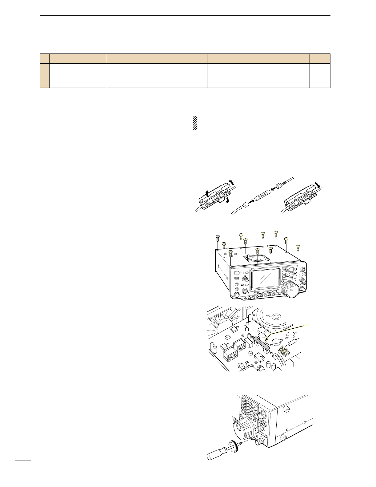
93
13 MAINTENANCE
■Fuse replacement
If a fuse blows or the transceiver stops functioning, try
to find the source of the problem, and replace the dam-
aged fuse with a new, rated fuse.
The IC-746PRO has 2 types of fuses installed for
transceiver protection.
•DC power cable fuses ................................FGB 30 A
•Circuitry fuse ................................................FGB 5 A
DDC power cable fuse replacement
Refer the figure illustrated at right for the DC power
cable fuse replacement.
DCircuitry fuse replacement
The 13.8 V DC from the DC power cable is applied to
all units in the IC-746PRO, except for the power am-
plifier, through the circuitry fuse. This fuse is installed in
the PA unit.
qRemove the top cover as shown on p. 89.
wRemove 11 screws from the PA shielding plate, then
remove the plate.
eReplace the circuitry fuse as shown in the diagram
at right.
rReplace the PA shielding plate and top cover.
■Tuning dial brake adjustment
The tension of the tuning dial may be adjusted to suit
your preference.
The brake adjustment screw is located on the right
side of the tuning dial. See the figure at right.
Turn the brake adjustment screw clockwise or counter-
clockwise to obtain a comfortable tension level while
turning the dial continuously and evenly in one direction.
PROBLEM POSSIBLE CAUSE SOLUTION REF.
DISPLAY
The displayed frequency
does not change properly.
•The dial lock function is activated.
•A set mode screen is selected.
•The internal CPU has malfunctioned.
•Push [LOCK/SPCH] to turn the function OFF.
•Push [MENU] several times to exit the set
mode.
•Reset the CPU.
p. 53
—
p. 93
30 A
fuse
Fuse
CAUTION:DISCONNECT the DC power cable
from the transceiver when changing a fuse.
Light
Heavy
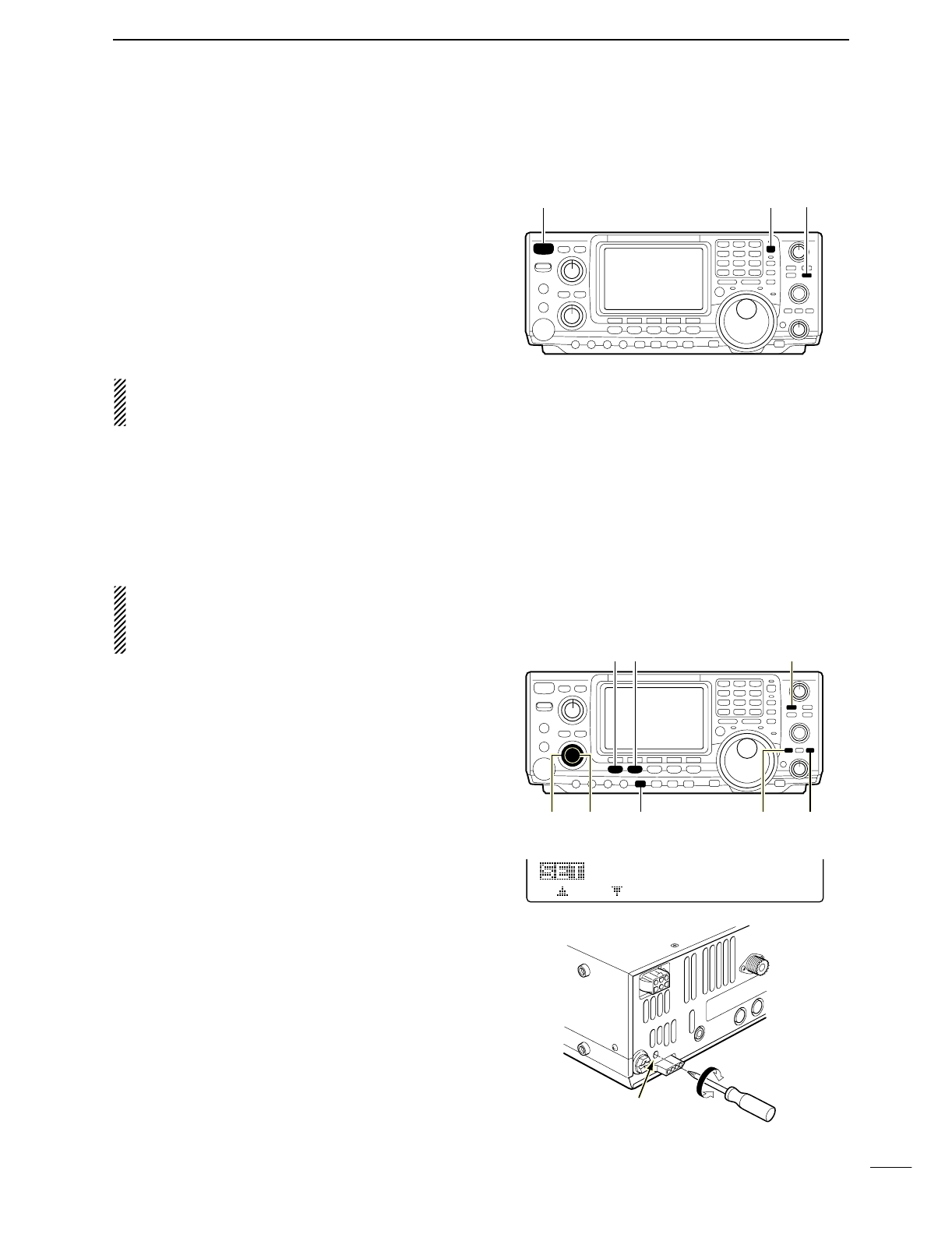
■Resetting the CPU
When first applying power or when the function seems
to be displaying erroneous information, reset the CPU
as follow:
qMake sure the transceiver power is OFF.
wWhile pushing [M-CL] and [F-INP], push [POWER]
for 1 sec. to turn power ON.
•The internal CPU is reset.
•The transceiver displays its initial VFO frequency when
resetting is complete.
eCorrect the set mode settings after resetting, if de-
sired.
NOTE: Resetting CLEARS all programmed con-
tents in memory channels and returns programmed
values in set mode to default values.
■Frequency calibration (approximate)
A very accurate frequency counter is required to cali-
brate the frequency of the transceiver. However, a
rough check may be performed by receiving radio sta-
tion WWV, or other standard frequency signals.
CAUTION: Your transceiver has been thoroughly
adjusted and checked at the factory before being
shipped. You should not calibrate frequencies, ex-
cept for special reasons.
qPush [SSB] to select USB mode.
wPush [PBTC] for 1 sec. to clear the PBT settings
and make sure that the RIT/∂TX function is not ac-
tivated.
eSet the frequency to the standard frequency station
minus 1 kHz.
•
When receiving WWV (10.000.00 MHz) as a standard
frequency, set the operating frequency for 9.999.00 MHz.
•Other standard frequencies can also be used.
rPush [MENU] several times to select M1 or M2, if
necessary.
tPush [MENU] for 1 sec. to select the set mode
screen.
yPush [F1 ≤] or [F2 ≥] several times to select the
CAL. Marker item.
uRotate the tuning dial clockwise to turn the calibra-
tion marker ON.
•Side tone may be heard.
iAdjust [CAL] pot on the rear side of the transceiver
for a zero beat with the received standard signal.
•Zero beat means that two signals are exactly the same
frequency, resulting in a single tone being emitted.
oRotate the tuning dial counterclockwise to turn the
calibration marker OFF.
!0 Push [MENU] to exit set mode.
CAL.
Marker
5
ON
[SSB][MENU] [PBTC]
[RF/SQL] [AF] [P.AMP/ATT] [CLEAR][RIT]
[CAL]
• Calibration marker item
[POWER] [F-INP] [M-CL]
94
13
MAINTENANCE
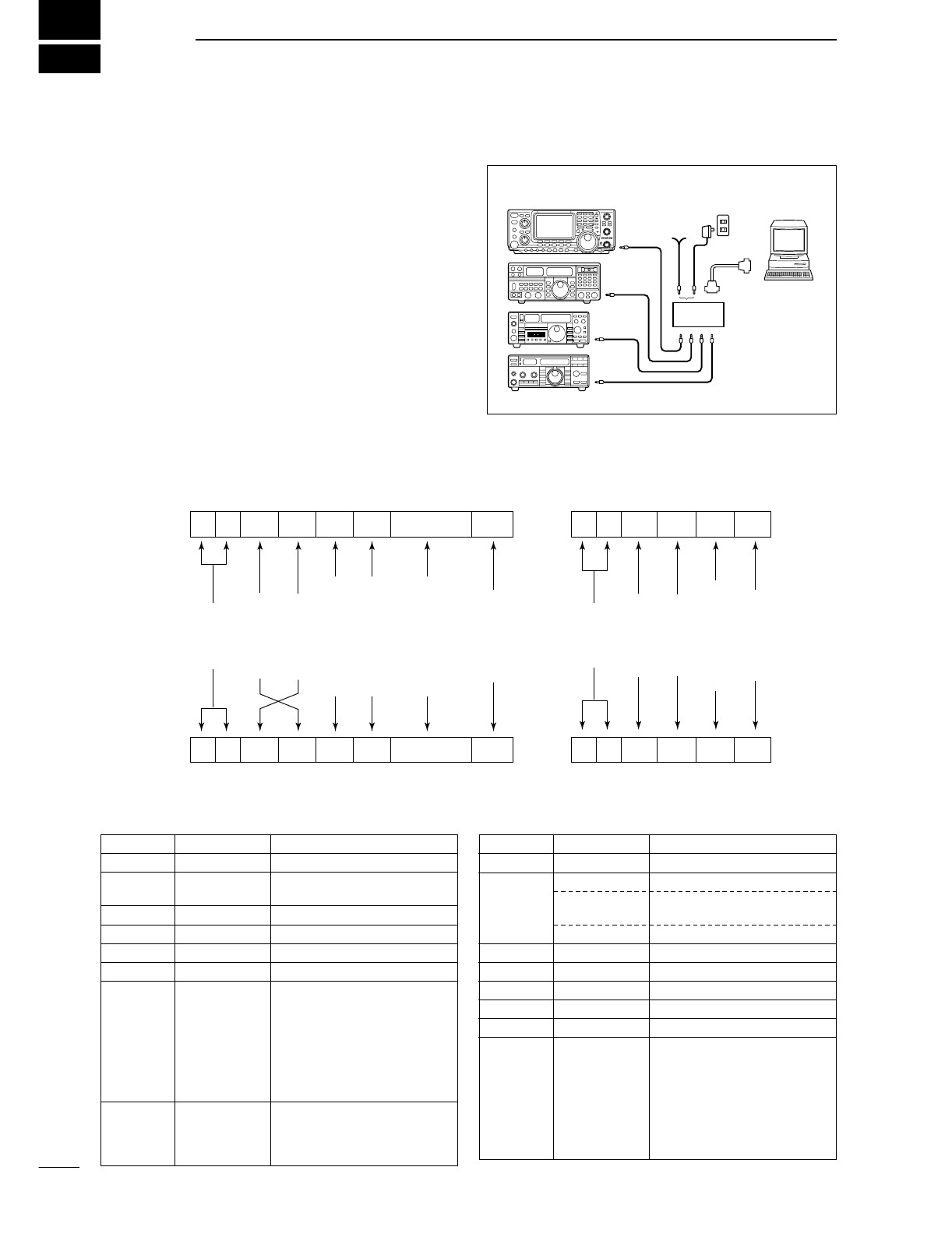
14
95
CONTROL COMMAND
•CI-V connection example
The transceiver can be connected through an optional
CT-17 CI-V LEVEL CONVERTER to a personal computer
equipped with an RS-232C port. The Icom Communi-
cations Interface-V (CI-V) controls the following func-
tions of the transceiver.
Up to 4 Icom CI-V transceivers or transceivers can be
connected to a personal computer equipped with an
RS-232C port. See p. 87 for setting the CI-V condition
using set mode.
•Data format
The CI-V system can be operated using the following
data formats. Data formats differ according to com-
mand numbers. A data area or sub command is added
for some commands.
Controller to IC-746PRO
FE FE 66 E0 Cn Sc Data area FD
Preamble
code (fixed)
Transceiver’s
default address
Controller’s
default address
Command number
(see the command table)
Sub command number
(see command table)
BCD code data for
frequency or memory
number entry
End of message
code (fixed)
OK message to controller
FE FE E0 66 FB FD
FE FE E0 66 FA FD
Preamble
code (fixed)
Controller’s
default address
Transceiver’s
default address
OK code
(fixed)
End of message
code (fixed)
NG message to controller
NG code
(fixed)
IC-746PRO to controller
qwert y u
FE FE E0 66 Cn Sc Data area FD
qwert y u
■Remote jack (CI-V) information
9–15 V
DC
personal
computer
ct- 17
BC-25
(optional)
IC-746PRO
mini-plug cable
•Command table
Command Sub command Description
00 —Send frequency data
01 Same as Send mode data
command 06
02 —Read band edge frequencies
03 —Read operating frequency
04 —Read operating mode
05 —Set operating frequency
06 00 Select LSB
01 Select USB
02 Select AM
03 Select CW
04 Select RTTY
05 Select FM
07 Select CW-R
08 Select RTTY-R
07 —Select VFO mode
00 Select VFO A
01 Select VFO B
A0 Equalize VFO A and VFO B
Command Sub command Description
07 B0 Exchange VFO A and VFO B
08 —Select memory mode
0001–0101* Select memory channel
*P1=0100, P2=0101
0102 Select the call channel
09 —Memory write
0A —Memory to VFO
0B —Memory clear
0C —Read offset frequency
0D —Set offset frequency
0E 00 Scan stop
01 Programmed/memory scan start
02 Programmed scan start
03 ∂F scan start
12 Fine programmed scan start
13 Fine ∂F scan start
22 Memory scan start
23 Select memory scan start
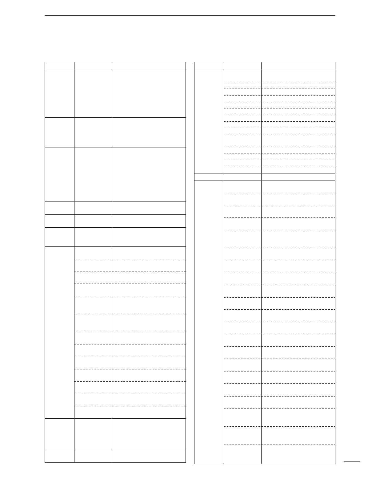
96
14
CONTROL COMMAND
•Command table (continued)
Command Sub command Description
0E A1–A7 Set ∂F scan span (A1=±5 kHz,
A2=±10 kHz, A3=±20 kHz,
A4=±50 kHz, A5=±100 kHz,
A6=±500 kHz, A7=±1 MHz)
B0 Set as non-select channel
B1 Set as select channel
D0 Set scan resume OFF
D3 Set scan resume ON
0F 00 Turn the split function OFF
01 Turn the split function ON
10 Select simplex operation
11 Select –DUP operation
12 Select +DUP operation
10 00 Select 10 Hz (1 Hz) tuning step
01 Select 100 Hz tuning step
02 Select 1 kHz tuning step
03 Select 5 kHz tuning step
04 Select 9 kHz tuning step
05 Select 10 kHz tuning step
06 Select 12.5 kHz tuning step
07 Select 20 kHz tuning step
08 Select 25 kHz tuning step
11 —Select/read attenuator (0=OFF,
1=ON)
12 —Select/read antenna selection
(0=ANT1, 1=ANT2)
13 00 Announce with voice synthesizer
01 (00=all data; 01=frequency and
02 S-meter level; 02=receive mode)
14 01 + Level data [AF] level setting (0=max. CCW to
255=max. CW)
02 + Level data [RF] level setting (0=max. CCW to
255=11 o’clock)
03 + Level data [SQL] level setting (0=11 o’clock to
255=max. CW)
06 + Level data [NR] level setting (0=min. to
255=max.)
07 + Level data Inside [TWIN PBT] setting or IF
shift setting (0=max. CCW,
128=center, 255=max. CW)
08 + Level data Outside [TWIN PBT] setting
(0=max. CCW, 128=center,
255=max. CW)
09 + Level data [CW PITCH] setting (0=300 Hz,
128=600 Hz, 255=900 Hz)
0A + Level data [RF PWR] setting (0=mini. to
255=max.)
0B + Level data [MIC GAIN] setting (0=mini. to
255=max.)
0C + Level data [KEY SPEED] setting (0=slow to
255=fast)
0D + Level data [NOTCH] setting (0=low freq. to
255=high freq.)
0E + Level data COMP Level Delay setting (0=0 to
10=10)
0F + Level data Break-IN DELAY setting (20=2.0d
to 130=13.0d)
15 01 Read squelch condition
02 Read S-meter level
11 Read RF power meter
12 Read SWR meter
13 Read ALC meter
16 02 Preamp (0=OFF; 1=preamp 1;
2=preamp 2)
Command Sub command Description
16 12 AGC selection (0=OFF; 1=Slow;
2=Mid; 3=Fast)
22 Noise blanker (0=OFF; 1=ON)
40 Noise reduction (0=OFF; 1=ON)
41 Auto notch (0=OFF; 1=ON)
42 Repeater tone (0=OFF; 1=ON)
43 Tone squelch (0=OFF; 1=ON)
44
Speech compressor (0=OFF; 1=ON)
45 Monitor (0=OFF; 1=ON)
46 VOX function (0=OFF; 1=ON)
47 Break-in (0=OFF; 1=semi break-
in; 2=full break-in)
48 Manual notch (0=OFF; 1=ON)
49 RTTY filter (0=OFF; 1=ON)
4B DTCS (0=OFF; 1=ON)
4C VSC (0=OFF; 1=ON)
19 00 Read the transceiver ID
1A 00 Send/read memory contents (see
p. 97 for details)
01 Send/read band stacking register
contents (see p. 97 for details)
02 Send/read memory keyer con-
tents (see p. 97 for details)
03 Send/read the selected filter width
(0=50 Hz to 40/31=3600/2700 Hz)
04 Send/read the selected AGC time
constant (0=OFF, 1=0.1/0.3 sec. to
13=6.0/8.0 sec.)
0501 Send/read LCD contrast (0=0% to
255=100%)
0502 Send/read LCD backlight (0=0% to
255=100%)
0503 Send/read beep gain (0=min. to
255=max.)
0504 Send/read beep gain limit (0=OFF,
1=ON)
0505 Send/read calibration marker
(0=OFF, 1=ON)
0506 Send/read confirmation beep
(0=OFF, 1=ON)
0507 Send/read band edge beep
(0=OFF, 1=ON)
0508 Send/read RF/SQL control set
(0=Auto, 1=SQL, 2=RF+SQL)
0509 Send/read meter peak hold set
(0=OFF, 1=ON)
0510 Send/read COMP meter set
(0=OFF, 1=ON)
0511 Send/read quick split set (0=OFF,
1=ON)
0512 Send/read split offset –9.999 to
+9.999 MHz (see p. 98 for details)
0513 Send/read split lock set (0=OFF,
1=ON)
0514 Send/read duplex offset 0.000 to
9.999 MHz for HF (see p. 98 for
details)
0515 Send/read duplex offset 0.000 to
9.999 MHz for 50 MHz band (see
p. 98 for details)
0516 Send/read duplex offset 0.000 to
9.999 MHz for 144 MHz band
(see p. 98 for details)
97
14 CONTROL COMMAND
•Command table (continued)
Command Sub command Description
1A 0548 Send/read FM TX Tone (Treble)
level (0=–5 to 10=+5)
0549 Send/read FM RX Tone (Bass)
level (0 =–5 to 10=+5)
0550 Send/read FM RX Tone (Treble)
level (0=–5 to 10=+5)
0551 Send/read contact number style
(0=Normal, 1=190→ANO,
2=190→ANT, 3=90→NO,
4=90→NT)
0552 Send/read count up trigger chan-
nel (1=M1, 2=M2, 3=M3, 4=M4)
0553 Send/read present number
(1–9999)
0554 Send/read CW side tone gain
(0=min. to 255=max.)
0555 Send/read CW side tone gain limit
(0=OFF, 1=ON)
0556 Send/read CW keyer repeat time
(1=1 sec. to 60=60 sec.)
0557 Send/read CW keyer dot/dash
ratio (28=1:1:2.8 to 45=1:1:4.5)
0558 Send/read rise time (0=2 msec.,
1=4 msec., 2=6 msec., 3=8 msec.)
0559 Send/read paddle polarity
(0=Normal, 1=Reverse)
0560 Send/read keyer type (0=Straight,
1=Bug-key, 2=ELEC-Key)
0561 Send/read mic. up/down keyer set
(0=OFF, 1=ON)
0562 Send/read RTTY filter bandwidth
(0=250 Hz, 1=300 Hz, 2=350 Hz,
3=500 Hz, 4=1 kHz)
0563 Send/read twin peak filter (0=OFF,
1=ON)
0564 Send/read RTTY mark frequency
(0=1275 Hz, 1=1615 Hz,
2=2125 Hz)
0565 Send/read RTTY shift width
(0=170 Hz, 1=200 Hz, 2=425 Hz)
0566 Send/read RTTY keying polarity
(0=Normal, 1=Reverse)
0567 Send/read RTTY decode USOS
(0=OFF, 1=ON)
0568 Send/read RTTY decode new line
code (0=CR,LF,CR+LF, 1=CR+LF)
0569 Send/read number of RTTY de-
coder line (0=2 lines, 1=3 lines)
0570 Send/read scan speed (0=Low,
1=High)
0571 Send/read scan resume (0=OFF,
1=ON)
0572 Send/read NB level (0=0% to
255=100%)
0573 Send/read VOX gain (0=0% to
255=100%)
0574 Send/read anti VOX gain (0=0% to
255=100%)
0575 Send/read VOX delay (0=0.0 sec.
to 20=2.0 sec.)
0576 Send/read Break-IN delay set
(20=2.0d to 130=13.0d)
Command Sub command Description
1A 0517 Send/read one touch repeater set
(0=DUP–, 1=DUP+)
0518 Send/read auto repeater set
(0=OFF, 1=ON-1, 2=ON-2)
0519 Send/read tuner auto start set
(0=OFF, 1=ON)
0520 Send/read PTT tune set (0=OFF,
1=ON)
0521 Send/read 9600 bps mode set
(0=OFF, 1=ON)
0522 Send/read antenna selection
(0=OFF, 1=Manual, 2=Auto)
0523 Send/read speech language
(0=English, 1=Japanese)
0524 Send/read speech speed (0=Slow,
1=Fast)
0525 Send/read S-level speech (0=OFF,
1=ON)
0526 Send/read memo pad numbers
(0=5 ch, 1=10 ch)
0527 Send/read main dial auto TS
(0=OFF, 1=Low, 2=High)
0528 Send/read mic. up/down speed
(0=Low, 1=High)
0529 Send/read quick RIT/∂TX clear
function (0=OFF, 1=ON)
0530 Send/read PBT shifting value
popup set (0=OFF, 1=ON)
0531 Send/read IF filter width popup
set (0=OFF, 1=ON)
0532 Send/read SSB/CW synchronous
tuning function (0=OFF, 1=ON)
0533 Send/read CW normal side set
(0=LSB, 1=USB)
0534 Send/read keyer 1st menu set
(0=Keyer-root, 1=Keyer-send)
0535 Send/read external keypad set
(0=OFF, 1=Keyer send)
0536 Send/read CI-V transceive set
(0=OFF, 1=ON)
0537 Send/read CI-V 731 mode set
(0=OFF, 1=ON)
0538 Send/read speech compressor
level set (0=0 to 10=10)
0539 Send/read SSB TX Tone (Bass)
level (0 =–5 to 10=+5)
0540 Send/read SSB TX Tone (Treble)
level (0=–5 to 10=+5)
0541 Send/read SSB RX Tone (Bass)
level (0 =–5 to 10=+5)
0542 Send/read SSB RX Tone (Treble)
level (0=–5 to 10=+5)
0543 Send/read AM TX Tone (Bass)
level (0 =–5 to 10=+5)
0544 Send/read AM TX Tone (Treble)
level (0=–5 to 10=+5)
0545 Send/read AM RX Tone (Bass)
level (0 =–5 to 10=+5)
0546 Send/read AM RX Tone (Treble)
level (0=–5 to 10=+5)
0547 Send/read FM TX Tone (Bass)
level (0 =–5 to 10=+5)
98
14
CONTROL COMMAND
•Command table (continued)
DTo send/read memory contents
When sending or reading memory contents, additional code
as follows must be added to appoint the memory channel.
➥Additional code: 0000–0102 (0100=P1, 0101=P2, 0102=Call)
DBand stacking register
To send or read the desired band stacking register’s con-
tents, combined code of the frequency band and register
codes as follows are used.
For example, when sending/reading the oldest contents in
the 21 MHz band, the code “0703” is used.
•Frequency band code
•Register code
DCodes for memory keyer contents
To send or read the desired memory keyer contents, the
channel and character codes as follows are used.
•Channel code
•Character’s code
DCodes for memory name contents
To send or read the desired memory name settings, the char-
acter codes, instructed codes for memory keyer contents as
above, and follows are additionally used.
•Character’s code— Alphabetical characters
•Character’s code— Symbols
Character ASCII code Character ASCII code
a–z61–7A ——
Code Frequency band Frequency range (unit: MHz)
01 1.8 1.800000–1.999999
02 3.5 3.400000–4.099999
03 7 6.900000–7.499999
04 10 9.900000–10.499999
05 14 13.900000–14.499999
06 18 17.900000–18.499999
07 21 20.900000–21.499999
08 24 24.400000–25.099999
09 28 28.000000–29.999999
10 50 50.000000–54.000000
11 144 144.000000–148.000000
12 GENE Other than above
Code Registered number
01 1 (latest)
02 2
03 3 (oldest)
Character ASCII code Description
0–930–39 Numerals
A–Z41–5A Alphabetical characters
space 20 Word space
/ 2F Symbol
? 3F Symbol
, 2C Symbol
. 2E Symbol
^ 5E e.g., to send
BT
, enter ^4254
✱2A Inserts contact number (can be
used for 1 channel only)
Code Channel number
01 M1
02 M2
03 M3
04 M4
Command Sub command Description
1A 0577 Send/read MONITOR level (0=0%
to 255=100%)
06 Send/read DATA mode (0=OFF,
1=ON)
07 Send/read SSB transmit band-
width (0=WIDE, 1=MID, 2=NAR)
08 Send/read DSP filter shape
(0= sharp, 1= soft)
1B 00 Set/read repeater tone frequency
(see p. 98 for details)
01 Set/read TSQL tone frequency
(see p. 98 for details)
02 Set/read DTCS code and polarity
(see p. 98 for details)
1C 00 Set/read the transceiver’s condi-
tion (0=Rx; 1=Tx)
01 Set/read antenna tuner condition
(0=OFF, 1=ON, 2=Start tuning or
while tuning)
Character ASCII code Character ASCII code
!21#23
$24%25
&26¥5C
?3F”22
’27`60
+2B–2D
:3A;3B
=3D<3C
>3E( 28
)29[5B
]5D{7B
}7D|7C
_5F–7E
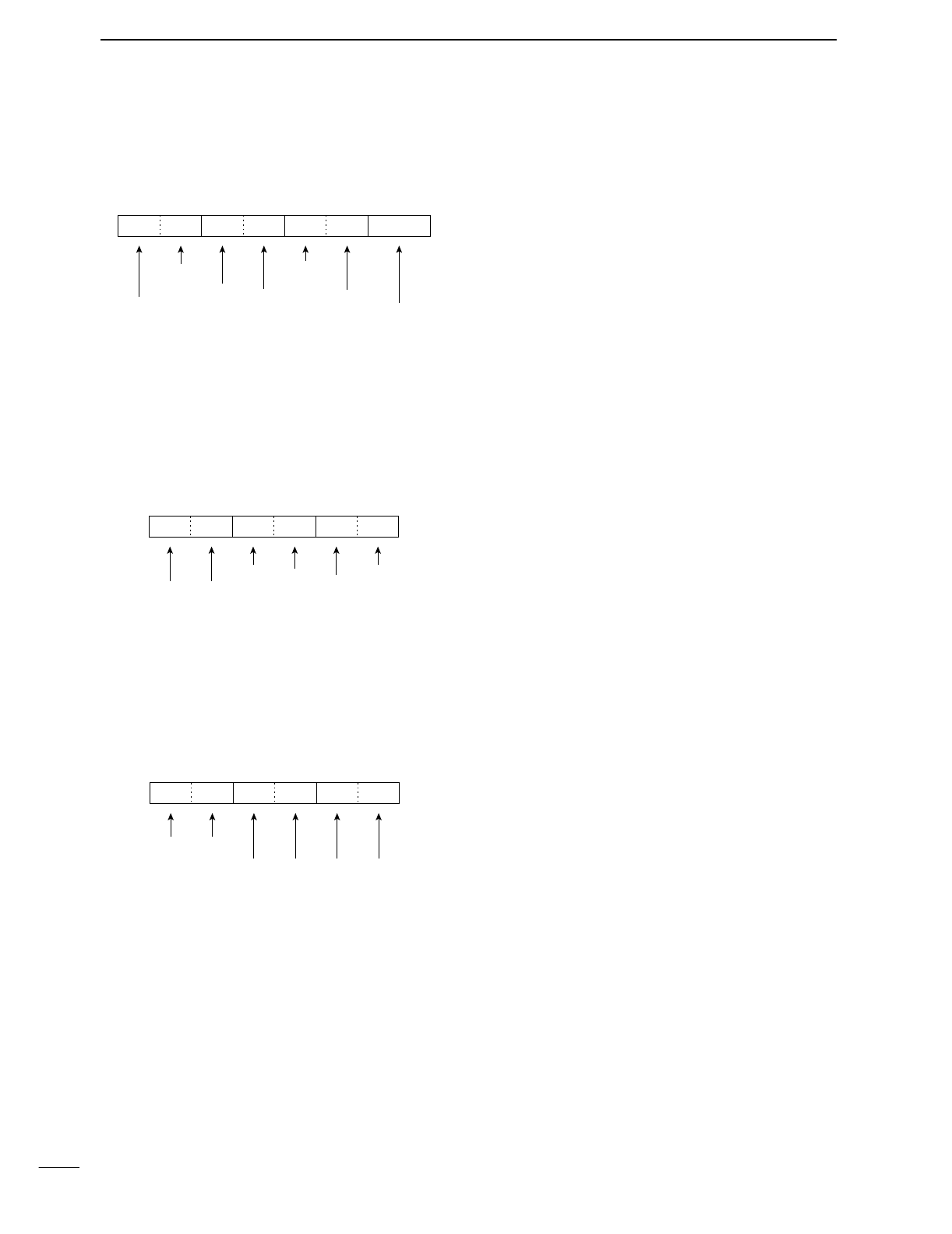
DSplit/Duplex frequency setting
The following data sequence is used when sending/reading
the split or duplex frequency setting.
DRepeater tone/tone squelch frequency setting
The following data sequence is used when sending/reading
the DTCS code and polarity setting.
DDTCS code and polarity setting
The following data sequence is used when sending/reading
the DTCS code and polarity setting.
Fixed digit: 0
1st digit: 0–7
2nd digit: 0–7
3rd digit: 0–7
Transmit polarity:
0= Normal
1= Reverse
Receive polarity:
0= Normal
1= Reverse
q
XX0XX
we
X
100Hz digit: 0–2
10 Hz digit: 0–9
1 Hz digit: 0–9
0.1 Hz digit: 0–9
Fixed digit: 0*
Fixed digit: 0*
q*
00XXX
we
X
*Not necessary when setting a frequency.
1 kHz digit: 0–9
100 Hz digit: 0 (fixed)
100 kHz digit: 0–9
10 kHz digit: 0–9
10 MHz digit: 0 (fixed)
1 MHz digit: 0–4
Direction:
00=+ direction
01=– direction
q
0XXXXXX
we
0
r*
*Not need to enter for duplex frqeuency setting.
99
14 CONTROL COMMAND

15
100
SPECIFICATIONS
•General
•Frequency coverage : (Unit: MHz)
Receive 0.030–60.000000*
108.000–174.000000*
Transmit 1.800–2.000000
3.500–3.999999
7.000–7.300000
10.100–10.150000
14.000–14.350000
18.068–18.168000
21.000–21.450000
24.890–24.990000
28.000–29.700000
50.000–54.000000
144.000–148.000000
*Some frequency ranges are not guaranteed.
•Mode : USB, LSB, CW, RTTY, AM, FM
•No. of memory ch. : 102 (99 regular, 2 scan edges and 1
call)
•Antenna connector : SO-239×3 (2 for HF/50 MHz and 1
for 144 MHz; 50 Ω)
•Usable temp. range : –10˚C to +60˚C ; +14˚F to +140˚F
•Frequency stability : Less than ±7 ppm from 1 min. to
60 min. after power ON. After
that, rate of stability is less than
±1 ppm/hr. at 25˚C (+77˚F).
Temperature fluctuations 0˚C to
+50˚C (+20˚F to +122˚F) less than
±5 ppm.
•Frequency resolution : 1 Hz
•Power supply : 13.8 V DC ±15% (negative ground)
•Power consumption :
Transmit Max. power 23.0 A
Receive Standby 2.2 A
Max. audio 3.0 A
•Dimensions : 287(W)×120(H)×316.5(D) mm
(projections not incl.)
13
5
⁄
16
(W)×4
23
⁄
32
(H)×12
15
⁄
32
(D) in
•Weight (approx.) : 9.0 kg; 19 lb 13 oz
•ACC 1 connector : 8-pin DIN connector
•ACC 2 connector : 7-pin DIN connector
•DATA connector : Mini DIN 6-pin
•CI-V connector : 2-conductor 3.5 (d) mm (1⁄8″)
•Transmitter
•Output power (continuously adjustable):
SSB/CW/RTTY/FM Less than 5 to 100 W
AM Less than 5 to 40 W
•Modulation system :
SSB
Digital PSN modulation
AM
Digital low power modulation
FM
Digital phase modulation
•Spurious emission : 50 dB (HF bands)
60 dB (50/144 MHz)
•Carrier suppression : 40 dB
•Unwanted sideband : 55dB
suppression
•∂TX variable range : ±9.99 kHz
•Mic. connector : 8-pin connector (600 Ω)
•
ELEC-KEY connector
:
3-conductor 6.35(d) mm
(1⁄4″)
•KEY connector :
3-conductor 6.35(d) mm
(1⁄4″)
•SEND connector : Phono (RCA)
•ALC connector : Phono (RCA)
•Receiver
•Receive system : Triple conversion
superheterodyne system
•Intermediate frequencies:
1st 64.455 MHz
2nd 455 kHz
3rd 36 kHz
•Sensitivity (typical) :
SSB, CW, RTTY 0.16 µV*1(1.80–29.99 MHz)
(10 dB S/N) 0.13 µV*2(50 MHz)
0.11 µV*3(144 MHz)
AM (10 dB S/N) 13 µV (0.5–1.799 MHz)
2 µV*1(1.80–29.99 MHz)
1 µV (50*2/144*3MHz)
FM (12 dB SINAD) 0.5 µV*1(28.0–29.99 MHz)
0.25 µV*2(50 MHz)
0.18 µV*3(144 MHz)
*1Pre-amp 1 is ON, *2Pre-amp 2 is ON, *3Pre-amp is ON
•Squelch sensitivity (Pre-amp: OFF):
SSB, CW, RTTY Less than 5.6 µV
FM Less than 1.0 µV
•Selectivity :
SSB (BW: 2.4 kHz) More than 2.4 kHz/–6 dB
Less than 3.6 kHz/–60 dB
CW (BW: 500 Hz) More than 500 Hz/–6 dB
Less than 700 Hz/–60 dB
RTTY (BW: 350 Hz) More than 360 Hz/–6 dB
Less than 650 Hz/–60 dB
AM (BW: 6 kHz) More than 6.0 kHz/–6 dB
Less than 15.0 kHz/–60 dB
FM (BW: 15 kHz) More than 12.0 kHz/–6 dB
Less than 20.0 kHz/–60 dB
•Spurious and image rejection ratio:
HF/50 MHz More than 70 dB (except IF through
on 50 MHz band)
144 MHz More than 60 dB
•AF output power : More than 2.0 W at 10% distortion
(at 13.8 V DC) with an 8 Ωload
•RIT variable range : ±9.99 kHz
•PHONES connector : 3-conductor 6.35 (d) mm (1⁄4″)
•Ext. SP connector : 2-conductor 3.5 (d) mm (1⁄8″)/8Ω
•Antenna tuner
•Matching impedance range:
HF bands 16.7 to 150 Ωunbalanced
(Less than VSWR 3:1)
50 MHz band 20 to 125 Ωunbalanced
(Less than VSWR 2.5:1)
•Minimum operating input power
:8 W (HF bands)
15 W (50 MHz band)
•Tuning accuracy : VSWR 1.5:1 or less
•Insertion loss : Less than 1.0 dB (after tuning)
All stated specifications are typical and subject to change without no-
tice or obligation.
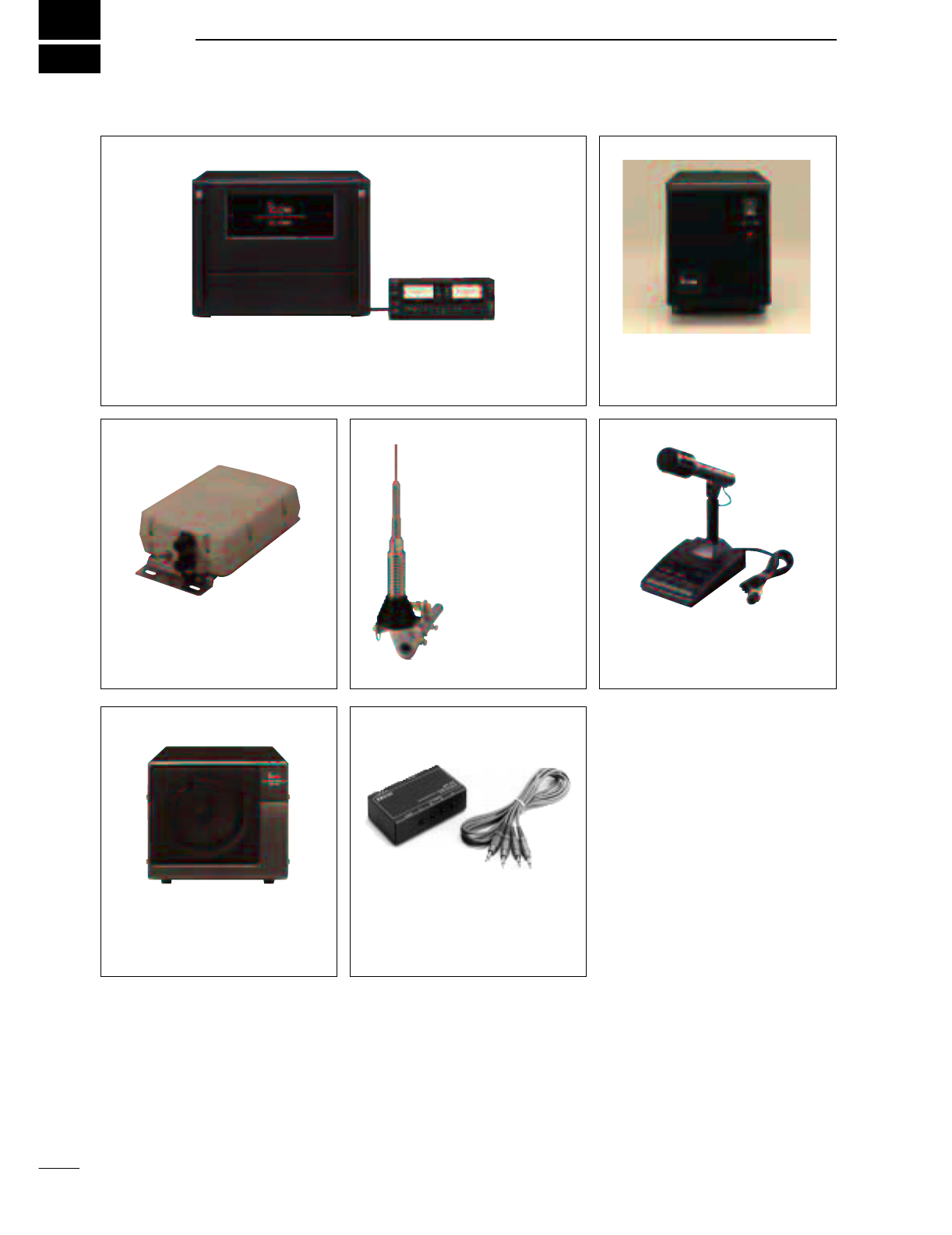
16
101
OPTIONS
IC-PW1 HF/50 MHz ALL BAND 1 kW LINEAR AMPLIFIER
Full-duty 1 kW linear amplifier including an automatic antenna tuner. Has
automatic tuning and band selection capability. Full break-in (QSK) oper-
ation is possible. The amplifier/power supply unit and the remote control
unit are separated.
AH-4 HF/50 MHz AUTOMATIC
ANTENNA TUNER
Specially designed to tune a long
wire antenna for portable or mobile
HF operation. The PTT tuner start
function provides simple operation.
•Input power rating: 120 W
AH-2b ANTENNA ELEMENT
A 2.5 m long an-
tenna element for
mobile operation
with the AH-4.
•Frequency
coverage:
7–54 MHz bands
with the AH-4
SM-20 DESKTOP MICROPHONE
Unidirectional, electret microphone
for base station operation. Includes
[UP]/[DOWN] switches and a low
cut function.
SP-21 EXTERNAL SPEAKER
Designed for base station opera-
tion.
•Input impedance: 8 Ω
•Max. input power: 5 W
CT-17 CI-V LEVEL CONVERTER
For remote transceiver control
using a personal computer. You
can change frequencies, operating
mode, memory channels, etc.
UT-102 VOICE SYNTHESIZER UNIT
Announces the receive frequency, mode
and S-meter level in a clear, electroni-
cally-generated voice, in English (or
Japanese).
SP-20 EXTERNAL SPEAKER
4 audio filters; headphone jack; can con-
nect to 2 transceivers.
•Input impedance: 8 Ω
•Max. input power: 5 W
CR-338 HIGH STABILITY CRYSTAL
UNIT
Contains a temperature-compensating
oven heater and crystal unit for improved
frequency stability.
•Frequency stability: ±0.5 ppm
HM-36 HAND MICROPHONE
Hand microphone equipped with
[UP]/[DOWN] switches.
PS-125 DC POWER SUPPLY
Light weight switching regulator
system power supply.
•Output voltage: 13.8 V DC
•Max. current drain: 25 A

1-1-32 Kamiminami, Hirano-ku, Osaka 547-0003 Japan
A-6085H-1EX
Printed in Japan
© 2001 Icom Inc.