ICOM orporated IC-746PRO Amateur HF \ VHF Scanning Transceiver User Manual 746PRO INSTRUCTION MANUAL EN pd
ICOM Incorporated Amateur HF \ VHF Scanning Transceiver 746PRO INSTRUCTION MANUAL EN pd
Contents
- 1. Manual Part 1
- 2. Manual Part 2
Manual Part 1

HF/VHF
ALL MODE TRANSCEIVER
i746PRO
INSTRUCTION MANUAL
This device complies with Part 15 of the FCC rules. Operation is sub-
ject to the following two conditions: (1) This device may not cause
harmful interference, and (2) this device must accept any interference
received, including interference that may cause undesired operation.

i
FOREWORD
We understand making you have a choice of many dif-
ferent radios in the market place.I want to take a cou-
ple of moments of your time to thank you for making
your IC-746PRO your radio of choice, and hope you
agree with Icom’s philosophy of “technology first”.Many
hours of research and development went into the de-
sign of your IC-746PRO.
Rather than completely redesigning all areas to create
a new radio, the engineering team at Icom decided to
follow in the footsteps of the IC-746 (one of the best
values in the marketplace) with the new “PRO”. Fo-
cused on real world improvements compiled over the
last few years from letters, phone calls, E-Mails and
newsgroup postings the engineering team at Icom is
proud to say “many of these changes were compiled
from a list of suggestions from you, the amateur radio
operator!”
FEATURES
•32-bit Floating point DSP and 24-bit AD/DA converter
•DSP IF Filter creates 102 types of filter types
•All mode capability covering 160–2 m
•100 Watt continuous duty cycle
•All mode digital modulation and demodulation
•RTTY demodulator and decoder
•Twin Pass Band Tuning
•RF speech compression with selectable pass band
•Microphone Equalizer
•SSB/CW synchronous tuning
EXPLICIT DEFINITIONS
READ THIS INSTRUCTION MANUAL
CAREFULLY before attempting to operate the
transceiver.
SAVE THIS INSTRUCTION MANUAL. This
manual contains important safety and operating in-
structions for the IC-746PRO.
EXPLICIT DEFINITIONS
PRECAUTIONS
RWARNING RF EXPOSURE! This device emits
Radio Frequency (RF) energy. Extreme caution should be
observed when operating this device. If you have any
questions regarding RF exposure and safety standards
please refer to the Federal Communications Commission
Office of Engineering and Technology’s report on Evalu-
ating Compliance with FCC Guidelines for Human Radio
frequency Electromagnetic Fields (OET Bulletin 65).
RWARNING HIGH VOLTAGE! NEVER attach an
antenna or internal antenna connector during transmis-
sion. This may result in an electrical shock or burn.
RNEVER apply AC to the [DC13.8V] jack on the trans-
ceiver rear panel. This could cause a fire or ruin the trans-
ceiver.
RNEVER apply more than 16 V DC, such as a 24 V
battery, to the [DC13.8V] jack on the transceiver rear
panel. This could cause a fire or ruin the transceiver.
RNEVER let metal, wire or other objects touch any in-
ternal part or connectors on the rear panel of the trans-
ceiver. This may result in an electric shock.
NEVER expose the transceiver to rain, snow or any liquids.
AVOID using or placing the transceiver in areas with tem-
peratures below –10°C (+14°F) or above +50°C (+122°F).
Be aware that temperatures on a vehicle’s dashboard can
exceed 80°C (+176°F), resulting in permanent damage to
the transceiver if left there for extended periods.
AVOID placing the transceiver in excessively dusty envi-
ronments or in direct sunlight.
AVOID placing the transceiver against walls or putting
anything on top of the transceiver. This will obstruct heat
dissipation.
Place unit in a secure place to avoid inadvertent use by
children.
During mobile operation, DO NOT operate the transceiver
without running the vehicle’s engine. When transceiver
power is ON and your vehicle’s engine is OFF, the vehi-
cle’s battery will soon become exhausted.
Make sure the transceiver power is OFF before starting
the vehicle. This will avoid possible damage to the trans-
ceiver by ignition voltage spikes.
During maritime mobile operation, keep the transceiver
and microphone as far away as possible from the magnetic
navigation compass to prevent erroneous indications.
BE CAREFUL! The heatsink will become hot when oper-
ating the transceiver continuously for long periods.
BE CAREFUL! If a linear amplifier is connected, set the
transceiver’s RF output power to less than the linear am-
plifier’s maximum input level, otherwise, the linear ampli-
fier will be damaged.
Use Icom microphones only (supplied or optional). Other
manufacturer’s microphones have different pin assign-
ments, and connection to the IC-746PRO may damage
the transceiver.
WORD DEFINITION
RWARNING Personal injury, fire hazard or electric
shock may occur.
CAUTION Equipment damage may occur.
NOTE
If disregarded, inconvenience only. No
risk or personal injury, fire or electric
shock.

ii
SUPPLIED ACCESSORIES
The transceiver comes with the following accessories.
Qty.
qDC power cable (OPC-025D) ............................ 1
wHand microphone (HM-36) ................................ 1
eSpare fuses (FGB 30 A) .................................... 2
rSpare fuse (FGB 5 A) ........................................ 1
tCW keyer plug (AP-330) .................................... 1
TABLE OF CONTENTS
qw
ert
FOREWORD ........................................ i
IMPORTANT ........................................ i
EXPLICIT DEFINITIONS ..................... i
PRECAUTIONS ................................... i
TABLE OF CONTENTS ...................... ii
QUICK REFERENCE GUIDE ........ I–X
■Installation ....................................... I
■Operation ....................................... III
■Your first contact ........................... IV
■Ready to call CQ? ......................... IX
1 PANEL DESCRIPTION ........... 1–12
■Front panel ..................................... 1
■Rear panel ...................................... 7
■LCD display .................................... 9
■Multi function switches .................. 11
■Microphone (HM-36) .................... 12
2 INSTALLATION AND
CONNECTIONS ................... 13–17
■Unpacking .................................... 13
■Selecting a location ...................... 13
■Grounding ..................................... 13
■Antenna connection ...................... 13
■Required connections ................... 14
■Advanced connections ................. 15
■Power supply connections ............ 16
■Linear amplifier connections ......... 17
■External antenna tuner
connection .................................... 17
3 BASIC OPERATION ............. 18–25
■When first applying power
(CPU resetting) ............................. 18
■Initial settings ................................ 18
■Selecting an operating band ........ 19
■Selecting VFO/memory mode ...... 20
■VFO operation .............................. 20
■Frequency setting ......................... 21
■Operating mode selection ............ 23
■Volume setting .............................. 23
■Squelch and receive (RF)
sensitivity ...................................... 24
■Basic transmit operation ............... 25
4 RECEIVE AND TRANSMIT .. 26–46
■Operating SSB ............................. 26
■Operating CW ............................... 27
■Electronic keyer functions ............ 29
■Operating RTTY (FSK) ................. 35
■RTTY functions ............................. 36
■Operating AM ............................... 40
■Operating FM ............................... 41
■Repeater operation ....................... 44
5 FUNCTIONS FOR RECEIVE
........................................... 47–54
■Simple band scope ....................... 47
■Preamp/Attenuator ....................... 48
■RIT function .................................. 48
■AGC function ................................ 49
■IF filter selection ........................... 50
■IF (DSP) filter shape ..................... 51
■Noise blanker ............................... 51
■Meter peak hold function .............. 51
■Twin PBT operation ...................... 52
■Noise reduction ............................ 53
■Notch function .............................. 53
■Dial lock function .......................... 53
■Voice squelch control function ...... 54
6 FUNCTIONS FOR TRANSMIT
........................................... 55–61
■VOX function ................................ 55
■Break-in function .......................... 56
■∂TX function ................................ 57
■Monitor function ............................ 57
■Speech compressor ..................... 58
■Transmit filter width selection ....... 58
■Split frequency operation .............. 59
■Quick split function ....................... 60
■Measuring SWR ........................... 61
7 MEMORY OPERATION ........ 62–68
■Memory channels ......................... 62
■Memory channel selection ............ 62
■Programming a memory ............... 63
■Memory clearing ........................... 63
■Selecting the call channel ............. 64
■Programming the call channel ...... 64
■Frequency transferring ................. 65
■Programming scan edges ............ 66
■Assigning memory names ............ 67
■Memo pads ................................... 68
8 SCANS ................................. 69–74
■Scan types .................................... 69
■Preparation ................................... 69
■Voice Squelch control function ..... 70
■Scan set mode ............................. 70
■Programmed scan/Fine programmed
scan .............................................. 71
■Memory scan operation ................ 72
■Select memory scan ..................... 72
■∂F scan operation and Fine ∂F scan
...................................................... 73
■Tone scan/DTCS code scan
operation ...................................... 74
9 ANTENNA TUNER OPERATION
............................................ 75–77
■Antenna connection and selection 75
■Antenna tuner operation ............... 76
■Optional external tuner operation . 77
10 DATA COMMUNICATION ..... 78–80
■Connections ................................. 78
■Packet (AFSK) operation .............. 79
■Adjusting the TNC output level ..... 80
■Data transmission speed .............. 80
11 SET MODE ............................ 81–89
■General set mode ......................... 81
■Tone control set mode .................. 89
12 OPTION INSTALLATION ..... 90–91
■Opening the transceiver’s case .... 90
■UT-102
VOICE SYNTHESIZER UNIT
... 90
■CR-338
HIGH STABILITY CRYSTAL UNIT
..................................................... 91
13 MAINTENANCE .................... 92–94
■Trouble shooting ........................... 92
■Fuse replacement ......................... 93
■Tuning dial brake adjustment ....... 93
■Resetting the CPU ........................ 94
■Frequency calibration (approximate)
..................................................... 94
14 CONTROL COMMAND ......... 95–99
■Remote jack (CI-V) information .... 95
15 SPECIFICATIONS...................... 100
16 OPTIONS.................................... 101
Icom, Icom Inc. and the are registered trademarks of Icom Incorporated (Japan) in the United States, the United King-
dom, Germany, France, Spain, Russia and/or other countries.
I
QUICK REFERENCE GUIDE
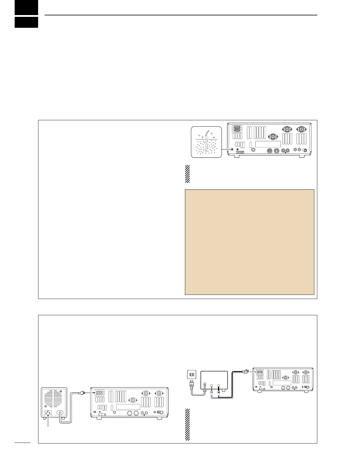
■Installation
1. Install a ground system for DC noise suppression
and RFI suppression
2. Install your DC power supply
3. Install lightning protection. This will help protect
more than your gear.
4. Install and connect an antenna system for the ap-
propriate bands of operation
5. Connect other peripheral equipment. This includes
microphones, headsets, TNC, amplifiers and any
other equipment necessary to make your shack
complete.
Although your radio will operate by connecting the DC
power supply and antenna, it is necessary to have a
good ground system in your shack. A ground connec-
tion is the electrical contact between the common
point of an electrical or electronic system and the
earth.
A good earth ground is necessary to prevent electrical
shock, eliminate problems from RFI and DC noise.
With more electronic devices being used today, it is
also important to reduce RFI and EMI. Although you
may not see interference in your shack, without a
grounding system, your neighbors may experience in-
terference. Even though many of these devices are
part 15, where they must accept interference from
their surrounding environment, it is best to eliminate
as much of the possible interference from your shack.
If you do not have a grounding system for your shack,
depending on the location of your shack, basement or
ground floor, a good ground system can be as simple
as a couple of ground rods driven 6 to 8 feet into the
soil. When installing your IC-746PRO to your ground-
ing system, the shortest most direct connection is rec-
ommended.
NOTE: There are many publications covering
proper grounding techniques. Check with your local
dealer for more information and recommendations.
DSome Symptoms if inadequate grounding
a. Poor DC Ground
60 Hz hum on the audio either Rx or Tx without the
antenna connected.
If you feel a tingling sensation when you touch a
metal surface. Surfaces such as the cover of your
radio or power supply.
b. Poor RF Ground
While transmitting and you feel a tingling sensation
when you touch a metal surface. Surfaces such as
the cover of your radio or power supply.
While transmitting, you experience interference to
other electronic devices, such as the telephone,
television or stereo audio systems.
The DC power supply is a device used to convert
110/220 V AC, also know as Household current, to a
steady source of 12 V DC.
The perfect match to your IC-746PRO is the PS-125.
This compact switching power supply is the matching
power supply for your IC-746PRO with a current rat-
ing of 25 A continuous duty. This plug and play unit;
plugs into the DC jack located on the rear of the radio.
•If you are not using the PS-125:
Connect the supplied DC power cable (OPC-025D) to
the appropriate color coded terminals, then insert the
DC connector into the DC jack located on the rear of
the radio.
NOTE: Although the power supply current require-
ment is quite low during receiving, this not the case
when you transmit. With many electrical devices in
the shack, it is very important to verify the electrical
circuit is not overloaded.
30 A fuses
AC cable
Transceiver
AC
outlet A DC power
supply*
*13.8 V; at least 23 A
Black
_
Red
+
to DC power
socket
Supplied
DC power cable
PS-125 DC power
socket Transceiver
DC power cable
Connect to an AC outlet using the supplied AC cable.
1. Grounding your Shack
2. Installing your DC Power Supply
II
QUICK REFERENCE GUIDE
3. Installing lightning protection
Although you may not live in an area with high occur-
rence for lightning storms, it is always wise to take
precautions for lightning or static discharges. Proper
lightning protection not only offers protection to the
ham gear, but the shack and most importantly the op-
erator.
NOTE: There are many publications covering
proper lightning protection, check with your local
dealer for more information and recommendations.
Whether your IC-746PRO is your first radio or one of
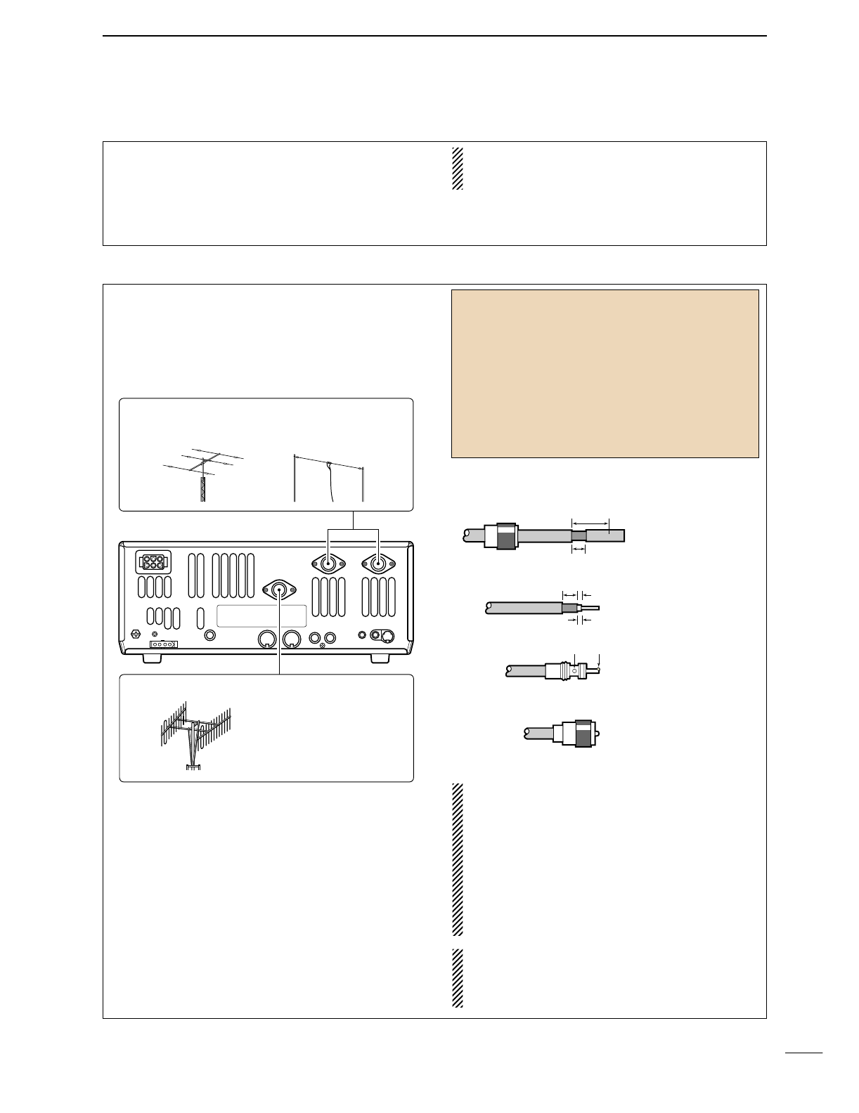
many, one of your key elements in a great shack is
the antenna system. There are three connections on
the back of your IC-746PRO, two for HF and 6 m and
one for 2 m. If you are using one antenna for HF and
6 m, for simplicity, connect the antenna coax to ANT1.
Your IC-746PRO is equipped with an internal antenna
tuner (ATU) for operation on 160–6 m. This ATU is de-
signed to work with an unbalanced 50 Ωfeedline. The
purpose of the internal antenna tuner is match the im-
pedance of your antenna system to as close to a
50 Ωload as possible. This ATU will not operate with
a long wire or ladder line (450 Ωor balanced feed-
lines). An external ATU such as the AH-4 would be
necessary for this kind of operation.
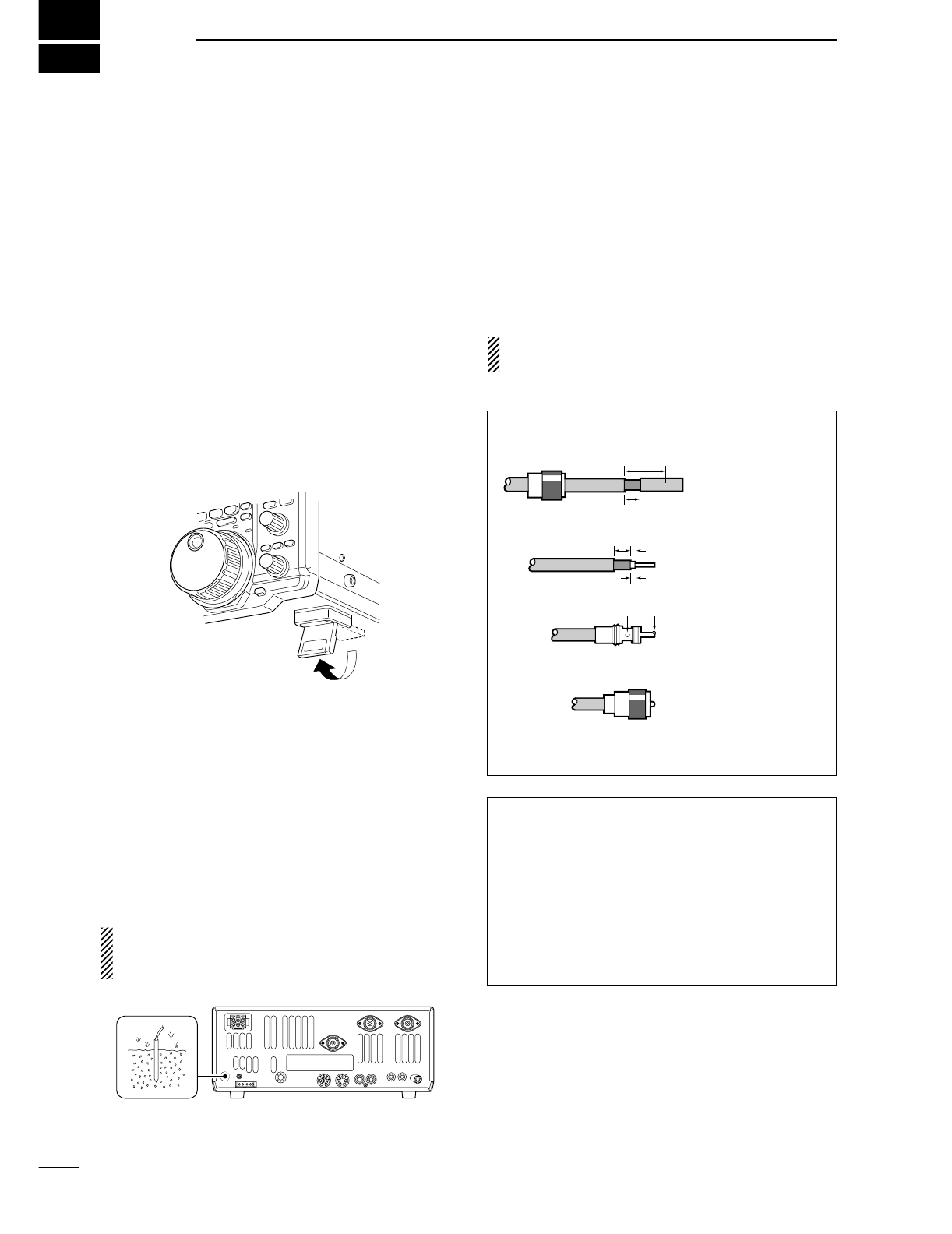
PL-259 CONNECTOR INSTALLATION EXAMPLE
30 mm ≈9⁄8in 10 mm ≈3⁄8in 1–2 mm ≈1⁄16 in
RWARNING: Although a mag mount antenna
works great on a vehicle, DO NOT use with IC-
746PRO on this type of antenna.
CAUTION: Although your IC-746PRO has protec-
tion to drop down power with a high SWR, this
does not completely protect the transceiver from
transmission without an antenna. Make sure you
have an antenna connect whenever you transmit
with your radio.
NOTE: There are many publications covering
proper antennas and their installation, check with
your local dealer for more information and recom-
mendations.
30 mm
10 mm (soft solder)
10 mm
1–2 mm
solder solder
Soft
solder
Coupling ring
Slide the coupling ring
down. Strip the cable
jacket and soft solder.
Slide the connector
body on and solder it.
Screw the coupling
ring onto the
connector body.
Strip the cable as
shown at left. Soft sol-
der the center con-
ductor.
q
w
e
r
Antenna SWR
Each antenna is tuned for a specified frequency
range and SWR may be increased out-of-range.
When the SWR is higher than approx. 2.0:1, the
transceiver’s power drops to protect the final tran-
sistor. In this case, an antenna tuner is useful to
match the transceiver and antenna. Low SWR al-
lows full power for transmitting even when using the
antenna tuner. The IC-746PRO has an SWR meter
to monitor the antenna SWR continuously.
ANTENNA 1, 2
[Example]: ANT1 for 1.8–18 MHz bands
ANT2 for 21–50 MHz bands
144 MHz ANTENNA
Connect a VHF (60–144 MHz)
antenna; impedance: 50 Ω.
4. Installing your antenna system

III
QUICK REFERENCE GUIDE
5. Connect other peripheral equipment
Everyone has his or her favorite ad-on gear; now is
the time to connect this gear! We will cover the basic
devices that can be connected to your IC-746PRO.
If you do not see the particular item you are wanting
to connect, refer to the Advance Connections section
starting on page 15.
Microphones: Connect it to the eight-pin connector on
the front of the radio.
MICROPHONES
HM-36 SM-20
■Operation
1. Voice
CW Key: There are several types of keys or keyers
that can be used with your IC-746PRO.
a. Lambic Key paddle: Use a 6.35(d) mm (1⁄4″)
stereo plug and connect to the [ELEC-KEY] jack lo-
cated on the front of the radio.
b. Straight Key: Use a 6.35(d) mm (1⁄4″) mono plug
and connect key to the back of the radio.
c. External Keyer: Use a 6.35(d) mm (1⁄4″) mono
plug and connect to the back of the radio.
d. Computer Keying: Use a 6.35(d) mm (1⁄4″) mono
plug and connect to the back of the radio.
NOTE: You will need to select the type of keyer you
are using in the Keyer Set mode. There are many
advanced CW functions in this set mode, until you
have a full understanding of these functions
change only the items necessary.
STRAIGHT KEY
(+)
(_)
CW KEY
A straight key can be used when the internal
electronic keyer is turned OFF in keyer set
mode. (p.34)
(dot)
(com)
(dash)
2. CW
IV
QUICK REFERENCE GUIDE
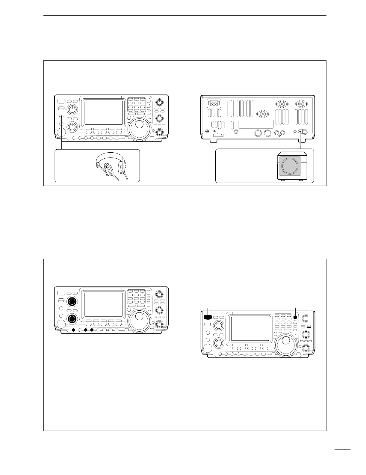
3. Other convenient items
Headphones:
A 6.35(d) mm (1⁄4″) mono jack for operation without
using the internal or external speakers. Perfect for op-
eration without disturbing others in the room.
External Speaker:
A 3.5(d) mm (1⁄8″) mono jack for operation with an ex-
ternal speaker. (Input impedance: 8 Ω/Max. input
power: 5 W)
EXTERNAL SPEAKER
SP-21 (optional)
HEADPHONES
1. Before powering up your radio, you may want to
make sure the following controls are set in the fol-
lowing positions:
•[AF] : Commonly referred to as the vol-
ume: fully CCW.
•[NR] : The noise reduction control: fully
CCW.
•[MIC GAIN] : The mic gain: fully CCW.
•[RF/SQL] : The control for the RF Gain and
Squelch circuits: 12 o’clock.
•[CW PITCH] : The control for the CW pitch:
12 o’clock.
•[KEY SPEED] : Internal CW Keyer Speed: fully
CCW
•[NOTCH] : Control for the manual notch:
12 o’clock
2. Resetting the CPU: Although you have purchased
a brand new radio, some settings may be changed
from the factory defaults from the CQ process. So
your radio can start from Factory Defaults resetting
the CPU is necessary.
[POWER] [F-INP] [M-CL]
■Your first contact
Now you should have your IC-746PRO installed in
your shack, and like a kid on his birthday, you are
probably excited to get on the air. We would like to
take you through a few basic operation steps to make
your first “On The Air” an enjoyable experience.
DTurning on the radio
V
QUICK REFERENCE GUIDE
DJust listening
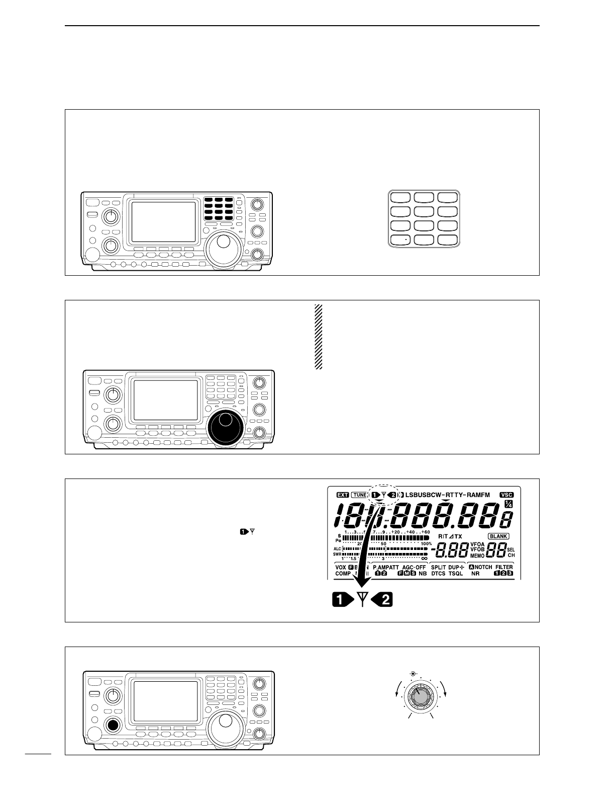
3. Verify proper antenna has been selected.
1. Select the desired band
Your IC-746PRO easy way of changing bands using
the keypad located just above the tuning knob on the
right hand side of the display. You will notice each
switch has two sets of numbers; one set of numbers
represents the band selection.
•Say you want to go to 20 meters or 14 MHz; you
would push the [14
5
]. This will immediately change
the displayed operating frequency to the 20-meter
band. This system is the triple band stacking regis-
ters. For more details on this system refer to p. 19.
GENE
50
0
21
7
24
8
28
9
14
5
10
4
18
6
3.5
2
1.8
1
7
3
144
ENT
Directly below the keypad is the tuning knob. This will
allow you to dial in the frequency you want to oper-
ate. You will notice the tuning speed [TS] is 10 Hz res-
olutions. Page 22 will instruct you on how to set the
tuning speed [TS] for 1 Hz resolution.
NOTE: Although you can directly enter the fre-
quency with the keypad, using the Band Stacking
Registers and the tuning knob is the most popular
method of hoping around the bands. For more in-
formation regarding the direct frequency entry
method, refer to p. 22.
You IC-746PRO has three antenna connectors. Two
for HF and 6m and a one for 2m. The selection for 2m
is automatic, where the HF and 6m is user selectable
for either one of the antenna jacks. For the first time
use, the antenna selector should show “” on the
display of your radio. Verify the antenna selected on
the display is the antenna port your connected your
antenna.
Either “1” or “2” appears.
*No indicator appear during
144 MHz operation.
Adjust this control to a comfortable audio level.
AF RF/SQL
No audio output Max. audio output
Decreases Increases
2. Tune to the desired frequency
4. Adjust audio output
VI
QUICK REFERENCE GUIDE
DWhat are you hearing?
Stop and focus on what you are hearing. Do you hear
a lot of noise? Is the signal intelligible? Are you set up
for the right mode? How about the filters?
1. Verify mode
Your IC-746PRO has many features to reduce QRM
and QRN from the desired signal.
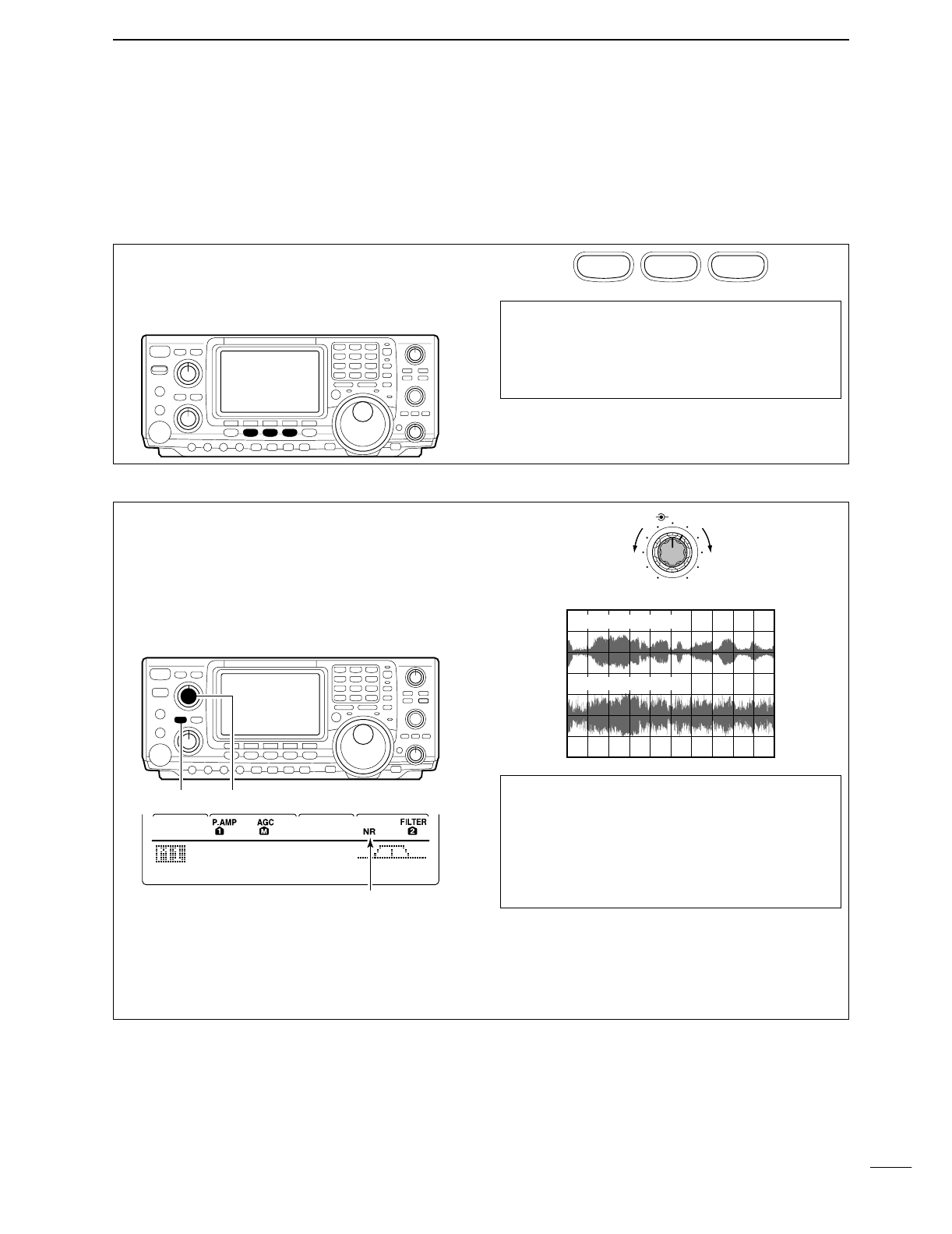
a. Noise Reduction: The noise reduction system on
your IC-746PRO is part of the 32-bit DSP. This is
used to reduce the hiss and QRM levels. To acti-
vate, push the [NR] switch located just to the right
of the [PHONES] jack.
b. Adjusting the Noise Reduction: The noise re-
duction is completely variable on how much of the
DSP Noise Reduction is used. Located just above
the [NR] switch, this is where the [NR] level con-
trol.
Hint!
How much [NR] will depend on the S/N ratio, Signal
to Noise. Just using the [NR] may cause the signal
to become distorted. To keep this from happening,
using the [NR] along with the [RF GAIN] and Filter
bandwidths will allow you to zero in on the desired
signal with as little QRM as possible.
Noise reduction ON
Noise reduction OFF
NR NOTCH
OFF
Decreases Increases
AGC
DUP
CMP
TBW
SCP
[NR] [NR]
Appears
Although your IC-746PRO will automatically select
USB or LSB in the HF bands, it will not select any of
the other modes. You will need to select the proper
mode whether CW, RTTY, AM or FM.
Hint!
The Triple Band Stacking Registers will memorize
the last three frequencies used in the band, as well
as the Mode, Filter, Tuner and AGC settings. Mak-
ing band hoping much easier.
SSB
CW/RTTY
AM/FM
2. Reducing interference
VII
QUICK REFERENCE GUIDE
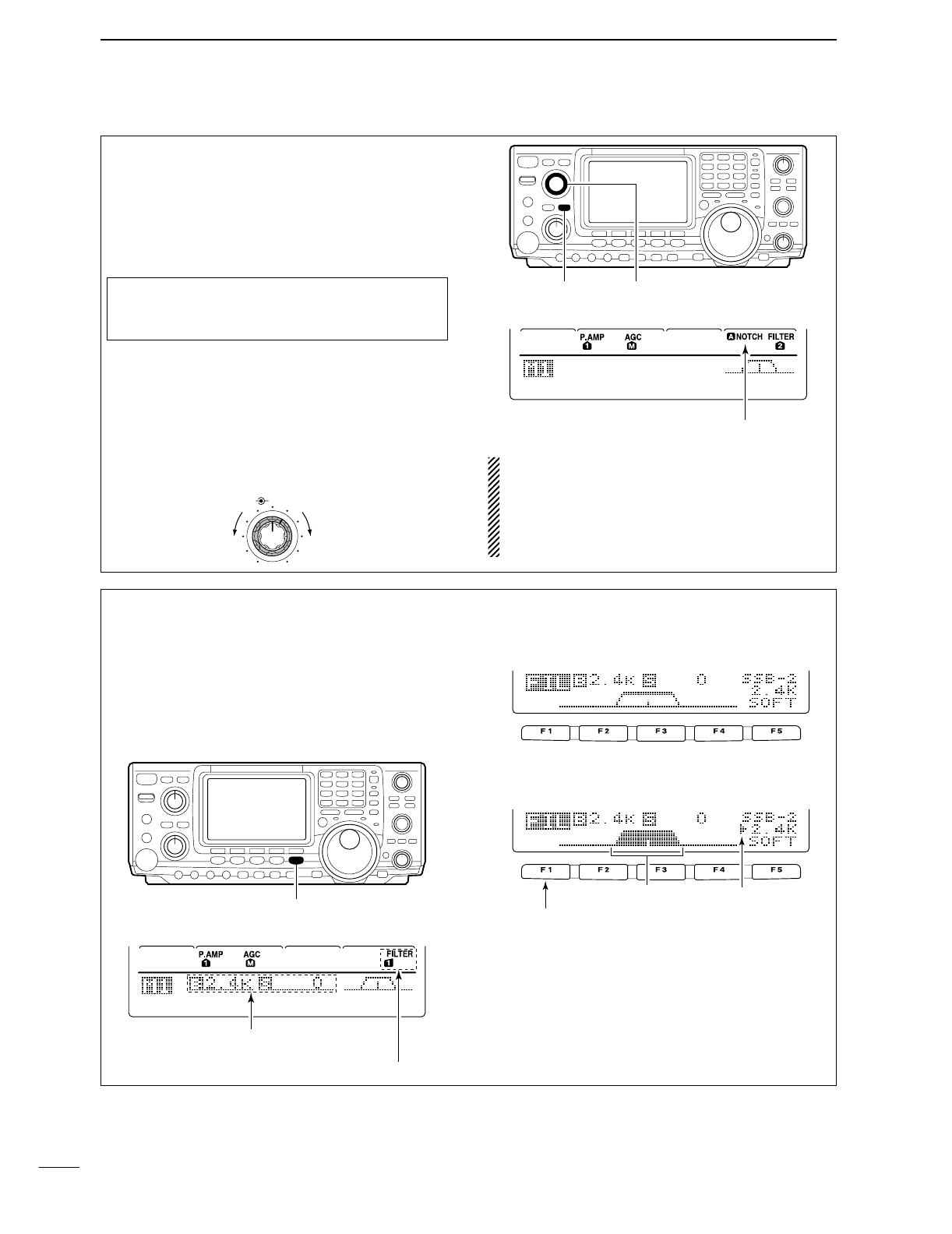
c. Notch: There are two notch systems on your IC-
746PRO.
•
Automatic:
The automatic notch will track up to three
heterodynes. This is great for eliminating hetero-
dynes on 80 and 160 meters, and those annoying
tune up signals across the band. Once selected an
icon will appear “ANOTCH” on the display.
•
Manual:
The Manual notch provides 70 dB of atten-
uation to pin point an interfering signal. The 12 o’-
clock position is on the operating frequency, turning
the Notch knob clockwise moves the notch up the
band and counter clockwise will move the notch
down the band. Once selected an icon will appear
“NOTCH” on the display. NOTE: Your IC-746PRO is equipped with multiple
AGC circuits. This allows the DSP to filter out inter-
fering signals and QRM, while also taking this in-
terference out of the AGC. Bottom line, this will ei-
ther eliminate or greatly reduce the pumping of the
AGC from the interfering signal.
AGC
DUP
CMP
TBW
SCP
[A/NOTCH] [NOTCH]
Notch function indicators
NR NOTCH
Low freuency High frequency
Hint!
The Automatic Notch will not operated in the SSB
data, CW or RTTY modes.
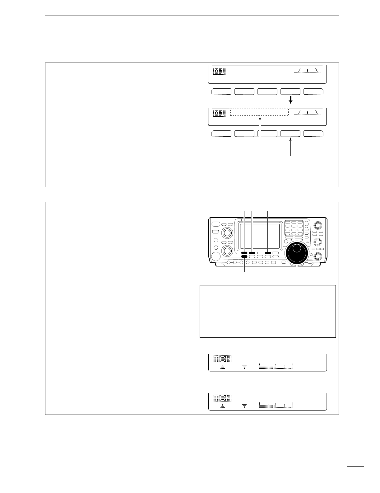
d. Filters: Your IC-746PRO has an incredible IF DSP
based filter network with over 100 settings.
•Dial in your filters: By pushing [FILTER] for 1 sec.,
you enter the filter set mode. This is where you are
able set the three filter presets. Across the bottom of
the display you will see the “BW” icon. The switch di-
rectly below, along with the tuning dial, will be used
to select the changes you will make.
BW
• Filter set mode indication
Shows the selected filter and passband width.
BW
• Indication while setting
While pushing [F1 BW], rotate the tuning dial to set
passband width.
Reverses Appears
AGC
DUP
CMP
TBW
SCP
[FILTER]
The selected filter width is indicated
for approx. 1 sec. when [FILTER] is
pushed. Filter selection
VIII
QUICK REFERENCE GUIDE
d. Filters:— continued
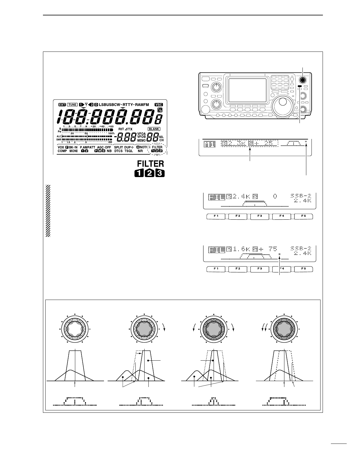
•
On the fly adjustment: Once the adjustments have
been made in the filter set mode, you can make on
the fly changes by using the Twin Pass Band Tuning,
Twin PBT. You will be able to see the effects of the
Twin PBT on the upper left hand side of the screen.
NOTE: The Twin PBT filters shift the two IF DSP
filters (See Diagrams below and right). This feature
allows both an IF shift as well as a narrowing of the
Pass Band. Although you can narrow the pass
band by shifting the two filters, this does not nar-
row both filters, thus the filter shape is not nar-
rowed. You may hear some signal artifacts pass
through this filter adjustment.
PBT operation example
BW
• Filter set mode indication
Shows the selected filter and passband width.
BW
• Indication while PBT setting
Appears when passband is shifted.
*Pushing [PBTC] for 1 sec., the shifted value
return to default setting and the “dot” disappears.
AGC
DUP
CMP
TBW
SCP
Passband width and shifting value are
indicated while [TWIN PBT] is operated.
[TWIN PBT] control
[PBTC]
Appears when PBT is used.
One of “1,” “2” or “3” is
displayed for selected filter
number indications.
interference
inteference
interference desired signal
desired signal
pass band
IF center frequency
Center Passband Passband
IF center freq.
IF shift
IX
QUICK REFERENCE GUIDE
Once you have mastered your filter settings, one last
feature to enable the most intelligible audio is the ac-
tual audio tone you hear. You can adjust the equal-
ization of your received audio ±5dB.
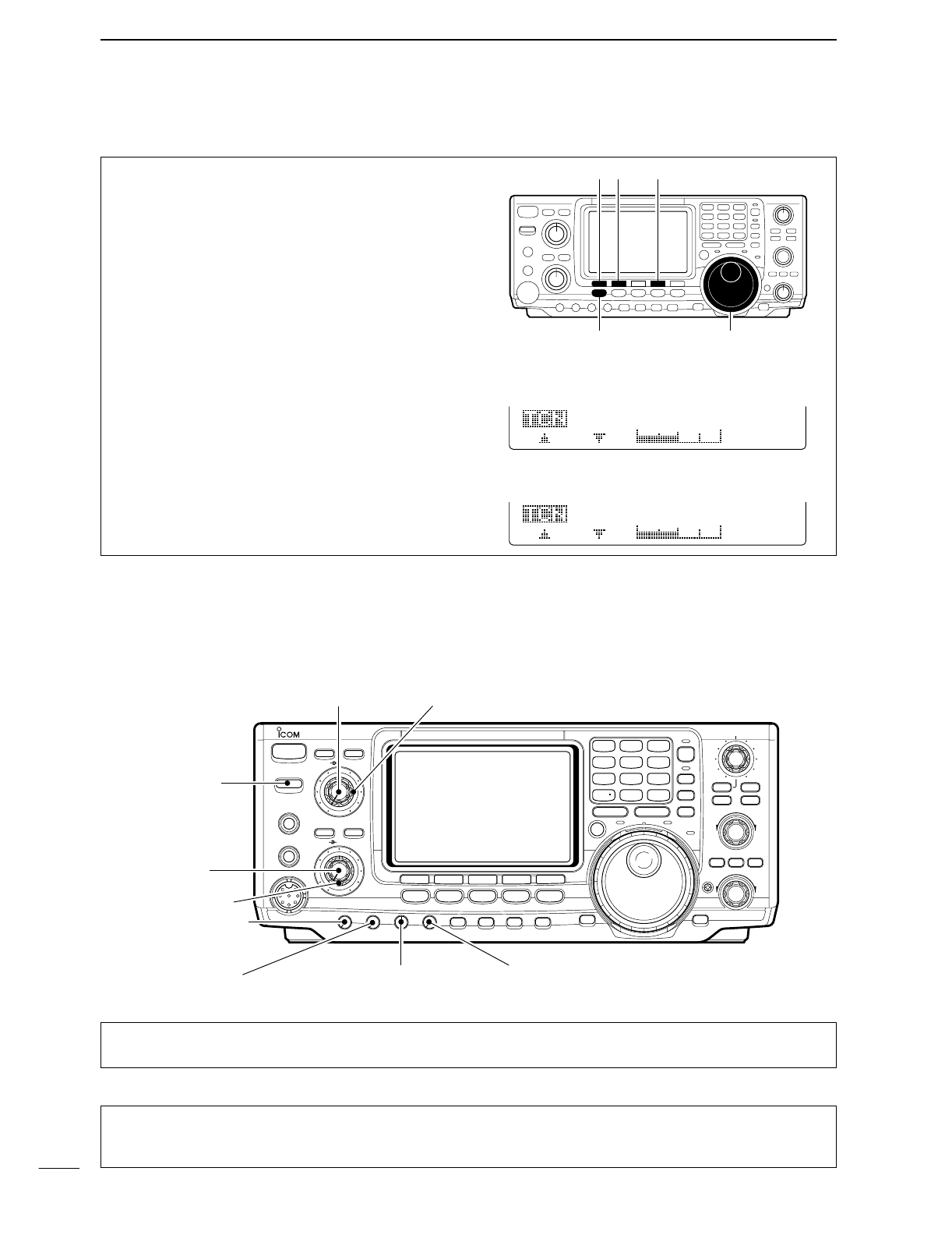
qPush [MENU] several time, or until M2 is shown on
the display.
wPush [F4 TCN] for the Tone Control set mode.
ePush the appropriate mode switch to adjust SSB,
AM or FM.
rPush [F1 ≤] or [F2 ≥] to change to the desired
component.
[F1 ≤]
Tuning dial[MENU]
[F2 ≥] [F4 TCN]
3. RX Tone Control:
1. RX Bass
This item adjusts the bass level of the receive audio
tone from –5 dB to +5 dB in 1 dB steps.
RX
Bass
SSB
O
3
2. RX Treble
This item adjusts the treble level of the receive audio
tone from –5 dB to +5 dB in 1 dB steps.
RX
Treble
SSB
O
4
We hope these pointers have been helpful. Now you
are ready for the “Ready to call CQ?”.
■Ready to call CQ?
The 32-bit DSP in your IC-746PRO is capable of giving
you the type of transmit audio for your SSB Operation.
POWER
TRANSMIT
PHONES
ELEC-KEY
MIC
NR
A/NOTCH
TUNER
ANT
HF/VHF TRANSCEIVER
NR
NOTCH
AF
MIC GAIN
RF PWR
CW PITCH
F 1
F
2F
3
F
4
F
5
XFC
MP-W
GENE
50
0
21
7
24
8
28
9
14
5
10
4
18
6
3.5
2
1.8
1
7
3
144
ENT
MP-R
TX RX LOCK
TWIN PBT
M-CH
RIT
CLEAR
∂TX
RIT/∂TX
TS
SPLIT
PBTC
F-INP
A/B
V/M
MW
M-CL
KEY SPEED
P.AMP/ATT
NB
VOX/BK-IN
MONITOR
CALL
LOCK/
SPCH
RF/SQL
i746PRO
MENU SSB
CW/RTTY
AM/FM
FILTER
[NR]: Max. CCW [NOTCH]: Max. CCW
[AF]: Max. CCW
[TRANSMIT]: OFF
[MIC GAIN]: Max. CCW
[RF PWR]: Max. CCW [CW PITCH]: 12 o’clock
[RF/SQL]: 12 o’clock
[KEY SPEED]: Max. CCW
1. Setting up your transmit audio
2. Mic Gain
The microphone gain is used for proper transmit
audio level for full output power. Although the hand
microphone supplied with your IC-746PRO should re-
quire a setting of the [MIC GAIN] you should find a
10–11 o’clock position.
X
QUICK REFERENCE GUIDE
Verify you have selected a clear frequency
and call out your CQ!
The capable of changing the pass band of your trans-
mit audio, is at your finger tip. Regardless of the con-
dition of the speech compressor, you can adjust by
selecting the [F4 TBW].
You will find this located on the M1 menu. Pushing the
[F4 TBW] for 1 sec. you can step through the TX
audio band pass.
There are three levels of audio passband available
(Wide, Mid, and Nar).
TX Audio Passband widths
Wide :2.9 kHz ; Great Full Audio
Mid :2.6 kHz ; Great for operators with
deep full voices
Nar :2.0 kHz ; Great for breaking through
pile ups
F 1
F
2F
3
F
4
F
5
F 1 F 2 F 3 F 4 F 5
AGC
DUP
CMP
TBW
SCP
AGC
DUP
CMP
TBW
SCP
TX
BW=WIDE
Push [F4]
Push [F4] for 1 sec. to select the transmit filter width.
The selected transmit filter width
is displayed for approx. 1 sec.
3. DSP TX Audio Pass Band
4. Microphone Equalizer
Although these bandwidths are fixed, the Microphone
Tone Control will give you more audio control for your
Voice operation on SSB, AM, and FM modes. Your
IC-746PRO is equipped with a very powerful equal-
izer system with 121 possible combinations. This is
achieved by using the separate bass and treble ad-
justments. The default for both the Base and Treble
is at 0 dB.
Entering Microphone Tone Control set mode:
qPush [MENU] several time, or until M2 is shown on
the display.
wPush [F4 TCN] for the Tone Control set mode.
ePush the appropriate mode switch to adjust SSB,
AM, or FM.
rPush [F1 ≤] or [F2 ≥] to change to the desired
component.
Hint!
Voice patterns and audio characteristics vary with
each operator, therefore the [MIC GAIN], DSP TX
Audio Pass Band and Microphone Tone Control
settings will be different for each operator. Actual on
air experimenting is necessary to get the just right
sound.
[F1 ≤]
Tuning dial[MENU]
[F2 ≥] [F4 TCN]
1. TX Bass
This item adjusts the bass level of the transmit audio
tone from –5 dB to +5 dB in 1 dB steps.
TX
Bass
SSB
O
1
2. TX Treble
This item adjusts the treble level of the transmit audio
tone from –5 dB to +5 dB in 1 dB steps.
TX
Treble
SSB
O
2
1
1
PANEL DESCRIPTION
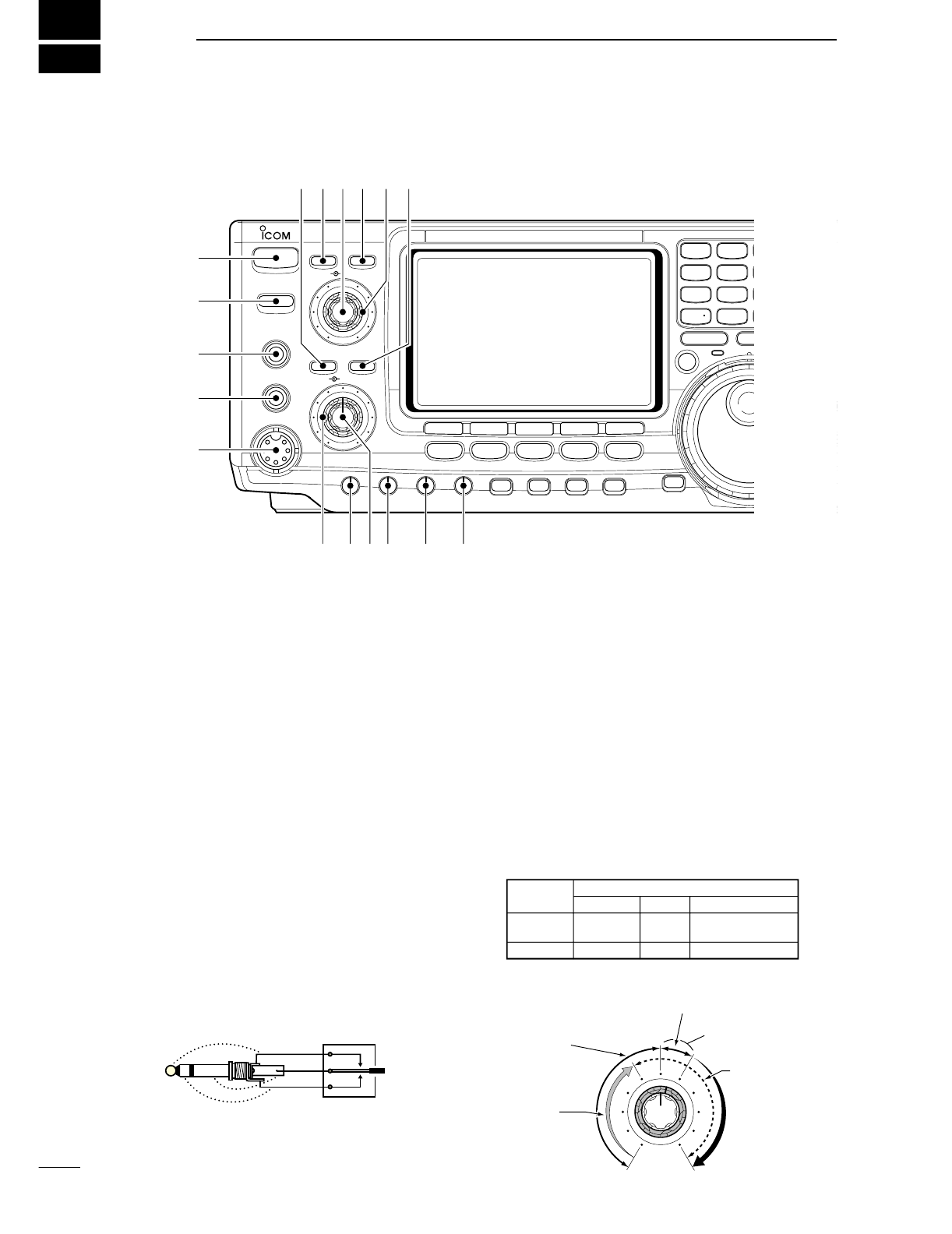
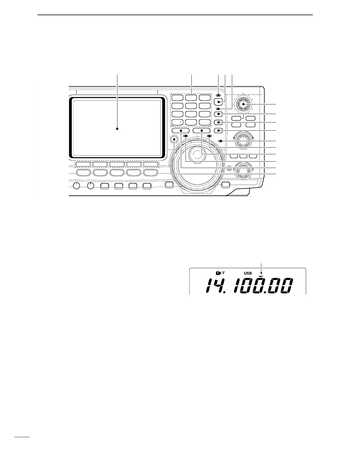
■Front panel
qPOWER SWITCH [POWER]
➥Push momentarily to turn power ON.
•Turn the optional DC power supply ON in advance.
➥Push for 1 sec. to turn power OFF.
wTRANSMIT SWITCH [TRANSMIT]
Selects transmitting or receiving.
•The [TX] indicator lights red while transmitting and the
[RX] indicator lights green when the squelch is open.
eHEADPHONE JACK [PHONES]
Accepts headphones.
•Output power: 5 mW with an 8 Ωload.
•When headphones are connected, the internal speaker
or connected external speaker does not function.
rELECTRONIC KEYER JACK [ELEC-KEY] (p. 14)
Accepts a paddle to activate the internal electronic
keyer for CW operation.
•Selection between the internal electronic keyer, bug-key
and straight key operation can be made in keyer set
mode. (p. 34)
•A straight key jack is separately available on the rear
panel. See [KEY] on p. 7.
•Keyer polarity (dot and dash) can be reversed in keyer
set mode. (p. 34)
•4-channel memory keyer is available for your conve-
nience. (p. 30)
tMICROPHONE CONNECTOR [MIC]
Accepts the supplied or optional microphone.
•See p. 100 for appropriate microphones.
•See p. 12 for microphone connector information.
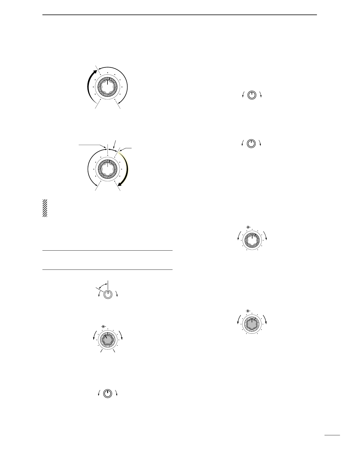
yRF GAIN CONTROL/SQUELCH CONTROL
[RF/SQL] (outer control)
Adjusts the RF gain and squelch threshold level.
The squelch removes noise output from the speaker
(closed condition) when no signal is received.
•The squelch is particularly effective for FM. It is also
available for other modes.
•12 to 1 o’clock position is recommended for any setting
of the [RF/SQL] control.
•The control can be set as ‘Auto’(RF gain control in SSB,
CW and RTTY; squelch control in AM and FM) or
squelch control (RF gain is fixed at maximum) in set
mode as follows. (p. 81)
•When setting as RF gain/squelch control
Recommended level
RF gain
adjustable
range
Maximum
RF gain
S-meter
squelch
Noise squelch (FM mode)
Squelch is
open.
MODE
SSB, CW
RTTY
AM, FM
AUTO
RF GAIN
SQL
SQL
SET MODE SETTING
SQL
SQL
RF GAIN + SQL
RF GAIN + SQL
RF GAIN + SQL
(dot)
(com)
(dash)
POWER
TRANSMIT
PHONES
ELEC-KEY
MIC
NR
A/NOTCH
TUNER
ANT
HF/VHF TRANSCEIVER
NR
NOTCH
AF
MIC GAIN
RF PWR
CW PITCH
F 1
F
2F
3
F
4
F
5
XFC
MP-W
GENE
50
0
21
7
24
8
28
9
14
5
10
4
18
6
3.5
2
1.8
1
7
3
144
ENT
MP-R
TX RX LOCK
TS
SPLIT
F-INP
A/B
KEY SPEED
P.AMP/ATT
NB
VOX/BK-IN
MONITOR
CALL
LOCK/
SPCH
RF/SQL
i746PRO
MENU SSB
CW/RTTY
AM/FM
FILTER
q
w
e
r
t
yuio !0 !1
!4!5!6!7 !3 !2
2
1
PANEL DESCRIPTION
•When functioning as RF gain control
(Squelch is fixed open; SSB, CW, RTTY only)
•When functioning as squelch control
(RF gain is fixed at maximum.)
While rotating the RF gain control, noise may be
heard. This comes from the DSP unit and does not
indicate an equipment malfunction.
uMIC GAIN CONTROL [MIC GAIN]
Adjusts microphone input gain.
•The transmit audio tone in SSB, AM and FM modes can
be adjusted in tone control set mode. (p. 88)
✔How to set the microphone gain.
Set the [MIC] control so that the ALC meter sometimes
swings during normal voice transmission in SSB mode.
iAF CONTROL [AF] (inner control)
Varies the audio output level from the speaker.
oRF POWER CONTROL [RF PWR]
Continuously varies the RF output power from min-
imum (less than 5 W*) to maximum (100 W*).
*AM mode: less than 5 W to 40 W
!0 CW PITCH CONTROL [CW PITCH] (p. 28)
Shifts the received CW audio pitch and monitored
CW audio pitch without changing the operating fre-
quency.
•The pitch can be changed from 300 to 900 Hz in approx.
25 Hz steps.
!1 ELECTRONIC CW KEYER SPEED CONTROL
[KEY SPEED] (p. 28)
Adjusts the internal electronic CW keyer’s speed.
•6 wpm (min.) to 60 wpm (max.) can be set.
!2 AUTO NOTCH/MANUAL NOTCH SWITCH
[A/NOTCH] (p. 53)
Toggles the notch function between manual and au-
tomatic when pushed.
•“NOTCH” appears when manual; “ANOTCH” appears
when automatic notch is selected.
!3 NOTCH CONTROL [NOTCH] (outer control; p. 53)
Adjusts the notch filter frequency to remove a inter-
ference signal.
!4 ANTENNA SELECTOR SWITCH [ANT] (p. 75)
Switches the antenna connector selection between
ANT1 and ANT2 when pushed.
!5 NOISE REDUCTION LEVEL CONTROL [NR]
(inner control; p. 53)
Adjusts the noise reduction level when the noise re-
duction is in use. Set for maximum readability.
!6 ANTENNA TUNER SWITCH [TUNER] (pgs. 76,
77)
➥Turns the antenna tuner ON and OFF (bypass)
when pushed momentarily.
➥Starts to tune the antenna manually when
pushed for 1 sec.
•When the tuner cannot tune the antenna, the tuning
circuit is bypassed automatically after 20 sec.
!7 NOISE REDUCTION SWITCH [NR] (p. 53)
Switches the noise reduction ON and OFF.
•“NR” appears while the noise reduction is activated.
NR NOTCH
OFF
Decreases Increases
NR NOTCH
Low freuency High frequency
Slow Fast
KEY SPEED
CW PITCH
IncreasesDecreases
RF PWR
IncreasesDecreases
AF RF/SQL
No audio output Max. audio output
Decreases Increases
MIC GAIN
Recommended level for
an Icom microphone
IncreasesDecreases
Squelch is
open.
S-meter
squelch
S-meter squelch
threshold
Noise squelch
threshold
(FM mode)
Shallow Deep
Noise squelch (FM mode)
Minimum RF gain
Adjustable
range
Maximum
RF gain
3
1PANEL DESCRIPTION
■Front panel (continued)
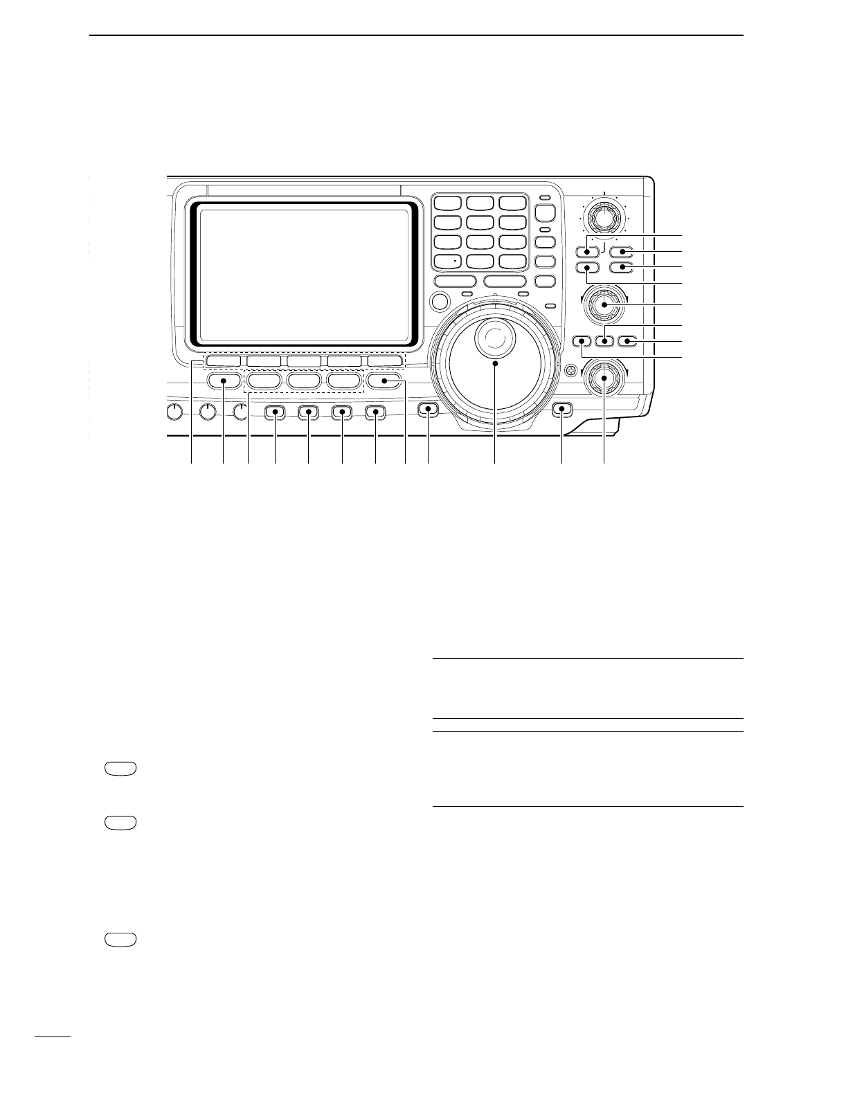
!8 MULTI-FUNCTION SWITCHES [F1]–[F5]
➥Push to select the function indicated in the LCD
display above these switches. (p. 11)
•Functions vary depending on the operating condition.
➥Push to input a character for memory keyer pro-
gramming or memory name. (pgs. 31, 66)
!9 MENU SWITCH [MENU]
Push to change the set of functions assigned to the
multi-function switches.
•Toggles between menu 1 (M1) and menu 2 (M2).
@0 MODE SWITCHES
Selects the desired mode. (p. 23)
•Announces the selected mode when an optional UT-102
is installed. (p. 89)
➥Selects USB and LSB mode alternately.
➥Selects SSB data mode (USB-D, LSB-D)
when pushed for 1 sec. in SSB mode.
➥Selects CW and RTTY mode alternately.
➥Switches CW and CW-R (CW reverse)
mode when pushed for 1 sec. in CW
mode.
➥Switches RTTY and RTTY-R (RTTY re-
verse) mode when pushed for 1 sec. in
RTTY mode.
➥Selects AM and FM mode alternately.
➥Selects AM/FM data mode (AM-D, FM-D)
when pushed for 1 sec. AM/FM mode.
@1 PREAMP/ATTENUATOR SWITCH [P.AMP/ATT]
(p. 48)
➥Push momentarily to toggle between preamp-1
and preamp-2.
•“P.AMP1” activates for HF all bands.
•“P.AMP2” activates high-gain preamp for 24 MHz
band and above.
➥Push for 1 sec. to toggle the attenuator function
ON and OFF.
✔What is the preamp?
The preamp amplifies received signals in the front end cir-
cuit to improve the S/N ratio and sensitivity. Select “P.AMP1”
or “P.AMP2” when receiving weak signals.
✔What is the attenuator?
The attenuator prevents a desired signal from distorting
when very strong signals are near the desired frequency, or
when very strong electric fields, such as from a broadcast-
ing station, are near your location.
@2 NOISE BLANKER SWITCH [NB] (p. 51)
➥Switches the noise blanker ON and OFF when
pushed. The noise blanker reduces pulse-type
noise such as that generated by automobile igni-
tion systems. This function cannot be used for
FM, or non-pulse-type noise.
•“NB” appears while the noise blanker is activated.
➥Enters the noise blanker level set mode when
pushed for 1 sec.
AM/FM
CW/RTTY
SSB
T
Y
NR
A/NOTCH
TUNER
ANT
HF/VHF TRANSCEIVER
NR
NOTCH
AF
MIC GAIN
RF PWR
CW PITCH
F 1
F
2F
3
F
4
F
5
XFC
MP-W
GENE
50
0
21
7
24
8
28
9
14
5
10
4
18
6
3.5
2
1.8
1
7
3
144
ENT
MP-R
TX RX LOCK
TWIN PBT
M-CH
RIT
CLEAR
∂TX
RIT/∂TX
TS
SPLIT
PBTC
F-INP
A/B
V/M
MW
M-CL
KEY SPEED
P.AMP/ATT
NB
VOX/BK-IN
MONITOR
CALL
LOCK/
SPCH
RF/SQL
i746PRO
MENU SSB
CW/RTTY
AM/FM
FILTER
#7
#6
#5
#4
#3
#2
#1
#0
!9 @0 @1!8 @2 @3 @4 @6@5 @7 @8 @9

4
1
PANEL DESCRIPTION
@3 VOX/BREAK-IN SWITCH [VOX/BK-IN]
➥In SSB, AM and FM modes, push momentarily to
turn the VOX function ON and OFF (p. 54); push
for 1 sec. to enter VOX set mode (p. 54).
➥In CW mode, push momentarily to turn the semi
break-in, full break-in or break-in OFF (p. 56);
push for 1 sec. to enter break-in set mode (p. 56).
✔What is the VOX function?
The VOX function (voice operated transmission) starts trans-
mission without pushing the transmit switch or PTT switch
when you speak into the microphone; then, automatically re-
turns to receive when you stop speaking.
✔What is the break-in function?
The break-in function switches transmit and receive with CW
keying. Full break-in (QSK) can monitor the receive signal
during keying.
@4 MONITOR SWITCH [MONITOR] (p. 57)
➥Monitors your transmitted signal.
➥Enters to monitor set mode when pushed for
1 sec.
@5 FILTER SWITCH [FILTER] (p. 50)
➥Selects one of 3 IF filter settings.
➥Enters the filter set mode when pushed for 1 sec.
@6 CALL SWITCH [CALL] (p. 64)
Selects the call channel when pushed momentarily.
@7 TUNING DIAL (p. 21)
Changes the displayed frequency, selects set mode
items, etc.
@8
LOCK/SPEECH SWITCH [LOCK/SPCH]
➥Push momentarily to toggle the dial lock function
ON and OFF. (p. 53)
➥Pushing for 1 sec. announces the selected read-
out frequency and S-meter indication when an
optional UT-102 is installed. (p. 89)
@9 RIT/∂TX CONTROL [RIT/∂TX] (pgs. 48, 56)
Shifts the receive and/or transmit frequency without
changing the transmit and/or receive frequency
while the RIT and/or ∂TX functions are ON.
•Rotate the control clockwise to increase the frequency,
or rotate the control counterclockwise to decrease the
frequency.
•The shift frequency range is ±9.99 kHz in 10 Hz steps
(or ±9.999 kHz in 1 Hz steps).
#0 RIT SWITCH [RIT] (p. 48)
➥
Turns the RIT function ON and OFF when pushed.
•Use the [RIT/∂TX] control to vary the RIT frequency.
➥Adds the RIT shift frequency to the operating fre-
quency when pushed for 1 sec.
✔What is the RIT function?
The RIT (Receiver Incremental Tuning) shifts the receive fre-
quency without shifting the transmit frequency.
This is useful for fine tuning stations calling you on an off-fre-
quency or when you prefer to listen to slightly different-
sounding voice characteristics, etc.
#1 CLEAR SWITCH [CLEAR] (pgs. 48, 56)
Clears the RIT/∂TX shift frequency when pushed
for 1 sec.
#2 ∂TX SWITCH [∂TX] (p. 57)
➥Turns the ∂TX function ON and OFF when
pushed.
•Use the [RIT/∂TX] control to vary the ∂TX frequency.
➥Adds the ∂TX shift frequency to the operating
frequency when pushed for 1 sec.
✔What is the ∂TX function?
The ∂TX shifts the transmit frequency without shifting the re-
ceive frequency. This is useful for simple split frequency op-
eration in CW, etc.
#3 MEMORY CHANNEL SELECTOR [M-CH] (p. 62)
Select a memory channel.
•Rotate clockwise to increase the memory channel; ro-
tate counterclockwise to decrease the memory channel.
#4 VFO/MEMORY SWITCH [VFO/MEMO]
➥Switches the selected readout operating mode
between the VFO mode and memory mode when
pushed. (pgs. 20, 61)
➥Transfers the memory contents to VFO when
pushed for 1 sec. (p. 65)
#5 MEMORY CLEAR SWITCH [M-CL] (p. 62)
Clears the selected readout memory channel con-
tents when pushed for 1 sec. in memory mode.
•The channel becomes a blank channel.
•This switch does not function in VFO mode.
#6 MEMORY WRITE SWITCH [MW] (p. 63)
Stores the selected readout frequency and operat-
ing mode into the displayed memory channel when
pushed for 1 sec.
•This function is available both in VFO and memory
modes.
#7 PBT CLEAR SWITCH [PBTC] (p. 52)
Clears the PBT settings when pushed for 1 sec.
Low shift High shift
RIT/∂TX
■Front panel (continued)
#8 TRANSMIT FREQUENCY CHECK SWITCH [XFC]
(pgs. 45, 48)
Monitors the transmit frequency when pushed and
held.
•While pushing this switch, the transmit frequency can be
changed with the tuning dial, keypad or memo pad.
•When the split lock function is turned ON, pushing [XFC]
cancels the dial lock function. (p. 60)
#9 MEMO PAD-WRITE SWITCH [MP-W] (p. 67)
Programs the selected readout frequency and op-
erating mode into a memo pad.
•The 5 most recent entries remain in memo pads.
•The transmit frequency is programmed when pushed to-
gether with [XFC].
•The memo pad capacity can be expanded from 5 to 10
in set mode for your convenience. (p. 84)
$0 TRANSMIT INDICATOR [TX]
Lights red while transmitting.
$1 MEMO PAD-READ SWITCH [MP-R] (p. 67)
Each push calls up a frequency and operating
mode in a memo pad. The 5 (or 10) most recently
programmed frequencies and operating modes can
be recalled, starting from the most recent.
•The memo pad capacity can be expanded from 5 to 10
in set mode for your convenience. (p. 84)
$2 RECEIVE INDICATOR [RX]
Lights green while receiving a signal and when the
squelch is open.
$3 LOCK INDICATOR [LOCK] (p. 53)
Lights when the dial lock function is activated.
$4 QUICK TUNING SWITCH [TS] (p. 21)
➥Turns the quick tuning step ON and OFF.
•While the quick tuning indicator is displayed, the fre-
quency can be changed in programmed kHz steps.
•0.1, 1, 5, 9, 10, 12.5, 20 and 25 kHz quick tuning
steps are available.
➥While the quick tuning step is OFF, turns the 1 Hz
step ON and OFF when pushed for 1 sec.
•1 Hz indication appears in and the frequency can be
changed in 1 Hz steps.
➥While the quick tuning step is ON, enters the
quick tuning step set mode when pushed for
1 sec.
$5 VFO SELECT SWITCH [A/B] (p. 20)
➥Push to toggle between VFO A and VFO B.
➥Push for 1 sec. to equalize the frequency and op-
erating mode of the two VFO’s.
Quick tuning indicator
5
1PANEL DESCRIPTION
NR
A/NOTCH
NER
ANT
HF/VHF TRANSCEIVER
NR
NOTCH
AF
MIC GAIN
RF PWR
CW PITCH
F 1
F
2F
3
F
4
F
5
XFC
MP-W
GENE
50
0
21
7
24
8
28
9
14
5
10
4
18
6
3.5
2
1.8
1
7
3
144
ENT
MP-R
TX RX LOCK
TWIN PBT
M-CH
RIT
CLEAR
∂TX
RIT/∂TX
TS
SPLIT
PBTC
F-INP
A/B
V/M
MW
M-CL
KEY SPEED
P.AMP/ATT
NB
VOX/BK-IN
MONITOR
CALL
LOCK/
SPCH
RF/SQL
i746PRO
MENU SSB
CW/RTTY
AM/FM
FILTER
$7
$4
$5
$6
$3
$2
$1
$0
#9
#8
%2 %0 $9 $8%1
6
1
PANEL DESCRIPTION
$6 SPLIT SWITCH [SPLIT]
➥Turns the split function ON and OFF when
pushed.(p. 59)
➥Turns the quick split function ON, when pushed
for 1 sec. (p. 60)
•The offset frequency is shifted from the displayed fre-
quency.
•The quick split function can be turned OFF using set
mode. (p. 82)
➥Turns the split function ON and sets the transmit
frequency after inputting an offset frequency with
the keypad (±4 MHz in 1 kHz steps; p. 59).
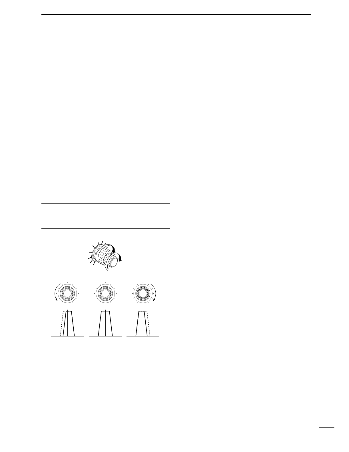
$7 PASSBAND TUNING CONTROLS [TWIN PBT]
Adjust the receiver’s “passband width” of the DSP
filter. (p. 52)
•Passband width and shift frequency are displayed in the
multi-function switch indicator.
•Push [PBTC] for 1 sec. to clear the settings when not in
use.
•Variable range is set to half of the IF filter passband
width. 25 Hz steps and 50 Hz steps are available.
•These controls function as an IF shift control while in AM
mode and when the RTTY filter is turned ON. Only the
inner control may function in this case.
✔What is the PBT control?
General PBT function electronically narrows the IF passband
width to reject interference. This transceiver uses the DSP
circuit for the PBT function.
$8 SPLIT INDICATOR (p. 59)
Lights during split operation.
$9 FREQUENCY INPUT SWITCH [F-INP] (p. 22)
Push to toggle keypad input between frequency and
band.
•The frequency input indicator lights during fre-
quency input is selected for the keypad.
%0 FREQUENCY INPUT INDICATOR (p. 22)
Lights during frequency input from the keypad is
enable.
%1 KEYPAD
➥Pushing a key selects the operating band.
•[GENE] selects the general coverage band.
➥Pushing the same key 2 or 3 times calls up other
stacked frequencies in the band. (p. 19)
•Icom’s triple band stacking register memorizes 3 fre-
quencies in each band.
➥After pushing [F-INP], enters a keyed frequency.
Pushing [144 ENT] is necessary at the end.
(p. 22)
•e.g. to enter 14.195 MHz, push [F-INP] [1] [4] [•] [1]
[9] [5] [144 ENT].
%2 LCD FUNCTION DISPLAY
(See pgs. 9, 10 for details.)
Shows the operating frequency, function switch
menus, band scope screen, memory name screen,
set mode settings, etc.
PBT1
PBT2
TWIN PBT
Low cut High cutCenter
TWIN PBT TWIN PBT TWIN PBT
–+
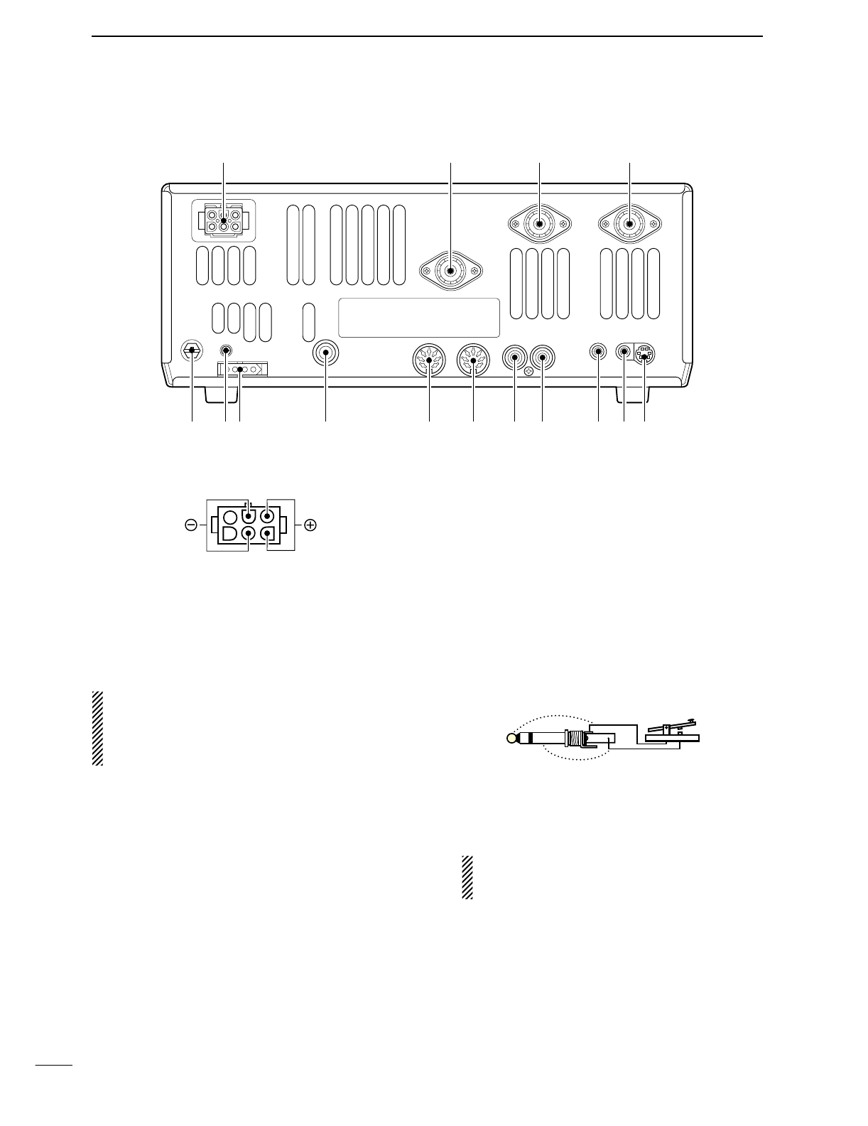
■Rear panel
qDC POWER SOCKET [DC 13.8V] (pgs. 14, 16)
Accepts 13.8 V DC through the supplied DC power
cable (OPC-025D).
wANTENNA CONNECTOR [ANT 144MHz]
eANTENNA CONNECTOR 2 [ANT2]
rANTENNA CONNECTOR 1 [ANT1]
(pgs. 14, 15, 17, 74)
Accept a 50 Ωantenna with a PL-259 connector.
•[ANT 144MHz] for 144 MHz band only; [ANT1]
When using an optional AH-4 HF/50 MHz AUTO-
MATIC ANTENNA TUNER, connect it to the [ANT1]
connector. The internal antenna tuner activates for
[ANT2] and deactivates for [ANT1] when connecting
the AH-4.
tDATA SOCKET [DATA] (pgs. 15, 77)
Connects a TNC (Terminal Node Controller), etc. for
data communications.
•See p. 8 for connector information.
yEXTERNAL SPEAKER JACK [EXT SP]
(pgs. 15, 100)
Accepts a 4–8 Ωspeaker.
u
CI-V REMOTE CONTROL JACK [REMOTE] (p. 94)
➥Designed for use with a personal computer for re-
mote control of transceiver functions.
➥Used for transceive operation with another Icom
CI-V transceiver or receiver.
iSEND CONTROL JACK [SEND] (p. 17)
Goes to ground while transmitting to control exter-
nal equipment such as a linear amplifier.
•Max. control level: 16 V DC/0.5 A
oALC INPUT JACK [ALC] (p. 17)
Connects to the ALC output jack of a non-Icom lin-
ear amplifier.
!0 ACCESSORY SOCKET 2 [ACC(2)]
!1 ACCESSORY SOCKET 1 [ACC(1)]
Enable connection of external equipment such as a
linear amplifier, an automatic antenna selector/
tuner, TNC for data communications, etc.
•See p. 8 for socket information.
!2 STRAIGHT KEY JACK [KEY] (p. 14)
Accepts a straight key or external electronic keyer
with 1⁄4inch standard plug.
•[ELEC-KEY] on the front panel can be used for a straight
key or external electronic keyer. Deactivate the internal
electronic keyer in keyer set mode. (p. 34)
!3 TUNER CONTROL SOCKET [TUNER]
(pgs. 15, 76)
Accepts the control cable from an optional AH-4
HF/50 MHz AUTOMATIC ANTENNA TUNER.
If you use an external electronic keyer, make
sure the voltage retained by the keyer is less
than 0.4 V when the key is ON.
!4 CALIBRATION POT [CAL] (p. 93)
This is used for frequency calibration.
•The transceiver has been adjusted and calibrated thor-
oughly at the factory. Under normal circumstances, the
frequency does not need to be re-calibrated.
!5 GROUND TERMINAL [GND] (pgs. 13, 14)
Connect this terminal to a ground to prevent electri-
cal shocks, TVI, BCI and other problems.
(+)
(_)
Rear panel view
!5 !3 t
r
!2 !1 !0 o i u y
qwe
!4
7
1PANEL DESCRIPTION
8
1
PANEL DESCRIPTION
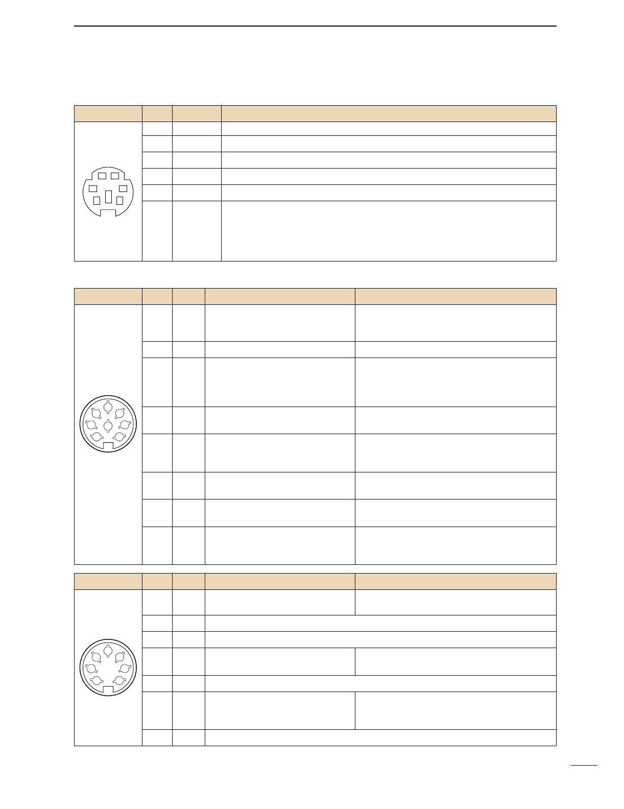
DDATA SOCKET
DACC SOCKETS
ACC (1)
PIN No.
NAME DESCRIPTION SPECIFICATIONS
1
2
3
45
67
8
“High” level : More than 2.4 V
1 RTTY Controls RTTY keying “Low” level : Less than 0.6 V
Output current : Less than 2 mA
2 GND Connects to ground. Connected in parallel with ACC(2) pin 2.
Input/output pin. (HF/50 MHz only) Ground level : –0.5 V to 0.8 V
3
HSEND
Goes to ground when transmitting. Output current : Less than 20 mA
When grounded, transmits. Input current (Tx) : Less than 200 mA
Connected in parallel with ACC(2) pin 3.
4 MOD Modulator input. Input impedance : 10 kΩ
Connects to a modulator. Input level : Approx. 100 mV rms
AF detector output. Output impedance : 4.7 kΩ
5 AF Fixed, regardless of [AF] position in Output level : 100–300 mV rms
default settings. (see notes below)
6 SQLS Squelch output. SQL open : Less than 0.3 V/5 mA
Goes to ground when squelch opens.
SQL closed : More than 6.0 V/100 µA
7 13.8 V 13.8 V output when power is ON. Output current : Max. 1 A
Connected in parallel with ACC(2) pin 7.
Control voltage : –4 V to 0 V
8 ALC ALC voltage input. Input impedance : More than 10 kΩ
Connected in parallel with ACC(2) pin 5.
ACC (2)
PIN No.
NAME DESCRIPTION SPECIFICATIONS
1
2
3
45
67
1 8 V Regulated 8 V output. Output voltage : 8 V ±0.3 V
Output current : Less than 10 mA
2 GND Same as ACC(1) pin 2.
3
HSEND
Same as ACC(1) pin 3.
4 BAND Band voltage output. Output voltage : 0 to 8.0 V
(Varies with amateur band)
5 ALC Same as ACC (1) pin 8.
Input/output pin (144 MHz only) Ground level : –0.5 V to +0.8 V
6
VSEND
Goes to ground when transmitting. Output current : Less than 20 mA
When grounded, transmits. Input current (Tx) : Less than 200 mA
7
13.8 V
Same as ACC(1) pin 7.
Rear panel view
Rear panel view
DATA
PIN No.
NAME DESCRIPTION
12
34
56
1 DATA IN Input terminal for data transmit. (1200 bps: AFSK/9600 bps: G3RUH, GMSK)
2 GND Common ground for DATA IN, DATA OUT and AF OUT.
3 PTT P PTT terminal for packet operation. Connect ground to transmit data.
4 DATA OUT Data out terminal for 9600 bps operation only.
5 AF OUT Data out terminal for 1200 bps operation only.
Squelch out terminal. Becomes high (+8 V) when the transceiver receives a signal
which opens the squelch.
6P SQL •To avoid unnecessary TNC transmission, connect squelch to the TNC to inhibit trans-
mission when receiving signals.
•Keep audio output at a normal level, otherwise a “P SQLsignal will not be output.
Rear panel view
9
1PANEL DESCRIPTION
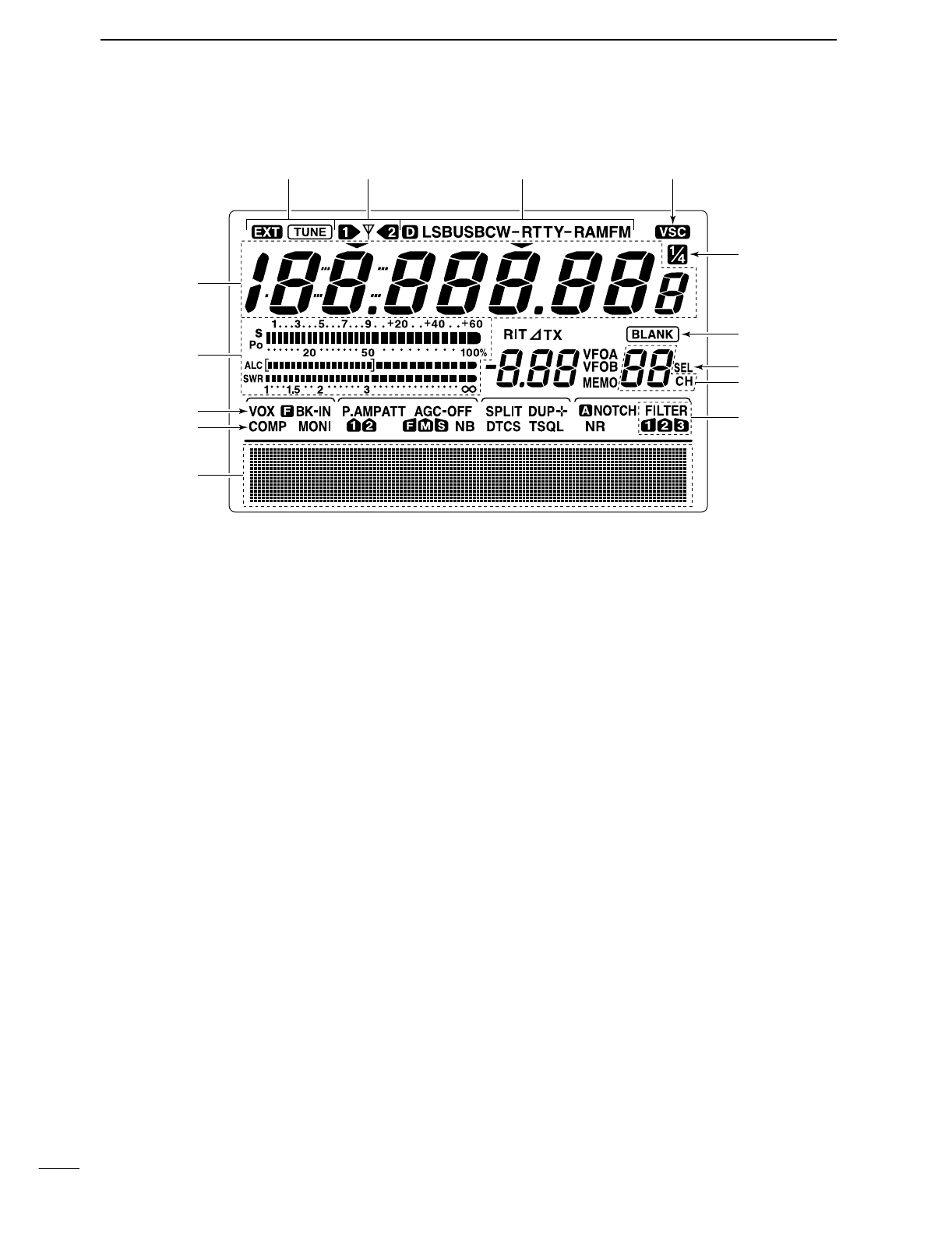
■LCD display
qFREQUENCY READOUTS
Show the operating frequency.
wMULTI-FUNCTION METER INDICATION
➥Shows receiving signal strength, etc. during re-
ceive.
➥Shows transmit output power, ALC and SWR dur-
ing transmit.
eVOX INDICATOR (p. 54)
Appears when the VOX function is activated.
r
MICROPHONE COMPRESSOR INDICATOR (p. 58)
Appears when the microphone compressor is acti-
vated.
tMULTI-FUNCTION SWITCH INDICATOR (p. 11)
Indicates the functions assigned to the multi-func-
tion switches ([F1]–[F5]).
yDSP FILTER INDICATOR (p. 50)
Shows the selected IF filter.
uMEMORY CHANNEL READOUTS (p. 62)
Show the selected memory channel.
iSELECT MEMORY CHANNEL INDICATOR (p. 72)
Appears when the selected memory channel is set
as a select memory channel.
oBLANK MEMORY INDICATOR (p. 62)
Appears when the selected memory channel is
blank.
!0 1⁄4TUNING DIAL SPEED INDICATOR (p. 21)
Appears when the tuning dial speed is set so that
one rotation is equal to 1⁄4of the normal rotation.
!1 VOICE SQUELCH CONTROL INDICATOR (p. 54)
Appears during VSC (Voice Squelch Control) func-
tion is activated.
!2 MODE INDICATORs (p. 23)
Shows the selected operating mode.
•“D” appears when SSB data, AM data or FM data mode
is selected.
!3 ANTENNA INDICATOR (p. 75)
Indicate which antenna connector is use for
HF/50 MHz.
!4 ANTENNA TUNER INDICATORS (pgs. 75, 76)
➥“TUNE” appears when the antenna tuner is ON;
“TUNE” appears and flashes during manual tun-
ing.
➥“EXT” appears when the optional AH-4 external
antenna tuner is connected to [ANT1].
q
w
t
!0
o
i
u
y
!1!2!3!4
e
r
10
1
PANEL DESCRIPTION
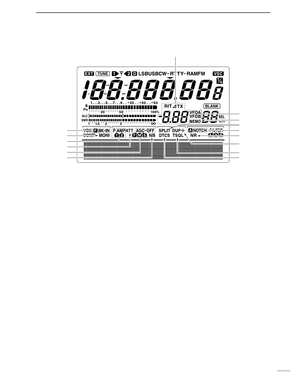
■LCD display (continue)
!5 BREAK-IN INDICATORS (p. 56)
➥“FBK-IN” appears when the full break-in function
is activated.
➥“BK-IN” appears when the semi break-in function
is activated.
!6 MONITOR INDICATORS (p. 57)
Appears when the monitor function is activated.
!7 PREAMP INDICATORS (p. 48)
Appears when the preamp is activated.
!8 ATTENUATOR INDICATORS (p. 48)
Appears when the attenuator is activated.
!9 AGC INDICATORS (p. 49)
Shows the selected AGC time constant.
•“F” for AGC fast; “M” for AGC middle; “S” for AGC
slow; “-OFF” for AGC OFF.
@0 NOISE BLANKER INDICATOR (p. 51)
Appears when the noise blanker is activated.
@1 DTCS INDICATOR (p. 43)
Appears during DTCS operation.
@2 TONE SQUELCH INDICATORS
➥“T” appears when the repeater tone is activated.
(p. 44)
➥“TSQL” appears during tone squelch operation.
(p. 42)
@3 DUPLEX INDICATOR (p. 44)
“DUP–” or “DUP+” appears during repeater opera-
tion.
@4 NOISE REDUCTION INDICATOR (p. 53)
Appears when the noise reduction is activated.
@5 NOTCH INDICATORS (p. 53)
➥“NOTCH” appears when the manual notch func-
tion is activated.
➥“ANOTCH” appears when the automatic notch
function is activated.
@6 SPLIT INDICATOR (pgs. 58, 59)
Appears during split operation.
@7 MEMORY INDICATOR (p. 62)
Appears during memory mode.
@8 VFO INDICATORS (p. 20)
Indicates whether VFO A or VFO B is selected.
@9 RIT/∂TX INDICATORS (pgs. 48, 56)
Appears during RIT or ∂TX operation and indicate
the frequency offset.
!7
!8
!9
@0
@7
@6
@5
@4
@2
@3
@1
@9
!5
!6
@8
11
1PANEL DESCRIPTION
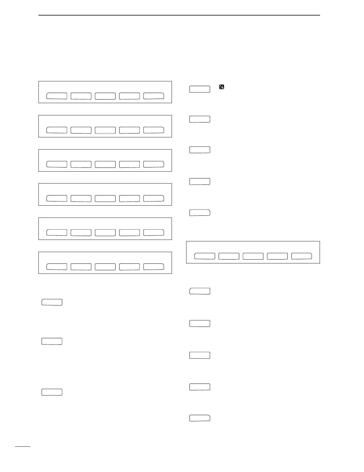
■Multi function switches
DM1 FUNCTIONS
During SSB operation
During SSB data operation
During CW operation
During RTTY operation
During AM operation
During FM operation
AGC (p. 49)
➥Push momentarily to changes the time
constant of the AGC circuit.
➥Push for 1 sec. to enter to the AGC set
mode.
DUPLEX (p. 44)
➥Push momentarily to selects the duplex
direction or turn the function OFF.
•“DUP–” or “DUP+” indicator appears during
duplex operation.
➥Push for 1 sec. to turn the one-touch re-
peater function ON/OFF.
SPEECH COMPRESSOR (p. 58)
➥Push momentarily to turn the speech
compressor function ON/OFF.
•“COMP” indicator appears when the speech
compressor is ON.
➥Push for 1 sec. to enter to the compres-
sor set mode.
1⁄4FUNCTION (p. 21)
Push to turn the 1⁄4function ON/OFF.
•“ ” indicator appears when the 1⁄4function is
ON.
TRANSMISSION BANDWIDTH (p. 58)
Push to select the transmission bandwidth.
•Bandwidth is selectable from narrow, middle
and wide.
MEMORY KEYER MENU (p. 29)
Push to select the memory keyer or keyer
send menu, depending on the KEYER
1st Menu setting in the set mode (p. 86).
RTTY MENU (p. 36)
Push to select the RTTY menu.
BAND SCOPE FUNCTION (p. 47)
Push to select the band scope screen.
DM2 FUNCTIONS
SCAN MENU (p. 70)
Push to select the scan menu.
MEMORY NAME MENU (p. 67)
Push to select the memory name screen.
SWR GRAPH FUNCTION (p. 61)
Push to indicates the SWR graph screen.
TONE CONTROL SET MODE (p. 88)
Push to enter the audio tone set mode.
VSC FUNCTION (p. 54)
Push to turns the VSC (Voice Squelch
Control) function ON and OFF.
F
5
VSC
F
4
TCN
F
3
SWR
F
2
MEM
F 1
SCN
F 1
F
2F
3
F
4
F
5
SCN MEM SWR TCN VSC
F
5
SCP
F
4
RTY
F
4
KEY
F
4
TBW
F
3
1/4
F
3
CMP
F
2
DUP
F 1
AGC
F 1
F
2F
3
F
4
F
5
AGC DUP CMP TON SCP
F 1
F
2F
3
F
4
F
5
AGC DUP CMP SCP
F 1
F
2F
3
F
4
F
5
AGC DUP 1/4 RTY SCP
F 1
F
2F
3
F
4
F
5
AGC DUP 1/4 KEY SCP
F 1
F
2F
3
F
4
F
5
AGC DUP 1/4 SCP
F 1
F
2F
3
F
4
F
5
AGC DUP CMP TBW SCP
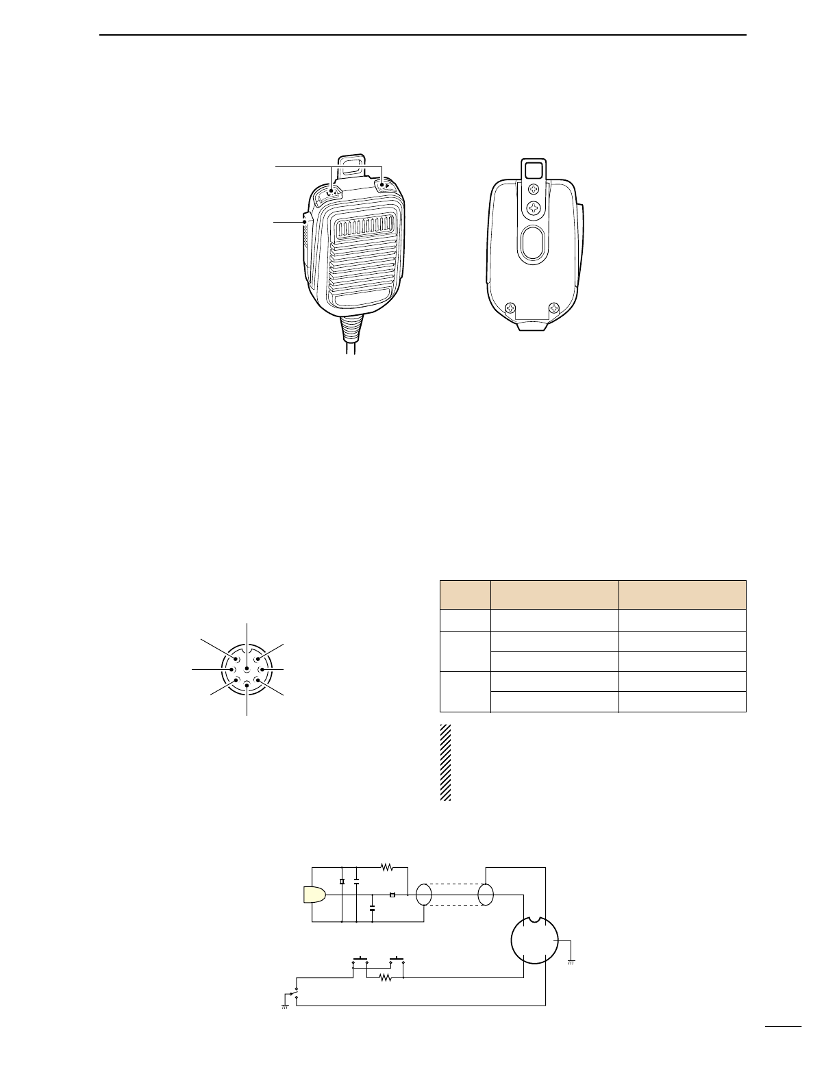
■Microphone (HM-36)
qUP/DOWN SWITCHES [UP]/[DN]
Change the selected readout frequency or memory
channel.
•Continuous pushing changes the frequency or memory
channel number continuously.
•While pushing [XFC], the transmit readout frequency can
be controlled while in spilt frequency operation.
•The [UP]/[DN] switch can simulate a key paddle. Preset
in the keyer set mode. (p. 34)
•MICROPHONE CONNECTOR
(Front panel view)
•HM-36 SCHEMATIC DIAGRAM
wPTT SWITCH
Push and hold to transmit; release to receive.
CAUTION: DO NOT short pin 2 to ground as this
can damage the internal 8 V regulator.
NOTE: DC voltage is applied to pin 1 for micro-
phone operation. Take care when using a non-Icom
microphone.
y GND (PTT ground)
t PTT
r Main readout squelch switch
q Microphone input
w +8 V DC output
e Frequency up/down
u GND
(Microphone ground)
i Main readout AF output
(varies with [AF]/[BAL])
q
w
[MIC] FUNCTION DESCRIPTION
Pin No.
w+8 V DC output Max. 10 mA
eFrequency up Ground
Frequency down Ground through 470 Ω
rSquelch open “Low” level
Squelch closed “High” level
+
+
q
w
ert
y
u
i
4700p
4700p
10µ
0.33µ
MICROPHONE
MIC
ELEMENT
2k
470
DOWN UP
PTT RECEIVE
TRANSMIT
MICROPHONE CABLE MICROPHONE PLUG
12
1
PANEL DESCRIPTION
2
13
INSTALLATION AND CONNECTIONS
■Unpacking
After unpacking, immediately report any damage to the
delivering carrier or dealer. Keep the shipping cartons.
For a description and a diagram of accessory equip-
ment included with the IC-746PRO, see ‘Supplied ac-
cessories’on p. ii of this manual.
■Selecting a location
Select a location for the transceiver that allows ade-
quate air circulation, free from extreme heat, cold, or
vibrations, and away from TV sets, TV antenna ele-
ments, radios and other electro magnetic sources.
The base of the transceiver has an adjustable stand
for desktop use. Set the stand to one of two angles de-
pending on your operating conditions.
■Grounding
To prevent electrical shock, television interference
(TVI), broadcast interference (BCI) and other prob-
lems, ground the transceiver through the GROUND
terminal on the rear panel.
For best results, connect a heavy gauge wire or strap
to a long earth-sunk copper rod. Make the distance be-
tween the [GND] terminal and ground as short as pos-
sible.
RWARNING: NEVER connect the [GND]
terminal to a gas or electric pipe, since the connec-
tion could cause an explosion or electric shock.
■Antenna connection
For radio communications, the antenna is of critical im-
portance, along with output power and sensitivity. Se-
lect antenna(s), such as a well-matched 50 Ωantenna,
and feedline. 1.5:1 or better of Voltage Standing Wave
Ratio (VSWR) is recommended for your desired band.
Of course, the transmission line should be a coaxial
cable.
When using 1 antenna, use the [ANT1] connector.
CAUTION: Protect your transceiver from lightning
by using a lightning arrestor.
Antenna SWR
Each antenna is tuned for a specified frequency
range and SWR may be increased out-of-range.
When the SWR is higher than approx. 2.0:1, the
transceiver’s power drops to protect the final transis-
tor. In this case, an antenna tuner is useful to match
the transceiver and antenna. Low SWR allows full
power for transmitting even when using the antenna
tuner. The IC-746PRO has an SWR meter to moni-
tor the antenna SWR continuously.
PL-259 CONNECTOR INSTALLATION EXAMPLE
30 mm ≈9⁄8in 10 mm ≈3⁄8in 1–2 mm ≈1⁄16 in
30 mm
10 mm (soft solder)
10 mm
1–2 mm
solder solder
Soft
solder
Coupling ring
Slide the coupling ring
down. Strip the cable
jacket and soft solder.
Slide the connector
body on and solder it.
Screw the coupling
ring onto the
connector body.
Strip the cable as
shown at left. Soft sol-
der the center con-
ductor.
q
w
e
r
2
14
INSTALLATION AND CONNECTIONS
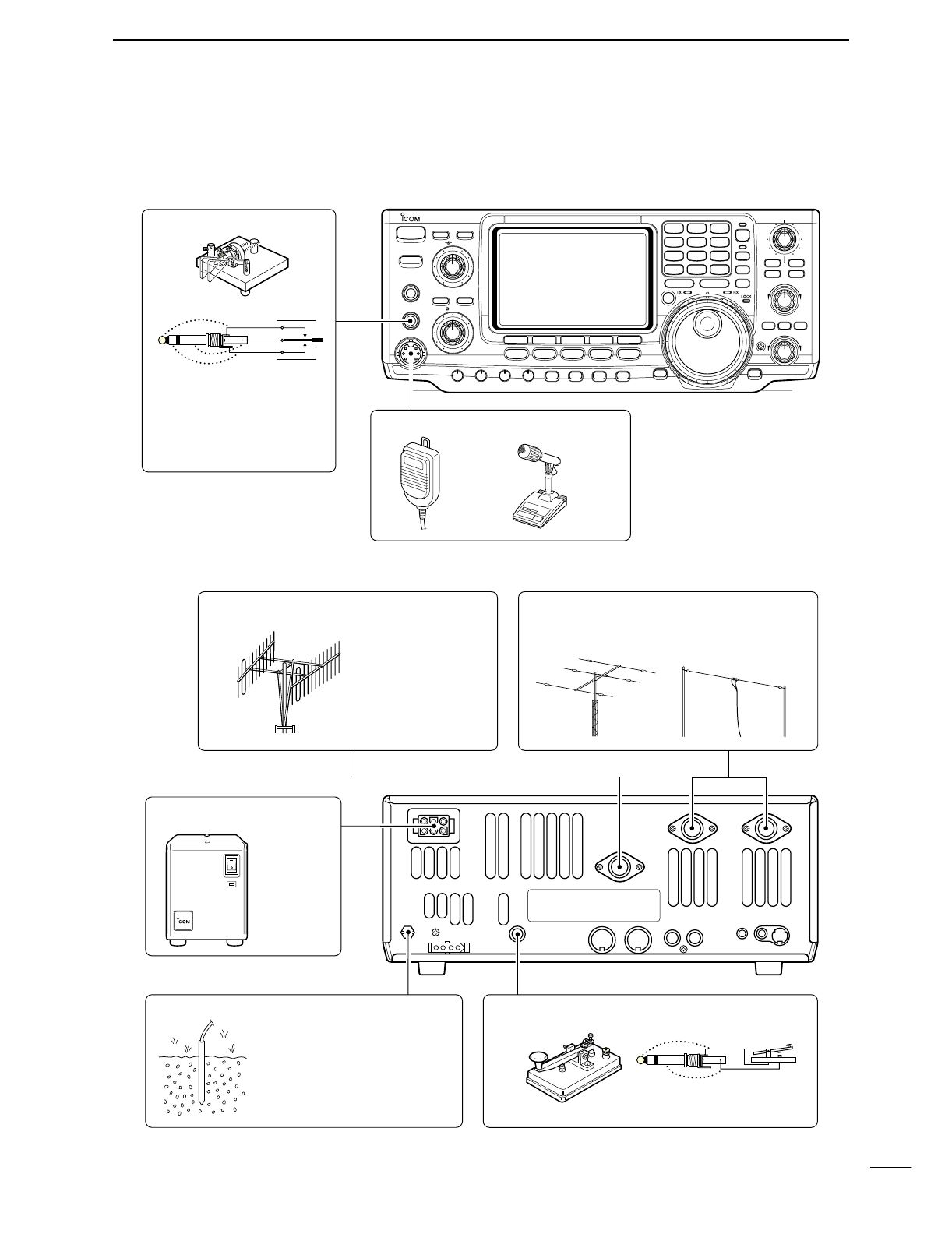
■Required connections
•Front panel
•Rear panel
i746PRO
POWER
F
1
MENU SSB
F
2
CW/RTTY
F
3
AM/FM
F
4
FILTER
F
5
XFC
MP-W
GENE
50
MP-R
0
21
7
24
8
28
9
10
4
14
5
18
6
1.8
1
3.5
2
7
3
144
ENT
TS
A/B
SPLIT
F-INP
V/M
M-CL
PBTC
MW
TWIN PBT
M-CH
LOCK/
SPCH
∂TXRIT
CLEAR
RIT/∂TX
CALL
MONITOR
VOX/BK-IN
NB
P.AMP/ATT
KEY SPEED
CW PITCH
RF PWR
MIC GAIN
HF/VHF TRANSCEIVER
TRANSMIT
PHONES
ELEC-KEY
MIC
TUNER
ANT
NR
NOTCH
AF
RF/SQL
NR
A/NOTCH
CW KEY
MICROPHONES (p. 100)
A straight key can be used
when the internal electronic
keyer is turned OFF in keyer
set mode. (p.34)
HM-36 SM-20
(optional)
(dot)
(com)
(dash)
GROUND (p. 13)
Use the heaviest gauge wire or
strap available and make the
connection as short as possible.
Grounding prevents electrical
shocks, TVI and other problems.
ANTENNA 1, 2 (pgs. 13, 74)
[Example]: ANT1 for 1.8–18 MHz bands
ANT2 for 21–50 MHz bands
DC POWER SUPPLY
STRAIGHT KEY
PS-125
(Optional)
144 MHz ANTENNA (pgs. 13, 74)
Connect a VHF
(60–144 MHz)
antenna;
impedance: 50 Ω.
(+)
(_)
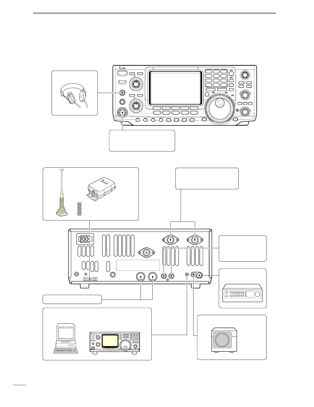
■Advanced connections
•Front panel
•Rear panel
15
2INSTALLATION AND CONNECTIONS
POWER
TRANSMIT
PHONES
ELEC-KEY
MIC
NR
A/NOTCH
TUNER
ANT
HF/VHF TRANSCEIVER
NR
NOTCH
AF
MIC GAIN
RF PWR
CW PITCH
F 1
F
2F
3
F
4
F
5
XFC
MP-W
GENE
50
0
21
7
24
8
28
9
14
5
10
4
18
6
3.5
2
1.8
1
7
3
144
ENT
MP-R
TX RX LOCK
TWIN PBT
M-CH
RIT
CLEAR
∂TX
RIT/∂TX
TS
SPLIT
PBTC
F-INP
A/B
V/M
MW
M-CL
KEY SPEED
P.AMP/ATT
NB
VOX/BK-IN
MONITOR
CALL
LOCK/
SPCH
RF/SQL
i746PRO
MENU SSB
CW/RTTY
AM/FM
FILTER
HEADPHONES
MIC
The AFSK modulation signal
can be input from [MIC]. (p. 77)
AH-2b
AH-4 (p. 76) ANTENNA 1, 2 (p. 17)
Connects a linear amplifier,
antenna selector, etc.
[SEND], [ALC] (p. 17)
Used for connecting a
non-Icom linear ampli-
fier.
When using the AH-4, it must
be connected to the [ANT1]
connector.
[REMOTE] (p. 94)
Used for computer control and transceive operation.
[DATA] (p. 77)
EXTERNAL SPEAKER (p. 100)
SP-21
ACC SOCKETS (pgs. 8, 77)
16
2
INSTALLATION AND CONNECTIONS
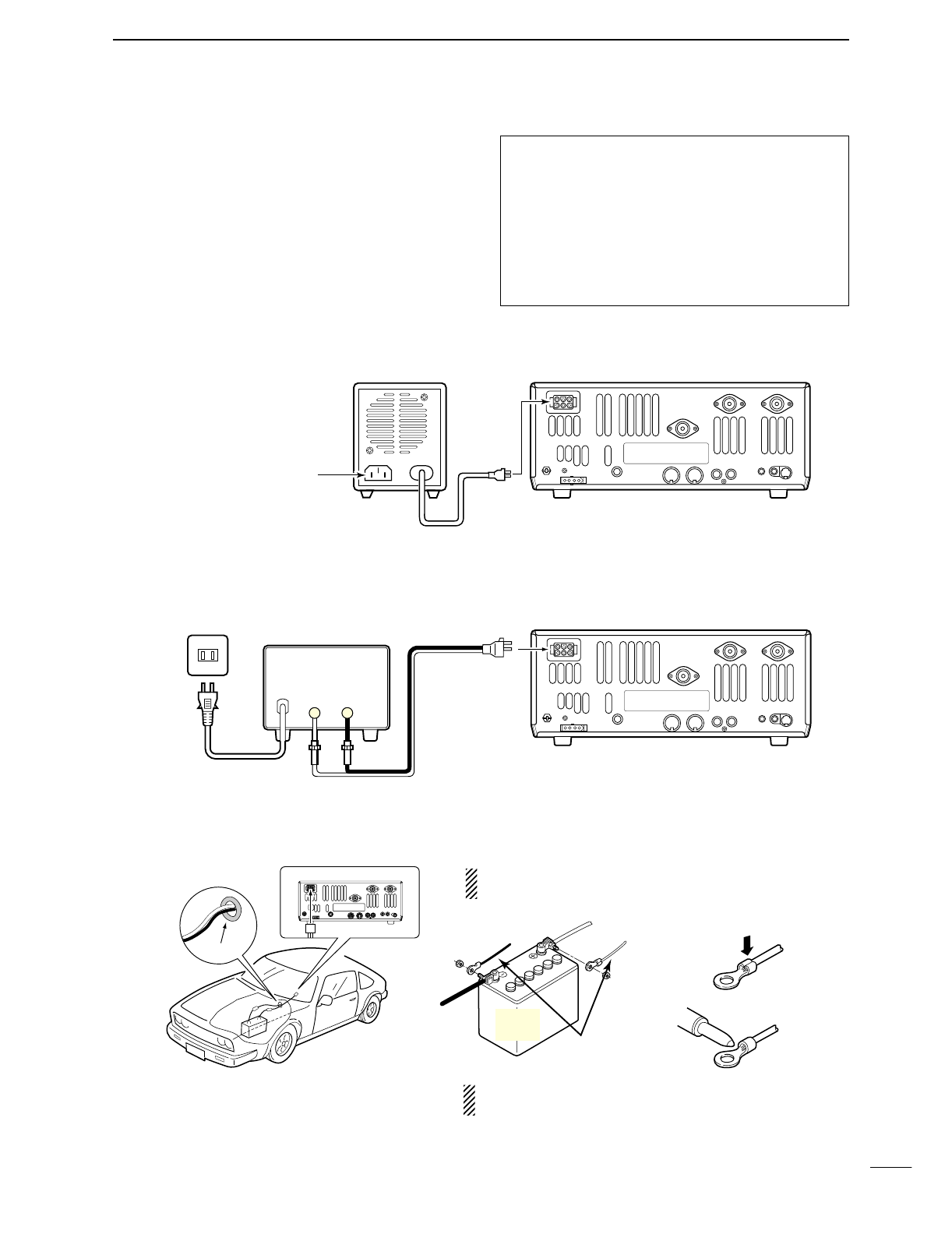
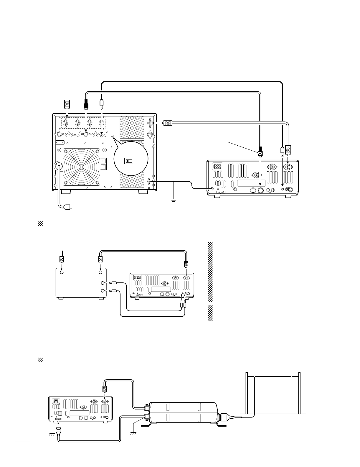
■Power supply connections
Use an optional DC power supply with a 25 A capacity
and above when operating the transceiver with AC
power. Refer to the diagrams below.
CONNECTING PS-125 DC POWER SUPPLY
CONNECTING A DC POWER SUPPLY
CONNECTING A VEHICLE BATTERY
30 A fuses
AC cable
Transceiver
AC outlet A DC power supply
13.8 V; at least 23 A
Black
_
Red
+
to DC power
socket
Supplied
DC power cable
12 V
battery Supplied
DC power cable
+ red
_ black Crimp
Solder
Grommet
NEVER connect to
a 24 V battery.
NOTE: Use terminals for
the cable connections.
NEVER connect to a battery without supplied DC
fuses, otherwise a fire hazard may occur.
PS-125
Connect to an AC outlet
using the supplied AC cable.
DC power cable
DC power
socket
Transceiver
CAUTION: Before connecting the DC power
cable, check the following important items. Make
sure:
•The [POWER] switch is OFF.
•Output voltage of the power source is 12–15 V
when you use a non-Icom power supply.
•DC power cable polarity is correct.
Red : positive +terminal
Black : negative _terminal
17
2INSTALLATION AND CONNECTIONS
■Linear amplifier connections
CONNECTING THE IC-PW1
Turn OFF the transceiver’s antenna tuner while tuning the IC-PW1’s tuner.
CONNECTING A NON-ICOM LINEAR AMPLIFIER
RWARNING:
Set the transceiver output power and linear
amplifier ALC output level referring to the linear
amplifier instruction manual.
The ALC input level must be in the range 0 V to
–4 V, and the transceiver does not accept pos-
itive voltage. Non-matched ALC and RF power
settings could cause a fire or ruin the linear
amplifier.
The specifications for the SEND relay are
16 V/DC 0.5 A. If this level is exceeded, a large
external relay must be used.
■External antenna tuner connection
CONNECTING THE AH-4
The AH-4 must be connected to [ANT1].
To an
antenna ACC(1)
ANT
ANT1
ACC(2)
INPUT1
REMOTE
EXCITER
1 1&2
GND
GND
IC-PW1
AC outlet
(Non-European versions: 100—120/220—240 V
European version : 230 V)
Ground Transceiver
REMOTE
Remote control cable (supplied with the IC-PW1)
ACC cable (supplied with the IC-PW1)
Be sure to connect the cable
to the 7-pin ACC(2) jack.
Coaxial cable
(supplied with the IC-PW1)
Coaxial cable (from AH-4)
ANT1
Transceiver
Ground AH-4
Control cable
Long wire or optional AH-2b
50 Ω coaxial cable
Non-Icom linear amplifier SEND
ALC
To an
antenna
RF OUTPUT RF INPUT
ALC
SEND
ANT1
Transceiver
Use the [ANT1] connector when connecting a linear
amplifier.
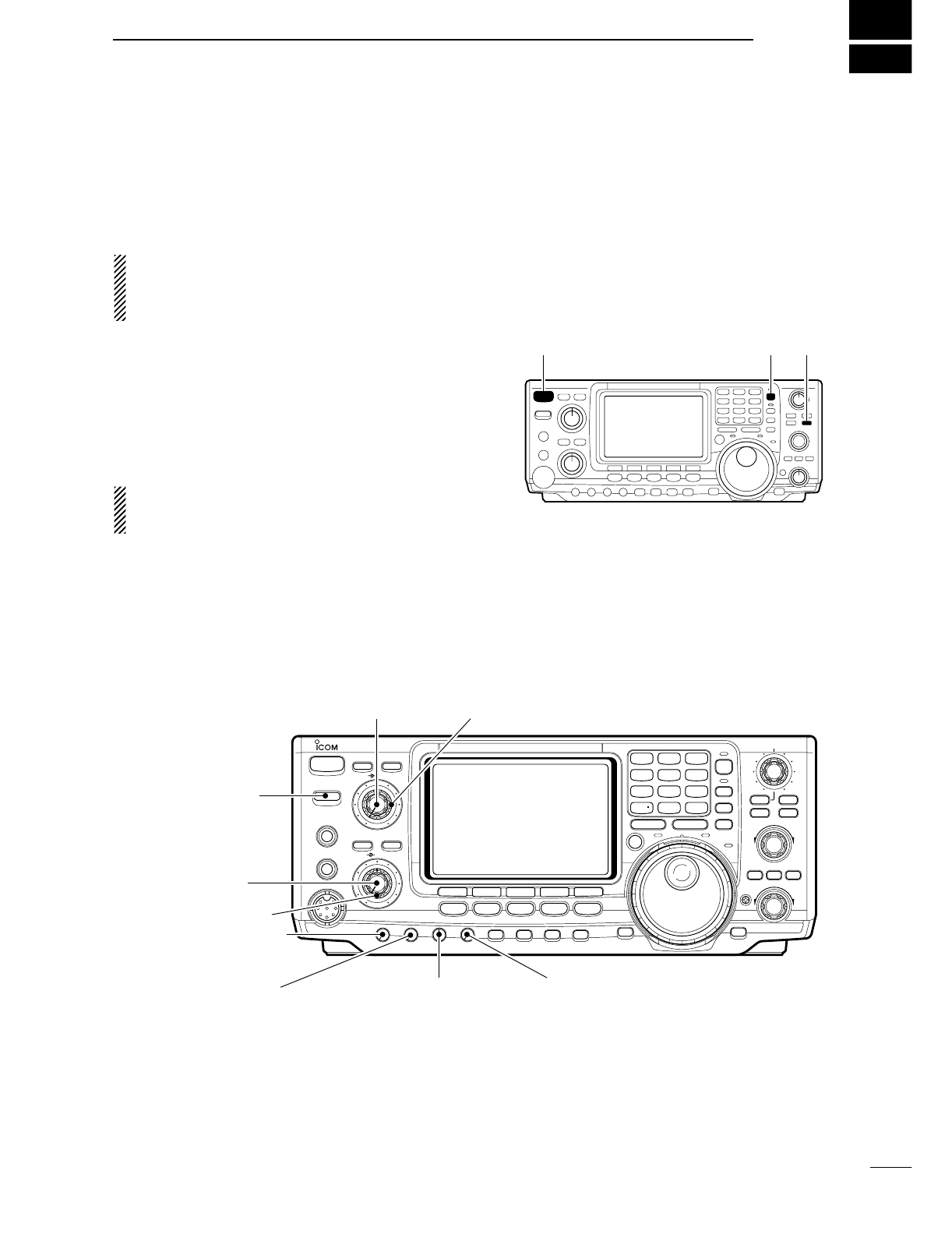
Before first applying power, make sure all connections
required for your system are complete by referring to
Chapter 2. Then, reset the transceiver using the fol-
lowing procedure.
NOTE: When first applying power or when operat-
ing in cold environments, the display may flicker or
appear faint. This is normal and will disappear once
the transceiver has warmed up.
qMake sure the transceiver power is OFF.
wWhile pushing [M-CL] and [F-INP], push [POWER]
for 1 sec. to turn power ON.
•The internal CPU is reset.
•The transceiver displays its initial VFO frequency when
resetting is complete.
eCorrect the set mode settings after resetting, if de-
sired.
Resetting CLEARS all programmed contents in
memory channels and returns programmed values
in set mode to default values.
3
18
BASIC OPERATION
■When first applying power (CPU resetting)
■Initial settings
After resetting the transceiver, set controls and
switches as shown in the figure below. CW : Clockwise
CCW : Counterclockwise
POWER
TRANSMIT
PHONES
ELEC-KEY
MIC
NR
A/NOTCH
TUNER
ANT
HF/VHF TRANSCEIVER
NR
NOTCH
AF
MIC GAIN
RF PWR
CW PITCH
F 1
F
2F
3
F
4
F
5
XFC
MP-W
GENE
50
0
21
7
24
8
28
9
14
5
10
4
18
6
3.5
2
1.8
1
7
3
144
ENT
MP-R
TX RX LOCK
TWIN PBT
M-CH
RIT
CLEAR
∂TX
RIT/∂TX
TS
SPLIT
PBTC
F-INP
A/B
V/M
MW
M-CL
KEY SPEED
P.AMP/ATT
NB
VOX/BK-IN
MONITOR
CALL
LOCK/
SPCH
RF/SQL
i746PRO
MENU SSB
CW/RTTY
AM/FM
FILTER
[NR]: Max. CCW [NOTCH]: Max. CCW
[AF]: Max. CCW
[TRANSMIT]: OFF
[MIC GAIN]: Max. CCW
[RF PWR]: Max. CCW [CW PITCH]: 12 o’clock
[RF/SQL]: 12 o’clock
[KEY SPEED]: Max. CCW
[POWER] [F-INP] [M-CL]
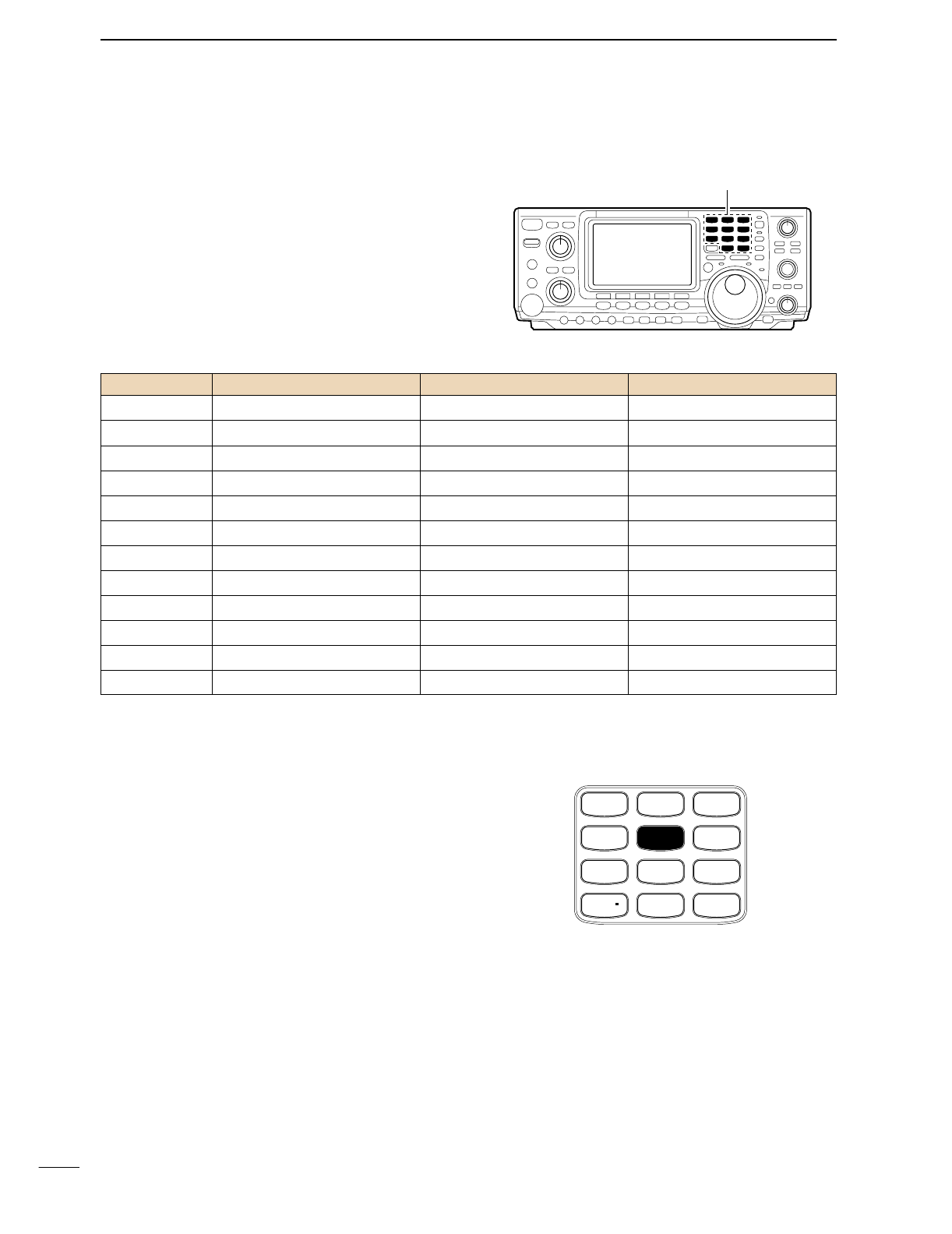
19
3BASIC OPERATION
■Selecting an operating band
The transceiver has a triple band stacking register.
This means that the last 3 operating frequencies and
modes used on a particular band are automatically
memorized.
See the table below for a list of the bands available
and the default settings for each register.
DUsing the band stacking registers
qPush [14
5
], then select a frequency and an operat-
ing mode.
•Frequency and operating mode are memorized in the
first band stacking register.
wPush [14
5
] again, then select another frequency
and operating mode.
•This frequency and operating mode are memorized in
the second band stacking register.
ePush [14
5
] again, then select another frequency
and operating mode.
•This frequency and operating mode are memorized in
the third band stacking register.
•When a fourth frequency and operating mode are se-
lected on a band, the first register. set in step q, is over-
written.
Band keys
BAND REGISTER 1 REGISTER 2 REGISTER 3
1.8 MHz 1.900000 MHz CW 1.910000 MHz CW 1.915000 MHz CW
3.5 MHz 3.550000 MHz LSB 3.560000 MHz LSB 3.580000 MHz LSB
7 MHz 7.050000 MHz LSB 7.060000 MHz LSB 7.020000 MHz CW
10 MHz 10.120000 MHz CW 10.130000 MHz CW 10.140000 MHz CW
14 MHz 14.100000 MHz USB 14.200000 MHz USB 14.050000 MHz CW
18 MHz 18.100000 MHz USB 18.130000 MHz USB 18.150000 MHz USB
21 MHz 21.200000 MHz USB 21.300000 MHz USB 21.050000 MHz CW
24 MHz 24.950000 MHz USB 24.980000 MHz USB 24.900000 MHz CW
28 MHz 28.500000 MHz USB 29.500000 MHz USB 28.100000 MHz CW
50 MHz 50.100000 MHz USB 50.200000 MHz USB 51.000000 MHz FM
144 MHz 145.000000 MHz FM 145.100000 MHz FM 145.200000 MHz FM
General 15.000000 MHz USB 15.100000 MHz USB 15.200000 MHz USB
[Example]: 14 MHz band
GENE
50
0
21
7
24
8
28
9
14
5
10
4
18
6
3.5
2
1.8
1
7
3
144
ENT
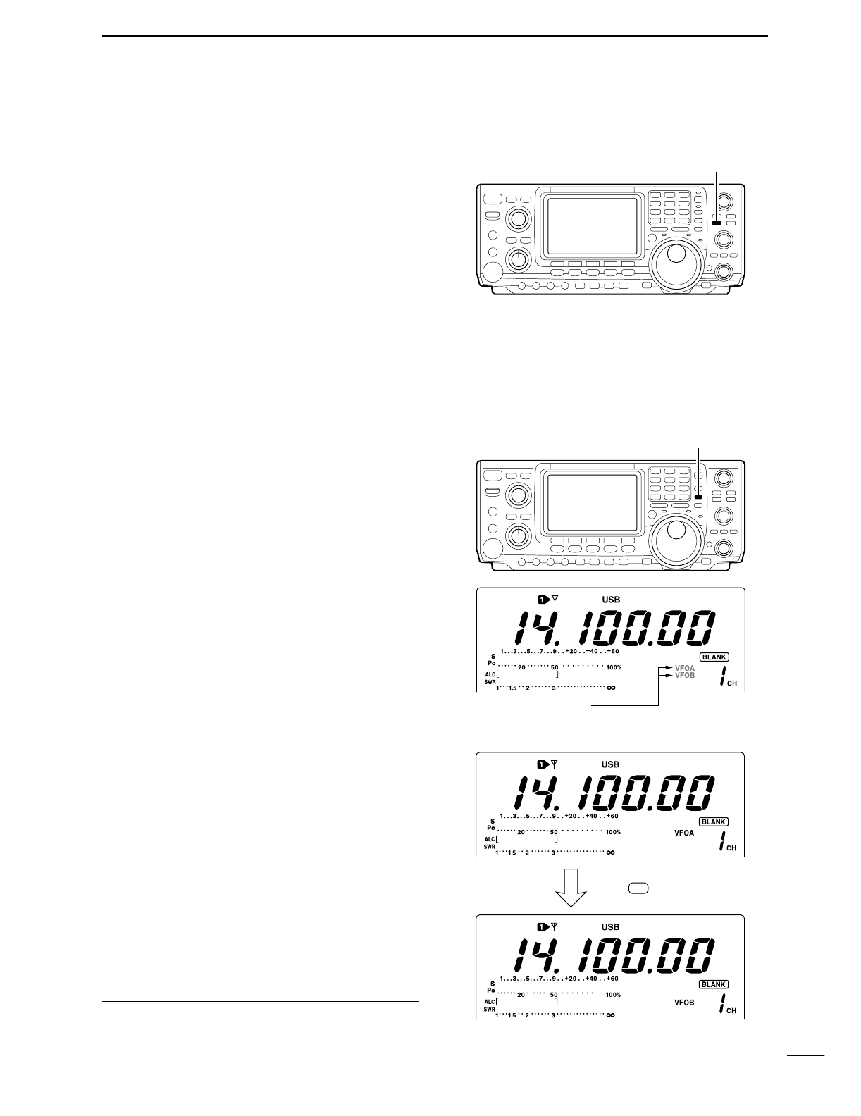
20
3
BASIC OPERATION
■Selecting VFO/memory mode
VFO is an abbreviation of Variable Frequency Oscilla-
tor, and traditionally refers to an oscillator.
➥Push [V/M] to switch between VFO and memory
modes.
•Pushing [V/M] for 1 sec. transfers the contents of the se-
lected memory channel to VFO mode (p. 65).
■VFO operation
The transceiver has 2 VFOs and are called VFO A and
VFO B. You can use the desired VFO to call up a fre-
quency and operating mode for your operation.
DSelecting the VFO A/B
➥Push [A/B] to switch between the VFO A and
VFO B.
•“VFO A” or “VFO B” appears.
DVFO equalization
➥Push [A/B] for 1 sec. to equalize the undisplayed
VFO condition to the displayed VFO.
•3 beeps sound when the VFO equalization is completed.
CONVENIENT
Use two VFOs as a quick memory
When you find a new station, but you wish to continue
searching, the Two VFO system can be used for quick mem-
ory storage.
qPush [A/B] for 1 sec. to store the displayed frequency into
the undisplayed VFO.
wContinue to searching for stations.
ePush [A/B] to retrieve the stored frequency.
rTo continue searching for station, push [A/B] again.
[A/B]
Either one is appears
Push for 1 sec.
A/B
[V/M]
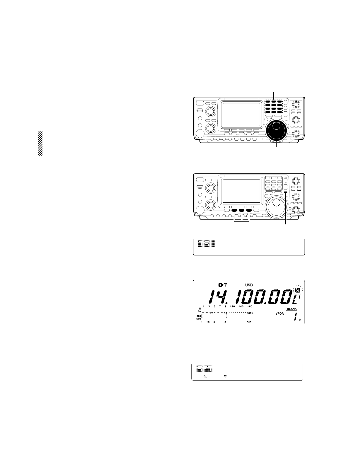
21
3BASIC OPERATION
■Frequency setting
The transceiver has several tuning methods for conve-
nient frequency tuning.
DTuning with the tuning dial
qPush the desired band key on the keypad 1–3
times.
•3 different frequencies can be selected on each band
with the band key. (p. 19)
wRotate the tuning dial to set the desired frequency.
If the dial lock function is activated, the lock indicator
lights, and the tuning dial does not function. In this
case, push [LOCK/SPCH] to deactivate the lock
function. (see p. 53 for details)
DQuick tuning step
The operating frequency can be changed in kHz steps
(0.1, 1, 5, 9, 10, 12.5, 20 or 25 kHz selectable) for
quick tuning.
qPush [SSB], [CW/RTTY] or [AM/FM] to select the
desired operation mode.
wPush [TS] momentarily to activate the quick tuning
function.
•“▼” appears.
ePush [TS] for 1 sec. to enter the tuning step set
mode.
rRotate the tuning dial to select the desired tuning
step.
tPush [TS] to exit the tuning step set mode.
D1⁄4Tuning step function (SSB data, CW and RTTY only)
While operating in SSB data/CW/RTTY, the 1⁄4function
is available for critical tuning. Dial rotation is reduced to
1⁄4of normal when the 1⁄4function is in use.
➥While M1 is selected with [MENU], push [F3 1/4]
to toggle the 1⁄4function ON and OFF.
DAuto tuning step function
When rotating the tuning dial rapidly, the tuning step
automatically changes several times as selected.
qPush [MENU] for 1 sec. to enter the set mode.
wPush [F1≤] or [F2 ≥] to select the DIAL Auto
TS item.
eRotate the tuning dial to select the function ON
(HIGH or LOW) and OFF.
•HIGH : Approx. 5 times faster
•LOW : Approx. 2 times faster
•OFF : Auto tuning step is turned OFF.
rPush [MENU] to exit the set mode.
Band keys
Tuning dial
[TS]Select mode
1kHz
SSB
1⁄4 indicator
27
HIGH
DIAL
Auto
TS
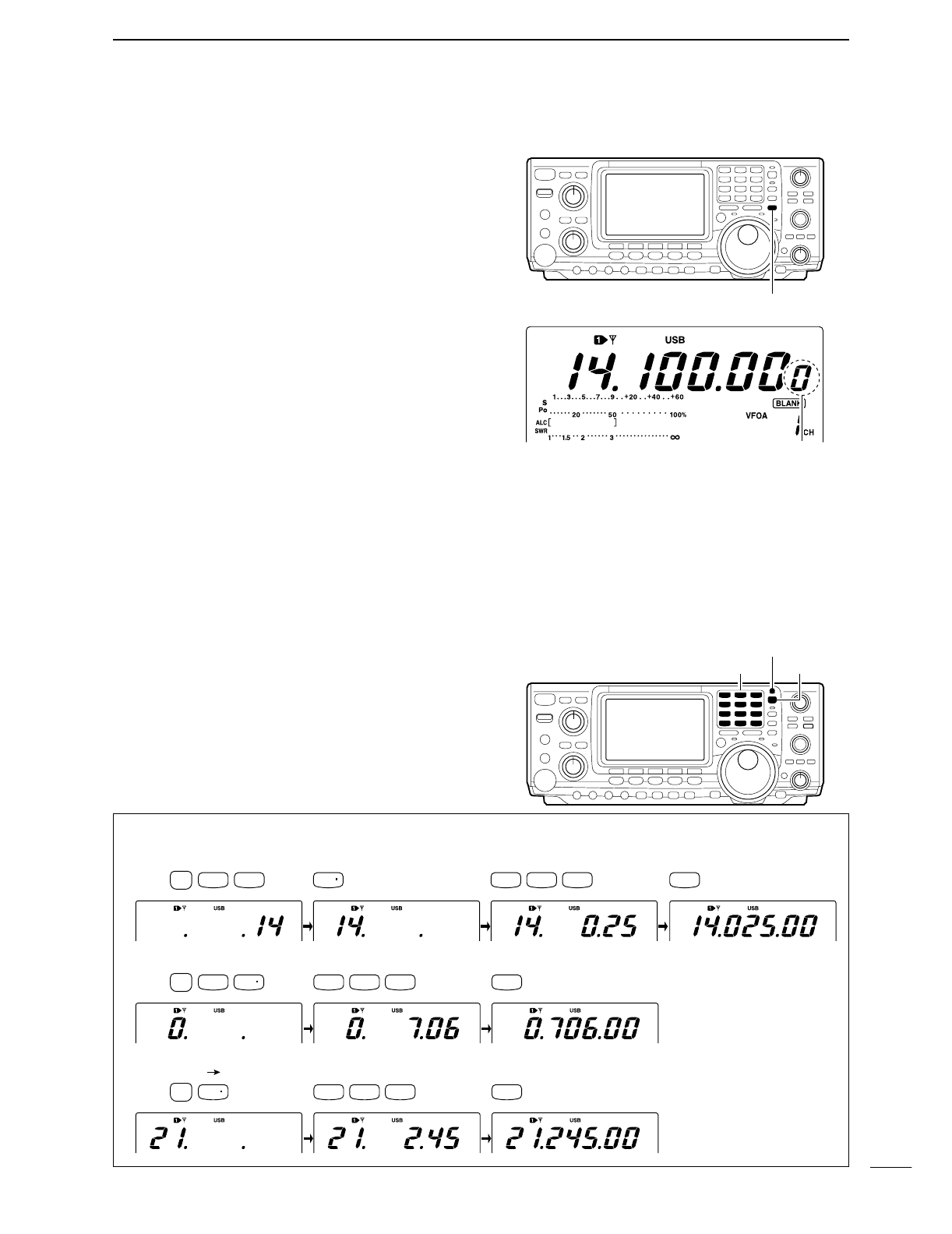
22
3
BASIC OPERATION
DSelecting the 1 Hz step
The minimum tuning step of 1 Hz can be used for fine
tuning.
qPush [TS] momentarily to turn the quick tuning step
OFF
•“▼” disappears.
wPush [TS] for 1 sec. to toggle the 1 Hz tuning step
ON and OFF.
DBand edge warning beep
When selecting a frequency that lies outside of a
band’s specified frequency range, a warning beep
sounds.
This function can be turned OFF in set mode, if de-
sired. (p. 81)
DFrequency setting with the keypad
The transceiver has a keypad for direct frequency
entry as described below.
qPush [F-INP].
•F-INP indicator lights
wInput the desired frequency.
•Input “•” (decimal point) between the MHz units and kHz
units.
ePush [144 ENT] to enter the input frequency.
•To cancel the input, push [A/B] instead of [144 ENT].
Lights when kypad input is activated.
Keypad [F-INP]
21.280 MHz 21.245 MHz
14.025 MHz
Push
[EXAMPLE]
50
0
21
7
14
5
10
4
10
4
18
6
3.5
2
1.8
1
F-INP
GENE
50
0
50
0
3.5
2
GENE
14
5
144
ENT
706 kHz
Push
144
ENT
144
ENT
F-INP
GENE
Push
F-INP
[TS]
1 Hz indicator
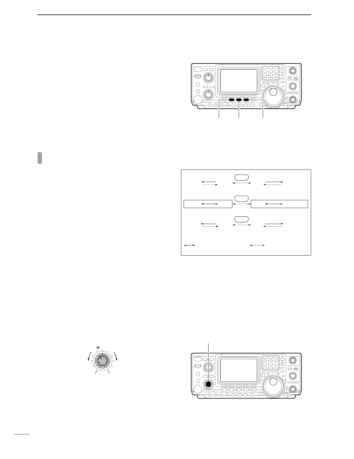
23
3BASIC OPERATION
■Operating mode selection
SSB (USB/LSB), SSB data (USB data/LSB data), CW,
CW reverse (CW-R), RTTY, RTTY-R (RTTY reverse),
AM, AM data, FM and FM data modes are available in
the IC-746PRO. Select the desired operation mode as
follows.
To select a mode of operation, push the desired mode
switch momentarily. Push the switch again to toggle
between USB and LSB, CW/CW-R and RTTY/RTTY-
R, AM and FM, if necessary. Push the switch for 1 sec.
to toggle between CW and CW-R, RTTY and RTTY-R,
or to select data mode, if necessary.
See the diagram right below for the order of selection.
Microphone signals are muted when data mode is
selected.
•Selecting SSB mode
➥Push [SSB] to select USB or LSB.
•USB is selected first during above 10 MHz; or LSB is se-
lected first during below 10 MHz operation.
•After USB or LSB is selected, push [SSB] to toggles be-
tween USB and LSB.
•After USB or LSB is selected, push [SSB] for 1 sec. to
select USB data or LSB data mode, respectively.
•Selecting CW/RTTY mode
➥Push [CW/RTTY] to select CW or RTTY.
•After CW/CW-R or RTTY/RTTY-R is selected, push
[CW/RTTY] to toggles between CW and RTTY.
•After CW or RTTY is selected, push [CW/RTTY] for
1 sec. to toggles between CW and CW reverse, or,
RTTY and RTTY reverse mode, respectively.
•Selecting AM/FM mode
➥Push [AM/FM] to select AM or FM.
•After AM or FM is selected, push [AM/FM] to toggles be-
tween AM and FM mode.
•After AM or FM is selected, push [AM/FM] for 1 sec. to
select AM data or FM data mode, respectively.
■Volume setting
➥Rotate [AF] control to output a suitable audio level.
AF RF/SQL
No audio output Max. audio output
Decreases Increases
[SSB] [CW/RTTY] [AM/FM]
SSB
CW/RTTY
AM/FM
D USB USB
CW-R CW
D AM AM
Push mode switch
for 1 sec. Push mode switch
momentarily.
LSB D LSB
RTTY RTTY-R
FM D FM
[AF] control
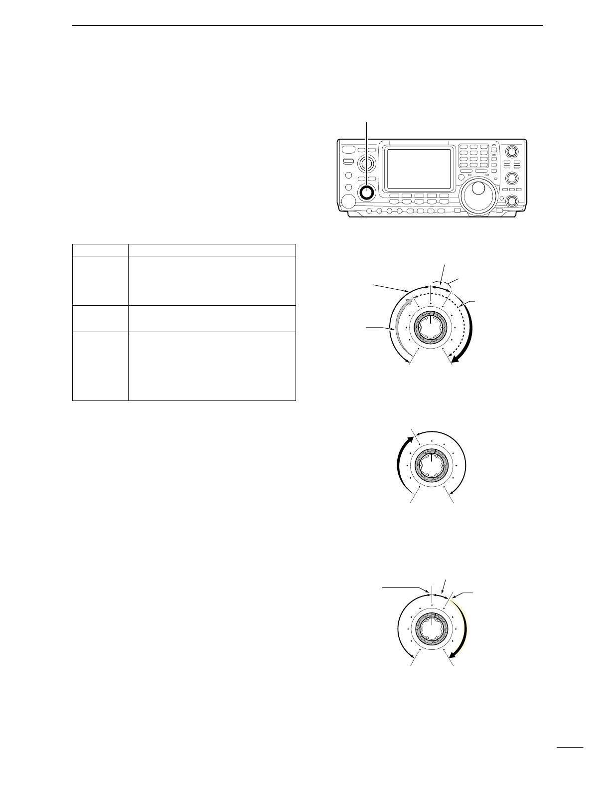
3
BASIC OPERATION
24
Adjusts the RF gain and squelch threshold level. The
squelch removes noise output from the speaker
(closed position) when no signal is received.
•The squelch is particularly effective for FM. It is also avail-
able for other modes.
•The control can be set as the RF gain control only (squelch
is fixed open) or squelch control (RF gain is fixed at maxi-
mum) in set mode (p. 81). See below right.
•The 11 to 12 o’clock position is recommended for any set-
ting of the [RF/SQL] control.
Adjusting RF gain (Receive sensitivity)
Normally, [RF/SQL] is set to the 11 o’clock position.
Rotate [RF/SQL] to the 11 o’clock position for maxi-
mum sensitivity.
•Rotating counterclockwise from the maximum position re-
duces sensitivity.
•The S-meter indicates receive sensitivity.
Adjusting squelch (Removing non-signal noise)
Rotate [RF/SQL] clockwise, when receiving no signal,
until the noise just disappears.
•[RX] indicator light goes out.
•Rotating [RF/SQL] past the threshold point invokes the S-
meter squelch— this allows you to set a minimum signal
level needed to open the squelch.
•When setting as RF gain/squelch control
•When functioning as RF gain control (Squelch is
fixed open; SSB, CW, RTTY only)
•When functioning as squelch control (RF gain is
fixed at maximum)
Squelch is
open.
S-meter
squelch
S-meter squelch
threshold
Noise squelch
threshold
(FM mode)
Shallow Deep
Noise squelch (FM mode)
Minimum RF gain
Adjustable
range
Maximum
RF gain
Recommended level
RF gain
adjustable
range
Maximum
RF gain
S-meter
squelch
Noise squelch (FM mode)
Squelch is
open.
■Squelch and receive (RF) sensitivity
[RF/SQL] control
SET MODE OPERATION
RF+SQL Can be used in all modes.
(default) Functions as noise squelch or S-meter
squelch in AM and FM; S-meter
squelch only in other modes.
SQL ➥Operates as a squelch control.
•RF gain is fixed at max. sensitivity.
➥Operates as an RF gain control in
SSB, CW and RTTY.
AUTO •Squelch is fixed open.
➥Operates as an squelch control in
AM and FM.
•RF gain is fixed at max. sensitivity.
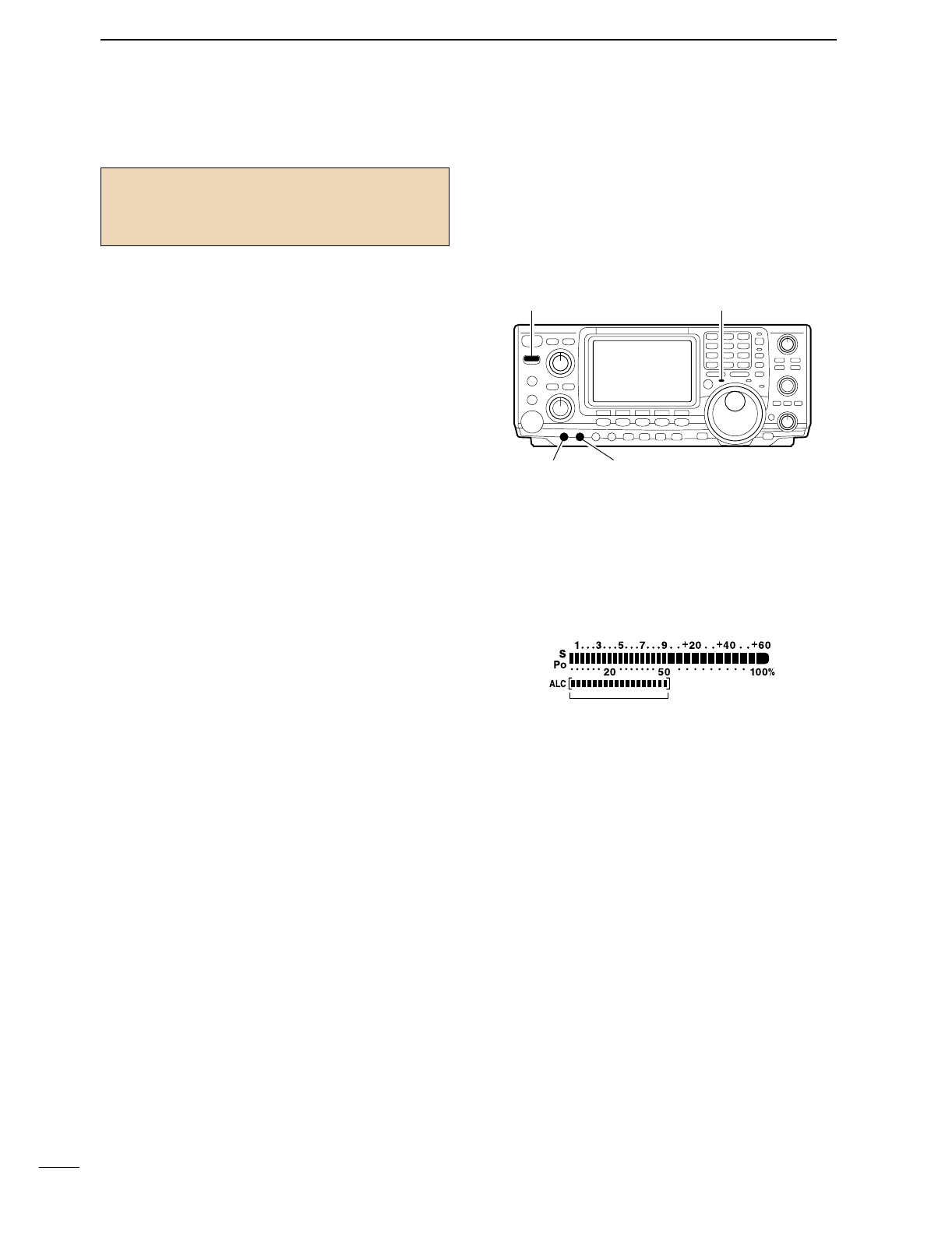
25
3BASIC OPERATION
■Basic transmit operation
DTransmitting
Before transmitting, monitor your selected operating
frequency to make sure transmitting won’t cause inter-
ference to other stations on the same frequency.
qPush [TRANSMIT] or [PTT] (microphone) to trans-
mit.
•The [TX] indicator lights red.
wPush [TRANSMIT] again or release [PTT] (micro-
phone) to return to receive.
DMicrophone gain adjustment
Before transmitting, monitor your selected operating
frequency to make sure transmitting won’t cause inter-
ference to other stations on the same frequency.
qPush [PTT] (microphone) to transmit.
•Talk into the microphone at your normal voice level.
wWhile talking into the microphone, rotate [MIC
GAIN] so that the ALC meter reading doesn’t go
outside the ALC zone (see right).
wRelease [PTT] (microphone) to return to receive.
[TRANSMIT]
[RF PWR][MIC GAIN]
[TX] indicator
ALC zone
Before transmitting, monitor your selected oper-
ating frequency to make sure transmitting won’t
cause interference to other stations on the same
frequency.
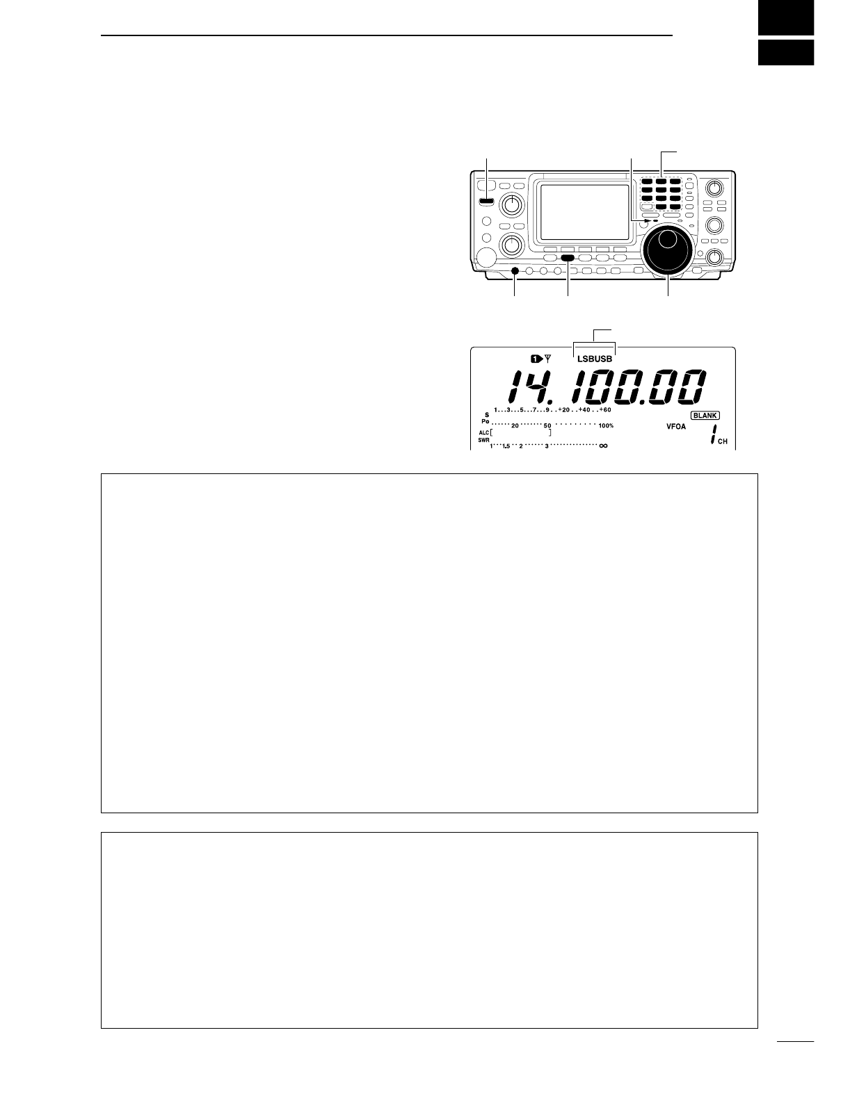
4
26
RECEIVE AND TRANSMIT
■Operating SSB
qPush a band key to select the desired band.
wPush [SSB] to select LSB or USB.
•Below 10 MHz LSB is automatically selected; above
10 MHz USB is automatically selected.
eRotate [AF] to set audio to a comfortable listening
level.
rRotate the tuning dial to tune a desired signal.
•S-meter indicates received signal strength.
tPush [TRANSMIT] or [PTT] (microphone) to trans-
mit.
•The TX indicator lights red.
ySpeak into the microphone at your normal voice
level.
•Adjust [MIC GAIN] at this step, if necessary.
uPush [TRANSMIT] or release [PTT] (microphone) to
return to receive.
Band keys[TX] indicator[TRANSMIT]
[MIC GAIN] [SSB] Tuning dial
“LSB” or “USB” appeare
DConvenient functions for receive
•Preamp and attenuator (p. 48)
➥Push [P.AMP/ATT] several times to set the pre-
amp OFF, preamp 1 ON or preamp 2 ON.
•“P.AMP1,” “P.AMP2” or “P.AMP” appears when the
preamp 1, preamp 2 or preamp is set to ON, respec-
tively. (depending on operating frequency band)
➥Push [P.AMP/ATT] for 1 sec. to set the attenuator
ON.
•Push [P.AMP/ATT] momentarily to turn the attenuator
OFF.
•“ATT” appears when the attenuator is set to ON.
•Noise blanker (p. 51)
➥Push [NB] to turn the noise blanker ON and OFF.
•“NB” appears when the noise blanker is set to ON.
•Push [NB] for 1 sec. to enter noise blanker set mode.
•Noise reduction (p. 53)
➥
Push [NR] to turn the noise reduction ON and OFF.
•Rotate [NR] control to adjust the noise reduction level.
•“NR” appears when the noise reduction is set to ON.
•Auto notch filter (p. 53)
➥Push [A/NOTCH] to turn the auto or manual
notch function ON and OFF.
•Rotate [NOTCH] control to set attenuate frequency for
manual notch operation.
•Twin PBT (passband tuning) (p. 52)
➥Rotate [TWIN PBT] controls (inner/outer).
•Push [PBTC] to clear the settings.
•AGC (auto gain control) (p. 49)
➥While M1 is selected with [MENU], push
[F1 AGC] several times to select AGC F,
AGC M, AGC Sor AGC OFF.
•VSC (voice squelch control) (p. 00)
➥While M2 is selected with [MENU], push
[F5 VSC] to turn the VSC function ON and OFF.
•The VSC indicator appears when the voice squelch
function is set to ON.
DConvenient functions for transmit
•Speech compressor (p. 58)
➥While M1 is selected with [MENU], push [F3
CMP] to turn the speech compressor ON and
OFF.
•“COMP” appears when the speech compressor is set
to ON.
•VOX (voice operated transmit) (p. 54)
➥Push [VOX/BK-IN] to turn the VOX function ON
and OFF.
•“VOX” appears when the VOX function is set to ON.
•Transmit quality monitor (p. 57)
➥Push [MONITOR] to turn the monitor function ON
and OFF.
•“MONI” appears when the monitor function is set to
ON.
•Audio tone control (p. 88)
➥While M2 is selected with [MENU], push [F4
TCN], select an item with [F1 ≤] and [F2 ≥] then
rotate the tuning dial to adjust the audio tone.
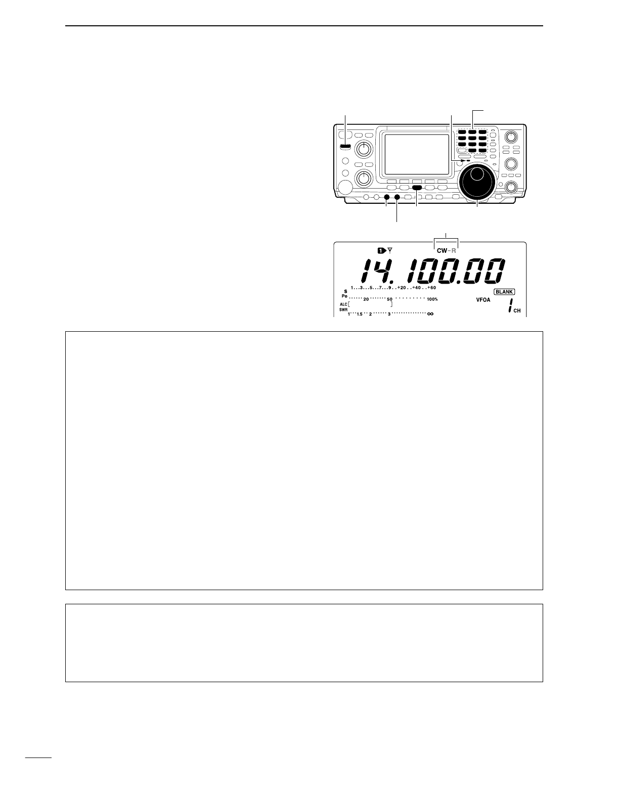
27
4RECEIVE AND TRANSMIT
■Operating CW
qPush a band key to select the desired band.
wPush [CW/RTTY] to select CW.
•After CW mode is selected, push [CW/RTTY] for 1 sec.
to toggle between CW and CW-R modes.
eRotate [AF] to set audio to a comfortable listening
level.
rRotate the tuning dial to simultaneously tune a de-
sired signal and its side tone.
•S-meter indicates received signal strength.
tPush [TRANSMIT] to transmit.
•The TX indicator lights red.
yUse the electric keyer or paddle to key your CW sig-
nals.
•The Po meter indicates transmitted CW signal strength.
uPush [TRANSMIT] to return to receive.
Band keys[TX] indicator[TRANSMIT]
[CW PITCH]
[KEY SPEED]
[CW/RTTY] Tuning dial
“CW” or “CW-R” appeare
DConvenient functions for receive
•Preamp and attenuator (p. 48)
➥Push [P.AMP/ATT] several times to set the pre-
amp OFF, preamp 1 ON or preamp 2 ON.
•“P.AMP1,” “P.AMP2” or “P.AMP” appears when the
preamp 1, preamp 2 or preamp is set to ON, respec-
tively. (depending on operating frequency band)
➥
Push [P.AMP/ATT] for 1 sec. to set the attenuator
ON.
•Push [P.AMP/ATT] momentarily to turn the attenuator
OFF.
•“ATT” appears when the attenuator is set to ON.
•Noise blanker (p. 51)
➥Push [NB] to turn the noise blanker ON and OFF.
•“NB” appears when the noise blanker is set to ON.
•Push [NB] for 1 sec. to enter noise blanker set mode.
•Noise reduction (p. 53)
➥Push [NR] to turn the noise reduction ON and
OFF.
•Rotate [NR] control to adjust the noise reduction level.
•“NR” appears when the noise reduction is set to ON.
•Auto notch filter (p. 53)
➥Push [A/NOTCH] to turn the auto or manual
notch function ON and OFF.
•Rotate [NOTCH] control to set attenuate frequency for
manual notch operation.
•Twin PBT (passband tuning) (p. 52)
➥Rotate [TWIN PBT] controls (inner/outer).
•Push [PBTC] to clear the settings.
•AGC (auto gain control) (p. 49)
➥While M1 is selected with [MENU], push
[F1 AGC] several times to select AGC F,
AGC M, AGC Sor AGC OFF.
•1⁄4function (p. 21)
➥While M1 is selected with [MENU], push
[F3 1/4] to turn the 1⁄4function ON and OFF.
DConvenient functions for transmit
•Break-in function (p. 56)
➥Push [VOX/BK-IN] several times to set the break-
in OFF, semi break-in or full break-in.
•“BK-IN” or “FBK-IN” appears when the semi break-in
or full break-in is set to ON, respectively.
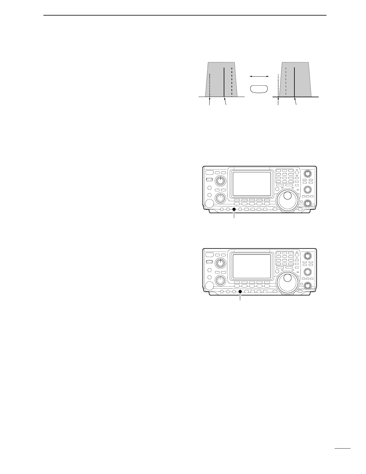
28
4
RECEIVE AND TRANSMIT
DAbout CW reverse mode
CW reverse mode receives CW signals with a reverse
side CW carrier point like that of LSB and USB modes.
Use this mode when interfering signals are near the
desired signal and you want to change the interference
tone.
Use when interfering signals are near a desired signal
and you want to change the interference tone.
qPush [CW/RTTY] several times to select CW mode.
wPush [CW/RTTY] for 1 sec. to select CW or CW-R
mode.
•Check the interfering tone.
DAbout CW pitch control
The received CW audio pitch and monitored CW audio
can be adjusted to suit your preference (300 to 900 Hz
in 25 Hz steps) without changing the operating fre-
quency.
DAbout keying speed
The transceiver’s internal electronic keyer speed can
be adjusted from 6 to 60 wpm.
➥Rotate [KEY SPEED] clockwise to increase keying
speed; counterclockwise to decrease keying speed.
DCW side tone function
When the transceiver is in the receive condition (and
the break-in function is OFF— p. 56) you can listen to
the tone of your CW signal without actually transmit-
ting. This allows you to match your transmit signal ex-
actly to another station’s. This also convenient for CW
practice. CW side tone level can be adjusted in keyer
set mode (p. 33).
Push for 1 sec.
BFO
CW-R mode (USB side)
BFO
Desired signal
CW mode (LSB side)
Interference Desired signalInterference
CW/RTTY
[CW PITCH]
[KEY SPEED]
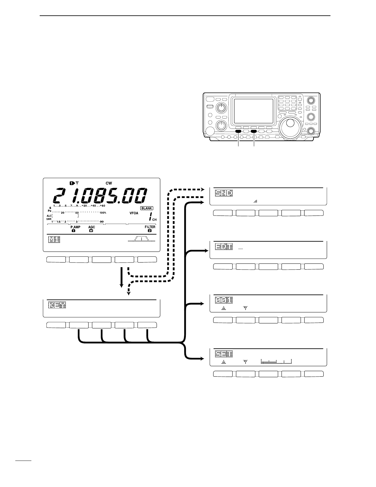
29
4RECEIVE AND TRANSMIT
■Electronic keyer functions
The transceiver has a number of convenient functions
for the electronic keyer that can be accessed from the
memory keyer menu.
qPush [CW/RTTY] to select CW mode.
wPush [MENU] to select M1.
ePush [F4 KEY] to select the memory keyer menu.
•The selectable menu can be changed with the keyer
send menu in the set mode. (p. 86)
rPush one of the multi-function keys ([F1] to [F5]) to
select an item in the memory keyer menu. See the
diagram below.
•Push [MENU] to return to the previous indication.
DIN CW MODE
F
1F
2F
3F
4F
5
F
1F
2F
3F
4F
5
F
1F
2F
3F
4F
5
F
1F
2F
3F
4F
5
F
1F
2F
3F
4F
5
F
1F
2F
3F
4F
5
AGC
DUP
1/4
KEY
SCP
M1
M2
M3
M4
-1
5O%1
Side
Tone
Level
Normal1
Number
Style
CQ
TEST
CQ
TEST
M1
ç
å
DEL
SPC
Push [F4]
Push [MENU] Push
[F4]
Push
[F2]
Push
[F3]
Push
[F5]
• Keyer send menu (p. 40)
SND
EDT
001
SET
• Memory keyer menu
• Keyer set mode (p. 33)
• Contest number set mode (p. 32)
• Edit menu (p. 31)
[MENU] [CW/RTTY]
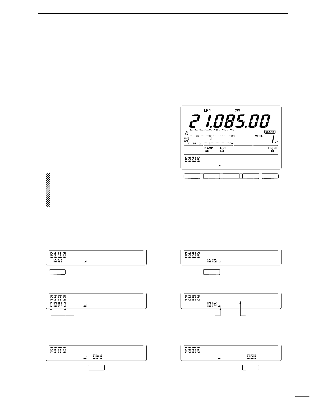
30
4
RECEIVE AND TRANSMIT
F 1
F
2F
3
F
4
F
5
F
2
F 1
F
4
F
3
Repeat indicators Count up trigger
indicator
Counter
M1
M2
M3
M4
-1
M1
M2
M3
M4
-1
M2 send indication
M1
M2
M3
M4
-1
CQ
TEST
CQ
001
CQ
TEST
CQ
001
QRZ?
M1
M2
M3
M4
-1
UR
5NN001
B
001
001
M1
M2
M3
M4
-1
UR
5NN001
B
001
CFM
TU
001
M1 send indication
M2 send indicationRepeat send indication
M1
M2
M3
M4
-1
M4 send indication
M1
M2
M3
M4
-1
M3 send indication
DMemory keyer send menu
Pre-set characters can be sent using the keyer send
menu. Contents of the memory keyer are set using the
edit menu.
•Transmitting
qWhile M1 is selected in CW mode, push [F4 KEY]
to select the memory keyer menu.
wPush [F2 SND] to select the keyer send menu.
ePush [TRANSMIT] to set the transceiver to trans-
mit, or set the break-in function ON (p. 56).
rPush one of the function keys ([F1] to [F4]) to send
the contents of the memory keyer.
•Pushing a function key for 1 sec. repeatedly sends the
contents; push any function key to cancel the transmis-
sion.
•The contest number counter, above [F5], is incremented
each time the contents are sent.
•Push [F5] to reduce the contact number count by 1 when
resending contents to unanswered calls.
For your information
When an external keypad is connected to the
pin 3 and pin 7 of the [MIC] connector, the pro-
grammed contents, M1—M4, can be transmitted
without selecting the keyer send menu.
See p. 86 for details.
rPush [MENU] 2 times to return to M1.
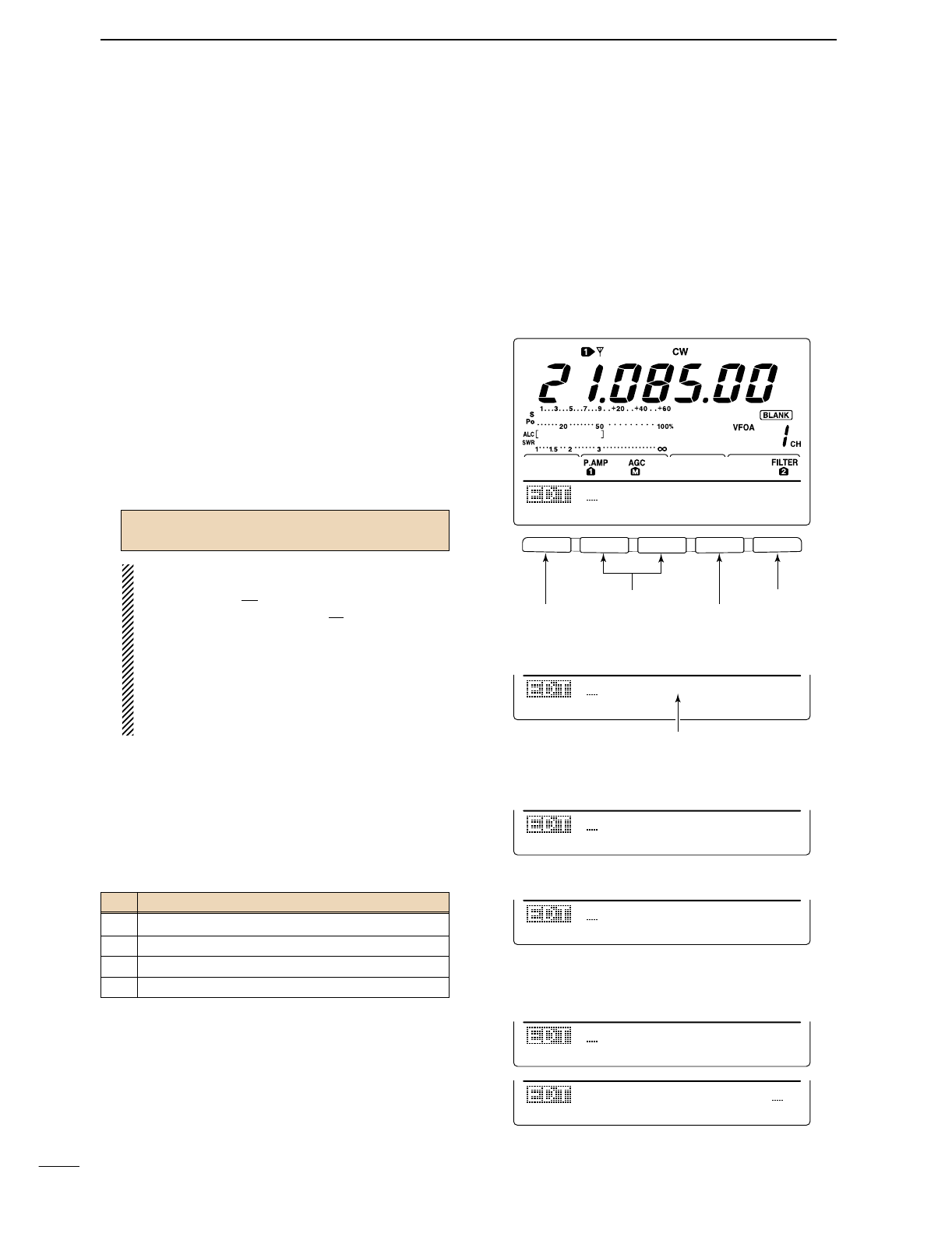
31
4RECEIVE AND TRANSMIT
DEditing a memory keyer
The contents of the memory keyer memories can be
set using the memory keyer edit menu. The memory
keyer can memorize and re-transmit 4 CW key codes
for often-used CW sentences, contact numbers, etc.
Total capacity of the memory keyer is 50 characters
per memory channel.
•Programming contents
qPush [MENU] to select M1, then push [F4 KEY] to
select the memory keyer menu.
wPush [F3 EDIT] to select edit menu.
•Memory keyer contents of the channel 1 (M1) is indi-
cated.
•Push [F5] to manually increment the contest number.
ePush [F1] to select the desired memory keyer chan-
nel to be edited.
rInput the desired character by rotating the tuning
dial or by pushing the keypad for number input.
•Selectable characters (with the tuning dial);
NOTE:
“^” is used to transmit a following word with no
space such as
AR
. Put “^” before a text string
such as ^AR, and the string “
AR
” is sent with no
space.
“*” is used to insert the CW contact number. The
contact number automatically increments by 1.
This function is only available for one memory
keyer channel at a time. Memory keyer channel
M2 used “*” by default.
tPush [F2 ç] or [F3 å] to move the cursor back-
wards or forwards, respectively.
yRepeat steps rand tto input the desired charac-
ters.
uPush [MENU] 2 times to return to M1.
Pre-programmed contents
A B C D E F G H I J K L M N O P Q R S T
U V W X Y Z / ? . , * ^
CH Contents
M1 CQ TEST CQ TEST DE JA1 JA1 TEST
M2 UR 5NN* BK
M3 CFM TU
M4 QRZ?
F 1
F
2F
3
F
4
F
5
CQ
TEST
CQ
TEST
M1
ç
å
DEL
SPC
UR
5NN*
BK
M2
ç
å
DEL
SPC
• Edit menu
• M2 default indication
CFM
TU
M3
ç
å
DEL
SPC
• M3 default indication
QSL
TU
DE
JA3Y
M3
ç
å
DEL
SPC
DE
JA3YUA
TEST
M3
ç
å
DEL
SPC
Example display— when inputting “QSL TU
DE JA3YUA TEST” into M3.
QRZ?
M4
ç
å
DEL
SPC
• M4 default indication
Select M1 to M4
Move cursor left/right
Clear character
Input space
When inputting an astarisk,
the counter is incremented by 1.
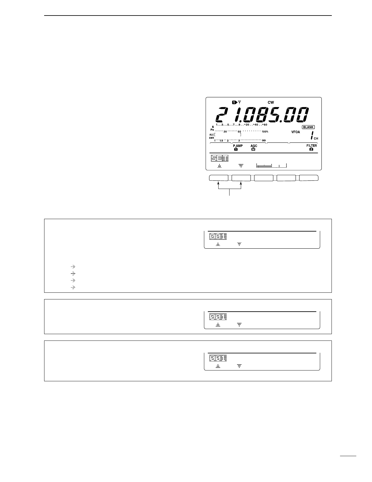
32
4
RECEIVE AND TRANSMIT
DContest number set mode
This menu is used to set the contest (serial) number
and count up trigger, etc.
•Setting contents
qPush [MENU] to select M1, then push [F4 KEY] to
select the memory keyer menu.
wPush [F4 001] to enter the contest number set
mode.
ePush [F1≤] or [F2 ≥] to select the desired set item.
rSet the desired condition using the tuning dial.
•Push [F3] for 1 sec. to select a default condition or value.
tPush [MENU] 2 times to return to M1.
F 1
F
2F
3
F
4
F
5
1
Set item up/down
5O%
Side
Tone
Level
2. Count Up Trig
This item sets the count up trigger channel.
•M1, M2, M3 and M4 can be set. (default: M2)
M22
Count
Up
Trig
1. Number Style
This item sets the numbering system used for contact
(serial) numbers— normal or morse cut numbers.
•Normal : Does not use morse cut number
(default)
•190 ANO : Sets 1 as A, 9 as N and 0 as O.
•190 ANT : Sets 1 as A, 9 as N and 0 as T.
•90 NO : Sets 9 as N and 0 as O.
•90 NT : Sets 9 as N and 0 as T.
Normal1
Number
Style
3. Present Number
This item shows the current number for the count up
trigger channel set above.
•Rotate the tuning dial to change the number, or push
[F3 CLR] for 1 sec. to reset the current number to 001.
CLR
0013
Present
Number
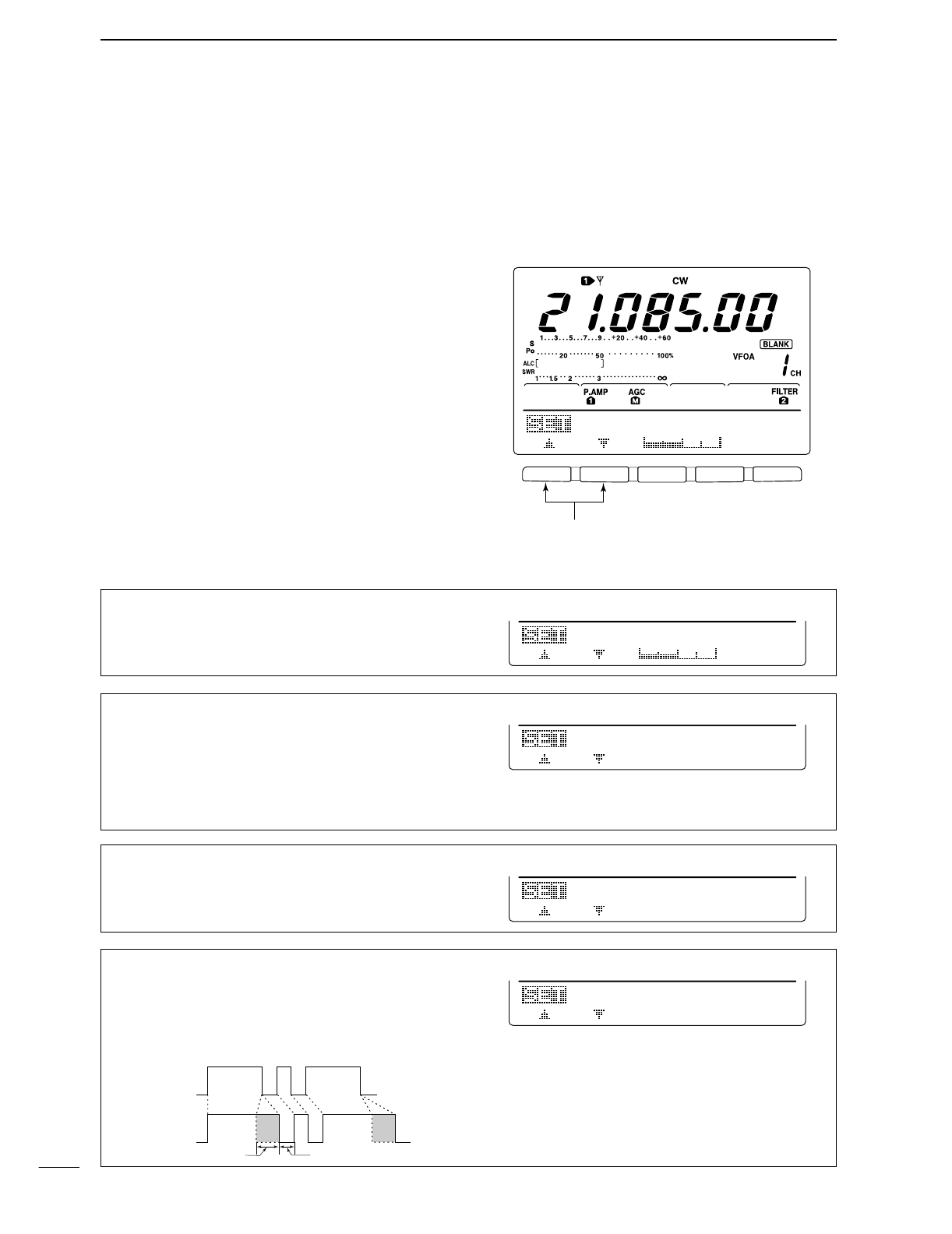
33
4RECEIVE AND TRANSMIT
DKeyer set mode
This set mode is used to set the CW side tone, mem-
ory keyer repeat time, dash weight, paddle specifica-
tions, keyer type, etc.
•Setting contents
qPush [MENU] to select M1, then push [F4 KEY] to
select the memory keyer menu.
wPush [F5 SET] to select keyer set mode.
ePush [F1≤] or [F2 ≥] to select the desired set item.
rSet the desired condition using the tuning dial.
•Push [F3] for 1 sec. to select a default condition or value.
tPush [MENU] 2 times to return to M1.
F 1
F
2F
3
F
4
F
5
1
Set item up/down
5O%
Side
Tone
Level
1. Side Tone Level
This item sets the CW side tone output level.
•0 to 100% in 1% step can be selected.
5O%1
Side
Tone
Level
2. Side Tone L-lmt
This item sets the CW side tone level limit. When the
[AF] control is rotated above a specified level, the CW
side tone does not increase.
ON CW side tone level is limited. (default)
OFF CW side tone level is not limited.
ON2
Side
Tone
L-lmt
3. Repeat Time
When sending CW using the repeat timer, this item
sets the time between transmission.
•1 to 60 sec. in 1 sec. step can be selected.
2s3
Repeat
Time
4. Dot/Dash Ratio
This item sets the dot/dash ratio.
•1:1:2.8 to 1:1:4.5 (in 0.12 step) can be selected.
Keying weight example: Morse code “K”
1:1:3.O4
Dot/Dash
Ratio
DASH
Weight setting:
1:1:3 (default)
Weight setting:
Adjusted
DASH
DOT (fixed*)
Adjustable range SPACE (fixed*)
*SPACE and DOT length can be
adjusted with [KEY SPEED] only.
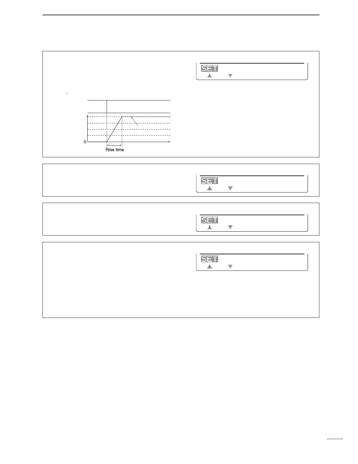
34
4
RECEIVE AND TRANSMIT
5. Rise Time
This item set the envelop time period which the output
power becomes the set transmit power.
•2, 4, 6 or 8 msec. can be selected.
4ms5
Rise
Time
Key action
Tx output power
• About rise time
Tx
Rx
Set Tx power level
Time
6. Paddle Polarity
This item sets the paddle polarity.
•Normal and reverse polarity can be selected.
NORMAL6
Paddle
Polarity
7. Keyer Type
This item selects the keyer type for [ELEC-KEY] con-
nector on the front panel.
•ELEC-KEY, BUG KEY and Straight key can be selected.
ELEC-KEY7
Keyer
Type
8. MIC U/D Keyer
This item allow you to set the microphone [UP]/[DN]
keys to be used as a paddle.
ON [UP]/[DN] switches can be used for CW.
OFF [UP]/[DN] switches cannot be used for
CW.
NOTE: When “ON” is selected, the frequency and
memory channel cannot be changed using
the [UP]/[DN] switches.
OFF8
MIC
U/D
Keyer
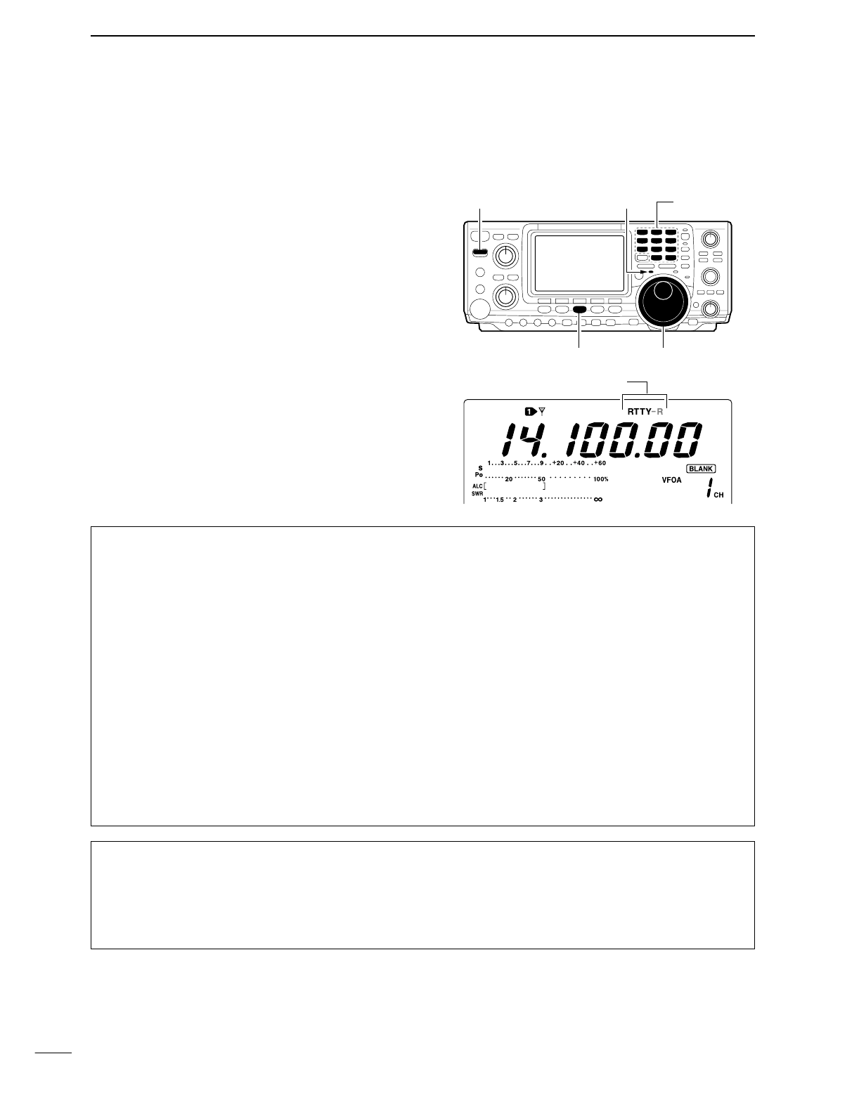
35
4RECEIVE AND TRANSMIT
■Operating RTTY (FSK)
Before operating RTTY, be sure to consult the manual
that come with your TNC.
qPush a band key to select the desired band.
wPush [CW/RTTY] several times to select RTTY.
•After RTTY mode is selected, push [CW/RTTY] for
1 sec. to toggle RTTY and RTTY-R modes.
eRotate [AF] to set audio to a comfortable listening
level.
rRotate the tuning dial to tune a desired signal.
•S-meter indicates received signal strength.
•If the received signal cannot be demodulated, try select-
ing RTTY-R mode.
tPush [TRANSMIT] to set the transceiver to the
transmit condition or transmit a SEND signal from
your TNC.
•The TX indicator lights red.
•
The Po meter indicates transmitted RTTY signal strength.
yOperate the connected PC or TNC (TU) to transmit
RTTY (FSK) signals.
•Adjust [MIC GAIN] at this step, if necessary.
uPush [TRANSMIT] to return to receive.
Band keys[TX] indicator[TRANSMIT]
[CW/RTTY] Tuning dial
“RTTY” or “RTTY-R” appeared
DConvenient functions for receive
•Preamp and attenuator (p. 48)
➥Push [P.AMP/ATT] several times to set the pre-
amp OFF, preamp 1 ON or preamp 2 ON.
•“P.AMP1,” “P.AMP2” or “P.AMP” appears when the
preamp 1, preamp 2 or preamp is set to ON, respec-
tively. (depending on operating frequency band)
➥Push [P.AMP/ATT] for 1 sec. to set the attenuator
ON.
•Push [P.AMP/ATT] momentarily to turn the attenuator
OFF.
•“ATT” appears when the attenuator is set to ON.
•Noise blanker (p. 51)
➥Push [NB] to turn the noise blanker ON and OFF.
•“NB” appears when the noise blanker is set to ON.
•Push [NB] for 1 sec. to enter noise blanker set mode.
•Noise reduction (p. 53)
➥Push [NR] to turn the noise reduction ON and
OFF.
•Rotate [NR] control to adjust the noise reduction level.
•“NR” appears when the noise reduction is set to ON.
•Twin PBT (passband tuning) (p. 52)
➥Rotate [TWIN PBT] controls (inner/outer).
•Push [PBT C] to clear the settings.
•AGC (auto gain control) (p. 49)
➥While M1 is selected with [MENU], push
[F1 AGC] several times to select AGC F,
AGC M, AGC Sor AGC OFF.
•1⁄4function (p. 21)
➥While M1 is selected with [MENU], push
[F3 1/4] to turn the 1⁄4function ON and OFF.
DConvenient functions for transmit
•Transmit quality monitor (p. 57)
➥Push [MONITOR] to turn the monitor function ON
and OFF.
•“MONI” appears when the monitor function is set to
ON.
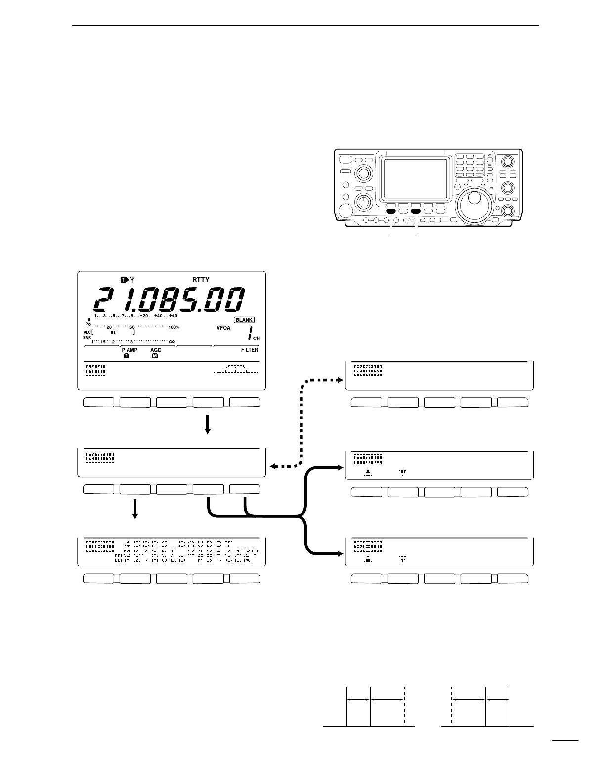
36
4
RECEIVE AND TRANSMIT
■RTTY functions
The transceiver has a number of convenient functions
for the RTTY operation that can be accessed from the
RTTY menu.
qPush [CW/RTTY] to select RTTY mode.
wPush [MENU] to select M1.
ePush [F4 RTY] to select the RTTY menu.
rPush one of the multi-function keys ([F2], [F4] or
[F5]) to select an item in the RTTY menu. See the
diagram below.
•Push [MENU] to return to the previous indication.
DIN RTTY MODE
F 1 F 2 F 3 F 4 F 5
F 1 F 2 F 3 F 4 F 5
F 1 F 2 F 3 F 4 F 5
F 1 F 2 F 3 F 4 F 5
F 1 F 2 F 3 F 4 F 5
F 1 F 2 F 3 F 4 F 5
AGC
DUP
1/4
RTY
SCP
DEC
FIL
SET
21251
RTTY
Mark
35O1
Band
Width
ADJ
RTTY-FIL
ON
DEC
FIL
SET
• RTTY menu
• RTTY decoder screen (p. 38)
• RTTY filter set mode (p. 37)
• RTTY set mode (p. 39)
Push [F4]
Push
[F4] for
1 sec.
Switches RTTY filter ON and OFF.
Push
[F4]
Push
[F5]
Push [F2]
[MENU] [CW/RTTY]
DAbout RTTY reverse mode
Received characters are occasionally garbled when
the receive signal is reversed between MARK and
Space. This reversal can be caused by incorrect TNC
connections, setting, commands, etc. To receive re-
versed RTTY signal correctly, select RTTY-R mode.
➥While RTTY mode is selected, push [CW/RTTY]
for 1 sec. to select the RTTY reverse mode.
•“RTTY-R” appears when the RTTY reverse mode is se-
lected.
•Push [CW/RTTY] for 1 sec. again to select the normal
RTTY mode.
Normal Reverse
170
Hz
170
Hz
2125
Hz
2125
Hz
BFOBFO Space
Space Mark
Mark
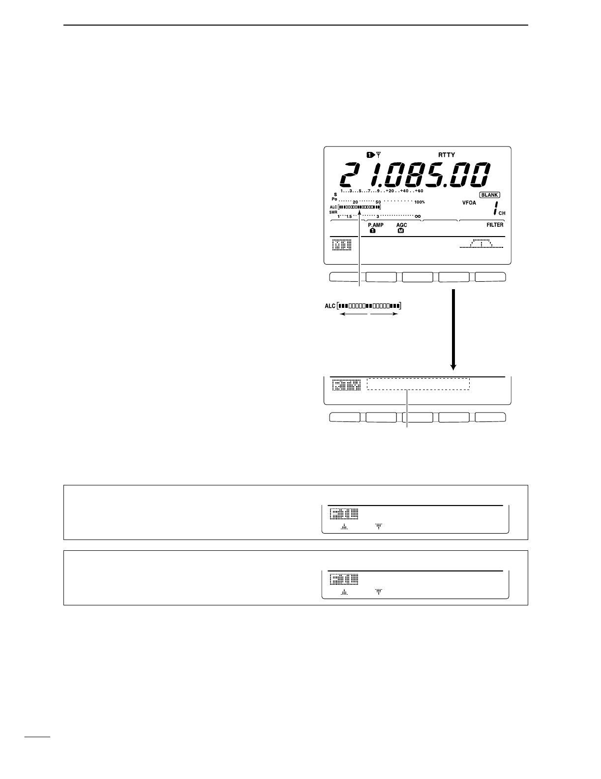
DRTTY filter/Twin peak filter
The transceiver has 5 RTTY filters in addition to nor-
mal IF filters. The passband width can be selected
from 1 kHz, 500 Hz, 350 Hz, 300 Hz and 250 Hz.
When the RTTY filter is turned ON, the RTTY tuning
meter can be used.
Moreover, the twin peak filter changes the receive fre-
quency response by boosting 2 particular frequencies
(2125 and 2295 Hz) for better copying of desired
RTTY signals.
•RTTY filter and twin peak filter setting
qPush [CW/RTTY] to select RTTY mode.
•After RTTY mode is selected, push [CW/RTTY] for 1 sec.
to select RTTY-R mode.
wPush [MENU] several times to select M1.
ePush [F4 RTY] to select RTTY menu.
rPush [F4 FIL] to turn the RTTY filter ON and OFF.
•When the RTTY filter is turned ON, the normal IF filter
number indication (1, 2or 3) disappear.
tPush [F4 FIL] for 1 sec. to enter RTTY filter set
mode (see below).
yPush [F1≤] to select bandwidth item.
uRotate the tuning dial to select the RTTY filter width
from 1 kHz, 500 Hz, 350 Hz, 300 Hz and 250 Hz.
•Push [F3] for 1 sec. to select a default value.
iPush [F2 ≥] to select twin peak filter item.
•The received audio volume may become greater when
the twin peak filter is turned ON.
oRotate the tuning dial to turn the twin peak filter
function ON and OFF.
!0 Push [MENU] 2 times to return to M1.
•RTTY filter set mode
37
4RECEIVE AND TRANSMIT
F1
F2 F3 F4 F5
F1
F2 F3 F4 F5
AGC
DUP
1/4
RTY
SCP
DEC
FIL
SET
RTTY-FIL
ON
Push [F4]
Disappears when the RTTY
filter is turned OFF.
RTTY filter indicator
Rotate the tuning dial at the
point where the both sides of
dots are appeared equality.
1. Band Width
This item sets the RTTY filter width.
•250, 300, 350, 500 Hz and 1 kHz can be selected.
35O1
Band
Width
2. Twin Peak FIL
This item turn the twin peak filter ON and OFF.
ON2
Twin
Peak
FIL
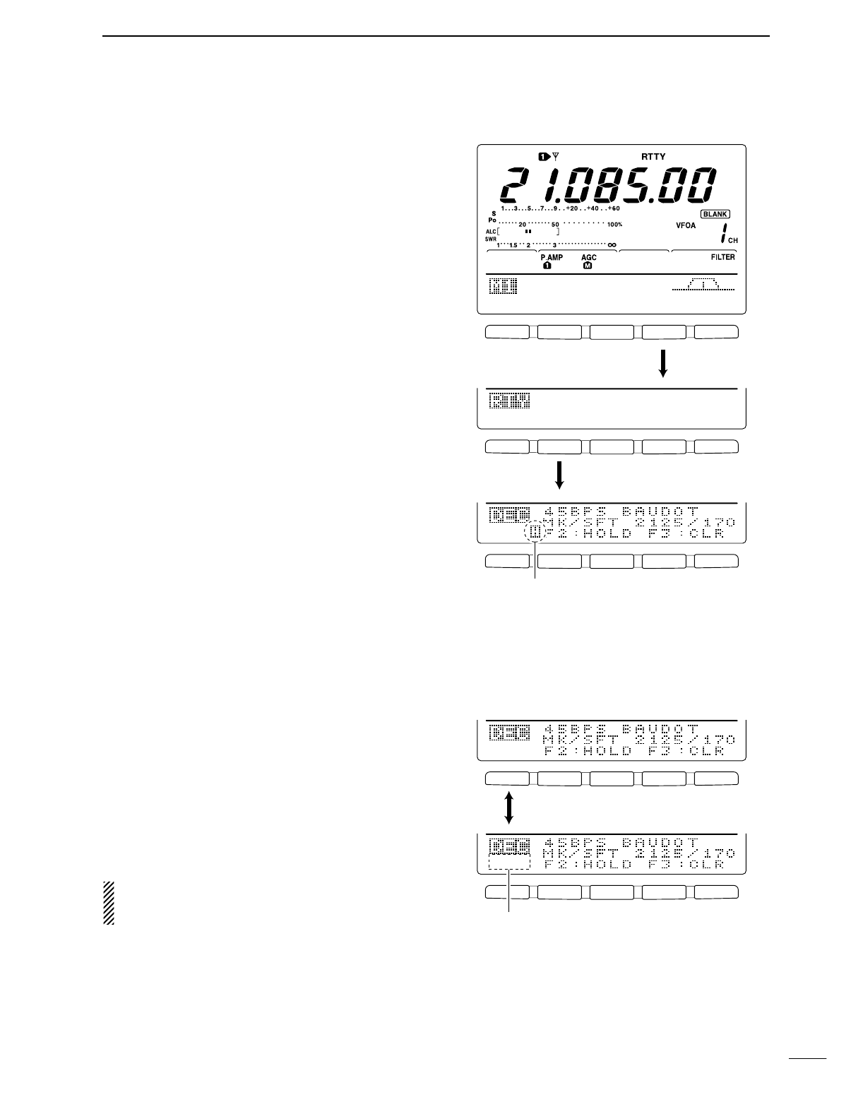
38
4
RECEIVE AND TRANSMIT
F 1 F 2 F 3 F 4 F 5
F 1 F 2 F 3 F 4 F 5
F 1 F 2 F 3 F 4 F 5
AGC
DUP
1/4
RTY
SCP
DEC
FIL
SET
ADJ
RTTY-FIL
ON
Push [F4]
Push [F2]
Appears while the RTTY decoder screen is freezed
with [F2] operation.
Push [F3] to erase the displayed characters.
DRTTY decoder
The transceiver has an RTTY decoder for Baudot
(mark freq.: 2125 Hz, shift freq.: 170 Hz, 45 bps).
An external terminal unit (TU) or terminal node con-
nector (TNC) is not necessary for receiving a Baudot
signal.
qPush [CW/RTTY] to select RTTY mode.
•After RTTY mode is selected, push [CW/RTTY] for 1 sec.
to select RTTY-R mode.
wPush [MENU] several times to select M1.
ePush [F4 RTY] to select RTTY menu.
rPush [F4 FIL] to turn the RTTY filter ON.
•The RTTY decoder does not function when the RTTY fil-
ter is turned OFF.
tPush [F2 DEC] to turn the RTTY decoder ON.
•RTTY decoder screen appears.
yPush [F2] to freeze the current screen.
•“H” appears while the function is in use.
uPush [F3] for 1 sec. to clear the displayed charac-
ters.
iPush [MENU] to exit the RTTY decoder screen.
•Setting the decoder threshold level
Adjust the RTTY decoder threshold level if some char-
acters are displayed when no signal is received.
qCall up the RTTY decoder screen as described at
above.
wPush [F1 ADJ] to select the threshold level setting
condition.
eRotate the tuning dial to adjust the RTTY decoder
threshold level.
•Push [F3] for 1 sec. to select the default condition.
rPush [MENU] to exit the RTTY decoder screen.
A number of indicating line, the UnShift On Space
(USOS) function and new line code can be set in
the RTTY set mode. (p. 39)
F 1 F 2 F 3 F 4 F 5
F 1 F 2 F 3 F 4 F 5
ADJ
å
9
Push [F1]
Threshold level indication
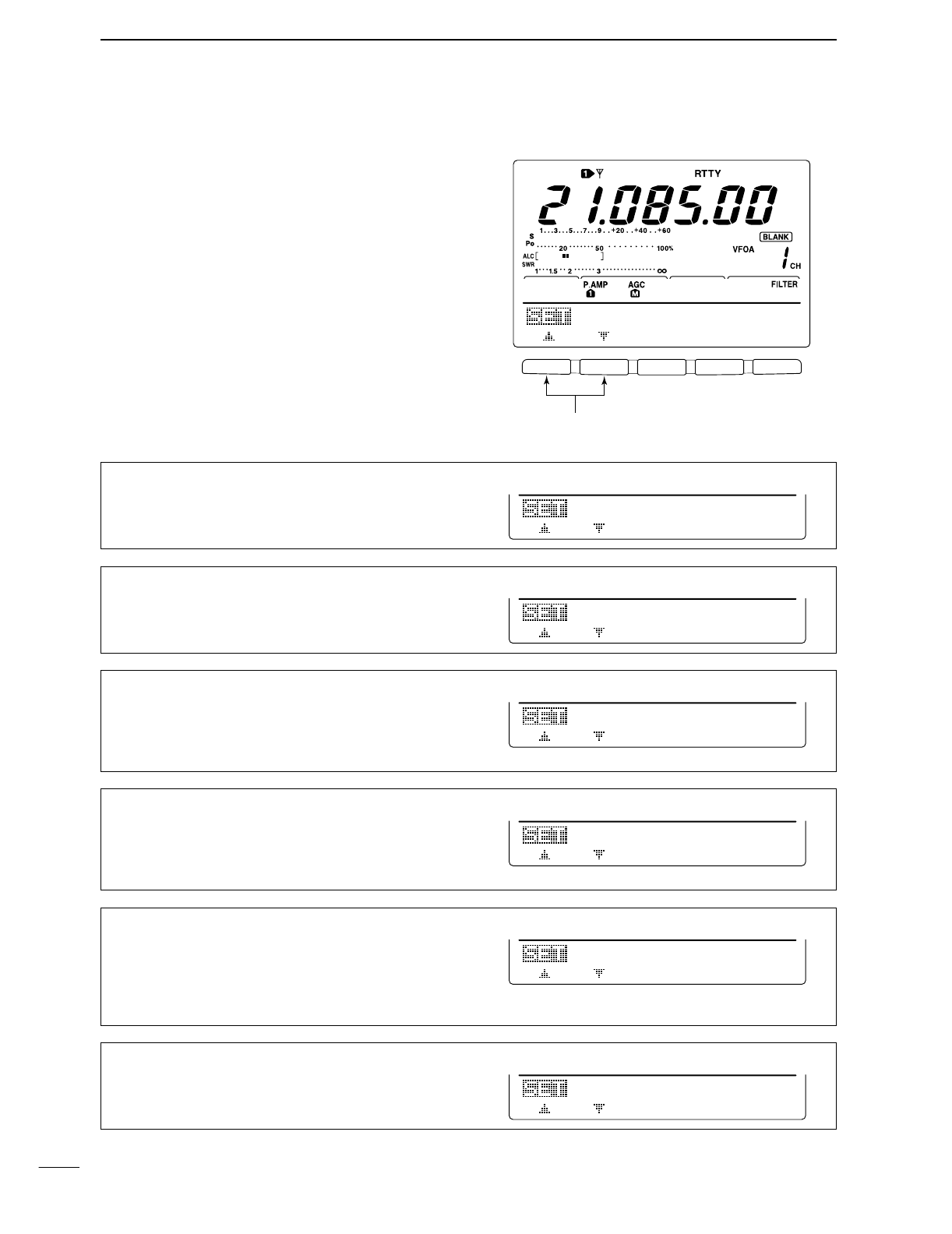
39
4RECEIVE AND TRANSMIT
DRTTY set mode
This set mode is used to set the mark and shift fre-
quencies, keying type, decode USOS function, etc.
•Setting contents
qPush [MENU] to select M1, then push [F4 RTY] to
select the RTTY menu.
wPush [F5 SET] to select RTTY set mode.
ePush [F1≤] or [F2 ≥] to select the desired set item.
rSet the desired condition using the tuning dial.
•Push [F3] for 1 sec. to select a default condition or value.
tPush [MENU] 2 times to return to M1.
F 1 F 2 F 3 F 4 F 5
21251
RTTY
Mark
Set item up/down
1. RTTY Mark
Sets the mark frequency for RTTY operation.
•1275, 1615 and 2125 Hz are selectable.
21251
RTTY
Mark
2. RTTY Shift
Sets the shift frequency for RTTY operation.
•170, 200 and 425 Hz are selectable.
17O2
RTTY
Shift
3. RTTY Keying
Selects the keying polarity from normal and reverse.
NORMAL Key open/close = Mark/Space
REVERSE Key open/close = Space/Mark
NORMAL
3
RTTY
Keying
4. Decode USOS
Turn the USOS (UnShift On Space) function ON/OFF
ON Decode as letter code
OFF Decode as character code
ON
4
Decode
USOS
5. Decode New Line
Selects the new line code of the internal RTTY decoder.
CR: Carriage Return; LF: Line Feed
CR,LF,CR+LF CR, LF and CR+LF
CR+LF CR+LF only
CR,LF,CR+LF
5
Decode
New
Line
6. Decode Screen
Selects a number of the decoder indication from 2 line
and 3 line.
3line
6
Decode
Screen
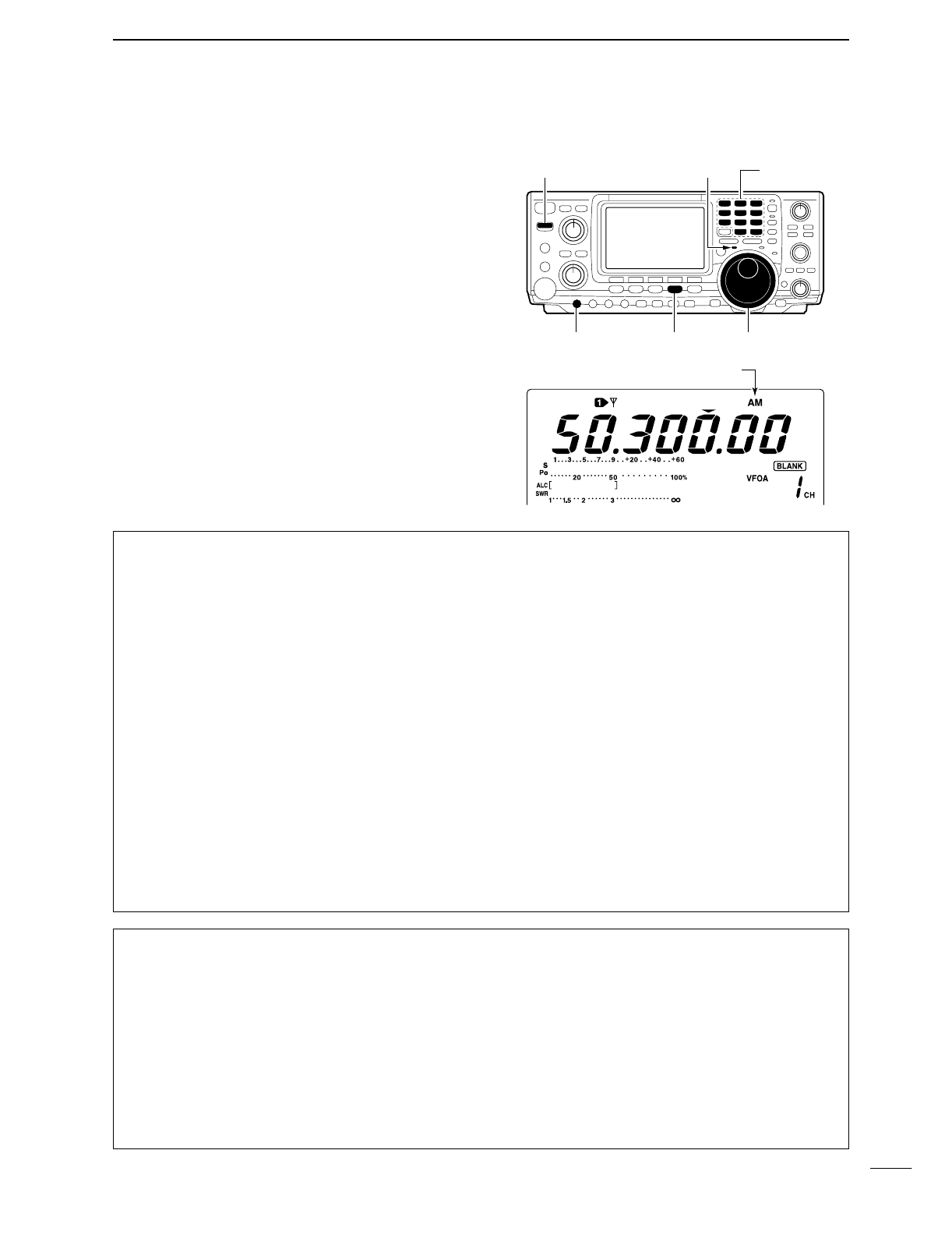
40
4
RECEIVE AND TRANSMIT
■Operating AM
qPush a band key to select the desired band.
wPush [AM/FM] to select AM.
eRotate [AF] to set audio to a comfortable listening
level.
rRotate the tuning dial to tune a desired signal.
•S-meter indicates received signal strength.
•The default tuning step for AM mode is 1 kHz; this can
be changed using tuning step program mode. (p. 21)
tPush [TRANSMIT] or [PTT] (microphone) to trans-
mit.
•The TX indicator lights red.
ySpeak into the microphone at your normal voice
level.
•Adjust [MIC GAIN] at this step, if necessary.
uPush [TRANSMIT] or release [PTT] (microphone) to
return to receive.
Band keys[TX] indicator[TRANSMIT]
[MIC GAIN] [AM/FM] Tuning dial
Appears
DConvenient functions for receive
•Preamp and attenuator (p. 48)
➥Push [P.AMP/ATT] several times to set the pre-
amp OFF, preamp 1 ON or preamp 2 ON.
•“P.AMP1,” “P.AMP2” or “P.AMP” appears when the
preamp 1, preamp 2 or preamp is set to ON, respec-
tively. (depending on operating frequency band)
➥Push [P.AMP/ATT] for 1 sec. to set the attenuator
ON.
•Push [[p.AMP/ATT] momentarily to turn the attenuator
OFF.
•“ATT” appears when the attenuator is set to ON.
•Noise blanker (p. 51)
➥Push [NB] to turn the noise blanker ON and OFF.
•“NB” appears when the noise blanker is set to ON.
•Push [NB] for 1 sec. to enter noise blanker set mode.
•Noise reduction (p. 53)
➥
Push [NR] to turn the noise reduction ON and OFF.
•Rotate [NR] control to adjust the noise reduction level.
•“NR” appears when the noise reduction is set to ON.
•Auto notch filter (p. 53)
➥Push [A/NOTCH] to turn the auto or manual
notch filter ON and OFF.
•Rotate [NOTCH] control to set attenuate frequency for
manual notch operation.
•IF shift (p. 52)
➥Rotate [TWIN PBT] controls (inner only).
•Push [PBTC] to clear the settings.
•AGC (auto gain control) (p. 49)
➥While M1 is selected with [MENU], push [F1
AGC] several times to select AGC F, AGC M,
AGC Sor AGC OFF.
•VSC (voice squelch control) (p. 00)
➥While M2 is selected with [MENU], push
[F5 VSC] to turn the VSC function ON and OFF.
•The VSC indicator appears when the voice squelch
function is set to ON.
DConvenient functions for transmit
•Speech compressor (p. 58)
➥While M1 is selected with [MENU], push [F3
CMP] to turn the speech compressor ON and
OFF.
•“COMP” appears when the speech compressor is set
to ON.
•VOX (voice operated transmit) (p. 54)
➥Push [VOX/BK-IN] to turn the VOX function ON
and OFF.
•“VOX” appears when the VOX function is set to ON.
•Transmit quality monitor (p. 57)
➥Push [MONITOR] to turn the monitor function ON
and OFF.
•“MONI” appears when the monitor function is set to
ON.
•Audio tone control (p. 88)
➥While M2 is selected with [MENU], push [F4
TCN], select an item with [F1 ≤] and [F2 ≥] then
rotate the tuning dial to adjust the audio tone.
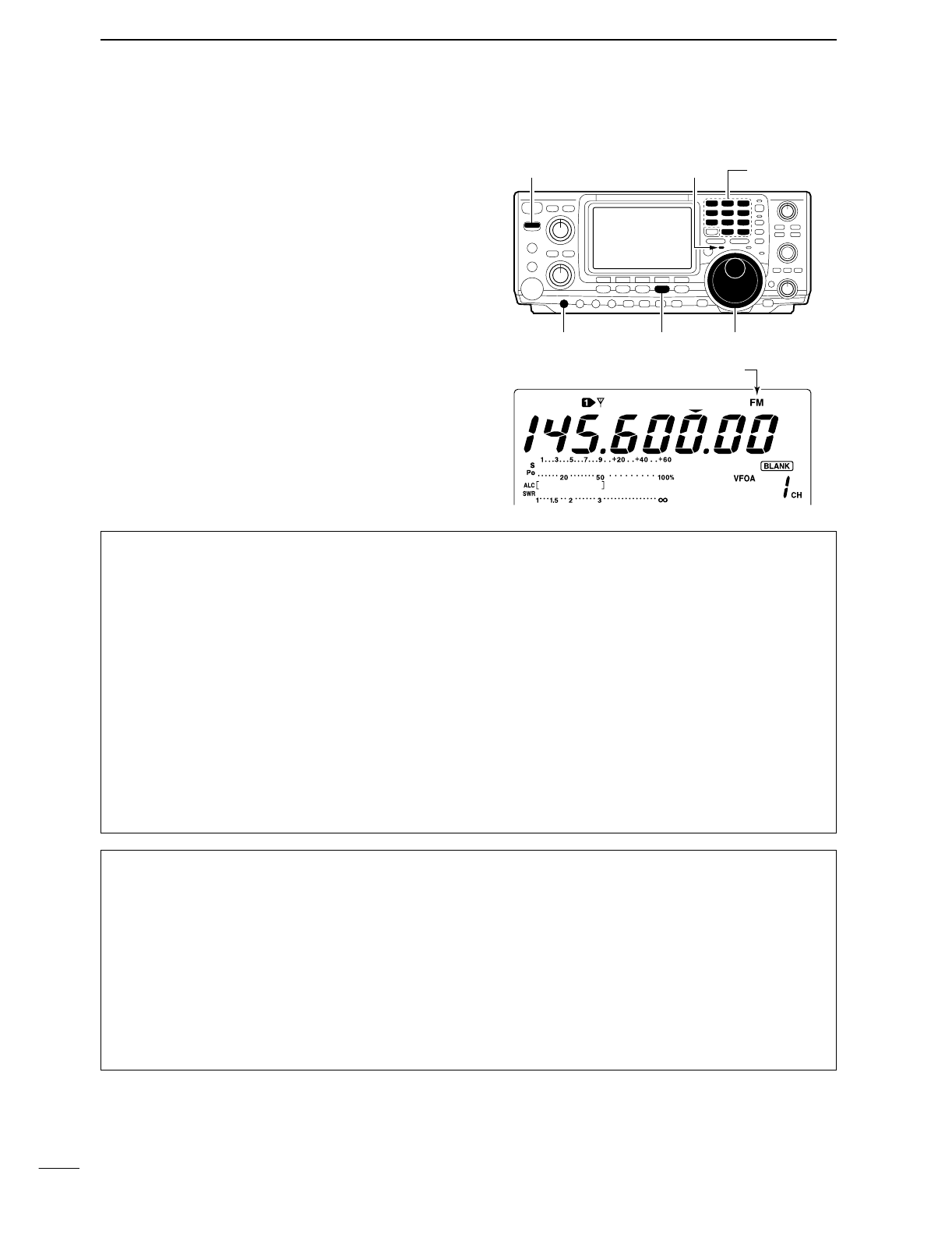
41
4RECEIVE AND TRANSMIT
■Operating FM
qPush a band key to select the desired band.
wPush [AM/FM] to select FM.
eRotate [AF] to set audio to a comfortable listening
level.
rRotate the tuning dial to tune a desired signal.
•S-meter indicates received signal strength.
tPush [TRANSMIT] or [PTT] (microphone) to trans-
mit.
•The TX indicator lights red.
ySpeak into the microphone at your normal voice
level.
•Adjust [MIC GAIN] at this step, if necessary.
uPush [TRANSMIT] or release [PTT] (microphone) to
return to receive.
Band keys[TX] indicator[TRANSMIT]
[MIC GAIN] [AM/FM] Tuning dial
Appear
DConvenient functions for receive
•Preamp and attenuator (p. 48)
➥Push [P.AMP/ATT] several times to set the pre-
amp OFF, preamp 1 ON or preamp 2 ON.
•“P.AMP1,” “P.AMP2” or “P.AMP” appears when the
preamp 1, preamp 2 or preamp is set to ON, respec-
tively. (depending on operating frequency band)
➥Push [P.AMP/ATT] for 1 sec. to set the attenuator
ON.
•Push [[p.AMP/ATT] momentarily to turn the attenuator
OFF.
•“ATT” appears when the attenuator is set to ON.
•Noise blanker (p. 51)
➥Push [NB] to turn the noise blanker ON and OFF.
•“NB” appears when the noise blanker is set to ON.
•Push [NB] for 1 sec. to enter noise blanker set mode.
•Noise reduction (p. 53)
➥
Push [NR] to turn the noise reduction ON and OFF.
•Rotate [NR] control to adjust the noise reduction level.
•“NR” appears when the noise reduction is set to ON.
•Auto notch filter (p. 53)
➥Push [A/NOTCH] to turn the auto or manual
notch filter ON and OFF.
•Rotate [NOTCH] control to set attenuate frequency for
manual notch operation.
•VSC (voice squelch control) (p. 00)
➥While M2 is selected with [MENU], push
[F5 VSC] to turn the VSC function ON and OFF.
•The VSC indicator appears when the voice squelch
function is set to ON.
DConvenient functions for transmit
•Speech compressor (p. 58)
➥While M1 is selected with [MENU], push [F3
CMP] to turn the speech compressor ON and
OFF.
•“COMP” appears when the speech compressor is set
to ON.
•VOX (voice operated transmit) (p. 54)
➥Push [VOX/BK-IN] to turn the VOX function ON
and OFF.
•“VOX” appears when the VOX function is set to ON.
•Transmit quality monitor (p. 57)
➥Push [MONITOR] to turn the monitor function ON
and OFF.
•“MONI” appears when the monitor function is set to
ON.
•Audio tone control (p. 88)
➥While M2 is selected with [MENU], push [F4
TCN], select an item with [F1 ≤] and [F2 ≥] then
rotate the tuning dial to adjust the audio tone.
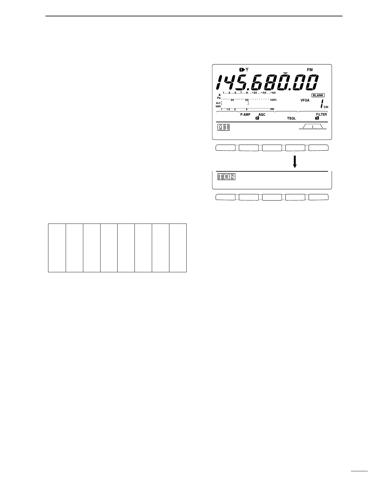
42
4
RECEIVE AND TRANSMIT
DTone squelch operation
Tone squelch operation is a method of communica-
tions using selective calling. Only received signal hav-
ing a matching tone will open the squelch. Before
communicating using tone squelch, all members of
your party must agree on the tone squelch frequency
to use.
qPush [AM/FM] to select FM mode.
wPush [MENU] several times to select M1.
ePush [F4 TON] several times to turn the tone
squelch function ON.
•“TSQL” appears
rPush [F4 TONE] for 1 sec. to enter tone frequency
set mode.
tPush [F1 TON] several times until TSQL Tone
appears, if necessary.
yRotate the tuning dial to select the desired tone
squelch frequency.
•Push [F3] for 1 sec. to select the default frequency.
uPush [MENU] to return to M1.
iCommunicate in the usual manner.
•Available tone squelch frequencies (Unit: Hz)
F 1 F 2 F 3 F 4 F 5
F 1 F 2 F 3 F 4 F 5
AGC
DUP
CMP
TON
SCP
TON
SCN
88.5Hz
TSQL
Tone
Push [F4] for 1 sec.
67.0
69.3
71.9
74.4
77.0
79.7
82.5
085.4
088.5
091.5
094.8
097.4
100.0
103.5
107.2
110.9
114.8
118.8
123.0
127.3
131.8
136.5
141.3
146.2
151.4
156.7
159.8
162.2
165.5
167.9
171.3
173.8
177.3
179.9
183.5
186.2
189.9
192.8
196.6
199.5
203.5
206.5
210.7
218.1
225.7
229.1
233.6
241.8
250.3
254.1
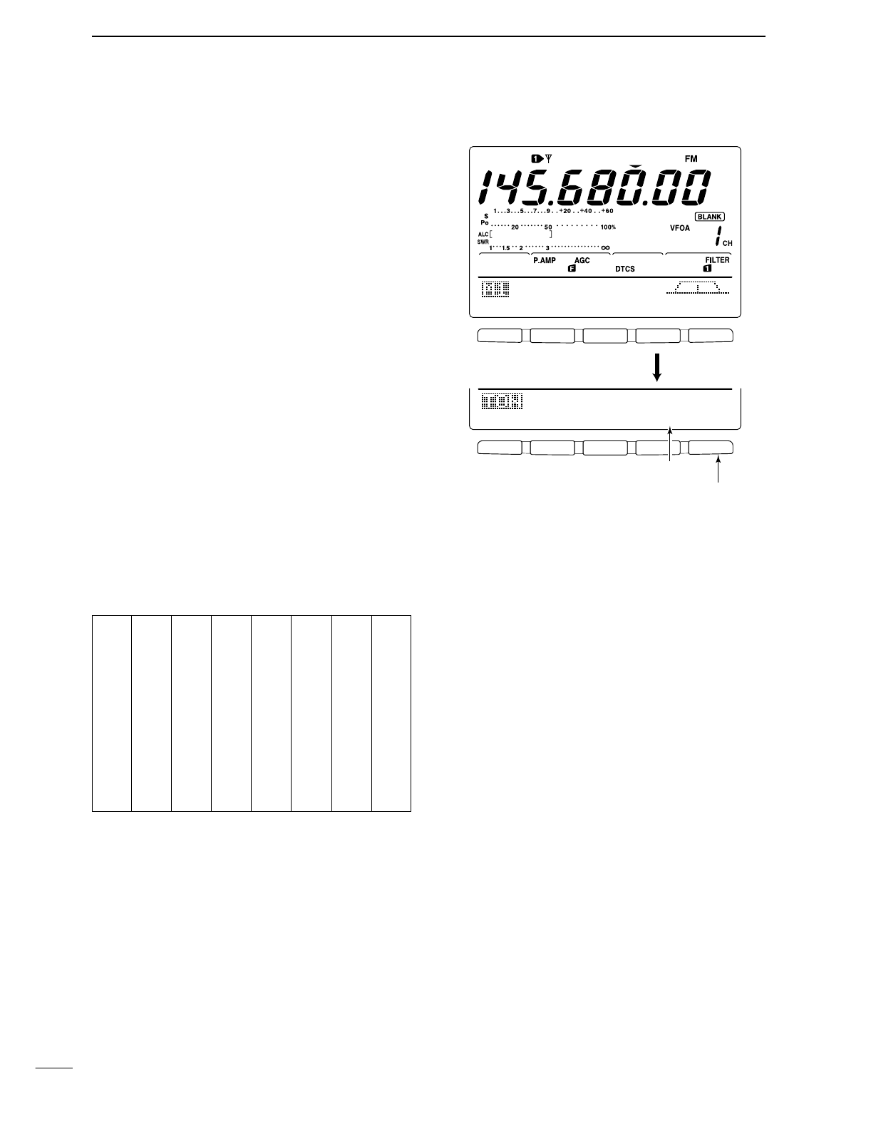
43
4RECEIVE AND TRANSMIT
DDTCS operation
DTCS function is an another method of communica-
tions using selective calling. Only received signal hav-
ing a matching 3-digit code will open the squelch.
qPush [AM/FM] to select FM mode.
wPush [MENU] several times to select M1.
ePush [F4 TON] several times to turn the DTCS
function ON.
•“DTCS” appears
rPush [F4 TON] for 1 sec. to enter tone frequency
set mode.
tPush [F1 TON] several times until DTCS Code
appears, if necessary.
yRotate the tuning dial to select the desired DTCS
code number and push [F5] to select the desired
code polarity.
NN : Normal polarity is used for both transmit and
receive.
NR : Normal polarity is used for transmit, reversed
polarity is used for receive.
RN : Reversed polarity is used for transmit, normal
polarity is used for receive.
RR : Reversed polarity is used for both transmit
and receive.
•Push [F3] for 1 sec. to select the default code and polar-
ity.
uPush [MENU] to return to M1.
iCommunicate in the usual manner.
•Available tone codes
F 1 F 2 F 3 F 4 F 5
F 1 F 2 F 3 F 4 F 5
AGC
DUP
CMP
TON
SCP
TON
SCN
O23-NN
DTCS
Code
Push [F4] for 1 sec.
Push [F5] to select the polarity
Select a code with the tuning dial.
023
025
026
031
032
036
043
047
051
053
054
065
071
072
073
074
114
115
116
122
125
131
132
134
143
145
152
155
156
162
165
172
174
205
212
223
225
226
243
244
245
246
251
252
255
261
263
265
266
271
274
306
311
315
325
331
332
343
346
351
356
364
365
371
411
412
413
423
431
432
445
446
452
454
455
462
464
465
466
503
506
516
523
526
532
546
565
606
612
624
627
631
632
654
662
664
703
712
723
731
732
734
743
754
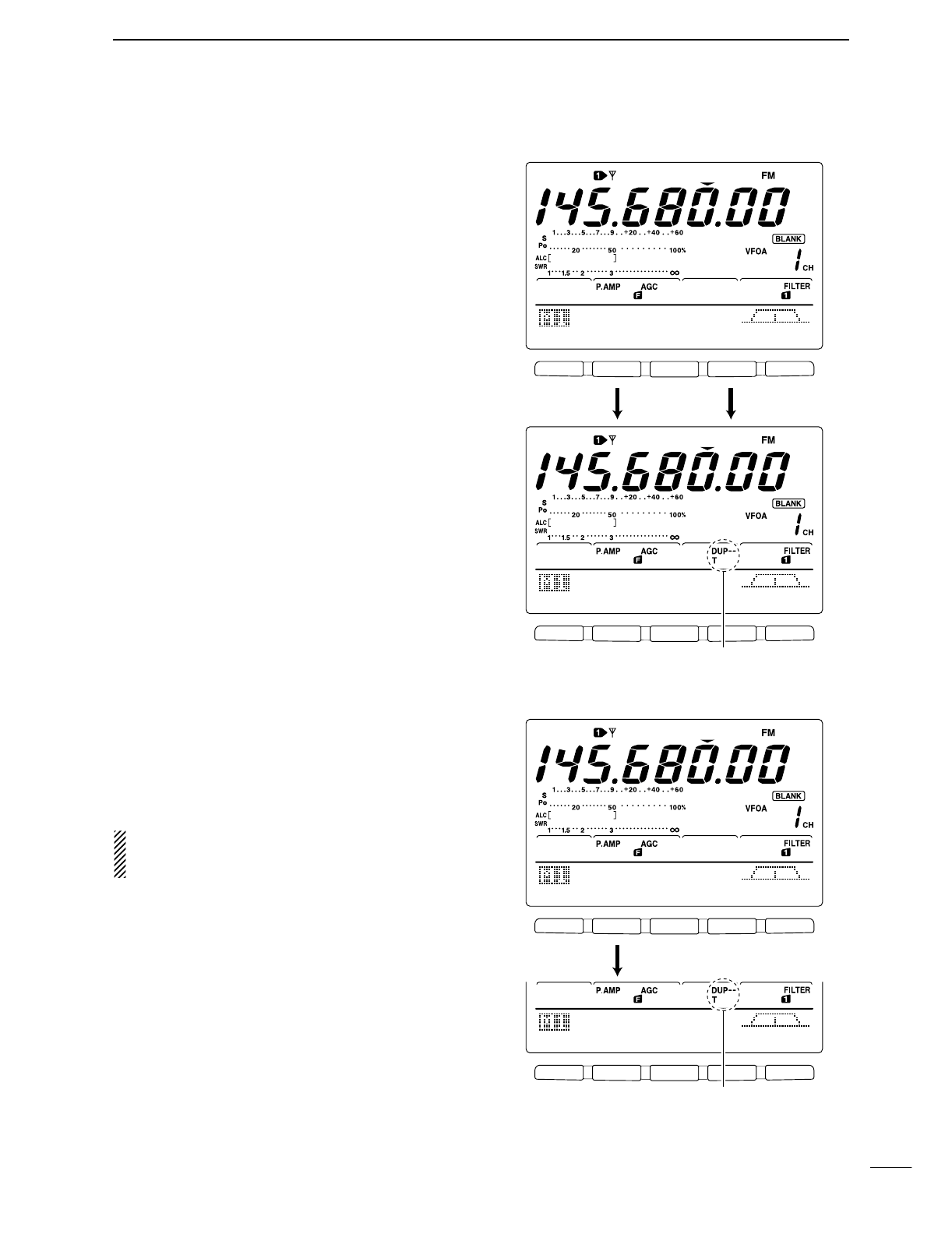
44
4
RECEIVE AND TRANSMIT
■Repeater operation
A repeater amplifies received signals and retransmits
them at a different frequency. When using a repeater,
the transmit frequency is shifted from the receive fre-
quency by an offset frequency. A repeater can be ac-
cessed using split frequency operation with the shift
frequency set to the repeater’s offset frequency.
qPush a band key to select the desired band.
wPush [A/B] to select VFO A.
ePush [AM/FM] to select FM.
•Pushing [AM/FM] toggles between AM and FM.
rRotate the tuning dial to set the repeater transmit
frequency.
tWhile M1 is selected, push [F2 DUP] several times
to set the offset direction.
•“DUP–” or “DUP+” appears
•0.100 MHz for HF, 0.500 MHz for 50 MHz and
0.600 MHz for 144 MHz band is set by default in set
mode. (p. 82)
yPush [F4 TON] to turn the repeater tone ON.
•“T” appears.
•Set the tone frequency in tone frequency set mode in
advance, if desired. (p. 45) 88.5 Hz is set by default.
To transmit a 1750 Hz European repeater tone,
push [F4 TON] while transmitting.
uCommunicate in the normal way.
DOne-touch repeater function
This function allow you to set repeater operation with
push of one switch.
➥To set the transceiver for repeater operation using
the one-touch repeater function, follow the steps q
to ras above, then push [F2 DUP] for 1 sec.
Set the offset shift direction and frequency in ad-
vance (p. 82) as well as the tone frequency (see
p. 45).
F 1 F 2 F 3 F 4 F 5
F 1 F 2 F 3 F 4 F 5
AGC
DUP
CMP
TON
SCP
AGC
DUP
CMP
TON
SCP
145.O8OOO
Push [F2], [F4]
Appear
F 1 F 2 F 3 F 4 F 5
F 1 F 2 F 3 F 4 F 5
AGC
DUP
CMP
TON
SCP
AGC
DUP
CMP
TON
SCP
145.O8OOO
Push [F2] for 1 sec.
Appear
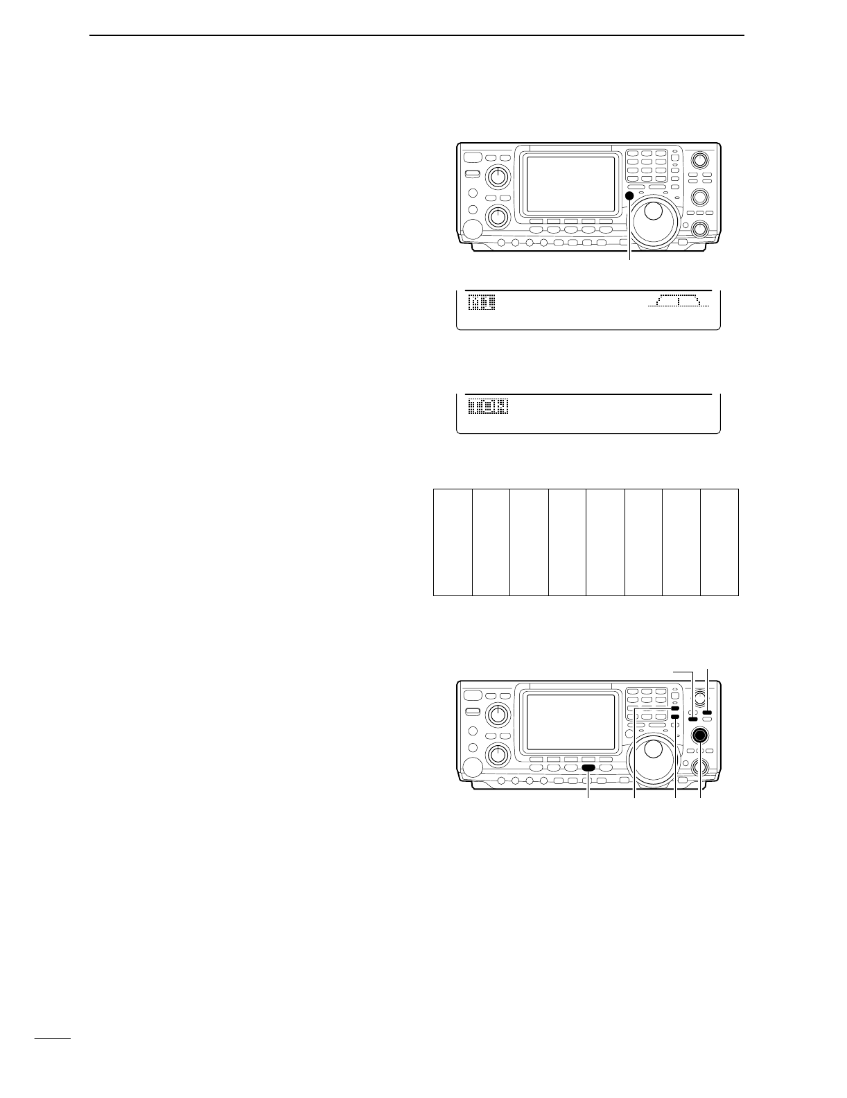
45
4RECEIVE AND TRANSMIT
DTransmit frequency monitor check
You may be able to receive the other party’s transmit
signal directly without having to go through a repeater.
This function allows you to check this.
➥While receiving, push and hold [XFC] to see if you
can receive the other party’s transmit signal directly.
•While holding [XFC], the offset direction and frequency
are displayed on the multi-function switch indicator.
DRepeater tone frequencies
The transceiver’s repeater tone frequency is set to
88.5 Hz by default. This can be changed if desired.
qWhile M1 is selected, push [F4 TON] to turn the
tone encoder ON.
•“T” appears.
wPush [F4 TON] for 1 sec. to select the tone fre-
quency set mode.
ePush [F1 TON] several times to select Rptr
Tone, if necessary.
rRotate the tuning dial to select the desired fre-
quency. (see the table at right)
tPush [MENU] to return to M1.
DStoring a non standard repeater
qTurn the auto repeater function OFF in the set
mode. (p. 83)
wPush [AM/FM] to select FM mode.
ePush [V/M], then [A/B] to select VFO A.
rRotate the tuning dial to set the repeater output fre-
quency.
•Set the tuning step if desired.
tPush [A/B] to select VFO B.
yRotate the tuning dial to set the repeater input fre-
quency.
uPush [A/B] to select VFO A.
iPush [SPLIT] to turn the split function ON.
oPush [F4 TON] to turn the previously set tone en-
coder ON.
!0 Rotate [M-CH] to select the desired memory chan-
nel.
•“BLANK” appears when blank channel is selected.
!1 Push [MW] for 1 sec. to store the contents in the se-
lected memory channel.
AGC
DUP
CMP
TON
SCP
-6OO.Ok
[XFC]
[AM/FM] [SPLIT] [A/B] [M-CH]
[MW]
[V/M]
67.0
69.3
71.9
74.4
77.0
79.7
82.5
085.4
088.5
091.5
094.8
097.4
100.0
103.5
107.2
110.9
114.8
118.8
123.0
127.3
131.8
136.5
141.3
146.2
151.4
156.7
159.8
162.2
165.5
167.9
171.3
173.8
177.3
179.9
183.5
186.2
189.9
192.8
196.6
199.5
203.5
206.5
210.7
218.1
225.7
229.1
233.6
241.8
250.3
254.1
TON
SCN
88.5Hz
Rptr
Tone
•Available tone frequencies (Unit: Hz)
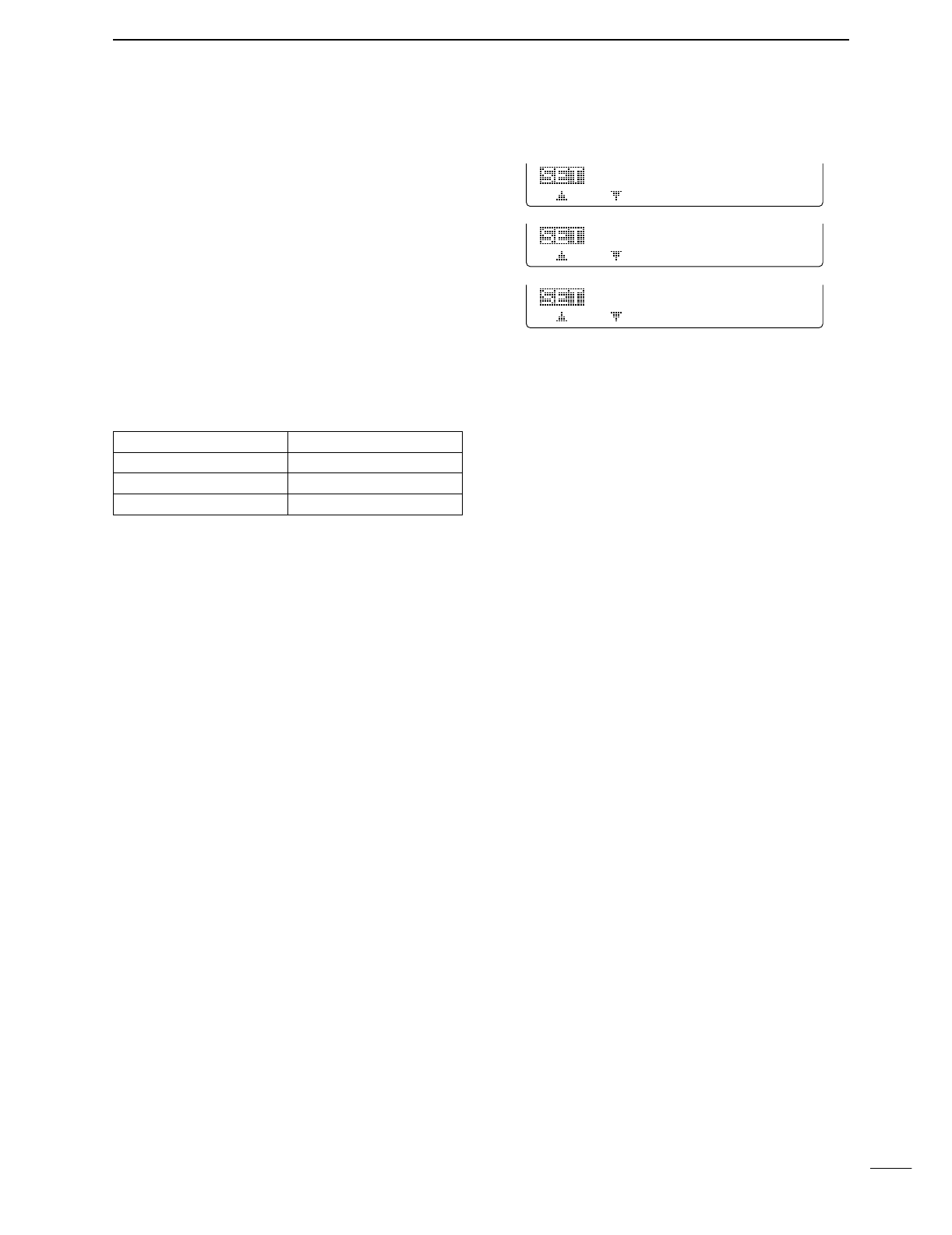
46
4
RECEIVE AND TRANSMIT
DAuto repeater function
This function automatically activates the repeater set-
tings (DUP– or DUP+ and/or tone encoder ON/OFF)
when the operating frequency falls within the general
repeater output frequency range and deactivates them
when outside of the range.
Set the auto repeater function ON-1 or ON-2 in set
mode in advance (p. 83). When set ON-1 or ON-2, re-
peater settings are automatically activated according
to the table below.
ON-1 automatically set the duplex setting and ON-2
automatically sets the duplex setting and tone encoder
automatically.
•Frequency range and offset direction
FREQUENCY RANGE DUPLEX DIRECTION
145.200–145.495 MHz minus duplex
146.610–146.995 MHz minus duplex
147.000–147.395 MHz plus duplex
18
ON-2
Auto
Repeater
18
ON-1
Auto
Repeater
18
OFF
Auto
Repeater