ICOM orporated IC-746PRO Amateur HF \ VHF Scanning Transceiver User Manual 746PRO INSTRUCTION MANUAL EN pd
ICOM Incorporated Amateur HF \ VHF Scanning Transceiver 746PRO INSTRUCTION MANUAL EN pd
Contents
- 1. Manual Part 1
- 2. Manual Part 2
Manual Part 1
![iFOREWORDWe understand making you have a choice of many dif-ferent radios in the market place.I want to take a cou-ple of moments of your time to thank you for makingyour IC-746PRO your radio of choice, and hope youagree with Icom’s philosophy of “technology first”.Manyhours of research and development went into the de-sign of your IC-746PRO.Rather than completely redesigning all areas to createa new radio, the engineering team at Icom decided tofollow in the footsteps of the IC-746 (one of the bestvalues in the marketplace) with the new “PRO”. Fo-cused on real world improvements compiled over thelast few years from letters, phone calls, E-Mails andnewsgroup postings the engineering team at Icom isproud to say “many of these changes were compiledfrom a list of suggestions from you, the amateur radiooperator!”FEATURES•32-bit Floating point DSP and 24-bit AD/DA converter•DSP IF Filter creates 102 types of filter types•All mode capability covering 160–2 m •100 Watt continuous duty cycle•All mode digital modulation and demodulation•RTTY demodulator and decoder•Twin Pass Band Tuning•RF speech compression with selectable pass band•Microphone Equalizer•SSB/CW synchronous tuningEXPLICIT DEFINITIONSREAD THIS INSTRUCTION MANUALCAREFULLY before attempting to operate thetransceiver.SAVE THIS INSTRUCTION MANUAL. Thismanual contains important safety and operating in-structions for the IC-746PRO.EXPLICIT DEFINITIONSPRECAUTIONSRWARNING RF EXPOSURE! This device emitsRadio Frequency (RF) energy. Extreme caution should beobserved when operating this device. If you have anyquestions regarding RF exposure and safety standardsplease refer to the Federal Communications CommissionOffice of Engineering and Technology’s report on Evalu-ating Compliance with FCC Guidelines for Human Radiofrequency Electromagnetic Fields (OET Bulletin 65).RWARNING HIGH VOLTAGE! NEVER attach anantenna or internal antenna connector during transmis-sion. This may result in an electrical shock or burn.RNEVER apply AC to the [DC13.8V] jack on the trans-ceiver rear panel. This could cause a fire or ruin the trans-ceiver.RNEVER apply more than 16 V DC, such as a 24 Vbattery, to the [DC13.8V] jack on the transceiver rearpanel. This could cause a fire or ruin the transceiver.RNEVER let metal, wire or other objects touch any in-ternal part or connectors on the rear panel of the trans-ceiver. This may result in an electric shock.NEVER expose the transceiver to rain, snow or any liquids.AVOID using or placing the transceiver in areas with tem-peratures below –10°C (+14°F) or above +50°C (+122°F).Be aware that temperatures on a vehicle’s dashboard canexceed 80°C (+176°F), resulting in permanent damage tothe transceiver if left there for extended periods.AVOID placing the transceiver in excessively dusty envi-ronments or in direct sunlight.AVOID placing the transceiver against walls or puttinganything on top of the transceiver. This will obstruct heatdissipation.Place unit in a secure place to avoid inadvertent use bychildren.During mobile operation, DO NOT operate the transceiverwithout running the vehicle’s engine. When transceiverpower is ON and your vehicle’s engine is OFF, the vehi-cle’s battery will soon become exhausted.Make sure the transceiver power is OFF before startingthe vehicle. This will avoid possible damage to the trans-ceiver by ignition voltage spikes.During maritime mobile operation, keep the transceiverand microphone as far away as possible from the magneticnavigation compass to prevent erroneous indications.BE CAREFUL! The heatsink will become hot when oper-ating the transceiver continuously for long periods.BE CAREFUL! If a linear amplifier is connected, set thetransceiver’s RF output power to less than the linear am-plifier’s maximum input level, otherwise, the linear ampli-fier will be damaged.Use Icom microphones only (supplied or optional). Othermanufacturer’s microphones have different pin assign-ments, and connection to the IC-746PRO may damagethe transceiver.WORD DEFINITIONRWARNING Personal injury, fire hazard or electricshock may occur.CAUTION Equipment damage may occur.NOTEIf disregarded, inconvenience only. Norisk or personal injury, fire or electricshock.](https://usermanual.wiki/ICOM-orporated/IC-746PRO.Manual-Part-1/User-Guide-183822-Page-2.png)
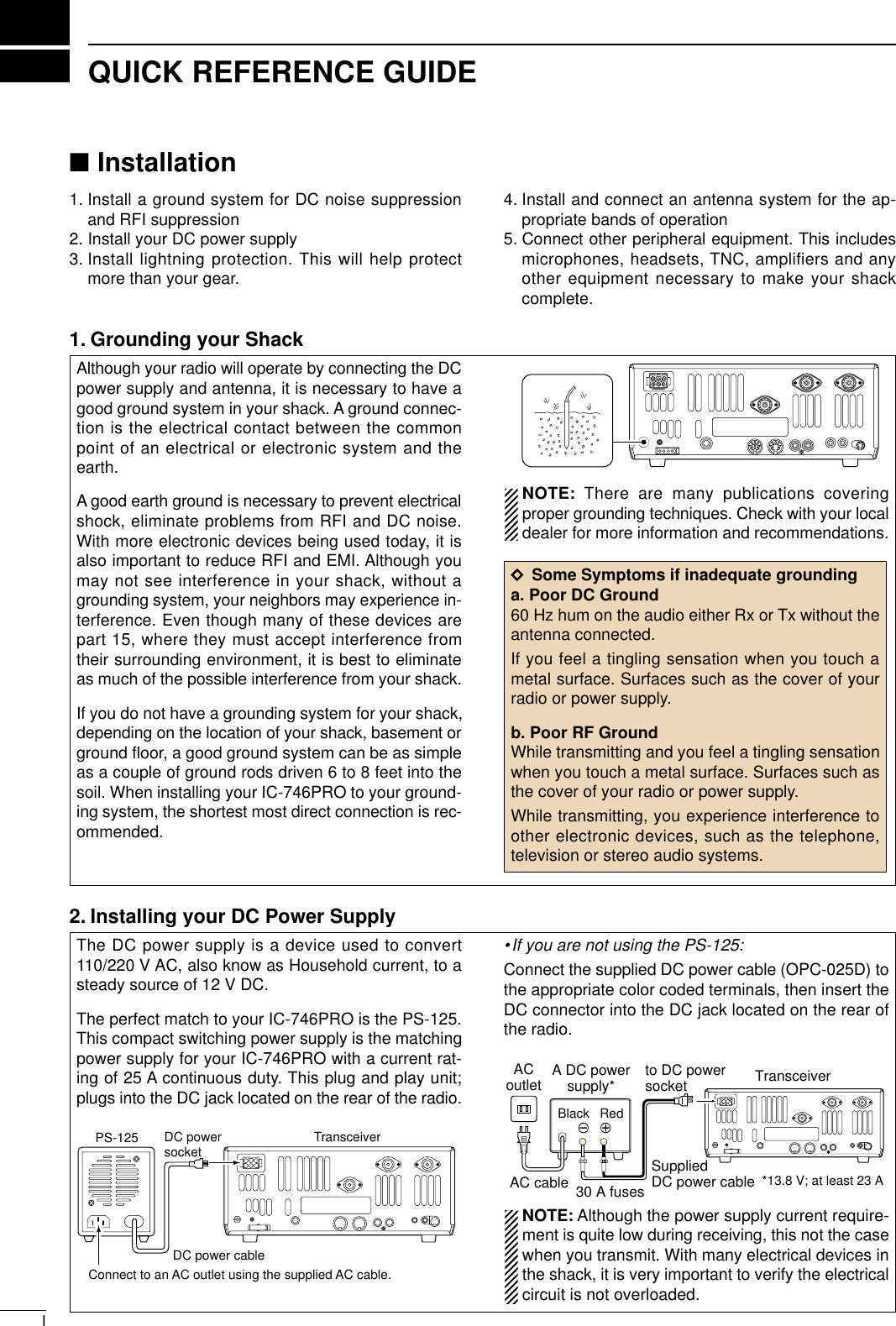
![IIQUICK REFERENCE GUIDE3. Installing lightning protectionAlthough you may not live in an area with high occur-rence for lightning storms, it is always wise to takeprecautions for lightning or static discharges. Properlightning protection not only offers protection to theham gear, but the shack and most importantly the op-erator. NOTE: There are many publications coveringproper lightning protection, check with your localdealer for more information and recommendations.Whether your IC-746PRO is your first radio or one ofmany, one of your key elements in a great shack isthe antenna system. There are three connections onthe back of your IC-746PRO, two for HF and 6 m andone for 2 m. If you are using one antenna for HF and6 m, for simplicity, connect the antenna coax to ANT1.Your IC-746PRO is equipped with an internal antennatuner (ATU) for operation on 160–6 m. This ATU is de-signed to work with an unbalanced 50 Ωfeedline. Thepurpose of the internal antenna tuner is match the im-pedance of your antenna system to as close to a50 Ωload as possible. This ATU will not operate witha long wire or ladder line (450 Ωor balanced feed-lines). An external ATU such as the AH-4 would benecessary for this kind of operation.PL-259 CONNECTOR INSTALLATION EXAMPLE30 mm ≈9⁄8in 10 mm ≈3⁄8in 1–2 mm ≈1⁄16 inRWARNING: Although a mag mount antennaworks great on a vehicle, DO NOT use with IC-746PRO on this type of antenna. CAUTION: Although your IC-746PRO has protec-tion to drop down power with a high SWR, thisdoes not completely protect the transceiver fromtransmission without an antenna. Make sure youhave an antenna connect whenever you transmitwith your radio. NOTE: There are many publications coveringproper antennas and their installation, check withyour local dealer for more information and recom-mendations.30 mm10 mm (soft solder)10 mm1–2 mmsolder solderSoftsolderCoupling ringSlide the coupling ring down. Strip the cable jacket and soft solder.Slide the connector body on and solder it.Screw the coupling ring onto the connector body.Strip the cable as shown at left. Soft sol-der the center con-ductor.qwerAntenna SWREach antenna is tuned for a specified frequencyrange and SWR may be increased out-of-range.When the SWR is higher than approx. 2.0:1, thetransceiver’s power drops to protect the final tran-sistor. In this case, an antenna tuner is useful tomatch the transceiver and antenna. Low SWR al-lows full power for transmitting even when using theantenna tuner. The IC-746PRO has an SWR meterto monitor the antenna SWR continuously.ANTENNA 1, 2[Example]: ANT1 for 1.8–18 MHz bandsANT2 for 21–50 MHz bands144 MHz ANTENNAConnect a VHF (60–144 MHz)antenna; impedance: 50 Ω.4. Installing your antenna system](https://usermanual.wiki/ICOM-orporated/IC-746PRO.Manual-Part-1/User-Guide-183822-Page-5.png)
![IIIQUICK REFERENCE GUIDE5. Connect other peripheral equipmentEveryone has his or her favorite ad-on gear; now isthe time to connect this gear! We will cover the basicdevices that can be connected to your IC-746PRO. If you do not see the particular item you are wantingto connect, refer to the Advance Connections sectionstarting on page 15.Microphones: Connect it to the eight-pin connector onthe front of the radio. MICROPHONES HM-36 SM-20■Operation1. VoiceCW Key: There are several types of keys or keyersthat can be used with your IC-746PRO.a. Lambic Key paddle: Use a 6.35(d) mm (1⁄4″)stereo plug and connect to the [ELEC-KEY] jack lo-cated on the front of the radio.b. Straight Key: Use a 6.35(d) mm (1⁄4″) mono plugand connect key to the back of the radio.c. External Keyer: Use a 6.35(d) mm (1⁄4″) monoplug and connect to the back of the radio.d. Computer Keying: Use a 6.35(d) mm (1⁄4″) monoplug and connect to the back of the radio.NOTE: You will need to select the type of keyer youare using in the Keyer Set mode. There are manyadvanced CW functions in this set mode, until youhave a full understanding of these functionschange only the items necessary.STRAIGHT KEY(+)(_)CW KEYA straight key can be used when the internal electronic keyer is turned OFF in keyer set mode. (p.34)(dot)(com)(dash)2. CW](https://usermanual.wiki/ICOM-orporated/IC-746PRO.Manual-Part-1/User-Guide-183822-Page-6.png)
![IVQUICK REFERENCE GUIDE3. Other convenient itemsHeadphones:A 6.35(d) mm (1⁄4″) mono jack for operation withoutusing the internal or external speakers. Perfect for op-eration without disturbing others in the room.External Speaker:A 3.5(d) mm (1⁄8″) mono jack for operation with an ex-ternal speaker. (Input impedance: 8 Ω/Max. inputpower: 5 W)EXTERNAL SPEAKERSP-21 (optional)HEADPHONES1. Before powering up your radio, you may want tomake sure the following controls are set in the fol-lowing positions:•[AF] : Commonly referred to as the vol-ume: fully CCW.•[NR] : The noise reduction control: fullyCCW.•[MIC GAIN] : The mic gain: fully CCW.•[RF/SQL] : The control for the RF Gain andSquelch circuits: 12 o’clock.•[CW PITCH] : The control for the CW pitch:12 o’clock.•[KEY SPEED] : Internal CW Keyer Speed: fullyCCW•[NOTCH] : Control for the manual notch:12 o’clock2. Resetting the CPU: Although you have purchaseda brand new radio, some settings may be changedfrom the factory defaults from the CQ process. Soyour radio can start from Factory Defaults resettingthe CPU is necessary.[POWER] [F-INP] [M-CL]■Your first contactNow you should have your IC-746PRO installed inyour shack, and like a kid on his birthday, you areprobably excited to get on the air. We would like totake you through a few basic operation steps to makeyour first “On The Air” an enjoyable experience. DTurning on the radio](https://usermanual.wiki/ICOM-orporated/IC-746PRO.Manual-Part-1/User-Guide-183822-Page-7.png)
![VQUICK REFERENCE GUIDEDJust listening3. Verify proper antenna has been selected.1. Select the desired band Your IC-746PRO easy way of changing bands usingthe keypad located just above the tuning knob on theright hand side of the display. You will notice eachswitch has two sets of numbers; one set of numbersrepresents the band selection.•Say you want to go to 20 meters or 14 MHz; youwould push the [145]. This will immediately changethe displayed operating frequency to the 20-meterband. This system is the triple band stacking regis-ters. For more details on this system refer to p. 19.GENE5002172482891451041863.521.8173144ENTDirectly below the keypad is the tuning knob. This willallow you to dial in the frequency you want to oper-ate. You will notice the tuning speed [TS] is 10 Hz res-olutions. Page 22 will instruct you on how to set thetuning speed [TS] for 1 Hz resolution.NOTE: Although you can directly enter the fre-quency with the keypad, using the Band StackingRegisters and the tuning knob is the most popularmethod of hoping around the bands. For more in-formation regarding the direct frequency entrymethod, refer to p. 22.You IC-746PRO has three antenna connectors. Twofor HF and 6m and a one for 2m. The selection for 2mis automatic, where the HF and 6m is user selectablefor either one of the antenna jacks. For the first timeuse, the antenna selector should show “” on thedisplay of your radio. Verify the antenna selected onthe display is the antenna port your connected yourantenna.Either “1” or “2” appears.*No indicator appear during 144 MHz operation.Adjust this control to a comfortable audio level.AF RF/SQLNo audio output Max. audio outputDecreases Increases2. Tune to the desired frequency4. Adjust audio output](https://usermanual.wiki/ICOM-orporated/IC-746PRO.Manual-Part-1/User-Guide-183822-Page-8.png)
![VIQUICK REFERENCE GUIDEDWhat are you hearing? Stop and focus on what you are hearing. Do you heara lot of noise? Is the signal intelligible? Are you set upfor the right mode? How about the filters?1. Verify modeYour IC-746PRO has many features to reduce QRMand QRN from the desired signal. a. Noise Reduction: The noise reduction system onyour IC-746PRO is part of the 32-bit DSP. This isused to reduce the hiss and QRM levels. To acti-vate, push the [NR] switch located just to the rightof the [PHONES] jack.b. Adjusting the Noise Reduction: The noise re-duction is completely variable on how much of theDSP Noise Reduction is used. Located just abovethe [NR] switch, this is where the [NR] level con-trol. Hint! How much [NR] will depend on the S/N ratio, Signalto Noise. Just using the [NR] may cause the signalto become distorted. To keep this from happening,using the [NR] along with the [RF GAIN] and Filterbandwidths will allow you to zero in on the desiredsignal with as little QRM as possible.Noise reduction ONNoise reduction OFFNR NOTCHOFFDecreases IncreasesAGC DUP CMP TBW SCP[NR] [NR]AppearsAlthough your IC-746PRO will automatically selectUSB or LSB in the HF bands, it will not select any ofthe other modes. You will need to select the propermode whether CW, RTTY, AM or FM.Hint! The Triple Band Stacking Registers will memorizethe last three frequencies used in the band, as wellas the Mode, Filter, Tuner and AGC settings. Mak-ing band hoping much easier.SSBCW/RTTYAM/FM2. Reducing interference](https://usermanual.wiki/ICOM-orporated/IC-746PRO.Manual-Part-1/User-Guide-183822-Page-9.png)
![VIIQUICK REFERENCE GUIDEc. Notch: There are two notch systems on your IC-746PRO. •Automatic:The automatic notch will track up to threeheterodynes. This is great for eliminating hetero-dynes on 80 and 160 meters, and those annoyingtune up signals across the band. Once selected anicon will appear “ANOTCH” on the display.•Manual:The Manual notch provides 70 dB of atten-uation to pin point an interfering signal. The 12 o’-clock position is on the operating frequency, turningthe Notch knob clockwise moves the notch up theband and counter clockwise will move the notchdown the band. Once selected an icon will appear“NOTCH” on the display. NOTE: Your IC-746PRO is equipped with multipleAGC circuits. This allows the DSP to filter out inter-fering signals and QRM, while also taking this in-terference out of the AGC. Bottom line, this will ei-ther eliminate or greatly reduce the pumping of theAGC from the interfering signal.AGC DUP CMP TBW SCP[A/NOTCH] [NOTCH]Notch function indicatorsNR NOTCHLow freuency High frequencyHint! The Automatic Notch will not operated in the SSBdata, CW or RTTY modes.d. Filters: Your IC-746PRO has an incredible IF DSPbased filter network with over 100 settings. •Dial in your filters: By pushing [FILTER] for 1 sec.,you enter the filter set mode. This is where you areable set the three filter presets. Across the bottom ofthe display you will see the “BW” icon. The switch di-rectly below, along with the tuning dial, will be usedto select the changes you will make.BW• Filter set mode indicationShows the selected filter and passband width.BW• Indication while settingWhile pushing [F1 BW], rotate the tuning dial to setpassband width.Reverses AppearsAGC DUP CMP TBW SCP[FILTER]The selected filter width is indicatedfor approx. 1 sec. when [FILTER] ispushed. Filter selection](https://usermanual.wiki/ICOM-orporated/IC-746PRO.Manual-Part-1/User-Guide-183822-Page-10.png)
![VIIIQUICK REFERENCE GUIDEd. Filters:— continued•On the fly adjustment: Once the adjustments havebeen made in the filter set mode, you can make onthe fly changes by using the Twin Pass Band Tuning,Twin PBT. You will be able to see the effects of theTwin PBT on the upper left hand side of the screen.NOTE: The Twin PBT filters shift the two IF DSPfilters (See Diagrams below and right). This featureallows both an IF shift as well as a narrowing of thePass Band. Although you can narrow the passband by shifting the two filters, this does not nar-row both filters, thus the filter shape is not nar-rowed. You may hear some signal artifacts passthrough this filter adjustment. PBT operation exampleBW• Filter set mode indicationShows the selected filter and passband width.BW• Indication while PBT settingAppears when passband is shifted.*Pushing [PBTC] for 1 sec., the shifted value return to default setting and the “dot” disappears.AGC DUP CMP TBW SCPPassband width and shifting value areindicated while [TWIN PBT] is operated.[TWIN PBT] control[PBTC]Appears when PBT is used.One of “1,” “2” or “3” isdisplayed for selected filternumber indications.interferenceinteferenceinterference desired signaldesired signalpass bandIF center frequencyCenter Passband PassbandIF center freq.IF shift](https://usermanual.wiki/ICOM-orporated/IC-746PRO.Manual-Part-1/User-Guide-183822-Page-11.png)
![IXQUICK REFERENCE GUIDEOnce you have mastered your filter settings, one lastfeature to enable the most intelligible audio is the ac-tual audio tone you hear. You can adjust the equal-ization of your received audio ±5dB.qPush [MENU] several time, or until M2 is shown onthe display.wPush [F4 TCN] for the Tone Control set mode.ePush the appropriate mode switch to adjust SSB,AM or FM.rPush [F1 ≤] or [F2 ≥] to change to the desiredcomponent.[F1 ≤]Tuning dial[MENU][F2 ≥] [F4 TCN]3. RX Tone Control:1. RX BassThis item adjusts the bass level of the receive audiotone from –5 dB to +5 dB in 1 dB steps.RX Bass SSBO32. RX TrebleThis item adjusts the treble level of the receive audiotone from –5 dB to +5 dB in 1 dB steps.RX Treble SSBO4We hope these pointers have been helpful. Now youare ready for the “Ready to call CQ?”.■Ready to call CQ?The 32-bit DSP in your IC-746PRO is capable of givingyou the type of transmit audio for your SSB Operation.POWERTRANSMITPHONESELEC-KEYMICNRA/NOTCHTUNERANTHF/VHF TRANSCEIVERNRNOTCHAFMIC GAINRF PWRCW PITCHF 1F 2F 3F 4F 5XFCMP-WGENE5002172482891451041863.521.8173144ENTMP-RTX RX LOCKTWIN PBTM-CHRITCLEAR∂TXRIT/∂TXTSSPLITPBTCF-INPA/BV/MMWM-CLKEY SPEEDP.AMP/ATTNBVOX/BK-INMONITORCALLLOCK/SPCHRF/SQLi746PROMENU SSBCW/RTTYAM/FMFILTER[NR]: Max. CCW [NOTCH]: Max. CCW[AF]: Max. CCW[TRANSMIT]: OFF[MIC GAIN]: Max. CCW[RF PWR]: Max. CCW [CW PITCH]: 12 o’clock[RF/SQL]: 12 o’clock[KEY SPEED]: Max. CCW1. Setting up your transmit audio2. Mic GainThe microphone gain is used for proper transmitaudio level for full output power. Although the handmicrophone supplied with your IC-746PRO should re-quire a setting of the [MIC GAIN] you should find a10–11 o’clock position.](https://usermanual.wiki/ICOM-orporated/IC-746PRO.Manual-Part-1/User-Guide-183822-Page-12.png)
![XQUICK REFERENCE GUIDEVerify you have selected a clear frequencyand call out your CQ!The capable of changing the pass band of your trans-mit audio, is at your finger tip. Regardless of the con-dition of the speech compressor, you can adjust byselecting the [F4 TBW]. You will find this located on the M1 menu. Pushing the[F4 TBW] for 1 sec. you can step through the TXaudio band pass.There are three levels of audio passband available(Wide, Mid, and Nar). TX Audio Passband widthsWide :2.9 kHz ; Great Full AudioMid :2.6 kHz ; Great for operators withdeep full voicesNar :2.0 kHz ; Great for breaking throughpile upsF 1F 2F 3F 4F 5F 1 F 2 F 3 F 4 F 5AGC DUP CMP TBW SCPAGC DUP CMP TBW SCPTX BW=WIDEPush [F4]Push [F4] for 1 sec. to select the transmit filter width.The selected transmit filter width is displayed for approx. 1 sec.3. DSP TX Audio Pass Band4. Microphone EqualizerAlthough these bandwidths are fixed, the MicrophoneTone Control will give you more audio control for yourVoice operation on SSB, AM, and FM modes. YourIC-746PRO is equipped with a very powerful equal-izer system with 121 possible combinations. This isachieved by using the separate bass and treble ad-justments. The default for both the Base and Trebleis at 0 dB. Entering Microphone Tone Control set mode:qPush [MENU] several time, or until M2 is shown onthe display.wPush [F4 TCN] for the Tone Control set mode.ePush the appropriate mode switch to adjust SSB,AM, or FM.rPush [F1 ≤] or [F2 ≥] to change to the desiredcomponent.Hint! Voice patterns and audio characteristics vary witheach operator, therefore the [MIC GAIN], DSP TXAudio Pass Band and Microphone Tone Controlsettings will be different for each operator. Actual onair experimenting is necessary to get the just rightsound.[F1 ≤]Tuning dial[MENU][F2 ≥] [F4 TCN]1. TX BassThis item adjusts the bass level of the transmit audiotone from –5 dB to +5 dB in 1 dB steps.TX Bass SSBO12. TX TrebleThis item adjusts the treble level of the transmit audiotone from –5 dB to +5 dB in 1 dB steps.TX Treble SSBO2](https://usermanual.wiki/ICOM-orporated/IC-746PRO.Manual-Part-1/User-Guide-183822-Page-13.png)
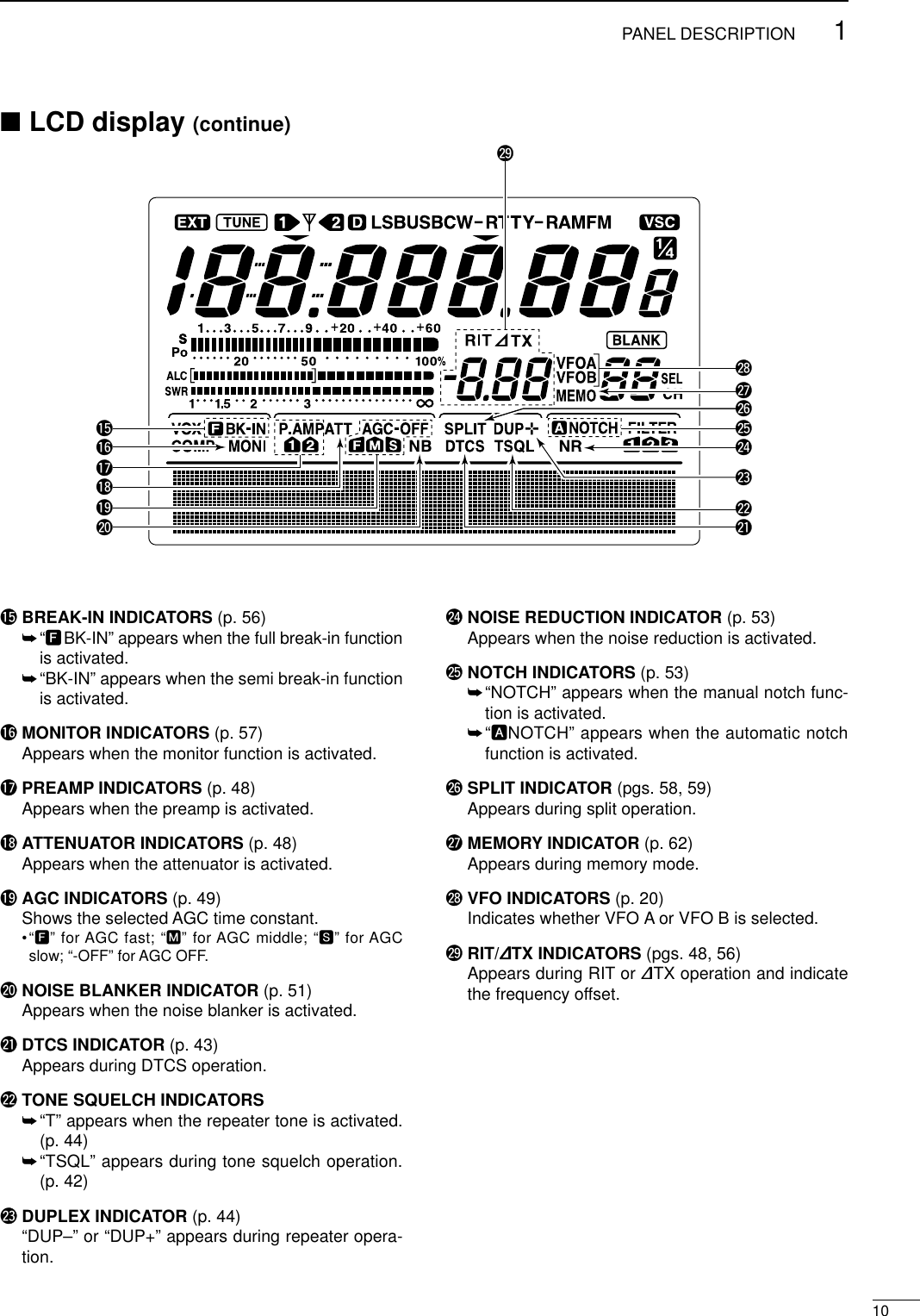
![11PANEL DESCRIPTION■Front panelqPOWER SWITCH [POWER]➥Push momentarily to turn power ON.•Turn the optional DC power supply ON in advance.➥Push for 1 sec. to turn power OFF.wTRANSMIT SWITCH [TRANSMIT]Selects transmitting or receiving.•The [TX] indicator lights red while transmitting and the[RX] indicator lights green when the squelch is open.eHEADPHONE JACK [PHONES]Accepts headphones.•Output power: 5 mW with an 8 Ωload.•When headphones are connected, the internal speakeror connected external speaker does not function.rELECTRONIC KEYER JACK [ELEC-KEY] (p. 14)Accepts a paddle to activate the internal electronickeyer for CW operation.•Selection between the internal electronic keyer, bug-keyand straight key operation can be made in keyer setmode. (p. 34)•A straight key jack is separately available on the rearpanel. See [KEY] on p. 7.•Keyer polarity (dot and dash) can be reversed in keyerset mode. (p. 34)•4-channel memory keyer is available for your conve-nience. (p. 30)tMICROPHONE CONNECTOR [MIC]Accepts the supplied or optional microphone.•See p. 100 for appropriate microphones.•See p. 12 for microphone connector information.yRF GAIN CONTROL/SQUELCH CONTROL[RF/SQL] (outer control)Adjusts the RF gain and squelch threshold level.The squelch removes noise output from the speaker(closed condition) when no signal is received.•The squelch is particularly effective for FM. It is alsoavailable for other modes.•12 to 1 o’clock position is recommended for any settingof the [RF/SQL] control.•The control can be set as ‘Auto’(RF gain control in SSB,CW and RTTY; squelch control in AM and FM) orsquelch control (RF gain is fixed at maximum) in setmode as follows. (p. 81)•When setting as RF gain/squelch controlRecommended levelRF gain adjustablerangeMaximum RF gainS-meter squelchNoise squelch (FM mode)Squelch is open.MODESSB, CWRTTYAM, FMAUTORF GAINSQLSQLSET MODE SETTINGSQLSQLRF GAIN + SQLRF GAIN + SQLRF GAIN + SQL(dot)(com)(dash)POWERTRANSMITPHONESELEC-KEYMICNRA/NOTCHTUNERANTHF/VHF TRANSCEIVERNRNOTCHAFMIC GAINRF PWRCW PITCHF 1F 2F 3F 4F 5XFCMP-WGENE5002172482891451041863.521.8173144ENTMP-RTX RX LOCKTSSPLITF-INPA/BKEY SPEEDP.AMP/ATTNBVOX/BK-INMONITORCALLLOCK/SPCHRF/SQLi746PROMENU SSBCW/RTTYAM/FMFILTERqwertyuio !0 !1!4!5!6!7 !3 !2](https://usermanual.wiki/ICOM-orporated/IC-746PRO.Manual-Part-1/User-Guide-183822-Page-14.png)
![21PANEL DESCRIPTION•When functioning as RF gain control(Squelch is fixed open; SSB, CW, RTTY only)•When functioning as squelch control(RF gain is fixed at maximum.)While rotating the RF gain control, noise may beheard. This comes from the DSP unit and does notindicate an equipment malfunction.uMIC GAIN CONTROL [MIC GAIN]Adjusts microphone input gain.•The transmit audio tone in SSB, AM and FM modes canbe adjusted in tone control set mode. (p. 88)✔How to set the microphone gain.Set the [MIC] control so that the ALC meter sometimesswings during normal voice transmission in SSB mode.iAF CONTROL [AF] (inner control)Varies the audio output level from the speaker.oRF POWER CONTROL [RF PWR] Continuously varies the RF output power from min-imum (less than 5 W*) to maximum (100 W*).*AM mode: less than 5 W to 40 W!0 CW PITCH CONTROL [CW PITCH] (p. 28)Shifts the received CW audio pitch and monitoredCW audio pitch without changing the operating fre-quency.•The pitch can be changed from 300 to 900 Hz in approx.25 Hz steps.!1 ELECTRONIC CW KEYER SPEED CONTROL[KEY SPEED] (p. 28)Adjusts the internal electronic CW keyer’s speed.•6 wpm (min.) to 60 wpm (max.) can be set.!2 AUTO NOTCH/MANUAL NOTCH SWITCH[A/NOTCH] (p. 53)Toggles the notch function between manual and au-tomatic when pushed.•“NOTCH” appears when manual; “ANOTCH” appearswhen automatic notch is selected.!3 NOTCH CONTROL [NOTCH] (outer control; p. 53)Adjusts the notch filter frequency to remove a inter-ference signal.!4 ANTENNA SELECTOR SWITCH [ANT] (p. 75)Switches the antenna connector selection betweenANT1 and ANT2 when pushed. !5 NOISE REDUCTION LEVEL CONTROL [NR] (inner control; p. 53)Adjusts the noise reduction level when the noise re-duction is in use. Set for maximum readability.!6 ANTENNA TUNER SWITCH [TUNER] (pgs. 76,77)➥Turns the antenna tuner ON and OFF (bypass)when pushed momentarily.➥Starts to tune the antenna manually whenpushed for 1 sec.•When the tuner cannot tune the antenna, the tuningcircuit is bypassed automatically after 20 sec.!7 NOISE REDUCTION SWITCH [NR] (p. 53)Switches the noise reduction ON and OFF.•“NR” appears while the noise reduction is activated.NR NOTCHOFFDecreases IncreasesNR NOTCHLow freuency High frequencySlow FastKEY SPEEDCW PITCHIncreasesDecreasesRF PWRIncreasesDecreasesAF RF/SQLNo audio output Max. audio outputDecreases IncreasesMIC GAINRecommended level for an Icom microphoneIncreasesDecreasesSquelch is open.S-meter squelchS-meter squelchthresholdNoise squelch threshold (FM mode)Shallow DeepNoise squelch (FM mode)Minimum RF gainAdjustablerangeMaximum RF gain](https://usermanual.wiki/ICOM-orporated/IC-746PRO.Manual-Part-1/User-Guide-183822-Page-15.png)
![31PANEL DESCRIPTION■Front panel (continued)!8 MULTI-FUNCTION SWITCHES [F1]–[F5]➥Push to select the function indicated in the LCDdisplay above these switches. (p. 11)•Functions vary depending on the operating condition.➥Push to input a character for memory keyer pro-gramming or memory name. (pgs. 31, 66)!9 MENU SWITCH [MENU]Push to change the set of functions assigned to themulti-function switches.•Toggles between menu 1 (M1) and menu 2 (M2).@0 MODE SWITCHESSelects the desired mode. (p. 23)•Announces the selected mode when an optional UT-102is installed. (p. 89)➥Selects USB and LSB mode alternately.➥Selects SSB data mode (USB-D, LSB-D)when pushed for 1 sec. in SSB mode.➥Selects CW and RTTY mode alternately.➥Switches CW and CW-R (CW reverse)mode when pushed for 1 sec. in CWmode.➥Switches RTTY and RTTY-R (RTTY re-verse) mode when pushed for 1 sec. inRTTY mode.➥Selects AM and FM mode alternately.➥Selects AM/FM data mode (AM-D, FM-D)when pushed for 1 sec. AM/FM mode.@1 PREAMP/ATTENUATOR SWITCH [P.AMP/ATT](p. 48)➥Push momentarily to toggle between preamp-1and preamp-2.•“P.AMP1” activates for HF all bands.•“P.AMP2” activates high-gain preamp for 24 MHzband and above.➥Push for 1 sec. to toggle the attenuator functionON and OFF.✔What is the preamp?The preamp amplifies received signals in the front end cir-cuit to improve the S/N ratio and sensitivity. Select “P.AMP1”or “P.AMP2” when receiving weak signals.✔What is the attenuator?The attenuator prevents a desired signal from distortingwhen very strong signals are near the desired frequency, orwhen very strong electric fields, such as from a broadcast-ing station, are near your location.@2 NOISE BLANKER SWITCH [NB] (p. 51)➥Switches the noise blanker ON and OFF whenpushed. The noise blanker reduces pulse-typenoise such as that generated by automobile igni-tion systems. This function cannot be used forFM, or non-pulse-type noise.•“NB” appears while the noise blanker is activated.➥Enters the noise blanker level set mode whenpushed for 1 sec.AM/FMCW/RTTYSSBTYNRA/NOTCHTUNERANTHF/VHF TRANSCEIVERNRNOTCHAFMIC GAINRF PWRCW PITCHF 1F 2F 3F 4F 5XFCMP-WGENE5002172482891451041863.521.8173144ENTMP-RTX RX LOCKTWIN PBTM-CHRITCLEAR∂TXRIT/∂TXTSSPLITPBTCF-INPA/BV/MMWM-CLKEY SPEEDP.AMP/ATTNBVOX/BK-INMONITORCALLLOCK/SPCHRF/SQLi746PROMENU SSBCW/RTTYAM/FMFILTER#7#6#5#4#3#2#1#0!9 @0 @1!8 @2 @3 @4 @6@5 @7 @8 @9](https://usermanual.wiki/ICOM-orporated/IC-746PRO.Manual-Part-1/User-Guide-183822-Page-16.png)
![41PANEL DESCRIPTION@3 VOX/BREAK-IN SWITCH [VOX/BK-IN]➥In SSB, AM and FM modes, push momentarily toturn the VOX function ON and OFF (p. 54); pushfor 1 sec. to enter VOX set mode (p. 54).➥In CW mode, push momentarily to turn the semibreak-in, full break-in or break-in OFF (p. 56);push for 1 sec. to enter break-in set mode (p. 56).✔What is the VOX function?The VOX function (voice operated transmission) starts trans-mission without pushing the transmit switch or PTT switchwhen you speak into the microphone; then, automatically re-turns to receive when you stop speaking.✔What is the break-in function?The break-in function switches transmit and receive with CWkeying. Full break-in (QSK) can monitor the receive signalduring keying.@4 MONITOR SWITCH [MONITOR] (p. 57)➥Monitors your transmitted signal.➥Enters to monitor set mode when pushed for1 sec.@5 FILTER SWITCH [FILTER] (p. 50)➥Selects one of 3 IF filter settings.➥Enters the filter set mode when pushed for 1 sec.@6 CALL SWITCH [CALL] (p. 64)Selects the call channel when pushed momentarily.@7 TUNING DIAL (p. 21)Changes the displayed frequency, selects set modeitems, etc.@8LOCK/SPEECH SWITCH [LOCK/SPCH]➥Push momentarily to toggle the dial lock functionON and OFF. (p. 53)➥Pushing for 1 sec. announces the selected read-out frequency and S-meter indication when anoptional UT-102 is installed. (p. 89)@9 RIT/∂TX CONTROL [RIT/∂TX] (pgs. 48, 56)Shifts the receive and/or transmit frequency withoutchanging the transmit and/or receive frequencywhile the RIT and/or ∂TX functions are ON.•Rotate the control clockwise to increase the frequency,or rotate the control counterclockwise to decrease thefrequency.•The shift frequency range is ±9.99 kHz in 10 Hz steps(or ±9.999 kHz in 1 Hz steps).#0 RIT SWITCH [RIT] (p. 48)➥Turns the RIT function ON and OFF when pushed.•Use the [RIT/∂TX] control to vary the RIT frequency.➥Adds the RIT shift frequency to the operating fre-quency when pushed for 1 sec.✔What is the RIT function?The RIT (Receiver Incremental Tuning) shifts the receive fre-quency without shifting the transmit frequency.This is useful for fine tuning stations calling you on an off-fre-quency or when you prefer to listen to slightly different-sounding voice characteristics, etc.#1 CLEAR SWITCH [CLEAR] (pgs. 48, 56)Clears the RIT/∂TX shift frequency when pushedfor 1 sec.#2 ∂TX SWITCH [∂TX] (p. 57)➥Turns the ∂TX function ON and OFF whenpushed.•Use the [RIT/∂TX] control to vary the ∂TX frequency.➥Adds the ∂TX shift frequency to the operatingfrequency when pushed for 1 sec.✔What is the ∂TX function?The ∂TX shifts the transmit frequency without shifting the re-ceive frequency. This is useful for simple split frequency op-eration in CW, etc.#3 MEMORY CHANNEL SELECTOR [M-CH] (p. 62)Select a memory channel.•Rotate clockwise to increase the memory channel; ro-tate counterclockwise to decrease the memory channel.#4 VFO/MEMORY SWITCH [VFO/MEMO]➥Switches the selected readout operating modebetween the VFO mode and memory mode whenpushed. (pgs. 20, 61)➥Transfers the memory contents to VFO whenpushed for 1 sec. (p. 65)#5 MEMORY CLEAR SWITCH [M-CL] (p. 62)Clears the selected readout memory channel con-tents when pushed for 1 sec. in memory mode.•The channel becomes a blank channel.•This switch does not function in VFO mode.#6 MEMORY WRITE SWITCH [MW] (p. 63)Stores the selected readout frequency and operat-ing mode into the displayed memory channel whenpushed for 1 sec.•This function is available both in VFO and memorymodes.#7 PBT CLEAR SWITCH [PBTC] (p. 52)Clears the PBT settings when pushed for 1 sec.Low shift High shiftRIT/∂TX](https://usermanual.wiki/ICOM-orporated/IC-746PRO.Manual-Part-1/User-Guide-183822-Page-17.png)
Monitors the transmit frequency when pushed andheld.•While pushing this switch, the transmit frequency can bechanged with the tuning dial, keypad or memo pad.•When the split lock function is turned ON, pushing [XFC]cancels the dial lock function. (p. 60)#9 MEMO PAD-WRITE SWITCH [MP-W] (p. 67)Programs the selected readout frequency and op-erating mode into a memo pad.•The 5 most recent entries remain in memo pads.•The transmit frequency is programmed when pushed to-gether with [XFC].•The memo pad capacity can be expanded from 5 to 10in set mode for your convenience. (p. 84)$0 TRANSMIT INDICATOR [TX]Lights red while transmitting.$1 MEMO PAD-READ SWITCH [MP-R] (p. 67)Each push calls up a frequency and operatingmode in a memo pad. The 5 (or 10) most recentlyprogrammed frequencies and operating modes canbe recalled, starting from the most recent.•The memo pad capacity can be expanded from 5 to 10in set mode for your convenience. (p. 84)$2 RECEIVE INDICATOR [RX]Lights green while receiving a signal and when thesquelch is open.$3 LOCK INDICATOR [LOCK] (p. 53)Lights when the dial lock function is activated.$4 QUICK TUNING SWITCH [TS] (p. 21)➥Turns the quick tuning step ON and OFF.•While the quick tuning indicator is displayed, the fre-quency can be changed in programmed kHz steps.•0.1, 1, 5, 9, 10, 12.5, 20 and 25 kHz quick tuningsteps are available.➥While the quick tuning step is OFF, turns the 1 Hzstep ON and OFF when pushed for 1 sec.•1 Hz indication appears in and the frequency can bechanged in 1 Hz steps.➥While the quick tuning step is ON, enters thequick tuning step set mode when pushed for1 sec.$5 VFO SELECT SWITCH [A/B] (p. 20)➥Push to toggle between VFO A and VFO B.➥Push for 1 sec. to equalize the frequency and op-erating mode of the two VFO’s. Quick tuning indicator51PANEL DESCRIPTIONNRA/NOTCHNERANTHF/VHF TRANSCEIVERNRNOTCHAFMIC GAINRF PWRCW PITCHF 1F 2F 3F 4F 5XFCMP-WGENE5002172482891451041863.521.8173144ENTMP-RTX RX LOCKTWIN PBTM-CHRITCLEAR∂TXRIT/∂TXTSSPLITPBTCF-INPA/BV/MMWM-CLKEY SPEEDP.AMP/ATTNBVOX/BK-INMONITORCALLLOCK/SPCHRF/SQLi746PROMENU SSBCW/RTTYAM/FMFILTER$7$4$5$6$3$2$1$0#9#8%2 %0 $9 $8%1](https://usermanual.wiki/ICOM-orporated/IC-746PRO.Manual-Part-1/User-Guide-183822-Page-18.png)
![61PANEL DESCRIPTION$6 SPLIT SWITCH [SPLIT]➥Turns the split function ON and OFF whenpushed.(p. 59)➥Turns the quick split function ON, when pushedfor 1 sec. (p. 60)•The offset frequency is shifted from the displayed fre-quency. •The quick split function can be turned OFF using setmode. (p. 82)➥Turns the split function ON and sets the transmitfrequency after inputting an offset frequency withthe keypad (±4 MHz in 1 kHz steps; p. 59).$7 PASSBAND TUNING CONTROLS [TWIN PBT]Adjust the receiver’s “passband width” of the DSPfilter. (p. 52)•Passband width and shift frequency are displayed in themulti-function switch indicator.•Push [PBTC] for 1 sec. to clear the settings when not inuse.•Variable range is set to half of the IF filter passbandwidth. 25 Hz steps and 50 Hz steps are available.•These controls function as an IF shift control while in AMmode and when the RTTY filter is turned ON. Only theinner control may function in this case.✔What is the PBT control?General PBT function electronically narrows the IF passbandwidth to reject interference. This transceiver uses the DSPcircuit for the PBT function.$8 SPLIT INDICATOR (p. 59)Lights during split operation. $9 FREQUENCY INPUT SWITCH [F-INP] (p. 22)Push to toggle keypad input between frequency andband.•The frequency input indicator lights during fre-quency input is selected for the keypad.%0 FREQUENCY INPUT INDICATOR (p. 22)Lights during frequency input from the keypad isenable.%1 KEYPAD➥Pushing a key selects the operating band.•[GENE] selects the general coverage band.➥Pushing the same key 2 or 3 times calls up otherstacked frequencies in the band. (p. 19)•Icom’s triple band stacking register memorizes 3 fre-quencies in each band.➥After pushing [F-INP], enters a keyed frequency.Pushing [144 ENT] is necessary at the end.(p. 22)•e.g. to enter 14.195 MHz, push [F-INP] [1] [4] [•] [1][9] [5] [144 ENT].%2 LCD FUNCTION DISPLAY(See pgs. 9, 10 for details.)Shows the operating frequency, function switchmenus, band scope screen, memory name screen,set mode settings, etc.PBT1PBT2TWIN PBTLow cut High cutCenterTWIN PBT TWIN PBT TWIN PBT–+](https://usermanual.wiki/ICOM-orporated/IC-746PRO.Manual-Part-1/User-Guide-183822-Page-19.png)
![■Rear panelqDC POWER SOCKET [DC 13.8V] (pgs. 14, 16)Accepts 13.8 V DC through the supplied DC powercable (OPC-025D).wANTENNA CONNECTOR [ANT 144MHz]eANTENNA CONNECTOR 2 [ANT2]rANTENNA CONNECTOR 1 [ANT1] (pgs. 14, 15, 17, 74)Accept a 50 Ωantenna with a PL-259 connector.•[ANT 144MHz] for 144 MHz band only; [ANT1] When using an optional AH-4 HF/50 MHz AUTO-MATIC ANTENNA TUNER, connect it to the [ANT1]connector. The internal antenna tuner activates for[ANT2] and deactivates for [ANT1] when connectingthe AH-4.tDATA SOCKET [DATA] (pgs. 15, 77)Connects a TNC (Terminal Node Controller), etc. fordata communications.•See p. 8 for connector information.yEXTERNAL SPEAKER JACK [EXT SP] (pgs. 15, 100)Accepts a 4–8 Ωspeaker.uCI-V REMOTE CONTROL JACK [REMOTE] (p. 94)➥Designed for use with a personal computer for re-mote control of transceiver functions.➥Used for transceive operation with another IcomCI-V transceiver or receiver.iSEND CONTROL JACK [SEND] (p. 17)Goes to ground while transmitting to control exter-nal equipment such as a linear amplifier.•Max. control level: 16 V DC/0.5 AoALC INPUT JACK [ALC] (p. 17)Connects to the ALC output jack of a non-Icom lin-ear amplifier.!0 ACCESSORY SOCKET 2 [ACC(2)]!1 ACCESSORY SOCKET 1 [ACC(1)]Enable connection of external equipment such as alinear amplifier, an automatic antenna selector/tuner, TNC for data communications, etc.•See p. 8 for socket information.!2 STRAIGHT KEY JACK [KEY] (p. 14)Accepts a straight key or external electronic keyerwith 1⁄4inch standard plug.•[ELEC-KEY] on the front panel can be used for a straightkey or external electronic keyer. Deactivate the internalelectronic keyer in keyer set mode. (p. 34)!3 TUNER CONTROL SOCKET [TUNER](pgs. 15, 76)Accepts the control cable from an optional AH-4HF/50 MHz AUTOMATIC ANTENNA TUNER.If you use an external electronic keyer, makesure the voltage retained by the keyer is lessthan 0.4 V when the key is ON.!4 CALIBRATION POT [CAL] (p. 93)This is used for frequency calibration.•The transceiver has been adjusted and calibrated thor-oughly at the factory. Under normal circumstances, thefrequency does not need to be re-calibrated.!5 GROUND TERMINAL [GND] (pgs. 13, 14)Connect this terminal to a ground to prevent electri-cal shocks, TVI, BCI and other problems.(+)(_)Rear panel view!5 !3 tr!2 !1 !0 o i u yqwe!471PANEL DESCRIPTION](https://usermanual.wiki/ICOM-orporated/IC-746PRO.Manual-Part-1/User-Guide-183822-Page-20.png)
![81PANEL DESCRIPTIONDDATA SOCKETDACC SOCKETSACC (1)PIN No.NAME DESCRIPTION SPECIFICATIONS12345678“High” level : More than 2.4 V1 RTTY Controls RTTY keying “Low” level : Less than 0.6 VOutput current : Less than 2 mA2 GND Connects to ground. Connected in parallel with ACC(2) pin 2.Input/output pin. (HF/50 MHz only) Ground level : –0.5 V to 0.8 V3HSENDGoes to ground when transmitting. Output current : Less than 20 mAWhen grounded, transmits. Input current (Tx) : Less than 200 mAConnected in parallel with ACC(2) pin 3.4 MOD Modulator input. Input impedance : 10 kΩConnects to a modulator. Input level : Approx. 100 mV rmsAF detector output. Output impedance : 4.7 kΩ5 AF Fixed, regardless of [AF] position in Output level : 100–300 mV rmsdefault settings. (see notes below)6 SQLS Squelch output. SQL open : Less than 0.3 V/5 mAGoes to ground when squelch opens.SQL closed : More than 6.0 V/100 µA7 13.8 V 13.8 V output when power is ON. Output current : Max. 1 AConnected in parallel with ACC(2) pin 7.Control voltage : –4 V to 0 V8 ALC ALC voltage input. Input impedance : More than 10 kΩConnected in parallel with ACC(2) pin 5.ACC (2)PIN No.NAME DESCRIPTION SPECIFICATIONS12345671 8 V Regulated 8 V output. Output voltage : 8 V ±0.3 VOutput current : Less than 10 mA2 GND Same as ACC(1) pin 2.3HSENDSame as ACC(1) pin 3.4 BAND Band voltage output. Output voltage : 0 to 8.0 V(Varies with amateur band)5 ALC Same as ACC (1) pin 8.Input/output pin (144 MHz only) Ground level : –0.5 V to +0.8 V6VSENDGoes to ground when transmitting. Output current : Less than 20 mAWhen grounded, transmits. Input current (Tx) : Less than 200 mA713.8 VSame as ACC(1) pin 7.Rear panel viewRear panel viewDATAPIN No.NAME DESCRIPTION1234561 DATA IN Input terminal for data transmit. (1200 bps: AFSK/9600 bps: G3RUH, GMSK)2 GND Common ground for DATA IN, DATA OUT and AF OUT.3 PTT P PTT terminal for packet operation. Connect ground to transmit data.4 DATA OUT Data out terminal for 9600 bps operation only.5 AF OUT Data out terminal for 1200 bps operation only.Squelch out terminal. Becomes high (+8 V) when the transceiver receives a signalwhich opens the squelch.6P SQL •To avoid unnecessary TNC transmission, connect squelch to the TNC to inhibit trans-mission when receiving signals.•Keep audio output at a normal level, otherwise a “P SQLsignal will not be output.Rear panel view](https://usermanual.wiki/ICOM-orporated/IC-746PRO.Manual-Part-1/User-Guide-183822-Page-21.png)
![91PANEL DESCRIPTION■LCD displayqFREQUENCY READOUTSShow the operating frequency.wMULTI-FUNCTION METER INDICATION➥Shows receiving signal strength, etc. during re-ceive.➥Shows transmit output power, ALC and SWR dur-ing transmit.eVOX INDICATOR (p. 54)Appears when the VOX function is activated. rMICROPHONE COMPRESSOR INDICATOR (p. 58)Appears when the microphone compressor is acti-vated. tMULTI-FUNCTION SWITCH INDICATOR (p. 11)Indicates the functions assigned to the multi-func-tion switches ([F1]–[F5]).yDSP FILTER INDICATOR (p. 50)Shows the selected IF filter.uMEMORY CHANNEL READOUTS (p. 62)Show the selected memory channel.iSELECT MEMORY CHANNEL INDICATOR (p. 72)Appears when the selected memory channel is setas a select memory channel.oBLANK MEMORY INDICATOR (p. 62)Appears when the selected memory channel isblank.!0 1⁄4TUNING DIAL SPEED INDICATOR (p. 21)Appears when the tuning dial speed is set so thatone rotation is equal to 1⁄4of the normal rotation.!1 VOICE SQUELCH CONTROL INDICATOR (p. 54)Appears during VSC (Voice Squelch Control) func-tion is activated.!2 MODE INDICATORs (p. 23)Shows the selected operating mode.•“D” appears when SSB data, AM data or FM data modeis selected.!3 ANTENNA INDICATOR (p. 75)Indicate which antenna connector is use forHF/50 MHz.!4 ANTENNA TUNER INDICATORS (pgs. 75, 76)➥“TUNE” appears when the antenna tuner is ON;“TUNE” appears and flashes during manual tun-ing.➥“EXT” appears when the optional AH-4 externalantenna tuner is connected to [ANT1].qwt!0oiuy!1!2!3!4er](https://usermanual.wiki/ICOM-orporated/IC-746PRO.Manual-Part-1/User-Guide-183822-Page-22.png)
![■Microphone (HM-36)qUP/DOWN SWITCHES [UP]/[DN]Change the selected readout frequency or memorychannel.•Continuous pushing changes the frequency or memorychannel number continuously.•While pushing [XFC], the transmit readout frequency canbe controlled while in spilt frequency operation.•The [UP]/[DN] switch can simulate a key paddle. Presetin the keyer set mode. (p. 34)•MICROPHONE CONNECTOR(Front panel view)•HM-36 SCHEMATIC DIAGRAMwPTT SWITCHPush and hold to transmit; release to receive.CAUTION: DO NOT short pin 2 to ground as thiscan damage the internal 8 V regulator.NOTE: DC voltage is applied to pin 1 for micro-phone operation. Take care when using a non-Icommicrophone.y GND (PTT ground)t PTTr Main readout squelch switchq Microphone inputw +8 V DC outpute Frequency up/downu GND (Microphone ground)i Main readout AF output (varies with [AF]/[BAL])qw[MIC] FUNCTION DESCRIPTIONPin No.w+8 V DC output Max. 10 mAeFrequency up GroundFrequency down Ground through 470 ΩrSquelch open “Low” levelSquelch closed “High” level++qwertyui4700p4700p10µ0.33µMICROPHONEMICELEMENT2k470DOWN UPPTT RECEIVETRANSMITMICROPHONE CABLE MICROPHONE PLUG121PANEL DESCRIPTION](https://usermanual.wiki/ICOM-orporated/IC-746PRO.Manual-Part-1/User-Guide-183822-Page-25.png)
![213INSTALLATION AND CONNECTIONS■UnpackingAfter unpacking, immediately report any damage to thedelivering carrier or dealer. Keep the shipping cartons.For a description and a diagram of accessory equip-ment included with the IC-746PRO, see ‘Supplied ac-cessories’on p. ii of this manual.■Selecting a locationSelect a location for the transceiver that allows ade-quate air circulation, free from extreme heat, cold, orvibrations, and away from TV sets, TV antenna ele-ments, radios and other electro magnetic sources.The base of the transceiver has an adjustable standfor desktop use. Set the stand to one of two angles de-pending on your operating conditions.■GroundingTo prevent electrical shock, television interference(TVI), broadcast interference (BCI) and other prob-lems, ground the transceiver through the GROUNDterminal on the rear panel.For best results, connect a heavy gauge wire or strapto a long earth-sunk copper rod. Make the distance be-tween the [GND] terminal and ground as short as pos-sible.RWARNING: NEVER connect the [GND]terminal to a gas or electric pipe, since the connec-tion could cause an explosion or electric shock.■Antenna connectionFor radio communications, the antenna is of critical im-portance, along with output power and sensitivity. Se-lect antenna(s), such as a well-matched 50 Ωantenna,and feedline. 1.5:1 or better of Voltage Standing WaveRatio (VSWR) is recommended for your desired band.Of course, the transmission line should be a coaxialcable.When using 1 antenna, use the [ANT1] connector.CAUTION: Protect your transceiver from lightningby using a lightning arrestor.Antenna SWREach antenna is tuned for a specified frequencyrange and SWR may be increased out-of-range.When the SWR is higher than approx. 2.0:1, thetransceiver’s power drops to protect the final transis-tor. In this case, an antenna tuner is useful to matchthe transceiver and antenna. Low SWR allows fullpower for transmitting even when using the antennatuner. The IC-746PRO has an SWR meter to moni-tor the antenna SWR continuously.PL-259 CONNECTOR INSTALLATION EXAMPLE30 mm ≈9⁄8in 10 mm ≈3⁄8in 1–2 mm ≈1⁄16 in30 mm10 mm (soft solder)10 mm1–2 mmsolder solderSoftsolderCoupling ringSlide the coupling ring down. Strip the cable jacket and soft solder.Slide the connector body on and solder it.Screw the coupling ring onto the connector body.Strip the cable as shown at left. Soft sol-der the center con-ductor.qwer](https://usermanual.wiki/ICOM-orporated/IC-746PRO.Manual-Part-1/User-Guide-183822-Page-26.png)
![214INSTALLATION AND CONNECTIONS■Required connections•Front panel•Rear paneli746PROPOWERF 1MENU SSBF 2CW/RTTYF 3AM/FMF 4FILTERF 5XFCMP-WGENE50MP-R02172482891041451861.813.5273144ENTTSA/BSPLITF-INPV/MM-CLPBTCMWTWIN PBTM-CHLOCK/SPCH∂TXRITCLEARRIT/∂TXCALLMONITORVOX/BK-INNBP.AMP/ATTKEY SPEEDCW PITCHRF PWRMIC GAINHF/VHF TRANSCEIVERTRANSMITPHONESELEC-KEYMICTUNERANTNRNOTCHAFRF/SQLNRA/NOTCHCW KEYMICROPHONES (p. 100)A straight key can be used when the internal electronic keyer is turned OFF in keyer set mode. (p.34)HM-36 SM-20(optional)(dot)(com)(dash)GROUND (p. 13)Use the heaviest gauge wire or strap available and make the connection as short as possible.Grounding prevents electrical shocks, TVI and other problems.ANTENNA 1, 2 (pgs. 13, 74)[Example]: ANT1 for 1.8–18 MHz bandsANT2 for 21–50 MHz bandsDC POWER SUPPLYSTRAIGHT KEYPS-125(Optional)144 MHz ANTENNA (pgs. 13, 74)Connect a VHF (60–144 MHz)antenna; impedance: 50 Ω.(+)(_)](https://usermanual.wiki/ICOM-orporated/IC-746PRO.Manual-Part-1/User-Guide-183822-Page-27.png)
![■Advanced connections•Front panel•Rear panel152INSTALLATION AND CONNECTIONSPOWERTRANSMITPHONESELEC-KEYMICNRA/NOTCHTUNERANTHF/VHF TRANSCEIVERNRNOTCHAFMIC GAINRF PWRCW PITCHF 1F 2F 3F 4F 5XFCMP-WGENE5002172482891451041863.521.8173144ENTMP-RTX RX LOCKTWIN PBTM-CHRITCLEAR∂TXRIT/∂TXTSSPLITPBTCF-INPA/BV/MMWM-CLKEY SPEEDP.AMP/ATTNBVOX/BK-INMONITORCALLLOCK/SPCHRF/SQLi746PROMENU SSBCW/RTTYAM/FMFILTERHEADPHONESMICThe AFSK modulation signal can be input from [MIC]. (p. 77)AH-2bAH-4 (p. 76) ANTENNA 1, 2 (p. 17)Connects a linear amplifier, antenna selector, etc.[SEND], [ALC] (p. 17)Used for connecting a non-Icom linear ampli-fier.When using the AH-4, it must be connected to the [ANT1] connector.[REMOTE] (p. 94)Used for computer control and transceive operation.[DATA] (p. 77)EXTERNAL SPEAKER (p. 100)SP-21ACC SOCKETS (pgs. 8, 77)](https://usermanual.wiki/ICOM-orporated/IC-746PRO.Manual-Part-1/User-Guide-183822-Page-28.png)
![162INSTALLATION AND CONNECTIONS■Power supply connectionsUse an optional DC power supply with a 25 A capacityand above when operating the transceiver with ACpower. Refer to the diagrams below.CONNECTING PS-125 DC POWER SUPPLYCONNECTING A DC POWER SUPPLYCONNECTING A VEHICLE BATTERY30 A fusesAC cableTransceiverAC outlet A DC power supply13.8 V; at least 23 ABlack_Red+to DC powersocketSuppliedDC power cable12 Vbattery SuppliedDC power cable+ red_ black CrimpSolderGrommetNEVER connect toa 24 V battery.NOTE: Use terminals forthe cable connections.NEVER connect to a battery without supplied DCfuses, otherwise a fire hazard may occur.PS-125Connect to an AC outletusing the supplied AC cable.DC power cableDC powersocketTransceiverCAUTION: Before connecting the DC powercable, check the following important items. Makesure:•The [POWER] switch is OFF.•Output voltage of the power source is 12–15 Vwhen you use a non-Icom power supply.•DC power cable polarity is correct.Red : positive +terminalBlack : negative _terminal](https://usermanual.wiki/ICOM-orporated/IC-746PRO.Manual-Part-1/User-Guide-183822-Page-29.png)
![172INSTALLATION AND CONNECTIONS■Linear amplifier connectionsCONNECTING THE IC-PW1Turn OFF the transceiver’s antenna tuner while tuning the IC-PW1’s tuner.CONNECTING A NON-ICOM LINEAR AMPLIFIERRWARNING:Set the transceiver output power and linearamplifier ALC output level referring to the linearamplifier instruction manual.The ALC input level must be in the range 0 V to–4 V, and the transceiver does not accept pos-itive voltage. Non-matched ALC and RF powersettings could cause a fire or ruin the linearamplifier.The specifications for the SEND relay are16 V/DC 0.5 A. If this level is exceeded, a largeexternal relay must be used.■External antenna tuner connectionCONNECTING THE AH-4The AH-4 must be connected to [ANT1].To anantenna ACC(1)ANTANT1ACC(2)INPUT1REMOTEEXCITER1 1&2GNDGNDIC-PW1AC outlet(Non-European versions: 100—120/220—240 V European version : 230 V)Ground TransceiverREMOTERemote control cable (supplied with the IC-PW1)ACC cable (supplied with the IC-PW1)Be sure to connect the cableto the 7-pin ACC(2) jack.Coaxial cable(supplied with the IC-PW1)Coaxial cable (from AH-4)ANT1TransceiverGround AH-4Control cableLong wire or optional AH-2b50 Ω coaxial cableNon-Icom linear amplifier SENDALCTo anantennaRF OUTPUT RF INPUTALCSENDANT1TransceiverUse the [ANT1] connector when connecting a linearamplifier.](https://usermanual.wiki/ICOM-orporated/IC-746PRO.Manual-Part-1/User-Guide-183822-Page-30.png)
![Before first applying power, make sure all connectionsrequired for your system are complete by referring toChapter 2. Then, reset the transceiver using the fol-lowing procedure.NOTE: When first applying power or when operat-ing in cold environments, the display may flicker orappear faint. This is normal and will disappear oncethe transceiver has warmed up.qMake sure the transceiver power is OFF.wWhile pushing [M-CL] and [F-INP], push [POWER]for 1 sec. to turn power ON.•The internal CPU is reset.•The transceiver displays its initial VFO frequency whenresetting is complete.eCorrect the set mode settings after resetting, if de-sired.Resetting CLEARS all programmed contents inmemory channels and returns programmed valuesin set mode to default values.318BASIC OPERATION■When first applying power (CPU resetting)■Initial settingsAfter resetting the transceiver, set controls andswitches as shown in the figure below. CW : ClockwiseCCW : CounterclockwisePOWERTRANSMITPHONESELEC-KEYMICNRA/NOTCHTUNERANTHF/VHF TRANSCEIVERNRNOTCHAFMIC GAINRF PWRCW PITCHF 1F 2F 3F 4F 5XFCMP-WGENE5002172482891451041863.521.8173144ENTMP-RTX RX LOCKTWIN PBTM-CHRITCLEAR∂TXRIT/∂TXTSSPLITPBTCF-INPA/BV/MMWM-CLKEY SPEEDP.AMP/ATTNBVOX/BK-INMONITORCALLLOCK/SPCHRF/SQLi746PROMENU SSBCW/RTTYAM/FMFILTER[NR]: Max. CCW [NOTCH]: Max. CCW[AF]: Max. CCW[TRANSMIT]: OFF[MIC GAIN]: Max. CCW[RF PWR]: Max. CCW [CW PITCH]: 12 o’clock[RF/SQL]: 12 o’clock[KEY SPEED]: Max. CCW[POWER] [F-INP] [M-CL]](https://usermanual.wiki/ICOM-orporated/IC-746PRO.Manual-Part-1/User-Guide-183822-Page-31.png)
![193BASIC OPERATION■Selecting an operating bandThe transceiver has a triple band stacking register.This means that the last 3 operating frequencies andmodes used on a particular band are automaticallymemorized.See the table below for a list of the bands availableand the default settings for each register.DUsing the band stacking registersqPush [14 5], then select a frequency and an operat-ing mode.•Frequency and operating mode are memorized in thefirst band stacking register.wPush [14 5] again, then select another frequencyand operating mode.•This frequency and operating mode are memorized inthe second band stacking register.ePush [14 5] again, then select another frequencyand operating mode.•This frequency and operating mode are memorized inthe third band stacking register.•When a fourth frequency and operating mode are se-lected on a band, the first register. set in step q, is over-written.Band keysBAND REGISTER 1 REGISTER 2 REGISTER 31.8 MHz 1.900000 MHz CW 1.910000 MHz CW 1.915000 MHz CW3.5 MHz 3.550000 MHz LSB 3.560000 MHz LSB 3.580000 MHz LSB7 MHz 7.050000 MHz LSB 7.060000 MHz LSB 7.020000 MHz CW10 MHz 10.120000 MHz CW 10.130000 MHz CW 10.140000 MHz CW14 MHz 14.100000 MHz USB 14.200000 MHz USB 14.050000 MHz CW18 MHz 18.100000 MHz USB 18.130000 MHz USB 18.150000 MHz USB21 MHz 21.200000 MHz USB 21.300000 MHz USB 21.050000 MHz CW24 MHz 24.950000 MHz USB 24.980000 MHz USB 24.900000 MHz CW28 MHz 28.500000 MHz USB 29.500000 MHz USB 28.100000 MHz CW50 MHz 50.100000 MHz USB 50.200000 MHz USB 51.000000 MHz FM144 MHz 145.000000 MHz FM 145.100000 MHz FM 145.200000 MHz FMGeneral 15.000000 MHz USB 15.100000 MHz USB 15.200000 MHz USB[Example]: 14 MHz bandGENE5002172482891451041863.521.8173144ENT](https://usermanual.wiki/ICOM-orporated/IC-746PRO.Manual-Part-1/User-Guide-183822-Page-32.png)
![203BASIC OPERATION■Selecting VFO/memory mode VFO is an abbreviation of Variable Frequency Oscilla-tor, and traditionally refers to an oscillator.➥Push [V/M] to switch between VFO and memorymodes.•Pushing [V/M] for 1 sec. transfers the contents of the se-lected memory channel to VFO mode (p. 65).■VFO operationThe transceiver has 2 VFOs and are called VFO A andVFO B. You can use the desired VFO to call up a fre-quency and operating mode for your operation.DSelecting the VFO A/B➥Push [A/B] to switch between the VFO A andVFO B.•“VFO A” or “VFO B” appears.DVFO equalization➥Push [A/B] for 1 sec. to equalize the undisplayedVFO condition to the displayed VFO.•3 beeps sound when the VFO equalization is completed.CONVENIENTUse two VFOs as a quick memoryWhen you find a new station, but you wish to continuesearching, the Two VFO system can be used for quick mem-ory storage.qPush [A/B] for 1 sec. to store the displayed frequency intothe undisplayed VFO.wContinue to searching for stations.ePush [A/B] to retrieve the stored frequency.rTo continue searching for station, push [A/B] again.[A/B]Either one is appearsPush for 1 sec.A/B[V/M]](https://usermanual.wiki/ICOM-orporated/IC-746PRO.Manual-Part-1/User-Guide-183822-Page-33.png)
![213BASIC OPERATION■Frequency setting The transceiver has several tuning methods for conve-nient frequency tuning.DTuning with the tuning dialqPush the desired band key on the keypad 1–3times.•3 different frequencies can be selected on each bandwith the band key. (p. 19)wRotate the tuning dial to set the desired frequency.If the dial lock function is activated, the lock indicatorlights, and the tuning dial does not function. In thiscase, push [LOCK/SPCH] to deactivate the lockfunction. (see p. 53 for details)DQuick tuning step The operating frequency can be changed in kHz steps(0.1, 1, 5, 9, 10, 12.5, 20 or 25 kHz selectable) forquick tuning.qPush [SSB], [CW/RTTY] or [AM/FM] to select thedesired operation mode.wPush [TS] momentarily to activate the quick tuningfunction.•“▼” appears.ePush [TS] for 1 sec. to enter the tuning step setmode.rRotate the tuning dial to select the desired tuningstep.tPush [TS] to exit the tuning step set mode.D1⁄4Tuning step function (SSB data, CW and RTTY only)While operating in SSB data/CW/RTTY, the 1⁄4functionis available for critical tuning. Dial rotation is reduced to1⁄4of normal when the 1⁄4function is in use.➥While M1 is selected with [MENU], push [F3 1/4]to toggle the 1⁄4function ON and OFF.DAuto tuning step functionWhen rotating the tuning dial rapidly, the tuning stepautomatically changes several times as selected. qPush [MENU] for 1 sec. to enter the set mode.wPush [F1≤] or [F2 ≥] to select the DIAL AutoTS item.eRotate the tuning dial to select the function ON(HIGH or LOW) and OFF.•HIGH : Approx. 5 times faster •LOW : Approx. 2 times faster •OFF : Auto tuning step is turned OFF.rPush [MENU] to exit the set mode.Band keysTuning dial[TS]Select mode1kHzSSB1⁄4 indicator27HIGHDIAL Auto TS](https://usermanual.wiki/ICOM-orporated/IC-746PRO.Manual-Part-1/User-Guide-183822-Page-34.png)
![223BASIC OPERATIONDSelecting the 1 Hz stepThe minimum tuning step of 1 Hz can be used for finetuning.qPush [TS] momentarily to turn the quick tuning stepOFF •“▼” disappears.wPush [TS] for 1 sec. to toggle the 1 Hz tuning stepON and OFF.DBand edge warning beepWhen selecting a frequency that lies outside of aband’s specified frequency range, a warning beepsounds.This function can be turned OFF in set mode, if de-sired. (p. 81)DFrequency setting with the keypadThe transceiver has a keypad for direct frequencyentry as described below.qPush [F-INP].•F-INP indicator lightswInput the desired frequency.•Input “•” (decimal point) between the MHz units and kHzunits.ePush [144 ENT] to enter the input frequency.•To cancel the input, push [A/B] instead of [144 ENT].Lights when kypad input is activated.Keypad [F-INP]21.280 MHz 21.245 MHz14.025 MHzPush[EXAMPLE]5002171451041041863.521.81F-INPGENE5005003.52GENE145144ENT706 kHzPush144ENT144ENTF-INPGENEPushF-INP[TS]1 Hz indicator](https://usermanual.wiki/ICOM-orporated/IC-746PRO.Manual-Part-1/User-Guide-183822-Page-35.png)
![233BASIC OPERATION■Operating mode selectionSSB (USB/LSB), SSB data (USB data/LSB data), CW,CW reverse (CW-R), RTTY, RTTY-R (RTTY reverse),AM, AM data, FM and FM data modes are available inthe IC-746PRO. Select the desired operation mode asfollows.To select a mode of operation, push the desired modeswitch momentarily. Push the switch again to togglebetween USB and LSB, CW/CW-R and RTTY/RTTY-R, AM and FM, if necessary. Push the switch for 1 sec.to toggle between CW and CW-R, RTTY and RTTY-R,or to select data mode, if necessary.See the diagram right below for the order of selection.Microphone signals are muted when data mode isselected.•Selecting SSB mode➥Push [SSB] to select USB or LSB.•USB is selected first during above 10 MHz; or LSB is se-lected first during below 10 MHz operation.•After USB or LSB is selected, push [SSB] to toggles be-tween USB and LSB.•After USB or LSB is selected, push [SSB] for 1 sec. toselect USB data or LSB data mode, respectively.•Selecting CW/RTTY mode➥Push [CW/RTTY] to select CW or RTTY.•After CW/CW-R or RTTY/RTTY-R is selected, push[CW/RTTY] to toggles between CW and RTTY.•After CW or RTTY is selected, push [CW/RTTY] for1 sec. to toggles between CW and CW reverse, or,RTTY and RTTY reverse mode, respectively.•Selecting AM/FM mode➥Push [AM/FM] to select AM or FM.•After AM or FM is selected, push [AM/FM] to toggles be-tween AM and FM mode.•After AM or FM is selected, push [AM/FM] for 1 sec. toselect AM data or FM data mode, respectively.■Volume setting➥Rotate [AF] control to output a suitable audio level.AF RF/SQLNo audio output Max. audio outputDecreases Increases[SSB] [CW/RTTY] [AM/FM]SSBCW/RTTYAM/FMD USB USBCW-R CWD AM AMPush mode switch for 1 sec. Push mode switchmomentarily.LSB D LSBRTTY RTTY-RFM D FM[AF] control](https://usermanual.wiki/ICOM-orporated/IC-746PRO.Manual-Part-1/User-Guide-183822-Page-36.png)
![3BASIC OPERATION24Adjusts the RF gain and squelch threshold level. Thesquelch removes noise output from the speaker(closed position) when no signal is received. •The squelch is particularly effective for FM. It is also avail-able for other modes.•The control can be set as the RF gain control only (squelchis fixed open) or squelch control (RF gain is fixed at maxi-mum) in set mode (p. 81). See below right.•The 11 to 12 o’clock position is recommended for any set-ting of the [RF/SQL] control.Adjusting RF gain (Receive sensitivity)Normally, [RF/SQL] is set to the 11 o’clock position.Rotate [RF/SQL] to the 11 o’clock position for maxi-mum sensitivity. •Rotating counterclockwise from the maximum position re-duces sensitivity.•The S-meter indicates receive sensitivity.Adjusting squelch (Removing non-signal noise)Rotate [RF/SQL] clockwise, when receiving no signal,until the noise just disappears.•[RX] indicator light goes out.•Rotating [RF/SQL] past the threshold point invokes the S-meter squelch— this allows you to set a minimum signallevel needed to open the squelch.•When setting as RF gain/squelch control•When functioning as RF gain control (Squelch isfixed open; SSB, CW, RTTY only)•When functioning as squelch control (RF gain isfixed at maximum)Squelch is open.S-meter squelchS-meter squelchthresholdNoise squelch threshold (FM mode)Shallow DeepNoise squelch (FM mode)Minimum RF gainAdjustablerangeMaximum RF gainRecommended levelRF gain adjustablerangeMaximum RF gainS-meter squelchNoise squelch (FM mode)Squelch is open.■Squelch and receive (RF) sensitivity[RF/SQL] controlSET MODE OPERATIONRF+SQL Can be used in all modes.(default) Functions as noise squelch or S-metersquelch in AM and FM; S-metersquelch only in other modes.SQL ➥Operates as a squelch control.•RF gain is fixed at max. sensitivity.➥Operates as an RF gain control inSSB, CW and RTTY.AUTO •Squelch is fixed open.➥Operates as an squelch control inAM and FM.•RF gain is fixed at max. sensitivity.](https://usermanual.wiki/ICOM-orporated/IC-746PRO.Manual-Part-1/User-Guide-183822-Page-37.png)
![253BASIC OPERATION■Basic transmit operationDTransmittingBefore transmitting, monitor your selected operatingfrequency to make sure transmitting won’t cause inter-ference to other stations on the same frequency.qPush [TRANSMIT] or [PTT] (microphone) to trans-mit.•The [TX] indicator lights red.wPush [TRANSMIT] again or release [PTT] (micro-phone) to return to receive.DMicrophone gain adjustmentBefore transmitting, monitor your selected operatingfrequency to make sure transmitting won’t cause inter-ference to other stations on the same frequency.qPush [PTT] (microphone) to transmit.•Talk into the microphone at your normal voice level.wWhile talking into the microphone, rotate [MICGAIN] so that the ALC meter reading doesn’t gooutside the ALC zone (see right).wRelease [PTT] (microphone) to return to receive.[TRANSMIT][RF PWR][MIC GAIN][TX] indicatorALC zoneBefore transmitting, monitor your selected oper-ating frequency to make sure transmitting won’tcause interference to other stations on the samefrequency.](https://usermanual.wiki/ICOM-orporated/IC-746PRO.Manual-Part-1/User-Guide-183822-Page-38.png)
![426RECEIVE AND TRANSMIT■Operating SSB qPush a band key to select the desired band.wPush [SSB] to select LSB or USB.•Below 10 MHz LSB is automatically selected; above10 MHz USB is automatically selected.eRotate [AF] to set audio to a comfortable listeninglevel.rRotate the tuning dial to tune a desired signal.•S-meter indicates received signal strength.tPush [TRANSMIT] or [PTT] (microphone) to trans-mit.•The TX indicator lights red.ySpeak into the microphone at your normal voicelevel.•Adjust [MIC GAIN] at this step, if necessary.uPush [TRANSMIT] or release [PTT] (microphone) toreturn to receive.Band keys[TX] indicator[TRANSMIT][MIC GAIN] [SSB] Tuning dial“LSB” or “USB” appeareDConvenient functions for receive•Preamp and attenuator (p. 48)➥Push [P.AMP/ATT] several times to set the pre-amp OFF, preamp 1 ON or preamp 2 ON.•“P.AMP1,” “P.AMP2” or “P.AMP” appears when thepreamp 1, preamp 2 or preamp is set to ON, respec-tively. (depending on operating frequency band)➥Push [P.AMP/ATT] for 1 sec. to set the attenuatorON.•Push [P.AMP/ATT] momentarily to turn the attenuatorOFF.•“ATT” appears when the attenuator is set to ON.•Noise blanker (p. 51)➥Push [NB] to turn the noise blanker ON and OFF.•“NB” appears when the noise blanker is set to ON.•Push [NB] for 1 sec. to enter noise blanker set mode.•Noise reduction (p. 53)➥Push [NR] to turn the noise reduction ON and OFF.•Rotate [NR] control to adjust the noise reduction level.•“NR” appears when the noise reduction is set to ON.•Auto notch filter (p. 53)➥Push [A/NOTCH] to turn the auto or manualnotch function ON and OFF.•Rotate [NOTCH] control to set attenuate frequency formanual notch operation.•Twin PBT (passband tuning) (p. 52)➥Rotate [TWIN PBT] controls (inner/outer).•Push [PBTC] to clear the settings.•AGC (auto gain control) (p. 49)➥While M1 is selected with [MENU], push[F1 AGC] several times to select AGC F,AGC M, AGC Sor AGC OFF.•VSC (voice squelch control) (p. 00)➥While M2 is selected with [MENU], push[F5 VSC] to turn the VSC function ON and OFF.•The VSC indicator appears when the voice squelchfunction is set to ON.DConvenient functions for transmit•Speech compressor (p. 58)➥While M1 is selected with [MENU], push [F3CMP] to turn the speech compressor ON andOFF.•“COMP” appears when the speech compressor is setto ON.•VOX (voice operated transmit) (p. 54)➥Push [VOX/BK-IN] to turn the VOX function ONand OFF.•“VOX” appears when the VOX function is set to ON.•Transmit quality monitor (p. 57)➥Push [MONITOR] to turn the monitor function ONand OFF.•“MONI” appears when the monitor function is set toON.•Audio tone control (p. 88)➥While M2 is selected with [MENU], push [F4TCN], select an item with [F1 ≤] and [F2 ≥] thenrotate the tuning dial to adjust the audio tone.](https://usermanual.wiki/ICOM-orporated/IC-746PRO.Manual-Part-1/User-Guide-183822-Page-39.png)
![274RECEIVE AND TRANSMIT■Operating CWqPush a band key to select the desired band.wPush [CW/RTTY] to select CW.•After CW mode is selected, push [CW/RTTY] for 1 sec.to toggle between CW and CW-R modes.eRotate [AF] to set audio to a comfortable listeninglevel.rRotate the tuning dial to simultaneously tune a de-sired signal and its side tone.•S-meter indicates received signal strength.tPush [TRANSMIT] to transmit.•The TX indicator lights red.yUse the electric keyer or paddle to key your CW sig-nals.•The Po meter indicates transmitted CW signal strength.uPush [TRANSMIT] to return to receive.Band keys[TX] indicator[TRANSMIT][CW PITCH][KEY SPEED][CW/RTTY] Tuning dial“CW” or “CW-R” appeareDConvenient functions for receive•Preamp and attenuator (p. 48)➥Push [P.AMP/ATT] several times to set the pre-amp OFF, preamp 1 ON or preamp 2 ON.•“P.AMP1,” “P.AMP2” or “P.AMP” appears when thepreamp 1, preamp 2 or preamp is set to ON, respec-tively. (depending on operating frequency band)➥Push [P.AMP/ATT] for 1 sec. to set the attenuatorON.•Push [P.AMP/ATT] momentarily to turn the attenuatorOFF.•“ATT” appears when the attenuator is set to ON.•Noise blanker (p. 51)➥Push [NB] to turn the noise blanker ON and OFF.•“NB” appears when the noise blanker is set to ON.•Push [NB] for 1 sec. to enter noise blanker set mode.•Noise reduction (p. 53)➥Push [NR] to turn the noise reduction ON andOFF.•Rotate [NR] control to adjust the noise reduction level.•“NR” appears when the noise reduction is set to ON.•Auto notch filter (p. 53)➥Push [A/NOTCH] to turn the auto or manualnotch function ON and OFF.•Rotate [NOTCH] control to set attenuate frequency formanual notch operation.•Twin PBT (passband tuning) (p. 52)➥Rotate [TWIN PBT] controls (inner/outer).•Push [PBTC] to clear the settings.•AGC (auto gain control) (p. 49)➥While M1 is selected with [MENU], push[F1 AGC] several times to select AGC F,AGC M, AGC Sor AGC OFF.•1⁄4function (p. 21)➥While M1 is selected with [MENU], push[F3 1/4] to turn the 1⁄4function ON and OFF.DConvenient functions for transmit•Break-in function (p. 56)➥Push [VOX/BK-IN] several times to set the break-in OFF, semi break-in or full break-in.•“BK-IN” or “FBK-IN” appears when the semi break-inor full break-in is set to ON, respectively.](https://usermanual.wiki/ICOM-orporated/IC-746PRO.Manual-Part-1/User-Guide-183822-Page-40.png)
![284RECEIVE AND TRANSMITDAbout CW reverse modeCW reverse mode receives CW signals with a reverseside CW carrier point like that of LSB and USB modes.Use this mode when interfering signals are near thedesired signal and you want to change the interferencetone.Use when interfering signals are near a desired signaland you want to change the interference tone.qPush [CW/RTTY] several times to select CW mode.wPush [CW/RTTY] for 1 sec. to select CW or CW-Rmode.•Check the interfering tone.DAbout CW pitch controlThe received CW audio pitch and monitored CW audiocan be adjusted to suit your preference (300 to 900 Hzin 25 Hz steps) without changing the operating fre-quency.DAbout keying speedThe transceiver’s internal electronic keyer speed canbe adjusted from 6 to 60 wpm.➥Rotate [KEY SPEED] clockwise to increase keyingspeed; counterclockwise to decrease keying speed.DCW side tone functionWhen the transceiver is in the receive condition (andthe break-in function is OFF— p. 56) you can listen tothe tone of your CW signal without actually transmit-ting. This allows you to match your transmit signal ex-actly to another station’s. This also convenient for CWpractice. CW side tone level can be adjusted in keyerset mode (p. 33).Push for 1 sec.BFOCW-R mode (USB side)BFODesired signalCW mode (LSB side)Interference Desired signalInterferenceCW/RTTY[CW PITCH][KEY SPEED]](https://usermanual.wiki/ICOM-orporated/IC-746PRO.Manual-Part-1/User-Guide-183822-Page-41.png)
![294RECEIVE AND TRANSMIT■Electronic keyer functionsThe transceiver has a number of convenient functionsfor the electronic keyer that can be accessed from thememory keyer menu.qPush [CW/RTTY] to select CW mode.wPush [MENU] to select M1.ePush [F4 KEY] to select the memory keyer menu.•The selectable menu can be changed with the keyersend menu in the set mode. (p. 86)rPush one of the multi-function keys ([F1] to [F5]) toselect an item in the memory keyer menu. See thediagram below.•Push [MENU] to return to the previous indication.DIN CW MODEF 1F 2F 3F 4F 5F 1F 2F 3F 4F 5F 1F 2F 3F 4F 5F 1F 2F 3F 4F 5F 1F 2F 3F 4F 5F 1F 2F 3F 4F 5AGC DUP 1/4 KEY SCPM1 M2 M3 M4 -15O%1Side Tone LevelNormal1Number StyleCQ TEST CQ TESTM1 ç å DEL SPCPush [F4]Push [MENU] Push [F4]Push [F2]Push [F3]Push [F5]• Keyer send menu (p. 40)SND EDT 001 SET• Memory keyer menu• Keyer set mode (p. 33)• Contest number set mode (p. 32)• Edit menu (p. 31)[MENU] [CW/RTTY]](https://usermanual.wiki/ICOM-orporated/IC-746PRO.Manual-Part-1/User-Guide-183822-Page-42.png)
![304RECEIVE AND TRANSMITF 1F 2F 3F 4F 5F 2F 1F 4F 3Repeat indicators Count up triggerindicatorCounterM1 M2 M3 M4 -1M1 M2 M3 M4 -1M2 send indicationM1 M2 M3 M4 -1CQ TEST CQ 001CQ TEST CQ 001QRZ?M1 M2 M3 M4 -1UR 5NN001 B 001001M1 M2 M3 M4 -1UR 5NN001 B 001CFM TU 001M1 send indicationM2 send indicationRepeat send indicationM1 M2 M3 M4 -1M4 send indicationM1 M2 M3 M4 -1M3 send indicationDMemory keyer send menuPre-set characters can be sent using the keyer sendmenu. Contents of the memory keyer are set using theedit menu.•TransmittingqWhile M1 is selected in CW mode, push [F4 KEY]to select the memory keyer menu.wPush [F2 SND] to select the keyer send menu.ePush [TRANSMIT] to set the transceiver to trans-mit, or set the break-in function ON (p. 56).rPush one of the function keys ([F1] to [F4]) to sendthe contents of the memory keyer.•Pushing a function key for 1 sec. repeatedly sends thecontents; push any function key to cancel the transmis-sion.•The contest number counter, above [F5], is incrementedeach time the contents are sent.•Push [F5] to reduce the contact number count by 1 whenresending contents to unanswered calls.For your informationWhen an external keypad is connected to thepin 3 and pin 7 of the [MIC] connector, the pro-grammed contents, M1—M4, can be transmittedwithout selecting the keyer send menu.See p. 86 for details.rPush [MENU] 2 times to return to M1.](https://usermanual.wiki/ICOM-orporated/IC-746PRO.Manual-Part-1/User-Guide-183822-Page-43.png)
![314RECEIVE AND TRANSMITDEditing a memory keyer The contents of the memory keyer memories can beset using the memory keyer edit menu. The memorykeyer can memorize and re-transmit 4 CW key codesfor often-used CW sentences, contact numbers, etc.Total capacity of the memory keyer is 50 charactersper memory channel.•Programming contentsqPush [MENU] to select M1, then push [F4 KEY] toselect the memory keyer menu. wPush [F3 EDIT] to select edit menu.•Memory keyer contents of the channel 1 (M1) is indi-cated.•Push [F5] to manually increment the contest number.ePush [F1] to select the desired memory keyer chan-nel to be edited.rInput the desired character by rotating the tuningdial or by pushing the keypad for number input.•Selectable characters (with the tuning dial);NOTE: “^” is used to transmit a following word with nospace such as AR. Put “^” before a text stringsuch as ^AR, and the string “AR” is sent with nospace.“*” is used to insert the CW contact number. Thecontact number automatically increments by 1.This function is only available for one memorykeyer channel at a time. Memory keyer channelM2 used “*” by default.tPush [F2 ç] or [F3 å] to move the cursor back-wards or forwards, respectively.yRepeat steps rand tto input the desired charac-ters.uPush [MENU] 2 times to return to M1. Pre-programmed contentsA B C D E F G H I J K L M N O P Q R S TU V W X Y Z / ? . , * ^CH ContentsM1 CQ TEST CQ TEST DE JA1 JA1 TESTM2 UR 5NN* BKM3 CFM TUM4 QRZ?F 1F 2F 3F 4F 5CQ TEST CQ TESTM1 ç å DEL SPCUR 5NN* BKM2 ç å DEL SPC• Edit menu• M2 default indication CFM TUM3 ç å DEL SPC• M3 default indication QSL TU DE JA3YM3 ç å DEL SPCDE JA3YUA TESTM3 ç å DEL SPCExample display— when inputting “QSL TU DE JA3YUA TEST” into M3.QRZ?M4 ç å DEL SPC• M4 default indication Select M1 to M4Move cursor left/rightClear characterInput spaceWhen inputting an astarisk,the counter is incremented by 1.](https://usermanual.wiki/ICOM-orporated/IC-746PRO.Manual-Part-1/User-Guide-183822-Page-44.png)
![324RECEIVE AND TRANSMITDContest number set modeThis menu is used to set the contest (serial) numberand count up trigger, etc.•Setting contentsqPush [MENU] to select M1, then push [F4 KEY] toselect the memory keyer menu. wPush [F4 001] to enter the contest number setmode.ePush [F1≤] or [F2 ≥] to select the desired set item.rSet the desired condition using the tuning dial.•Push [F3] for 1 sec. to select a default condition or value.tPush [MENU] 2 times to return to M1.F 1F 2F 3F 4F 51Set item up/down5O%Side Tone Level2. Count Up TrigThis item sets the count up trigger channel.•M1, M2, M3 and M4 can be set. (default: M2)M22Count Up Trig1. Number StyleThis item sets the numbering system used for contact(serial) numbers— normal or morse cut numbers.•Normal : Does not use morse cut number(default)•190 ANO : Sets 1 as A, 9 as N and 0 as O.•190 ANT : Sets 1 as A, 9 as N and 0 as T.•90 NO : Sets 9 as N and 0 as O.•90 NT : Sets 9 as N and 0 as T.Normal1Number Style3. Present NumberThis item shows the current number for the count uptrigger channel set above.•Rotate the tuning dial to change the number, or push[F3 CLR] for 1 sec. to reset the current number to 001.CLR 0013Present Number](https://usermanual.wiki/ICOM-orporated/IC-746PRO.Manual-Part-1/User-Guide-183822-Page-45.png)
![334RECEIVE AND TRANSMITDKeyer set modeThis set mode is used to set the CW side tone, mem-ory keyer repeat time, dash weight, paddle specifica-tions, keyer type, etc.•Setting contentsqPush [MENU] to select M1, then push [F4 KEY] toselect the memory keyer menu. wPush [F5 SET] to select keyer set mode.ePush [F1≤] or [F2 ≥] to select the desired set item.rSet the desired condition using the tuning dial.•Push [F3] for 1 sec. to select a default condition or value.tPush [MENU] 2 times to return to M1.F 1F 2F 3F 4F 51Set item up/down5O%Side Tone Level1. Side Tone LevelThis item sets the CW side tone output level.•0 to 100% in 1% step can be selected.5O%1Side Tone Level2. Side Tone L-lmtThis item sets the CW side tone level limit. When the[AF] control is rotated above a specified level, the CWside tone does not increase.ON CW side tone level is limited. (default)OFF CW side tone level is not limited. ON2Side Tone L-lmt3. Repeat TimeWhen sending CW using the repeat timer, this itemsets the time between transmission.•1 to 60 sec. in 1 sec. step can be selected.2s3Repeat Time4. Dot/Dash RatioThis item sets the dot/dash ratio.•1:1:2.8 to 1:1:4.5 (in 0.12 step) can be selected.Keying weight example: Morse code “K”1:1:3.O4Dot/Dash RatioDASHWeight setting:1:1:3 (default)Weight setting:AdjustedDASHDOT (fixed*)Adjustable range SPACE (fixed*)*SPACE and DOT length can be adjusted with [KEY SPEED] only.](https://usermanual.wiki/ICOM-orporated/IC-746PRO.Manual-Part-1/User-Guide-183822-Page-46.png)
![344RECEIVE AND TRANSMIT5. Rise TimeThis item set the envelop time period which the outputpower becomes the set transmit power.•2, 4, 6 or 8 msec. can be selected.4ms5Rise TimeKey actionTx output power• About rise timeTxRxSet Tx power levelTime6. Paddle PolarityThis item sets the paddle polarity.•Normal and reverse polarity can be selected.NORMAL6Paddle Polarity7. Keyer TypeThis item selects the keyer type for [ELEC-KEY] con-nector on the front panel.•ELEC-KEY, BUG KEY and Straight key can be selected.ELEC-KEY7Keyer Type8. MIC U/D KeyerThis item allow you to set the microphone [UP]/[DN]keys to be used as a paddle.ON [UP]/[DN] switches can be used for CW.OFF [UP]/[DN] switches cannot be used forCW.NOTE: When “ON” is selected, the frequency andmemory channel cannot be changed usingthe [UP]/[DN] switches.OFF8MIC U/D Keyer](https://usermanual.wiki/ICOM-orporated/IC-746PRO.Manual-Part-1/User-Guide-183822-Page-47.png)
![354RECEIVE AND TRANSMIT■Operating RTTY (FSK)Before operating RTTY, be sure to consult the manualthat come with your TNC.qPush a band key to select the desired band.wPush [CW/RTTY] several times to select RTTY.•After RTTY mode is selected, push [CW/RTTY] for1 sec. to toggle RTTY and RTTY-R modes.eRotate [AF] to set audio to a comfortable listeninglevel.rRotate the tuning dial to tune a desired signal.•S-meter indicates received signal strength.•If the received signal cannot be demodulated, try select-ing RTTY-R mode.tPush [TRANSMIT] to set the transceiver to thetransmit condition or transmit a SEND signal fromyour TNC.•The TX indicator lights red.•The Po meter indicates transmitted RTTY signal strength.yOperate the connected PC or TNC (TU) to transmitRTTY (FSK) signals.•Adjust [MIC GAIN] at this step, if necessary.uPush [TRANSMIT] to return to receive.Band keys[TX] indicator[TRANSMIT][CW/RTTY] Tuning dial“RTTY” or “RTTY-R” appearedDConvenient functions for receive•Preamp and attenuator (p. 48)➥Push [P.AMP/ATT] several times to set the pre-amp OFF, preamp 1 ON or preamp 2 ON.•“P.AMP1,” “P.AMP2” or “P.AMP” appears when thepreamp 1, preamp 2 or preamp is set to ON, respec-tively. (depending on operating frequency band)➥Push [P.AMP/ATT] for 1 sec. to set the attenuatorON.•Push [P.AMP/ATT] momentarily to turn the attenuatorOFF.•“ATT” appears when the attenuator is set to ON.•Noise blanker (p. 51)➥Push [NB] to turn the noise blanker ON and OFF.•“NB” appears when the noise blanker is set to ON.•Push [NB] for 1 sec. to enter noise blanker set mode.•Noise reduction (p. 53)➥Push [NR] to turn the noise reduction ON andOFF.•Rotate [NR] control to adjust the noise reduction level.•“NR” appears when the noise reduction is set to ON.•Twin PBT (passband tuning) (p. 52)➥Rotate [TWIN PBT] controls (inner/outer).•Push [PBT C] to clear the settings.•AGC (auto gain control) (p. 49)➥While M1 is selected with [MENU], push[F1 AGC] several times to select AGC F,AGC M, AGC Sor AGC OFF.•1⁄4function (p. 21)➥While M1 is selected with [MENU], push[F3 1/4] to turn the 1⁄4function ON and OFF.DConvenient functions for transmit•Transmit quality monitor (p. 57)➥Push [MONITOR] to turn the monitor function ONand OFF.•“MONI” appears when the monitor function is set toON.](https://usermanual.wiki/ICOM-orporated/IC-746PRO.Manual-Part-1/User-Guide-183822-Page-48.png)
![364RECEIVE AND TRANSMIT■RTTY functionsThe transceiver has a number of convenient functionsfor the RTTY operation that can be accessed from theRTTY menu.qPush [CW/RTTY] to select RTTY mode.wPush [MENU] to select M1.ePush [F4 RTY] to select the RTTY menu.rPush one of the multi-function keys ([F2], [F4] or[F5]) to select an item in the RTTY menu. See thediagram below.•Push [MENU] to return to the previous indication.DIN RTTY MODEF 1 F 2 F 3 F 4 F 5F 1 F 2 F 3 F 4 F 5F 1 F 2 F 3 F 4 F 5F 1 F 2 F 3 F 4 F 5F 1 F 2 F 3 F 4 F 5F 1 F 2 F 3 F 4 F 5AGC DUP 1/4 RTY SCPDEC FIL SET21251RTTY Mark35O1Band WidthADJRTTY-FIL ONDEC FIL SET• RTTY menu • RTTY decoder screen (p. 38)• RTTY filter set mode (p. 37)• RTTY set mode (p. 39)Push [F4]Push [F4] for 1 sec.Switches RTTY filter ON and OFF.Push [F4]Push [F5]Push [F2][MENU] [CW/RTTY]DAbout RTTY reverse modeReceived characters are occasionally garbled whenthe receive signal is reversed between MARK andSpace. This reversal can be caused by incorrect TNCconnections, setting, commands, etc. To receive re-versed RTTY signal correctly, select RTTY-R mode.➥While RTTY mode is selected, push [CW/RTTY]for 1 sec. to select the RTTY reverse mode.•“RTTY-R” appears when the RTTY reverse mode is se-lected.•Push [CW/RTTY] for 1 sec. again to select the normalRTTY mode.Normal Reverse170 Hz170 Hz2125 Hz2125 HzBFOBFO SpaceSpace MarkMark](https://usermanual.wiki/ICOM-orporated/IC-746PRO.Manual-Part-1/User-Guide-183822-Page-49.png)
![DRTTY filter/Twin peak filterThe transceiver has 5 RTTY filters in addition to nor-mal IF filters. The passband width can be selectedfrom 1 kHz, 500 Hz, 350 Hz, 300 Hz and 250 Hz.When the RTTY filter is turned ON, the RTTY tuningmeter can be used.Moreover, the twin peak filter changes the receive fre-quency response by boosting 2 particular frequencies(2125 and 2295 Hz) for better copying of desiredRTTY signals.•RTTY filter and twin peak filter settingqPush [CW/RTTY] to select RTTY mode.•After RTTY mode is selected, push [CW/RTTY] for 1 sec.to select RTTY-R mode.wPush [MENU] several times to select M1.ePush [F4 RTY] to select RTTY menu.rPush [F4 FIL] to turn the RTTY filter ON and OFF.•When the RTTY filter is turned ON, the normal IF filternumber indication (1, 2or 3) disappear.tPush [F4 FIL] for 1 sec. to enter RTTY filter setmode (see below).yPush [F1≤] to select bandwidth item.uRotate the tuning dial to select the RTTY filter widthfrom 1 kHz, 500 Hz, 350 Hz, 300 Hz and 250 Hz.•Push [F3] for 1 sec. to select a default value.iPush [F2 ≥] to select twin peak filter item.•The received audio volume may become greater whenthe twin peak filter is turned ON.oRotate the tuning dial to turn the twin peak filterfunction ON and OFF.!0 Push [MENU] 2 times to return to M1.•RTTY filter set mode374RECEIVE AND TRANSMITF1F2 F3 F4 F5 F1F2 F3 F4 F5 AGC DUP 1/4 RTY SCPDEC FIL SETRTTY-FIL ONPush [F4]Disappears when the RTTY filter is turned OFF.RTTY filter indicatorRotate the tuning dial at the point where the both sides ofdots are appeared equality.1. Band WidthThis item sets the RTTY filter width.•250, 300, 350, 500 Hz and 1 kHz can be selected.35O1Band Width2. Twin Peak FILThis item turn the twin peak filter ON and OFF.ON2Twin Peak FIL](https://usermanual.wiki/ICOM-orporated/IC-746PRO.Manual-Part-1/User-Guide-183822-Page-50.png)
![384RECEIVE AND TRANSMITF 1 F 2 F 3 F 4 F 5F 1 F 2 F 3 F 4 F 5F 1 F 2 F 3 F 4 F 5AGC DUP 1/4 RTY SCPDEC FIL SETADJRTTY-FIL ONPush [F4]Push [F2]Appears while the RTTY decoder screen is freezedwith [F2] operation.Push [F3] to erase the displayed characters.DRTTY decoderThe transceiver has an RTTY decoder for Baudot(mark freq.: 2125 Hz, shift freq.: 170 Hz, 45 bps).An external terminal unit (TU) or terminal node con-nector (TNC) is not necessary for receiving a Baudotsignal.qPush [CW/RTTY] to select RTTY mode.•After RTTY mode is selected, push [CW/RTTY] for 1 sec.to select RTTY-R mode.wPush [MENU] several times to select M1.ePush [F4 RTY] to select RTTY menu.rPush [F4 FIL] to turn the RTTY filter ON.•The RTTY decoder does not function when the RTTY fil-ter is turned OFF. tPush [F2 DEC] to turn the RTTY decoder ON.•RTTY decoder screen appears.yPush [F2] to freeze the current screen.•“H” appears while the function is in use.uPush [F3] for 1 sec. to clear the displayed charac-ters.iPush [MENU] to exit the RTTY decoder screen.•Setting the decoder threshold levelAdjust the RTTY decoder threshold level if some char-acters are displayed when no signal is received.qCall up the RTTY decoder screen as described atabove.wPush [F1 ADJ] to select the threshold level settingcondition.eRotate the tuning dial to adjust the RTTY decoderthreshold level.•Push [F3] for 1 sec. to select the default condition.rPush [MENU] to exit the RTTY decoder screen.A number of indicating line, the UnShift On Space(USOS) function and new line code can be set inthe RTTY set mode. (p. 39)F 1 F 2 F 3 F 4 F 5F 1 F 2 F 3 F 4 F 5ADJå 9Push [F1]Threshold level indication](https://usermanual.wiki/ICOM-orporated/IC-746PRO.Manual-Part-1/User-Guide-183822-Page-51.png)
![394RECEIVE AND TRANSMITDRTTY set modeThis set mode is used to set the mark and shift fre-quencies, keying type, decode USOS function, etc.•Setting contentsqPush [MENU] to select M1, then push [F4 RTY] toselect the RTTY menu. wPush [F5 SET] to select RTTY set mode.ePush [F1≤] or [F2 ≥] to select the desired set item.rSet the desired condition using the tuning dial.•Push [F3] for 1 sec. to select a default condition or value.tPush [MENU] 2 times to return to M1.F 1 F 2 F 3 F 4 F 521251RTTY MarkSet item up/down1. RTTY MarkSets the mark frequency for RTTY operation.•1275, 1615 and 2125 Hz are selectable.21251RTTY Mark2. RTTY ShiftSets the shift frequency for RTTY operation.•170, 200 and 425 Hz are selectable.17O2RTTY Shift3. RTTY KeyingSelects the keying polarity from normal and reverse.NORMAL Key open/close = Mark/SpaceREVERSE Key open/close = Space/MarkNORMAL3RTTY Keying4. Decode USOSTurn the USOS (UnShift On Space) function ON/OFFON Decode as letter code OFF Decode as character codeON4Decode USOS5. Decode New LineSelects the new line code of the internal RTTY decoder.CR: Carriage Return; LF: Line FeedCR,LF,CR+LF CR, LF and CR+LFCR+LF CR+LF onlyCR,LF,CR+LF5Decode New Line6. Decode ScreenSelects a number of the decoder indication from 2 lineand 3 line.3line6Decode Screen](https://usermanual.wiki/ICOM-orporated/IC-746PRO.Manual-Part-1/User-Guide-183822-Page-52.png)
![404RECEIVE AND TRANSMIT■Operating AMqPush a band key to select the desired band.wPush [AM/FM] to select AM.eRotate [AF] to set audio to a comfortable listeninglevel.rRotate the tuning dial to tune a desired signal.•S-meter indicates received signal strength.•The default tuning step for AM mode is 1 kHz; this canbe changed using tuning step program mode. (p. 21)tPush [TRANSMIT] or [PTT] (microphone) to trans-mit.•The TX indicator lights red.ySpeak into the microphone at your normal voicelevel.•Adjust [MIC GAIN] at this step, if necessary.uPush [TRANSMIT] or release [PTT] (microphone) toreturn to receive.Band keys[TX] indicator[TRANSMIT][MIC GAIN] [AM/FM] Tuning dialAppearsDConvenient functions for receive•Preamp and attenuator (p. 48)➥Push [P.AMP/ATT] several times to set the pre-amp OFF, preamp 1 ON or preamp 2 ON.•“P.AMP1,” “P.AMP2” or “P.AMP” appears when thepreamp 1, preamp 2 or preamp is set to ON, respec-tively. (depending on operating frequency band)➥Push [P.AMP/ATT] for 1 sec. to set the attenuatorON.•Push [[p.AMP/ATT] momentarily to turn the attenuatorOFF.•“ATT” appears when the attenuator is set to ON.•Noise blanker (p. 51)➥Push [NB] to turn the noise blanker ON and OFF.•“NB” appears when the noise blanker is set to ON.•Push [NB] for 1 sec. to enter noise blanker set mode.•Noise reduction (p. 53)➥Push [NR] to turn the noise reduction ON and OFF.•Rotate [NR] control to adjust the noise reduction level.•“NR” appears when the noise reduction is set to ON.•Auto notch filter (p. 53)➥Push [A/NOTCH] to turn the auto or manualnotch filter ON and OFF.•Rotate [NOTCH] control to set attenuate frequency formanual notch operation.•IF shift (p. 52)➥Rotate [TWIN PBT] controls (inner only).•Push [PBTC] to clear the settings.•AGC (auto gain control) (p. 49)➥While M1 is selected with [MENU], push [F1AGC] several times to select AGC F, AGC M,AGC Sor AGC OFF.•VSC (voice squelch control) (p. 00)➥While M2 is selected with [MENU], push[F5 VSC] to turn the VSC function ON and OFF.•The VSC indicator appears when the voice squelchfunction is set to ON.DConvenient functions for transmit•Speech compressor (p. 58)➥While M1 is selected with [MENU], push [F3CMP] to turn the speech compressor ON andOFF.•“COMP” appears when the speech compressor is setto ON.•VOX (voice operated transmit) (p. 54)➥Push [VOX/BK-IN] to turn the VOX function ONand OFF.•“VOX” appears when the VOX function is set to ON.•Transmit quality monitor (p. 57)➥Push [MONITOR] to turn the monitor function ONand OFF.•“MONI” appears when the monitor function is set toON.•Audio tone control (p. 88)➥While M2 is selected with [MENU], push [F4TCN], select an item with [F1 ≤] and [F2 ≥] thenrotate the tuning dial to adjust the audio tone.](https://usermanual.wiki/ICOM-orporated/IC-746PRO.Manual-Part-1/User-Guide-183822-Page-53.png)
![414RECEIVE AND TRANSMIT■Operating FMqPush a band key to select the desired band.wPush [AM/FM] to select FM.eRotate [AF] to set audio to a comfortable listeninglevel.rRotate the tuning dial to tune a desired signal.•S-meter indicates received signal strength.tPush [TRANSMIT] or [PTT] (microphone) to trans-mit.•The TX indicator lights red.ySpeak into the microphone at your normal voicelevel.•Adjust [MIC GAIN] at this step, if necessary.uPush [TRANSMIT] or release [PTT] (microphone) toreturn to receive.Band keys[TX] indicator[TRANSMIT][MIC GAIN] [AM/FM] Tuning dialAppearDConvenient functions for receive•Preamp and attenuator (p. 48)➥Push [P.AMP/ATT] several times to set the pre-amp OFF, preamp 1 ON or preamp 2 ON.•“P.AMP1,” “P.AMP2” or “P.AMP” appears when thepreamp 1, preamp 2 or preamp is set to ON, respec-tively. (depending on operating frequency band)➥Push [P.AMP/ATT] for 1 sec. to set the attenuatorON.•Push [[p.AMP/ATT] momentarily to turn the attenuatorOFF.•“ATT” appears when the attenuator is set to ON.•Noise blanker (p. 51)➥Push [NB] to turn the noise blanker ON and OFF.•“NB” appears when the noise blanker is set to ON.•Push [NB] for 1 sec. to enter noise blanker set mode.•Noise reduction (p. 53)➥Push [NR] to turn the noise reduction ON and OFF.•Rotate [NR] control to adjust the noise reduction level.•“NR” appears when the noise reduction is set to ON.•Auto notch filter (p. 53)➥Push [A/NOTCH] to turn the auto or manualnotch filter ON and OFF.•Rotate [NOTCH] control to set attenuate frequency formanual notch operation.•VSC (voice squelch control) (p. 00)➥While M2 is selected with [MENU], push[F5 VSC] to turn the VSC function ON and OFF.•The VSC indicator appears when the voice squelchfunction is set to ON.DConvenient functions for transmit•Speech compressor (p. 58)➥While M1 is selected with [MENU], push [F3CMP] to turn the speech compressor ON andOFF.•“COMP” appears when the speech compressor is setto ON.•VOX (voice operated transmit) (p. 54)➥Push [VOX/BK-IN] to turn the VOX function ONand OFF.•“VOX” appears when the VOX function is set to ON.•Transmit quality monitor (p. 57)➥Push [MONITOR] to turn the monitor function ONand OFF.•“MONI” appears when the monitor function is set toON.•Audio tone control (p. 88)➥While M2 is selected with [MENU], push [F4TCN], select an item with [F1 ≤] and [F2 ≥] thenrotate the tuning dial to adjust the audio tone.](https://usermanual.wiki/ICOM-orporated/IC-746PRO.Manual-Part-1/User-Guide-183822-Page-54.png)
![424RECEIVE AND TRANSMITDTone squelch operationTone squelch operation is a method of communica-tions using selective calling. Only received signal hav-ing a matching tone will open the squelch. Beforecommunicating using tone squelch, all members ofyour party must agree on the tone squelch frequencyto use.qPush [AM/FM] to select FM mode.wPush [MENU] several times to select M1.ePush [F4 TON] several times to turn the tonesquelch function ON.•“TSQL” appearsrPush [F4 TONE] for 1 sec. to enter tone frequencyset mode.tPush [F1 TON] several times until TSQL Toneappears, if necessary.yRotate the tuning dial to select the desired tonesquelch frequency.•Push [F3] for 1 sec. to select the default frequency.uPush [MENU] to return to M1.iCommunicate in the usual manner.•Available tone squelch frequencies (Unit: Hz)F 1 F 2 F 3 F 4 F 5F 1 F 2 F 3 F 4 F 5AGC DUP CMP TON SCPTON SCN 88.5HzTSQL TonePush [F4] for 1 sec.67.069.371.974.477.079.782.5085.4088.5091.5094.8097.4100.0103.5107.2110.9114.8118.8123.0127.3131.8136.5141.3146.2151.4156.7159.8162.2165.5167.9171.3173.8177.3179.9183.5186.2189.9192.8196.6199.5203.5206.5210.7218.1225.7229.1233.6241.8250.3254.1](https://usermanual.wiki/ICOM-orporated/IC-746PRO.Manual-Part-1/User-Guide-183822-Page-55.png)
![434RECEIVE AND TRANSMITDDTCS operationDTCS function is an another method of communica-tions using selective calling. Only received signal hav-ing a matching 3-digit code will open the squelch.qPush [AM/FM] to select FM mode.wPush [MENU] several times to select M1.ePush [F4 TON] several times to turn the DTCSfunction ON.•“DTCS” appearsrPush [F4 TON] for 1 sec. to enter tone frequencyset mode.tPush [F1 TON] several times until DTCS Codeappears, if necessary.yRotate the tuning dial to select the desired DTCScode number and push [F5] to select the desiredcode polarity.NN : Normal polarity is used for both transmit andreceive.NR : Normal polarity is used for transmit, reversedpolarity is used for receive.RN : Reversed polarity is used for transmit, normalpolarity is used for receive.RR : Reversed polarity is used for both transmitand receive.•Push [F3] for 1 sec. to select the default code and polar-ity.uPush [MENU] to return to M1.iCommunicate in the usual manner.•Available tone codesF 1 F 2 F 3 F 4 F 5F 1 F 2 F 3 F 4 F 5AGC DUP CMP TON SCPTON SCN O23-NNDTCS CodePush [F4] for 1 sec.Push [F5] to select the polaritySelect a code with the tuning dial.023025026031032036043047051053054065071072073074114115116122125131132134143145152155156162165172174205212223225226243244245246251252255261263265266271274306311315325331332343346351356364365371411412413423431432445446452454455462464465466503506516523526532546565606612624627631632654662664703712723731732734743754](https://usermanual.wiki/ICOM-orporated/IC-746PRO.Manual-Part-1/User-Guide-183822-Page-56.png)
![444RECEIVE AND TRANSMIT■Repeater operationA repeater amplifies received signals and retransmitsthem at a different frequency. When using a repeater,the transmit frequency is shifted from the receive fre-quency by an offset frequency. A repeater can be ac-cessed using split frequency operation with the shiftfrequency set to the repeater’s offset frequency.qPush a band key to select the desired band.wPush [A/B] to select VFO A.ePush [AM/FM] to select FM.•Pushing [AM/FM] toggles between AM and FM.rRotate the tuning dial to set the repeater transmitfrequency.tWhile M1 is selected, push [F2 DUP] several timesto set the offset direction.•“DUP–” or “DUP+” appears•0.100 MHz for HF, 0.500 MHz for 50 MHz and0.600 MHz for 144 MHz band is set by default in setmode. (p. 82)yPush [F4 TON] to turn the repeater tone ON.•“T” appears.•Set the tone frequency in tone frequency set mode inadvance, if desired. (p. 45) 88.5 Hz is set by default.To transmit a 1750 Hz European repeater tone,push [F4 TON] while transmitting.uCommunicate in the normal way.DOne-touch repeater functionThis function allow you to set repeater operation withpush of one switch.➥To set the transceiver for repeater operation usingthe one-touch repeater function, follow the steps qto ras above, then push [F2 DUP] for 1 sec.Set the offset shift direction and frequency in ad-vance (p. 82) as well as the tone frequency (seep. 45).F 1 F 2 F 3 F 4 F 5F 1 F 2 F 3 F 4 F 5AGC DUP CMP TON SCPAGC DUP CMP TON SCP145.O8OOOPush [F2], [F4]AppearF 1 F 2 F 3 F 4 F 5F 1 F 2 F 3 F 4 F 5AGC DUP CMP TON SCPAGC DUP CMP TON SCP145.O8OOOPush [F2] for 1 sec.Appear](https://usermanual.wiki/ICOM-orporated/IC-746PRO.Manual-Part-1/User-Guide-183822-Page-57.png)
![454RECEIVE AND TRANSMITDTransmit frequency monitor checkYou may be able to receive the other party’s transmitsignal directly without having to go through a repeater.This function allows you to check this.➥While receiving, push and hold [XFC] to see if youcan receive the other party’s transmit signal directly.•While holding [XFC], the offset direction and frequencyare displayed on the multi-function switch indicator.DRepeater tone frequenciesThe transceiver’s repeater tone frequency is set to88.5 Hz by default. This can be changed if desired.qWhile M1 is selected, push [F4 TON] to turn thetone encoder ON.•“T” appears.wPush [F4 TON] for 1 sec. to select the tone fre-quency set mode.ePush [F1 TON] several times to select RptrTone, if necessary.rRotate the tuning dial to select the desired fre-quency. (see the table at right)tPush [MENU] to return to M1.DStoring a non standard repeater qTurn the auto repeater function OFF in the setmode. (p. 83)wPush [AM/FM] to select FM mode.ePush [V/M], then [A/B] to select VFO A.rRotate the tuning dial to set the repeater output fre-quency.•Set the tuning step if desired.tPush [A/B] to select VFO B.yRotate the tuning dial to set the repeater input fre-quency.uPush [A/B] to select VFO A.iPush [SPLIT] to turn the split function ON.oPush [F4 TON] to turn the previously set tone en-coder ON.!0 Rotate [M-CH] to select the desired memory chan-nel.•“BLANK” appears when blank channel is selected.!1 Push [MW] for 1 sec. to store the contents in the se-lected memory channel. AGC DUP CMP TON SCP-6OO.Ok[XFC][AM/FM] [SPLIT] [A/B] [M-CH][MW][V/M]67.069.371.974.477.079.782.5085.4088.5091.5094.8097.4100.0103.5107.2110.9114.8118.8123.0127.3131.8136.5141.3146.2151.4156.7159.8162.2165.5167.9171.3173.8177.3179.9183.5186.2189.9192.8196.6199.5203.5206.5210.7218.1225.7229.1233.6241.8250.3254.1TON SCN 88.5HzRptr Tone•Available tone frequencies (Unit: Hz)](https://usermanual.wiki/ICOM-orporated/IC-746PRO.Manual-Part-1/User-Guide-183822-Page-58.png)