ICOM orporated IC-A110 VHF-AM Aircraft Band Transceiver User Manual IC A110
ICOM Incorporated VHF-AM Aircraft Band Transceiver IC A110
UserManual.wiki
>
ICOM orporated
>
IC-A110 User Manual
>
Manual
Contents
1.
Manual
2.
User Manual
Manual
Navigation menu
Upload a User Manual
Namespaces
Wiki Guide
HTML
PDF
Info
Views
User Manual
Discussion / Help
Navigation
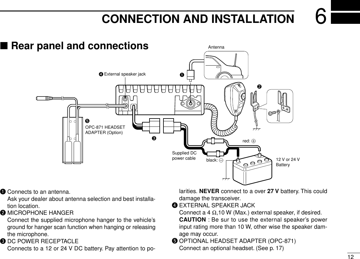
![■Panel descriptionqTUNING [DIAL(TS)]➥Changes the operating frequency; memory channel inmemory mode; set mode contents in set mode, etc.➥Push to toggle the dimmer control ON or OFF.➥Push and hold for 1 sec. to select the Tuning Step [TS]; 1MHz or 10 kHz are available. (p. 5)wFUNCTION DISPLAY (p. 3)Displays the operating frequency, memory channel name, etc.eVOLUME UP [Y] DOWN [Z]KEYAdjusts the audio output level.rLOUD SPEAKERFront mounted loud speaker.tPOWER SWITCH [POWER]Push and hold 500 m sec. to turn the power ON and OFF.➥The following functions are available at power ON as options:•Initial set mode (p. 10)11PANEL DESCRIPTIONV/MSCANPRI SQL!0qwertyuio](https://usermanual.wiki/ICOM-orporated/IC-A110.Manual/User-Guide-77826-Page-4.png)
![21PANEL DESCRIPTION•Cloning mode (p. 1d)ySQL SWITCH [SQL]➥Push to turn on the squelch adjust mode. (p. 6)➥Push and hold this switch for 1 sec. to turn ON/OFF the ex-ternal speaker output. (p. 4)uPRIORITY SWITCH [PRI]Push to select priority channel. (p. 11)•“Pr”appears on the display.iSCAN SWITCH [SCAN]➥Starts and stops the scan function:•VFO mode: VFO scan function.•Memory mode: Memory channel scan function. (p. 6)➥Push and hold this switch for 5 sec. to set the displayedchannel as a memory lock-out channel. (p. 8)•“LOCK OUT”appears on the display.oVFO/MEMORY SWITCH [V/M]/[MW]➥Push to toggle the VFO mode or the Memory mode. (p. 4)• “X”and memory channel number appear when memory modeis selected.• The transceiver has 20 memory channels.➥When VFO mode is selected;•Push and hold this switch for 5 sec. to program the VFOfrequency to memory channel. (p. 8)➥When Memory mode is selected;•Push and hold this switch for 5 sec. to turn the “Memoryname write mode”ON.!0 MICROPHONE CONNECTORConnects the supplied microphone or optional.NEVER connect other microphones. The pin assignmentsmay be different and the transceiver may be damaged.MICROPHONEThe supplied microphone has a PTT switch and a cradle. Thefollowing functions are available when the microphone istaken off from the hook or put back on hook:➥Automatic scan starts when putting on hook. (p. 7)➥Automatic scan stops when taken off hook. (p. 7)NOTE: Optional functions vary with transceiver version.In this manual, optional functions are indicated by“”Icon.Please contact your dealer for details.](https://usermanual.wiki/ICOM-orporated/IC-A110.Manual/User-Guide-77826-Page-5.png)
![31PANEL DESCRIPTION■Function displayqMEMORY MODE INDICATOR (p. 5)Appears when memory mode is selected.wDUALWATCH INDICATOR (p. 7)Indicates when the dualwatch function is activated.eSCAN INDICATOR (p. 8)Indicates when the scan function is selected.rBUSY INDICATOR (p. 6)“BUSY”appears when receiving a signal or when thesquelch is open. (p. 6)tTX INDICATOR (p. 5)Appears while transmitting.yFREQUENCY DISPLAY (p. 11)➥Shows the operating frequency.➥Shows the channel name when the memory name functionis selected. (p. 10)uVOLUME LEVEL INDICATORS➥Shows the AF volume level(while receiving).iSET MODE INDICATOR➥Appears when the Initial set mode is selected. (p. 12)!0 LOCK OUT INDICATOR➥Appears when the channel is set as a ‘LOCK OUT’chan-nel. (p. 10)!1 MEMORY CHANNEL INDICATOR➥Indicates the selected memory channel number➥‘Pr’appears when the priority channel is selected.*NOTE: The VFO/memory switch [V/M] and the memorywrite switch [M/W] functions may not be available de-pending on version.wq rt!1eoiuy](https://usermanual.wiki/ICOM-orporated/IC-A110.Manual/User-Guide-77826-Page-6.png)
![42BASIC OPERATION■Power ONqPush [POWER] to turn power ON.wOperate the transceiver as indicated in the following sec-tions.eSelect the desired memory channel (or VFO frequency)with the [V/M] keys.•When receiving a signal, appears and audio is emit-ted from the speaker.•Further adjustment of audio level may be necessary at this point.•Push [SQL] to adjust the squelch level. (p. 6)•Push and hold the tuning dial for 1 sec. to select the [TS], eachpush increments/decrements to the frequency are either 10 kHzor 1 MHz. (p. 7)rPush and hold [PTT] to transmit, then speak into the mi-crophone.•Transmit indicator lights.tRelease [PTT] to receive.■Channel selctionïVFO/Memory selectionqPush [V/M] to select memorymode or VFO mode.➥Rotate the dial to select a de-sired frequency/channel.wDuring memory mode opera-tion, push [V/M] key to trans-fer the memory contents toVFO.• Push [V/M] to select VFOmode.NOTE: Only frequency data is transferred even if the mem-ory channel has a memory name.ïExternal speaker output controlExternal speaker output can be turned OFF, if desired.qPush and hold [SQL] for 1 sec.wRotate the dial to select “SP OFF”.ePush [SQL] to turn to the previous mode.NOTE: This function avail-able external speaker only.](https://usermanual.wiki/ICOM-orporated/IC-A110.Manual/User-Guide-77826-Page-7.png)
![52BASIC OPERATION■Squelch functionThe transceiver has a noise squelch circuit to mute undesirednoise while receiving no signal.DSetting the squelch levelqPush [SQL] to turn the level adjusting mode ON.wTurn the tuning [DIAL] to select the squelch level.•‘SQ 01’is loose squelch and ‘SQ 25’is tight squelch. (Ini-tial level is ‘SQ 01’)•‘SQ 01’indicates that the squelch circuit is turned off.• “”appears on the display.ePush [SQL] to return to regular operation.■Side tone functionWhen using an optional headset, such as those from theDavid Clark Co. via the OPC-871 HEAD SET ADAPTOR, thetransceiver outputs your transmitted voice to the headset formonitoring. (p. 17)■LCD backlight controlThe backlight of the can be set OFF, Low or High.➥Push [DIAL] to toggle the backlight control; OFF, Low orHigh are available.■Dial select functionUse the dial select function to adjust the tuning behavior ofthe [DIAL] keys—use 1 MHz tuning when you want to changethe frequency in large increments; use regular tuning (25 kHzor 8.33* kHz) when you want to change the frequency insmaller increments.qPush [V/M] to select VFOmode.wPush and hold [DIAL(TS)] for1 sec. to select the desiredtuning increment.•1 MHz tuning or regulartuning steps can be se-lected. (see diagrams atright)ePush and hold [DIAL(TS)] for1 sec. to return to normal op-eration.NOTE: Large tuning steps should be used only when youwant to change the frequency in large increments. Pleaseselect regular tuning steps for normal operation.1 MHz tuning selectedRegular tuning selected](https://usermanual.wiki/ICOM-orporated/IC-A110.Manual/User-Guide-77826-Page-8.png)
![63SCAN OPERATION■Scan operationqPush [V/M] to select memory mode or VFO mode, if nec-essary.•“ ”appears on the memory mode.wMake sure the squelch level is set to the threshold point.• Set a squelch level (01 to 25) where the noise is muted.ePush [SCAN] to start scan.• To change the scan direction, turn [DIAL].•“SCAN (or P SCAN)“ flashes while scaning.rPush [SCAN] again to stop the scan.NOTE: Normal scan or Priority scan is pre-programmedby cloning. Please ask your dealer or system operator fordetails.ïNORMAL SCAN•Memory lock scanRepeatedly scans memorychannels except skip (lockout)channels.•VFO scanRepeatedly scans allfrequencies over the entirband.Scan step is minimum channelspacing. (eg 25 kHz or 8.33kHz)ïPRIORITY SCAN•Priority memory scanWhile scaning on a memorymode, priority watch checksfor a signal on the selectedpriority channel every 250 msec except lockout channel.MRMch 2*Mch 1Mch 3Mch 20250 msec. *: Lockout chSKIP ScanJumpStart highestfrequencylowestfrequencyPrioritychMch 2*Mch 1Mch 3Mch 20250 msec. 250 msec.SKIP*: Lockout ch](https://usermanual.wiki/ICOM-orporated/IC-A110.Manual/User-Guide-77826-Page-9.png)
![73SCAN OPERATION■On–hook scanOn–hook scan (Hanger scan) is available when taking the mi-crophone from its hanger (off–hook) and /or returning it intothe hanger (on–hook).qPush [SCAN] to start scanning.wWhen receiving a signal, scan pauses until the signal dis-appears.➥•You can converse by taking the microphone from thehook.ePlace the microphone on the hook to restart scanning.rScan restarts 2 sec. after the signal disappears even if youdid not converse the station.When you take the microphone during the scan operation.➥•In VFO scan; scan resumes promptly to frequency.➥•In memory scan; scan resumes promptly to memorychannel.➥•In priority memory scan; scan resumes to priority channel, NOTE: Be sure to connect the supplied microphonehanger to the vehicle’s ground for on/off hook microphonefunctions.(p. 12)■DualwatchDualwatch monitors priority channel while you are receivingan other channel (VFO or memory channel).•If a signal is received on pri-ority channel, dualwatchpauses on priority channeluntil the signal dissappears.•To transmit on the selectedchannel during dualwatch,push and hold PTT.ïïOperationqSelect the desired operating channel (VFO or Memorychannel).wPush and hold [PRI] for 1 sec. to start dualwatch.‘P’blinks during dualwatch.eTo cancel dualwatch, push [PRI] again.VFOfrequencyormemory channelPrioritychannel5 sec.250 msec.](https://usermanual.wiki/ICOM-orporated/IC-A110.Manual/User-Guide-77826-Page-10.png)
![84MEMORY PROGRAMMINGDSetting lockout channelsIn order to speed up the scan interval, you can set memorychannels you don’t wish to be scanned as lockout channels.qPush [V/M] to select memory mode, if necessary.•“ ”appears.wTurn the [DIAL] to select a memory channel to set as alockout channel.ePush [SCAN] for 5 sec. to toggle the lockout settingON/OFF.•“LOCK OUT”appears when thechannel is set as a lockoutchannel.MR■Programming a memorychannelThe transceiver has 20 memory channels for storage of often-used frequencies.qPush [V/M] to select VFOmode, if necessary.wTurns the [DIAL] to select thedesired frequency.• Push [DIAL/TS] one or moretimes to use the dial selectfunction, if desired.ePush [V/M] for 5 sec. to entermemory programming mode.•“ ” and memory channelnumber appear.rTurn the [DIAL] to select thedesired memory channelnumber.tPush [V/M] for 1 sec. to pro-gram the information into thechannel and return to VFOmode.•Push [SQL] for 1 sec. to clearthe memory information.MR*NOTE: The VFO/memory switch [V/M] and the memorywrite switch [M/W] functions may not be available de-pending on version.Memory channel 8 is setas lockout channel.](https://usermanual.wiki/ICOM-orporated/IC-A110.Manual/User-Guide-77826-Page-11.png)
![94MEMORY PROGRAMMING■Memory namesïProgramming memory namesqSelect the memory channel to be programmed:➥Push [V/M] to select memory mode.➥Turns [DIAL] to select the memory channel.wPush [V/M] for 5 sec. to enter memory name writing mode.•The first character of the name flashes.eTurns the [DIAL] as many times as necessary to enter thedesired name.•To erase a character, overwrite with a space (displayed as _).•To move the cursor forwards or backwards, use [Y] or [Z].•Push [SQL] for 2 sec. to erase all characters.rPush [SCAN/MW] for 2 sec. to input the set name.•Flashing stops.•Memory channels can be programmed with names of up to 7characters in length.•When no name is programmed, the display shows the operatingfrequency.NOTE: •Push PTT switch to abort the programming memoryname.•The following characters can be used in names:➥0 to 9,A to Z (capitals), (space), $,%,’,(,),✽,+,“ ,”,–,/,<,=,>,?,@,[,\,],^,_ and `.V/Mfor 5 sec.V/Mfor 1 sec.+or[EXAMPLE]: Setting the name to “ TOWER 2”](https://usermanual.wiki/ICOM-orporated/IC-A110.Manual/User-Guide-77826-Page-12.png)
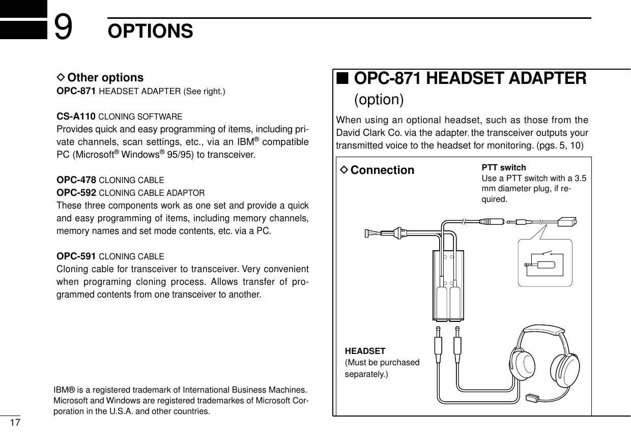
![5OTHER FUNCTIONS10■Initial set modeInitial set mode is accessed at power ON and allows you toset seldom-changed settings. In this way you can “customize”transceiver operations to suit your preferences and operatingstyle.DEntering initial set modeqWhile pushing and holding [V/M] + [TS(DIAL)], push[POWER] sw to turn power ON.•The transceiver enters initial set mode and “MN”, “BP”, “ST”or“PR”(p. 11) appears on the display.wPush [TS(DIAL)] to select thedesired item as describedbelow and at right.eTurn [DIAL(TS)] to select thedesired condition.rPush [SCAN] to exit initial setmode and select the previousoperating mode.DMemory namesThis item allows you to display a memory name instead of fre-quency.•When a memory channel has not been programmed with aname, frequency indication appears instead.DBeep tones ON/OFFConfirmation beep tones nor-mally sound when you push akey. These can be turned ON orOFF as you prefer.DSide tones ON/OFFWhen using an optional headsetsuch as those from the DavidClark Co. via the adapter, thetransceiver outputs your trans-mitted voice to the headset formonitoring.•Optional OPC-871 HEADSETADAPTER is required.](https://usermanual.wiki/ICOM-orporated/IC-A110.Manual/User-Guide-77826-Page-13.png)
![OTHER FUNCTION511DPriority channelThe priority channel is used to store your most often-usedchannel for quick recall. In addition the priority channel ismonitored during priority scan modes. The default setting forthe priority channel will differ depending on pre-programming.➥Push [PRI] to toggle the prioritychannel mode or previousmode.•Setting the priority channelqWhile pushing and holding[V/M] and [DIAL(TS)], push[POWER] to turn the powerON.• The transceiver enters initial setmode.wPush [TS(DIAL)] to select thepriority channel set mode.eSelect the desired channelnumber as a priority channel orOFF with [DIAL].rPush [POWER] to turn powerOFF.NEVER select the blank memory channel as the prioritychannel. In such case priority automatically sets to OFF posi-tion.](https://usermanual.wiki/ICOM-orporated/IC-A110.Manual/User-Guide-77826-Page-14.png)
![147CLONINGDData cloning Cloning allows you to quickly and easilytransfer the programmed contents from one transceiver toanother transceiver, or, data from PC to a transceiver usingthe optional CS-A110 cloning software.DTransceiver to transceiver cloning qConnect the OPC-591 CLONING CABLE with adapter plugs tothe [MIC] jack of the master and slave transceivers.•The master transceiver is used to send data to the slave trans-ceiver.wWhile pushing and holding [Y] + [Z] + [V/M], push[POWER] ON to enter cloning mode (master transceiveronly—power ON only for slave transceiver).•“CLONE”appears and thetransceivers enter the clonestandby condition.ePush [POWER] on the mas-ter transceiver.•“CL-OUT”appears in themaster transceiver’s display.•“CL-IN”appears automati-cally in the slave trans-ceiver’s display.eWhen cloning is finished, turnpower OFF, then ON again toexit cloning mode.DCloning using PCData can be cloned to and from a PC (IBM compatible) usingthe optional CS-A110 CLONING SOFTWARE and the optional OPC-478 CLONING CABLE+ OPC-592 CLONING CABLE ADAPTER. Consult theCS-A110 CLONING SOFTWARE HELP message for details.DCloning errorWhen the display at right ap-pears, a cloning error has oc-curred.In this case, both transceivers automatically return to theclone standby condition and cloning must be repeated.]](https://usermanual.wiki/ICOM-orporated/IC-A110.Manual/User-Guide-77826-Page-17.png)