ICOM orporated IC-A110 VHF-AM Aircraft Band Transceiver User Manual
ICOM Incorporated VHF-AM Aircraft Band Transceiver
UserManual.wiki
>
ICOM orporated
>
IC-A110 User Manual
>
User Manual
Contents
1.
Manual
2.
User Manual
User Manual
Navigation menu
Upload a User Manual
Namespaces
Wiki Guide
HTML
PDF
Info
Views
User Manual
Discussion / Help
Navigation
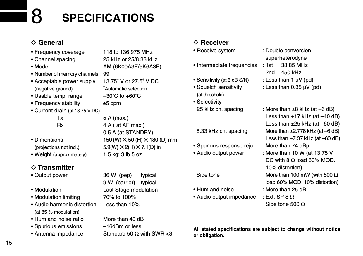
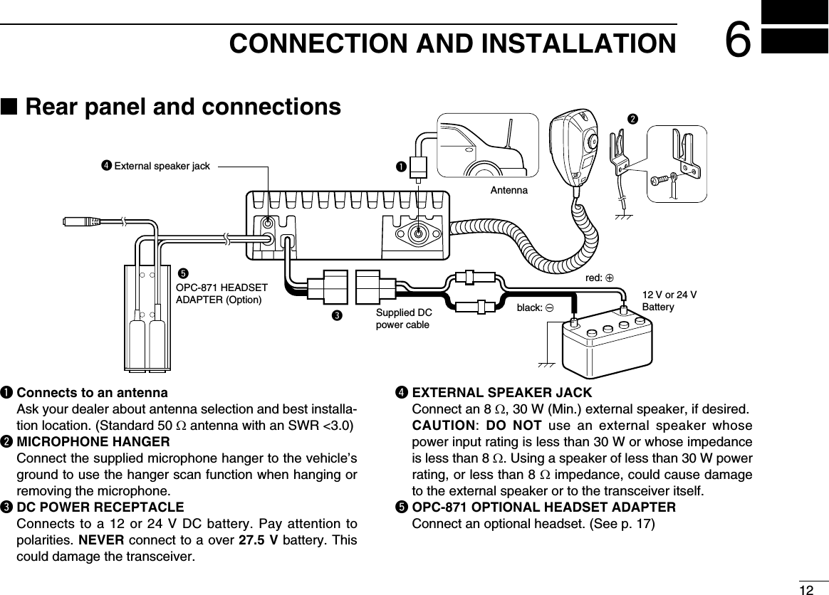
![DO NOT push [PTT] when not actually desiring to trans-mit.DO NOT use or place the transceiver in direct sunlight or in areas with temperatures below –30°C (–22°F) or above +60°C (+140°F).DO NOT place the transceiver in excessively dusty envi-ronments.DO NOT place the transceiver against walls. This will ob-struct heat dissipation.DO NOT use harsh solvents such as benzine or alcohol to clean the transceiver, as they can damage the trans ceiver’s surfaces.BE CAREFUL! The transceiver will become hot when op-erating continuously for long periods of time.CAUTIONSiiFCC caution: Changes or modifications to this transceiver, not expressly approved by Icom Inc., could void your authority to operate this transceiver under FCC regulations.TABLE OF CONTENTSFOREWORD .......................................................................................... iEXPLICIT DEFINITIONS ........................................................................ iCAUTIONS ............................................................................................. iTABLE OF CONTENTS ......................................................................... ii1 PANEL DESCRIPTION ............................................................... 1–3 ■ Panel description ..................................................................... 1–2 ■ Function display ........................................................................... 32 BASIC OPERATION ................................................................... 4–5 ■ Power ON .................................................................................... 4 ■ Channel selection ......................................................................... 4 ■ Squelch function ........................................................................... 5 ■ Side tone function ......................................................................... 5 ■ LCD backlight control.................................................................... 5 ■ Dial select function........................................................................ 53 SCAN OPERATION .................................................................... 6–7 ■ Scan operation ............................................................................ 6 ■ ON-hook scan .............................................................................. 7 ■ Dualwatch .................................................................................... 74 MEMORY PROGRAMMING ....................................................... 8–9 ■ Programming a memory channel.................................................. 8 ■ Memory names ............................................................................. 95 OTHER FUNCTIONS .............................................................. 10–11 ■ Initial Set mode .......................................................................... 106 CONNECTION AND INSTALLATION .................................... 12–13 ■ Rear panel and connections ...................................................... 12 ■ Mounting .................................................................................... 13 ■ Supplied accessories .................................................................. 137 CLONING ...................................................................................... 14 8 SPECIFICATIONS .................................................................. 15–169 OPTIONS ................................................................................. 17–18 ■ OPC-871 Headset adapter ......................................................... 17 ■ Other options .............................................................................. 1710 FOR CLASS B UNINTENTIONAL RADIATORS ......................... 1911 SAFETY TRAINING INFORMATION ........................................... 20](https://usermanual.wiki/ICOM-orporated/IC-A110.User-Manual/User-Guide-1419976-Page-3.png)
![■ Panel descriptionq TUNING [DIAL] [TS](DIAL)➥ Changes the operating frequency; memory channel in the Memory mode; set mode contents in the Set mode, etc.➥ Push to toggle the dimmer control OFF, Low or High.➥ Hold down for 1 second to select the Tuning Step [TS]; 1 MHz or 10 kHz are selectable. (p. 5)w FUNCTION DISPLAY (p. 3)Displays the operating frequency, memory channel name, etc.e VOLUME UP [Y] DOWN [Z] KEYAdjusts the audio output level.r LOUD SPEAKERFront mounted loud speaker.t POWER SWITCH [POWER]Hold down 0.5 seconds to turn the power ON or OFF.• At Power ON, the Initial Set mode (p. 10) or the Cloning mode (p. 14) can optionally be selected.11PANEL DESCRIPTIONV/MSCANPRI SQL!0qwertyuio](https://usermanual.wiki/ICOM-orporated/IC-A110.User-Manual/User-Guide-1419976-Page-4.png)
![21PANEL DESCRIPTIONy SQL SWITCH [SQL]➥ Push to turn ON the squelch adjust mode. (p. 6)➥ Hold down this switch for 1 second to turn the both in-ternal and external speaker output ON or OFF. (p. 4)u PRIORITY SWITCH [PRI]Push to select the priority channel. (p. 11) • “Pr” appears on the display.i SCAN SWITCH [SCAN]➥ Starts and stops the scan function:• VFO mode: VFO scan function. (p. 6)• Memory mode: Memory channel scan function. (p. 6)➥ Hold down this switch for 5 seconds to set the displayed channel as a memory lockout channel. (p. 8)• “LOCK OUT” appears on the display.o VFO/MEMORY SWITCH [V/M] [MW](V/M)➥ Push to toggle between the VFO mode and the Memory mode. (p. 4)• “X” and memory channel number appear when the Mem-ory mode is selected.• The transceiver has 99 memory channels.➥ When the VFO mode is selected;• Hold down this switch for 5 seconds to enter the VFO fre-quency into the memory channel. (p. 8)➥ When the Memory mode is selected;• Hold down this switch for 5 seconds to turn ON the “Memory name write mode.”!0 MICROPHONE CONNECTORConnects to the supplied microphone or optional.NEVER connect other microphones. The pin assignments may be different and the transceiver may be damaged.MICROPHONEThe supplied microphone has a PTT switch and a cradle. The following functions are available when the microphone is taken off the hook or put back on the hook:➥ Automatic scan starts when the microphone is put ON Hook. (p. 7)➥ Automatic scan stops when the microphone is taken OFF Hook. (p. 7)NOTE: Optional functions vary with transceiver version. In this manual, optional functions are indicated by an “” Icon. Please contact your dealer for details.](https://usermanual.wiki/ICOM-orporated/IC-A110.User-Manual/User-Guide-1419976-Page-5.png)
![31PANEL DESCRIPTION■ Function displayq MEMORY MODE INDICATOR (p. 5)Appears when the Memory mode is selected.w DUALWATCH INDICATOR (p. 7)Appears when the dualwatch function is activated.e SCAN INDICATOR (p. 8)Appears when the scan function is selected.r BUSY INDICATOR (p. 6)“BUSY” appears when receiving a signal or when the squelch is open. (p. 6)t TX INDICATOR (p. 5)Appears while transmitting.y FREQUENCY DISPLAY (p. 11)➥Shows the operating frequency. ➥ Shows the channel name when the memory name func-tion is selected. (p. 10) u VOLUME LEVEL INDICATORS➥ Shows the AF volume level (while receiving).i SET MODE INDICATOR➥ Appears when the Initial Set mode is selected. (p. 12)o LOCK OUT INDICATOR➥ Appears when the channel is set as a ‘LOCK OUT’ channel. (p. 8)!0 MEMORY CHANNEL INDICATOR➥ Displays the selected memory channel number➥ ‘Pr’ appears when the priority channel is selected.*NOTE: The VFO/memory switch [V/M] and the memory write switch [MW](V/M) functions may not be available, depending on the version.wqrt!1eoiuy](https://usermanual.wiki/ICOM-orporated/IC-A110.User-Manual/User-Guide-1419976-Page-6.png)
![42BASIC OPERATION■ Power ONq Push [POWER] to turn ON the power.w Operate the transceiver as described in the following sec-tions.e Select the desired memory channel (or VFO frequency) with the [V/M] keys. • When receiving a signal, appears and audio is heard from the speaker. • Further adjustment of the audio level may be necessary at this point. • Push [SQL] to adjust the squelch level. (p. 6) • Hold down [TS](DIAL) for 1 second to select the tuning step. 1 MHz or 10 kHz are selectable. (p. 7)r Hold down [PTT] to transmit, then speak into the micro-phone at your normal voice level. • Transmit indicator lights.t Release [PTT] to receive.■ Channel selectionï VFO/Memory selectionPush [V/M] to select the Memory mode or the VFO mode.➥ Rotate [DIAL] to select a de-sired frequency or channel.ï External speaker output controlExternal speaker output can be turned OFF, if desired.q Hold down [SQL] for 1 second.w Rotate [DIAL] to select “SP OFF”.e Push [SQL] to return to the previous mode. NOTE: This function is avail-able for both internal and ex-ternal speakers.](https://usermanual.wiki/ICOM-orporated/IC-A110.User-Manual/User-Guide-1419976-Page-7.png)
![52BASIC OPERATION■ Squelch functionThe transceiver has a noise squelch circuit to mute undesired noise while receiving no signals.D Setting the squelch levelq Push [SQL] to turn ON the level adjusting mode.w Rotate [DIAL] to select the squelch level. • ‘SQ 01’ is loose squelch and ‘SQ 25’ is tight squelch. (Initial level is ‘SQ 01’) • ‘SQ 01’ indicates that the squelch circuit is turned off. • “ ” appears on the display.e Push [SQL] to return to regular operation.■ Side tone functionWhen using an optional headset, such as those from the David Clark Co. using the OPC-871 HEAD SET ADAPTER, the transceiver outputs your transmitted voice to the headset for monitoring. (p. 17)■ LCD backlight controlThe backlight of the LCD can be set to OFF, Low or High.➥ Push [DIAL] to toggle the backlight control; OFF, Low or High are selectable.■ Dial select function Use the dial select function to adjust the tuning steps of the [DIAL] keys. Use 1 MHz tuning when you want to change the frequency in large increments; use regular tuning (25 kHz or 8.33 kHz) when you want to change the frequency in smaller increments.q Push [V/M] to select VFO mode.w Hold down [TS](DIAL) for 1 second to select the desired tuning increment. • 1 MHz tuning or regular tuning steps can be se-lected. (see the diagrams to the right)e Hold down [TS](DIAL) for 1 second to return to normal operation. NOTE: Large tuning steps should be used only when you want to change the frequency in large increments. Please select regular tuning steps for normal operation.1 MHz tuning selectedRegular tuning selected](https://usermanual.wiki/ICOM-orporated/IC-A110.User-Manual/User-Guide-1419976-Page-8.png)
![63SCAN OPERATION■ Scan operation q Push [V/M] to select the Memory mode or the VFO mode, if necessary. • “MR” appears when in the Memory mode.w Make sure the squelch level is set to the threshold point. • Set the squelch level (01 to 25) where the noise is just muted.e Push [SCAN] to start the scan. • To change the scan direction, turn [DIAL]. • “SCAN (or P SCAN)” ashes while scanning.r Push [SCAN] again to stop the scan. NOTE: Normal scan or Priority scan is pre-programmed by cloning. Please ask your dealer or system operator for details.ï NORMAL SCAN• Memory lock scanRepeatedly scans memory channels except skip (lockout) channels.• VFO scanRepeatedly scans all frequencies over the entire band. Scan step is minimum channel spacing. (eg 25 kHz or 8.33 kHz)ï PRIORITY SCAN• Priority memory scanWhile scanning in the Memory mode, priority watch checks for a signal on the selected priority channel every 250 msec., and skips the lockout channel(s).Mch 2*Mch 1Mch 3Mch 99250 msec.SKIP*: Lockout ch ScanJumpStart highestfrequencylowestfrequencyPrioritychMch 2*Mch 1Mch 3Mch 99250 msec. 250 msec.SKIP*: Lockout ch](https://usermanual.wiki/ICOM-orporated/IC-A110.User-Manual/User-Guide-1419976-Page-9.png)
![73SCAN OPERATION■ ON–Hook scan An ON–Hook scan (Hanger scan) stops when taking the microphone off its hanger (OFF–Hook) and resumes when putting it back on the hanger (ON–Hook).➥ Push [SCAN] to start scanning. • When a signal is received, the scan pauses until the signal dis-appears. • The scan resumes 2 seconds after the signal disappears, unless you pushed [PTT] and transmitted.• Take the microphone off the hanger to stop the scan.• Put the microphone back on the hanger to resume scan-ning.When you take the microphone OFF Hook during the scan operation.• In VFO scan; the scan stops on the last frequency that was scanned.• In memory scan; the scan stops on the last memory channel that was scanned.• In priority memory scan; the scan stops on the priority channel. NOTE: Be sure to connect the supplied microphone hanger to the vehicle’s ground for ON and OFF Hook mi-crophone functions. (p. 12)■ DualwatchDualwatch monitors the priority channel while you are receiving another channel (VFO or memory channel).• If a signal is received on the priority channel, dualwatch pauses on the priority chan-nel until the signal disap-pears.• To transmit on the selected channel during dualwatch, hold down [PTT]. See page 11 for details of the priority channel setting.ï Operationq Select the desired operating channel (VFO or Memory channel).w Hold down [PRI] for 1 second to start dualwatch. ‘P’ blinks during dualwatch.e To cancel dualwatch, push [PRI] again.VFOfrequencyormemory channelPrioritychannel5 sec.250 msec.](https://usermanual.wiki/ICOM-orporated/IC-A110.User-Manual/User-Guide-1419976-Page-10.png)
![84MEMORY PROGRAMMINGD Setting lockout channelsIn order to speed up the scan periods, you can set memory channels you don’t wish to be scanned as lockout channels.q Push [V/M] to select the Memory mode, if necessary. • “MR” appears.w Rotate [DIAL] to select a memory channel to set as a lock-out channel.e Hold down [SCAN] for 5 sec-onds to toggle the lockout setting ON or OFF. • “LOCK OUT” appears when the channel is set as a lockout channel.The transceiver has 99 memory channels for storage of of-ten-used frequencies.q Push [V/M] to select the VFO mode, if necessary.w Rotate [DIAL] to select the desired frequency. • Push [TS](DIAL) one or more times to use the dial select function, if desired.e Hold down [MW](V/M) for 5 seconds to enter memory programming mode. • “MR” and memory channel number appear.r Rotate [DIAL] to select the desired memory channel number.t Hold down [MW](V/M) for 1 second to program the infor-mation into the channel and return to VFO mode. • To clear the memory informa-tion, hold down [SQL] for 1 sec-ond.MRMRMRBUSYSKIP50*NOTE: The VFO/memory switch [V/M] and the memory write switch [MW] functions may not be available, de-pending on version.Memory channel 8 is set as a lockout channel.■ Programming a memory channel](https://usermanual.wiki/ICOM-orporated/IC-A110.User-Manual/User-Guide-1419976-Page-11.png)
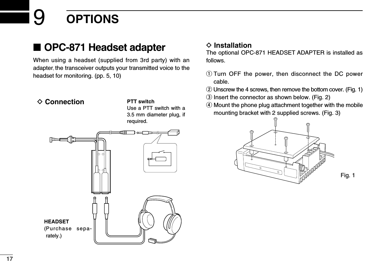
![94MEMORY PROGRAMMING■ Memory names ï Programming memory namesq Select the memory channel to be programmed: ➥ Push [V/M] to select the Memory mode. ➥ Rotate [DIAL] to select the memory channel.w Hold down [MW](V/M) for 5 seconds to enter memory name writing mode. • The rst digit blinks.e Repeatedly rotate [DIAL] to select the desired character. • To erase a character, overwrite with a space (displayed as _). • To move the cursor forwards or backwards, push [Y] or [Z]. • Hold down [SQL] for 2 seconds to erase all characters.r Hold down [MW](V/M) for 1 second to input the entered name. • The character stops blinking. • Memory channels can be programmed with names of up to 7 characters in length. • When no name is programmed, the display shows the operating frequency. NOTE: Push [PTT] to cancel the memory name programming.• The following characters can be used in names: ➥ 0 to 9, A to Z (capitals), (space), $, %, ’, (, ), ✽, +, “ , ”, –, /, <, =, >, ?, @, [, \, ], ^, _ and `.V/Mfor 5 sec.V/Mfor 1 sec.+or[EXAMPLE]: Setting the name to “TOWER 2”](https://usermanual.wiki/ICOM-orporated/IC-A110.User-Manual/User-Guide-1419976-Page-12.png)
![5OTHER FUNCTIONS10■ Initial Set mode The Initial Set mode is entered at Power ON and allows you to set seldom-changed settings. In this way you can “customize” the transceiver operations to suit your preferences and operating style.D Entering Initial Set modeq While holding down [V/M] + [TS](DIAL), push [POWER] to turn ON the power. • The transceiver enters the Initial Set mode and “MN”, “BP”, “ST” or “PR” (p. 11) appears on the display.w Push [TS](DIAL) to select the desired item as described below and to the right.e Rotate [DIAL] to select the de-sired option or setting.r Push [SCAN] to exit the Initial Set mode and return to the pre-vious operating mode.D Memory namesThis item allows you to display a memory name instead of the frequency.• When a memory channel has not been programmed with a name, the frequency appears instead.D Beep tones ON/OFFConfirmation beep tones normally sound when you push a key. These can be turned ON or OFF, as you prefer.D Side tones ON/OFFWhen using an optional head-set such as those from the David Clark Co. using an the adapter, the transceiver outputs your trans-mitted voice to the headset for monitoring.• Optional OPC-871 HEADSET ADAPTER is required.](https://usermanual.wiki/ICOM-orporated/IC-A110.User-Manual/User-Guide-1419976-Page-13.png)
![OTHER FUNCTION511D Priority channel The priority channel is used to store your most often-used channel for quick recall. In addition, the priority channel is monitored during priority scan modes. The default setting for the priority channel will differ, depending on pre-program-ming.➥ Push [PRI] to toggle the prior-ity channel mode or the previ-ous mode.• Setting the priority channelq While holding down [V/M] and [TS](DIAL), push [POWER] to turn ON the power. • The transceiver enters the Initial Set mode.w Push [TS](DIAL) to select the priority channel Set mode.e Rotate [DIAL] to select the desired channel number as a priority channel or OFF.r Hold down [POWER] to turn OFF the power.NEVER select the blank memory channel as the priority channel. In such a case the priority function is automatically set to the OFF position.](https://usermanual.wiki/ICOM-orporated/IC-A110.User-Manual/User-Guide-1419976-Page-14.png)
![147CLONINGD Data cloning Cloning allows you to quickly and easily transfer the programmed contents from one transceiver to another transceiver or data from a PC to a transceiver using the optional CS-A110/EURO cloning software.D Transceiver to transceiver cloning q Connect the OPC-591 CLONING CABLE with adapter plugs to the [MIC] jack of the master and sub-transceivers. • The master transceiver is used to send data to the sub-trans-ceiver.w While holding down [Y] + [Z] + [V/M], push [POWER] to enter cloning mode (master transceiver only —power ON only for sub-transceiver). • “CLONE” appears and the transceivers enter the clone standby mode.e Push [POWER] on the mas-ter transceiver. • “CL-OUT” appears in the master transceiver’s dis-play. • “CL-IN” appears automati-cally in the sub-transceiver’s display.e When cloning is finished, turn power OFF, then ON again to exit the cloning mode.D Cloning using PCData can be cloned to and from a PC using the optional CS-A110/EURO CLONING SOFTWARE and the optional OPC-478 CLONING CABLE+ OPC-592 CLONING CABLE ADAPTER. Consult the CS-A110/EURO CLONING SOFTWARE HELP message for details.D Cloning errorWhen the display to the right appears, a cloning error has oc-curred.In this case, both transceivers automatically return to the clone standby mode and cloning must be repeated.]](https://usermanual.wiki/ICOM-orporated/IC-A110.User-Manual/User-Guide-1419976-Page-17.png)