ICOM orporated IC-A110 VHF-AM Aircraft Band Transceiver User Manual IC A110
ICOM Incorporated VHF-AM Aircraft Band Transceiver IC A110
Contents
- 1. Manual
- 2. User Manual
Manual

iA110
VHF AIR BAND TRANSCEIVER
INSTRUCTION MANUAL
This device complies with Part 15 of the
FCC Rules. Operation is subject to the
condition that this device does not cause
harmful interference.

i
FOREWORD
READ ALL INSTRUCTIONS carefully and completely
before using the transceiver.
SAVE THIS INSTRUCTION MANUAL —This in-
struction manual contains important operating instructions for
the IC-A110.
EXPLICIT DEFINITIONS
The explicit definitions below apply to this instruction manual.
CAUTIONS
RWARNING! NEVER operate the transceiver with a
headset or other audio accessories at high volume levels.
Hearing experts advise against continuous high volume op-
eration. If you experience a ringing in your ears, reduce the
volume level or discontinue use.
NEVER connect the transceiver to an AC outlet or to a
power source of more than 27 V DC. Such a connection will
damage the transceiver.
NEVER connect the transceiver to a power source that is
DC fused at more than 5 A. Accidental reverse connection will
be protected by this fuse, higher fuse values will not give any
protection against such accidents and the transceiver will be
ruined.
DO NOT push the PTT when not actually desiring to trans-
mit.
DO NOT operate the transceiver near unshielded electrical
blasting caps or in an explosive atmosphere.
AVOID using or placing the transceiver in direct sunlight or
in areas with temperatures below –30°C (–22°F) or above
WORD DEFINITION
RWARNING Personal injury, fire hazard or electric shock
may occur.
CAUTION Equipment damage may occur.
NOTE If disregarded, inconvenience only. No risk
of personal injury, fire or electric shock.
FCC caution: Changes or modifications to this transceiver, not
expressly approved by Icom Inc., could void your authority to
operate this transceiver under FCC regulations.

ii
+60°C (+140°F).
DO NOT place unit in a non-secure place to avoid inad-
vertent use by children.
DO NOT connect the transceiver to a power source using
reverse polarity. This connection will not only blow fuses but
also may damage the transceiver.
AVOID placing the transceiver in excessively dusty enviro-
ments.
AVOID placing the transceiver against walls. This will ob-
struct heat disspation.
AVOID the use of chemical agents such as benzine or al-
cohol when cleaning, as they damage the transceiver sur-
faces.
BE CAREFUL! The transceiver will become hot when
operating continuously for long periods.
TABLE OF CONTENTS
FOREWORD ........................................................................................... i
EXPLICIT DEFINITIONS ......................................................................... i
CAUTIONS .............................................................................................. i
TABLE OF CONTENTS .......................................................................... ii
1 PANEL DESCRIPTION ............................................................... 1–3
■Panel description ............................................................................. 1–2
■Function display .................................................................................... 3
2 BASIC OPERATION ................................................................... 4–5
■Power ON ............................................................................................. 4
■Channel selection.................................................................................. 4
■Squelch function.................................................................................... 5
■Side tone function.................................................................................. 5
■LCD backlight control............................................................................. 5
■Dial select function ................................................................................ 5
3 SCAN OPERATION ................................................................... 6 –7
■Scan operation ..................................................................................... 6
■On-hook scan ....................................................................................... 7
■Dualwatch ............................................................................................. 7
4 MEMORY PROGRAMMING ...................................................... 8 –9
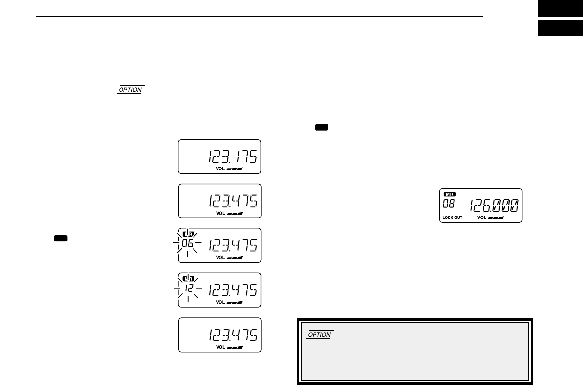
■Programming a memory channel .......................................................... 8
■Memory names...................................................................................... 9
5 OTHER FUNCTIONS ............................................................... 10-11
■Initial set mode .............................................................................. 10-11
6 CONNECTION AND INSTALLATION .................................... 12 –13
■Rear panel and connections ............................................................... 12
■Mounting ............................................................................................. 13
■Supplied accessories........................................................................... 13
7 CLONING ...................................................................................... 14
8 SPECIFICATIONS ............................................................. 15-16
9 OPTIONS............................................................................ 17-18
■OPC-871 HEADSET ADAPTER..................................................... 17-18
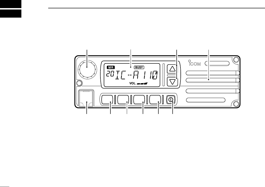
■Panel description
qTUNING [DIAL(TS)]
➥Changes the operating frequency; memory channel in
memory mode; set mode contents in set mode, etc.
➥Push to toggle the dimmer control ON or OFF.
➥Push and hold for 1 sec. to select the Tuning Step [TS]; 1
MHz or 10 kHz are available. (p. 5)
wFUNCTION DISPLAY (p. 3)
Displays the operating frequency, memory channel name, etc.
eVOLUME UP [Y] DOWN [Z]KEY
Adjusts the audio output level.
rLOUD SPEAKER
Front mounted loud speaker.
tPOWER SWITCH [POWER]
Push and hold 500 m sec. to turn the power ON and OFF.
➥The following functions are available at power ON as options:
•Initial set mode (p. 10)
1
1PANEL DESCRIPTION
V/M
SCAN
PRI SQL
!0
qwe
r
tyu
io

2
1
PANEL DESCRIPTION
•Cloning mode (p. 1d)
ySQL SWITCH [SQL]
➥Push to turn on the squelch adjust mode. (p. 6)
➥Push and hold this switch for 1 sec. to turn ON/OFF the ex-
ternal speaker output. (p. 4)
uPRIORITY SWITCH [PRI]
Push to select priority channel. (p. 11)
•“Pr”appears on the display.
iSCAN SWITCH [SCAN]
➥Starts and stops the scan function:
•VFO mode: VFO scan function.
•Memory mode: Memory channel scan function. (p. 6)
➥Push and hold this switch for 5 sec. to set the displayed
channel as a memory lock-out channel. (p. 8)
•“LOCK OUT”appears on the display.
oVFO/MEMORY SWITCH [V/M]/[MW]
➥Push to toggle the VFO mode or the Memory mode. (p. 4)
• “X”and memory channel number appear when memory mode
is selected.
• The transceiver has 20 memory channels.
➥When VFO mode is selected;
•Push and hold this switch for 5 sec. to program the VFO
frequency to memory channel. (p. 8)
➥When Memory mode is selected;
•Push and hold this switch for 5 sec. to turn the “Memory
name write mode”ON.
!0 MICROPHONE CONNECTOR
Connects the supplied microphone or optional.
NEVER connect other microphones. The pin assignments
may be different and the transceiver may be damaged.
MICROPHONE
The supplied microphone has a PTT switch and a cradle. The
following functions are available when the microphone is
taken off from the hook or put back on hook:
➥Automatic scan starts when putting on hook. (p. 7)
➥Automatic scan stops when taken off hook. (p. 7)
NOTE: Optional functions vary with transceiver version.
In this manual, optional functions are indicated by
“”Icon.
Please contact your dealer for details.
3
1PANEL DESCRIPTION
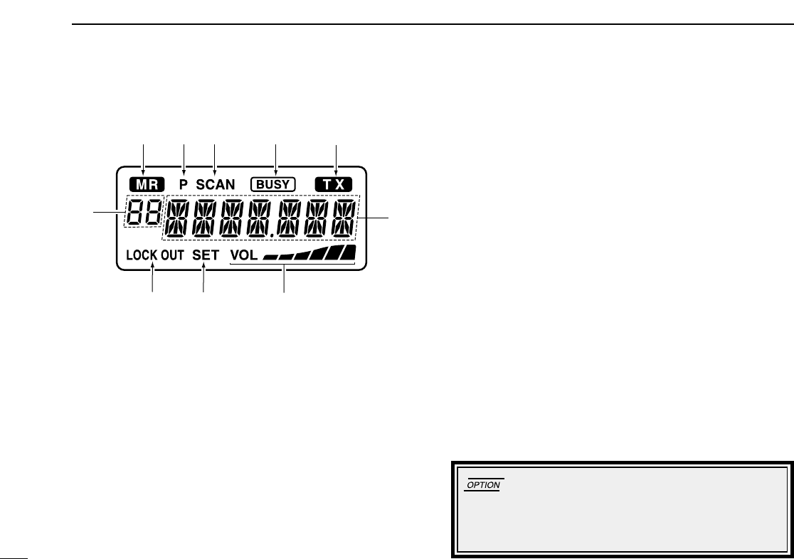
■Function display
qMEMORY MODE INDICATOR (p. 5)
Appears when memory mode is selected.
wDUALWATCH INDICATOR (p. 7)
Indicates when the dualwatch function is activated.
eSCAN INDICATOR (p. 8)
Indicates when the scan function is selected.
rBUSY INDICATOR (p. 6)
“BUSY”appears when receiving a signal or when the
squelch is open. (p. 6)
tTX INDICATOR (p. 5)
Appears while transmitting.
yFREQUENCY DISPLAY (p. 11)
➥Shows the operating frequency.
➥Shows the channel name when the memory name function
is selected. (p. 10)
uVOLUME LEVEL INDICATORS
➥Shows the AF volume level(while receiving).
iSET MODE INDICATOR
➥Appears when the Initial set mode is selected. (p. 12)
!0 LOCK OUT INDICATOR
➥Appears when the channel is set as a ‘LOCK OUT’chan-
nel. (p. 10)
!1 MEMORY CHANNEL INDICATOR
➥Indicates the selected memory channel number
➥‘Pr’appears when the priority channel is selected.
*NOTE: The VFO/memory switch [V/M] and the memory
write switch [M/W] functions may not be available de-
pending on version.
wq rt
!1
e
oiu
y
4
2
BASIC OPERATION
■Power ON
qPush [POWER] to turn power ON.
wOperate the transceiver as indicated in the following sec-
tions.
eSelect the desired memory channel (or VFO frequency)
with the [V/M] keys.
•When receiving a signal, appears and audio is emit-
ted from the speaker.
•Further adjustment of audio level may be necessary at this point.
•Push [SQL] to adjust the squelch level. (p. 6)
•Push and hold the tuning dial for 1 sec. to select the [TS], each
push increments/decrements to the frequency are either 10 kHz
or 1 MHz. (p. 7)
rPush and hold [PTT] to transmit, then speak into the mi-
crophone.
•Transmit indicator lights.
tRelease [PTT] to receive.
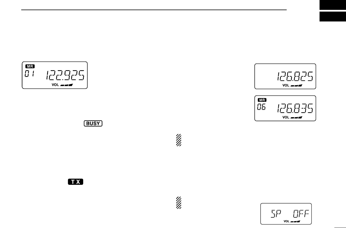
■Channel selction
ïVFO/Memory selection
qPush [V/M] to select memory
mode or VFO mode.
➥Rotate the dial to select a de-
sired frequency/channel.
wDuring memory mode opera-
tion, push [V/M] key to trans-
fer the memory contents to
VFO.
• Push [V/M] to select VFO
mode.
NOTE: Only frequency data is transferred even if the mem-
ory channel has a memory name.
ïExternal speaker output control
External speaker output can be turned OFF, if desired.
qPush and hold [SQL] for 1 sec.
wRotate the dial to select “SP OFF”.
ePush [SQL] to turn to the previous mode.
NOTE: This function avail-
able external speaker only.

5
2BASIC OPERATION
■Squelch function
The transceiver has a noise squelch circuit to mute undesired
noise while receiving no signal.
DSetting the squelch level
qPush [SQL] to turn the level adjusting mode ON.
wTurn the tuning [DIAL] to select the squelch level.
•‘SQ 01’is loose squelch and ‘SQ 25’is tight squelch. (Ini-
tial level is ‘SQ 01’)
•‘SQ 01’indicates that the squelch circuit is turned off.
• “”appears on the display.
ePush [SQL] to return to regular operation.
■Side tone function
When using an optional headset, such as those from the
David Clark Co. via the OPC-871 HEAD SET ADAPTOR, the
transceiver outputs your transmitted voice to the headset for
monitoring. (p. 17)
■LCD backlight control
The backlight of the can be set OFF, Low or High.
➥Push [DIAL] to toggle the backlight control; OFF, Low or
High are available.
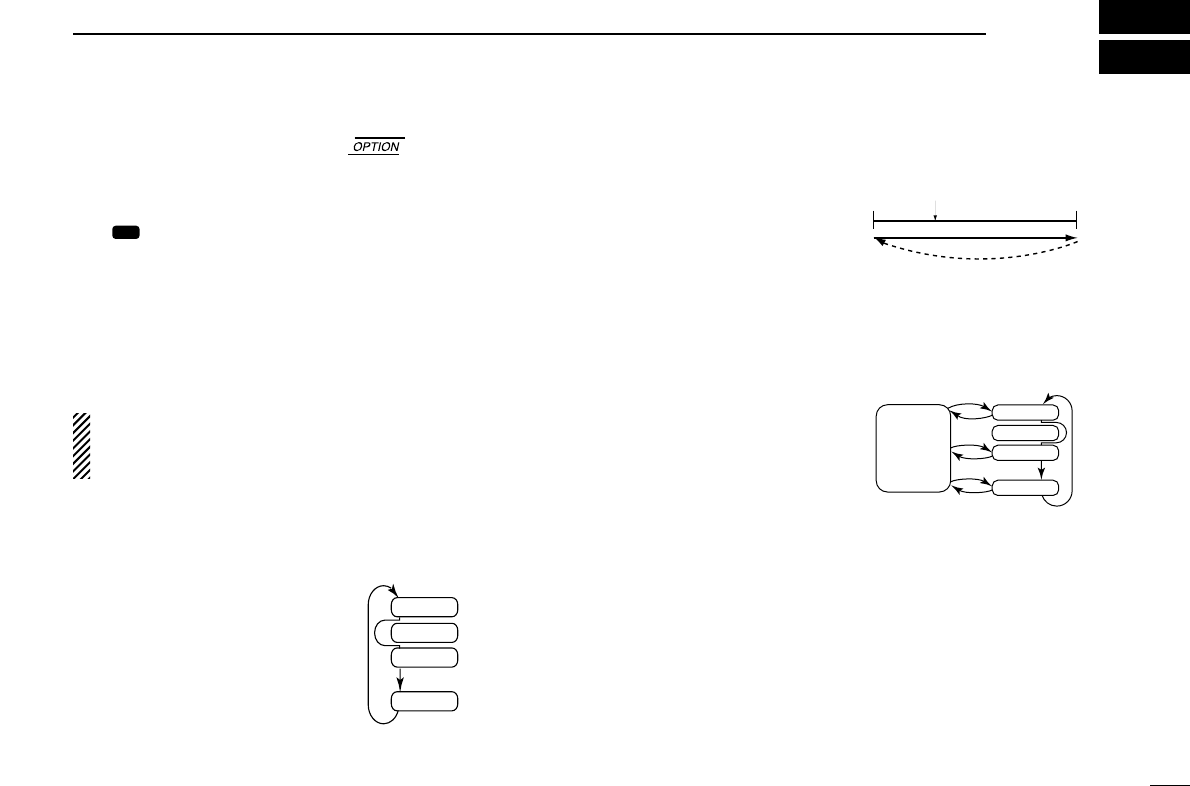
■Dial select function
Use the dial select function to adjust the tuning behavior of
the [DIAL] keys—use 1 MHz tuning when you want to change
the frequency in large increments; use regular tuning (25 kHz
or 8.33* kHz) when you want to change the frequency in
smaller increments.
qPush [V/M] to select VFO
mode.
wPush and hold [DIAL(TS)] for
1 sec. to select the desired
tuning increment.
•1 MHz tuning or regular
tuning steps can be se-
lected. (see diagrams at
right)
ePush and hold [DIAL(TS)] for
1 sec. to return to normal op-
eration.
NOTE: Large tuning steps should be used only when you
want to change the frequency in large increments. Please
select regular tuning steps for normal operation.
1 MHz tuning selected
Regular tuning selected
6
3
SCAN OPERATION
■Scan operation
qPush [V/M] to select memory mode or VFO mode, if nec-
essary.
•“ ”appears on the memory mode.
wMake sure the squelch level is set to the threshold point.
• Set a squelch level (01 to 25) where the noise is muted.
ePush [SCAN] to start scan.
• To change the scan direction, turn [DIAL].
•“SCAN (or P SCAN)“ flashes while scaning.
rPush [SCAN] again to stop the scan.
NOTE: Normal scan or Priority scan is pre-programmed
by cloning. Please ask your dealer or system operator for
details.
ïNORMAL SCAN
•Memory lock scan
Repeatedly scans memory
channels except skip (lockout)
channels.
•VFO scan
Repeatedly scans all
frequencies over the entir
band.
Scan step is minimum channel
spacing. (eg 25 kHz or 8.33
kHz)
ïPRIORITY SCAN
•Priority memory scan
While scaning on a memory
mode, priority watch checks
for a signal on the selected
priority channel every 250 m
sec except lockout channel.
MR
Mch 2*
Mch 1
Mch 3
Mch 20
250 msec. *: Lockout ch
SKIP
Scan
Jump
Start highest
frequency
lowest
frequency
Priority
ch
Mch 2*
Mch 1
Mch 3
Mch 20
250 msec. 250 msec.
SKIP
*: Lockout ch

7
3SCAN OPERATION
■On–hook scan
On–hook scan (Hanger scan) is available when taking the mi-
crophone from its hanger (off–hook) and /or returning it into
the hanger (on–hook).
qPush [SCAN] to start scanning.
wWhen receiving a signal, scan pauses until the signal dis-
appears.
➥•You can converse by taking the microphone from the
hook.
ePlace the microphone on the hook to restart scanning.
rScan restarts 2 sec. after the signal disappears even if you
did not converse the station.
When you take the microphone during the scan operation.
➥•In VFO scan; scan resumes promptly to frequency.
➥•In memory scan; scan resumes promptly to memory
channel.
➥•In priority memory scan; scan resumes to priority channel,
NOTE: Be sure to connect the supplied microphone
hanger to the vehicle’s ground for on/off hook microphone
functions.(p. 12)
■Dualwatch
Dualwatch monitors priority channel while you are receiving
an other channel (VFO or memory channel).
•If a signal is received on pri-
ority channel, dualwatch
pauses on priority channel
until the signal dissappears.
•To transmit on the selected
channel during dualwatch,
push and hold PTT.
ïïOperation
qSelect the desired operating channel (VFO or Memory
channel).
wPush and hold [PRI] for 1 sec. to start dualwatch.
‘P’blinks during dualwatch.
eTo cancel dualwatch, push [PRI] again.
VFO
frequency
or
memory
channel
Priority
channel
5 sec.
250 msec.
8
4
MEMORY PROGRAMMING
DSetting lockout channels
In order to speed up the scan interval, you can set memory
channels you don’t wish to be scanned as lockout channels.
qPush [V/M] to select memory mode, if necessary.
•“ ”appears.
wTurn the [DIAL] to select a memory channel to set as a
lockout channel.
ePush [SCAN] for 5 sec. to toggle the lockout setting
ON/OFF.
•“LOCK OUT”appears when the
channel is set as a lockout
channel.
MR
■Programming a memory
channel
The transceiver has 20 memory channels for storage of often
-used frequencies.
qPush [V/M] to select VFO
mode, if necessary.
wTurns the [DIAL] to select the
desired frequency.
• Push [DIAL/TS] one or more
times to use the dial select
function, if desired.
ePush [V/M] for 5 sec. to enter
memory programming mode.
•“ ” and memory channel
number appear.
rTurn the [DIAL] to select the
desired memory channel
number.
tPush [V/M] for 1 sec. to pro-
gram the information into the
channel and return to VFO
mode.
•Push [SQL] for 1 sec. to clear
the memory information.
MR
*NOTE: The VFO/memory switch [V/M] and the memory
write switch [M/W] functions may not be available de-
pending on version.
Memory channel 8 is set
as lockout channel.
9
4MEMORY PROGRAMMING
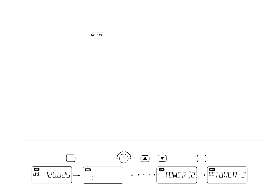
■Memory names
ïProgramming memory names
qSelect the memory channel to be programmed:
➥Push [V/M] to select memory mode.
➥Turns [DIAL] to select the memory channel.
wPush [V/M] for 5 sec. to enter memory name writing mode.
•The first character of the name flashes.
eTurns the [DIAL] as many times as necessary to enter the
desired name.
•To erase a character, overwrite with a space (displayed as _).
•To move the cursor forwards or backwards, use [Y] or [Z].
•Push [SQL] for 2 sec. to erase all characters.
rPush [SCAN/MW] for 2 sec. to input the set name.
•Flashing stops.
•Memory channels can be programmed with names of up to 7
characters in length.
•When no name is programmed, the display shows the operating
frequency.
NOTE: •Push PTT switch to abort the programming memory
name.
•The following characters can be used in names:
➥0 to 9,A to Z (capitals), (space), $,%,’,(,),✽,+,“ ,
”,–,/,<,=,>,?,@,[,\,],^,_ and `.
V/M
for 5 sec.
V/M
for 1 sec.
+or
[EXAMPLE]: Setting the name to “ TOWER 2”
5
OTHER FUNCTIONS
10
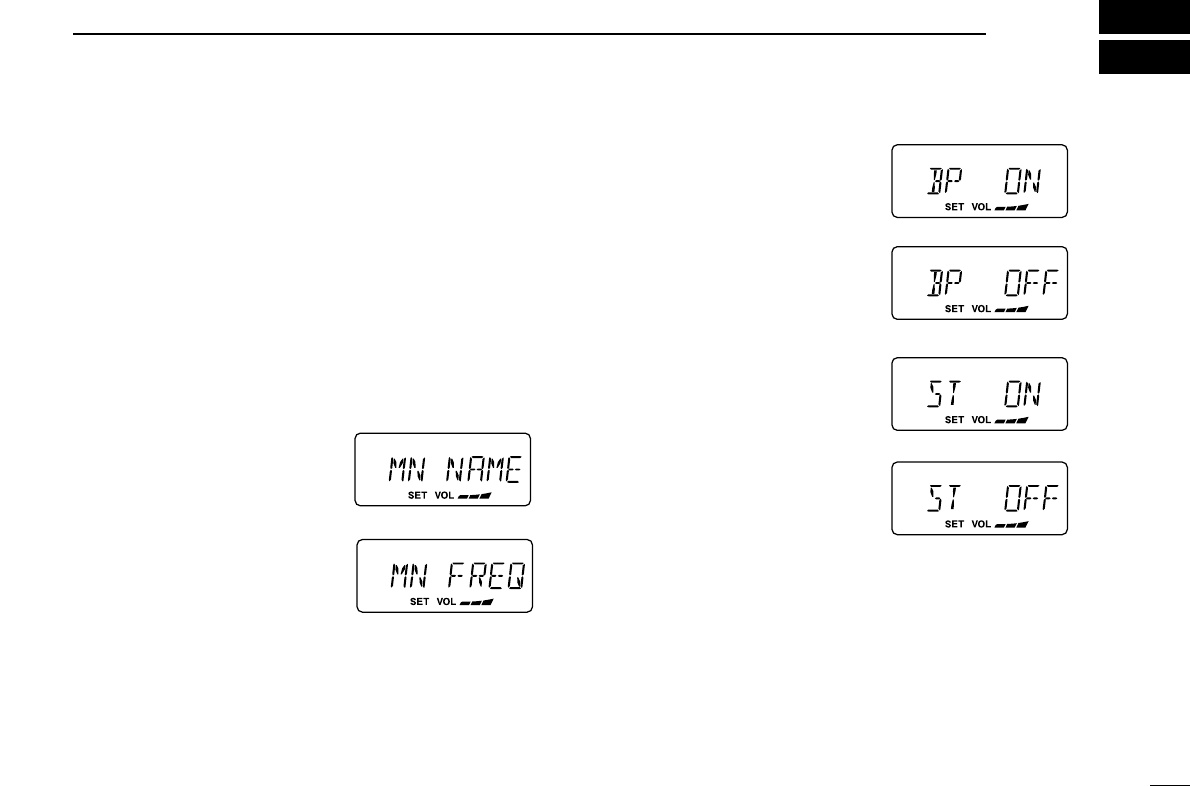
■Initial set mode
Initial set mode is accessed at power ON and allows you to
set seldom-changed settings. In this way you can “customize”
transceiver operations to suit your preferences and operating
style.
DEntering initial set mode
qWhile pushing and holding [V/M] + [TS(DIAL)], push
[POWER] sw to turn power ON.
•The transceiver enters initial set mode and “MN”, “BP”, “ST”or
“PR”(p. 11) appears on the display.
wPush [TS(DIAL)] to select the
desired item as described
below and at right.
eTurn [DIAL(TS)] to select the
desired condition.
rPush [SCAN] to exit initial set
mode and select the previous
operating mode.
DMemory names
This item allows you to display a memory name instead of fre-
quency.
•When a memory channel has not been programmed with a
name, frequency indication appears instead.
DBeep tones ON/OFF
Confirmation beep tones nor-
mally sound when you push a
key. These can be turned ON or
OFF as you prefer.
DSide tones ON/OFF
When using an optional headset
such as those from the David
Clark Co. via the adapter, the
transceiver outputs your trans-
mitted voice to the headset for
monitoring.
•Optional OPC-871 HEADSET
ADAPTER is required.

OTHER FUNCTION
5
11
DPriority channel
The priority channel is used to store your most often-used
channel for quick recall. In addition the priority channel is
monitored during priority scan modes. The default setting for
the priority channel will differ depending on pre-programming.
➥Push [PRI] to toggle the priority
channel mode or previous
mode.
•Setting the priority channel
qWhile pushing and holding
[V/M] and [DIAL(TS)], push
[POWER] to turn the power
ON.
• The transceiver enters initial set
mode.
wPush [TS(DIAL)] to select the
priority channel set mode.
eSelect the desired channel
number as a priority channel or
OFF with [DIAL].
rPush [POWER] to turn power
OFF.
NEVER select the blank memory channel as the priority
channel. In such case priority automatically sets to OFF posi-
tion.
6
CONNECTION AND INSTALLATION
12
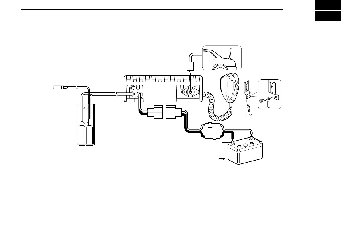
■Rear panel and connections
qConnects to an antenna.
Ask your dealer about antenna selection and best installa-
tion location.
wMICROPHONE HANGER
Connect the supplied microphone hanger to the vehicle’s
ground for hanger scan function when hanging or releasing
the microphone.
eDC POWER RECEPTACLE
Connects to a 12 or 24 V DC battery. Pay attention to po-
larities. NEVER connect to a over 27 V battery. This could
damage the transceiver.
rEXTERNAL SPEAKER JACK
Connect a 4 Ω,10 W (Max.) external speaker, if desired.
CAUTION : Be sur to use the external speaker’s power
input rating more than 10 W, other wise the speaker dam-
age may occur.
tOPTIONAL HEADSET ADAPTER (OPC-871)
Connect an optional headset. (See p. 17)
¤
⁄
‹
›
fi
black: .
red: ,
External speaker jack
OPC-871 HEADSET
ADAPTER (Option)
Antenna
Supplied DC
power cable 12 V or 24 V
Battery
13
6CONNECTION AND INSTALLATION
■Mounting
The universal mounting bracket supplied with your transceiver
allows overhead or dashboard mounting. Please read the fol-
lowing instructions carefully.
•Mount the transceiver securely with the 4 supplied screws
(M5 ×20) to a surface which is more than 10 mm thick and
can support more than 5 kg.
•Mount the transceiver so that the face of the transceiver is
at 90 ˚ to your line of sight when operating.
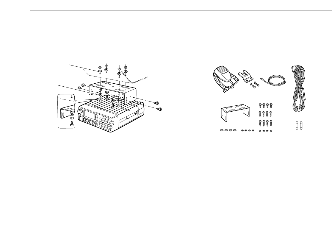
■Supplied accessories
qMicrophone . . . . . . . . . . . . . . . . . . . . . . . . . . . . . . . . . . . . . . . .1.
wMicrophone hanger and screw set . . . . . . . . . . . . . . . . . . . .1 set
eMicrophone cable . . . . . . . . . . . . . . . . . . . . . . . . . . . . . . . . . . . .1
rDC power cable (OPC-344) . . . . . . . . . . . . . . . . . . . . . . . . . . . .1
tMounting bracket . . . . . . . . . . . . . . . . . . . . . . . . . . . . . . . . . . . .1
yBracket bolts . . . . . . . . . . . . . . . . . . . . . . . . . . . . . . . . . . . . . . . .4
uMounting screws (M5 × 12) . . . . . . . . . . . . . . . . . . . . . . . . . . . . .4
iSelf-tapping screws (M5 ×20) . . . . . . . . . . . . . . . . . . . . . . . . . .4
oFlat washers . . . . . . . . . . . . . . . . . . . . . . . . . . . . . . . . . . . . . . . .4
!0 Spring washers . . . . . . . . . . . . . . . . . . . . . . . . . . . . . . . . . . . . . .4
!1 Nuts . . . . . . . . . . . . . . . . . . . . . . . . . . . . . . . . . . . . . . . . . . .4
!2 Fuses (10 A) . . . . . . . . . . . . . . . . . . . . . . . . . . . . . . . . . . . . . . . .2
12
3
4
5
6
7
8
90AB
Flat washer
Spring washer
When using
self-tapping screws

14
7
CLONING
DData cloning
Cloning allows you to quickly and easily
transfer the programmed contents from one transceiver to
another transceiver, or, data from PC to a transceiver using
the optional CS-A110 cloning software.
DTransceiver to transceiver cloning
qConnect the OPC-591 CLONING CABLE with adapter plugs to
the [MIC] jack of the master and slave transceivers.
•The master transceiver is used to send data to the slave trans-
ceiver.
wWhile pushing and holding [Y] + [Z] + [V/M], push
[POWER] ON to enter cloning mode (master transceiver
only—power ON only for slave transceiver).
•“CLONE”appears and the
transceivers enter the clone
standby condition.
ePush [POWER] on the mas-
ter transceiver.
•“CL-OUT”appears in the
master transceiver’s display.
•“CL-IN”appears automati-
cally in the slave trans-
ceiver’s display.
eWhen cloning is finished, turn
power OFF, then ON again to
exit cloning mode.
DCloning using PC
Data can be cloned to and from a PC (IBM compatible) using
the optional CS-A110 CLONING SOFTWARE and the optional OPC-
478 CLONING CABLE+ OPC-592 CLONING CABLE ADAPTER. Consult the
CS-A110 CLONING SOFTWARE HELP message for details.
DCloning error
When the display at right ap-
pears, a cloning error has oc-
curred.
In this case, both transceivers automatically return to the
clone standby condition and cloning must be repeated.
]

15
SPECIFICATIONS
8
DGeneral
•Frequency coverage : 118 to 136.975 MHz
•Channel spacing : 25 kHz or 25/8.33 kHz
•Mode : AM (6K00A3E)
•Number of memory channels : 20
•Acceptable power supply : 13.75 V or 27.5 V DC
(negative ground)
•Usable temp. range : –30˚C to +60˚C
•Frequency stability : ±5 ppm
•Current drain (at 13.75 V DC):
Tx 5 A (at max. power)
Rx 4 A ( at AF max.)
0.5 A (at STAND BY)
•Antenna impedance : 50 Ω(nominal)
•Dimensions : 150(W)✕50 (H)✕180 (D) mm
(projections not incl.) 529/32(W)✕131/32(H)✕73/32(D) in
•Weight : 1.5 Kg; 3 lb 5 oz
DTransmitter
•Output power : 36 W (pep)
9 W (carrier) typical
•Modulation : Last Stage modulation
•Modulation limiting : 70 to 100 %
•Audio harmonic distortion : Less than 10 %
(at 85 % modulation)
•Hum and noise ratio : More than 40 dB
•Spurious emissions : –16dBm or less
DReceiver
•Receive system : Double conversion
superheterodyne
•Intermediate frequencies : 1st 38.85 MHz
2nd 450 kHz
•Sensitivity (at 6dB S/N) : Less than 1 µV (pd)
•Squelch sensitivity : Less than 0.3 µV (pd)
(at threshold)
•Selectivity
25 kHz ch. spacing : More than ±8 kHz (at –6 dB)
Less than ±17 kHz (at –40 dB)
Less than ±25 kHz (at –60 dB)
8.33 k Hz ch. spacing More than ±2.778 kHz (at –6 dB)
Less than ±7.37 kHz (at –60 dB)
•Spurious response rejc, : More than 74 dBµ
•Audio output power : More than 10 W (at 13.75 V DC
with 8 Ωload 60 % MOD. 10%
distortion)
Side tone More than 100 mW (with 500 Ω
load 60% MOD. 10 % distortion)
•Noise and hum : More than 25 dB
•Audio output imoedance : 8 Ωor with 500 Ω
All stated specifications are subject to change without
notice or obligation.

16
8
SPECIFICATIONS (VFO CHANNEL ID LIST)
Operating Freq. Channel spacing Channel ID
(MHz) (kHz) (Displaied Freq.)
118.0000 25 118.000
118.0250 25 118.025
118.0500 25 118.050
118.0750 25 118.075
118.1000 25 118.100
etc
Operating Freq. Channel spacing Channel ID
(MHz) (kHz) (Displaied Freq.)
118.0000 25 118.000
118.0000 8.33 118.005
118.0083 8.33 118.010
118.0167 8.33 118.015
118.0250 25 118.020
118.0250 8.33 118.030
118.0333 8.33 118.035
118.0417 8.33 118.040
118.0500 25 118.050
118.0500 8.33 118.055
118.0583 8.33 118.060
118.0667 8.33 118.065
118.0750 25 118.070
118.0750 8.33 118.080
118.0833 8.33 118.085
118.0917 8.33 118.090
118.1000 25 118.100
118.1000 8.33 118.105
etc
•Channel spacing: 25 kHz (Actual frequency is displaied.)
•Channel spacing: 8.33 kHz (Europe version only)
•Channel spacing: 8.33/ 25 kHz auto selection mode
Operating Freq. Channel spacing Channel ID
(MHz) (kHz) (Displaied Freq.)
118.0000 8.33 118.005
118.0083 8.33 118.010
118.0167 8.33 118.015
118.0250 8.33 118.030
118.0333 8.33 118.035
118.0417 8.33 118.040
118.0500 8.33 118.055
118.0583 8.33 118.060
118.0667 8.33 118.065
118.0750 8.33 118.080
118.0833 8.33 118.085
118.0917 8.33 118.090
118.1000 8.33 118.105
etc

17
9OPTIONS
DOther options
OPC-871 HEADSET ADAPTER (See right.)
CS-A110
CLONING SOFTWARE
Provides quick and easy programming of items, including pri-
vate channels, scan settings, etc., via an IBM®compatible
PC (Microsoft®Windows®95/95) to transceiver.
OPC-478
CLONING CABLE
OPC-592
CLONING CABLE ADAPTOR
These three components work as one set and provide a quick
and easy programming of items, including memory channels,
memory names and set mode contents, etc. via a PC.
OPC-591
CLONING CABLE
Cloning cable for transceiver to transceiver. Very convenient
when programing cloning process. Allows transfer of pro-
grammed contents from one transceiver to another.
■OPC-871 HEADSET ADAPTER
(option)
When using an optional headset, such as those from the
David Clark Co. via the adapter, the transceiver outputs your
transmitted voice to the headset for monitoring. (pgs. 5, 10)
IBM®is a registered trademark of International Business Machines.
Microsoft and Windows are registered trademarkes of Microsoft Cor-
poration in the U.S.A. and other countries.
HEADSET
(Must be purchased
separately.)
PTT switch
Use a PTT switch with a 3.5
mm diameter plug, if re-
quired.
DConnection

18
10
OPTIONS
DThe optional OPC-871 HEADSET ADAPTER install as
follows.
qTurns the power OFF, then disconnect the DC power
cable.
wUnscrew the 4 screws, then remove the bottom cover. (Fig. 1)
eInsert the connector as shown below. (Fig. 2)
eMount the phone plug attachment together with the mo-
bile mounting bracket with 2 supplied screws. (Fig. 3)
•Use the upper side mounting hole.
•You can mount the attachment on either side of the
transceiver.
Bent the plastic
dust cover be-
fore install the
strain relief into
the notch.
Fig. 3
Fig. 1
Fig. 2

6-9-16 Kamihigashi, Hirano-ku, Osaka 547-0004 Japan
A-5616?-1EX
Printed in Japan
© 1999 Icom Inc.