IDS GeoRadar s r l ALADDIN-NA Ground Penetrating Radar User Manual ALADDIN NA
IDS Ingegneria dei Sistemi SpA Ground Penetrating Radar ALADDIN NA
UserManual.wiki
>
IDS GeoRadar s r l
>
ALADDIN NA User Manual
user manual
Navigation menu
Upload a User Manual
Namespaces
Wiki Guide
HTML
PDF
Info
Views
User Manual
Discussion / Help
Navigation

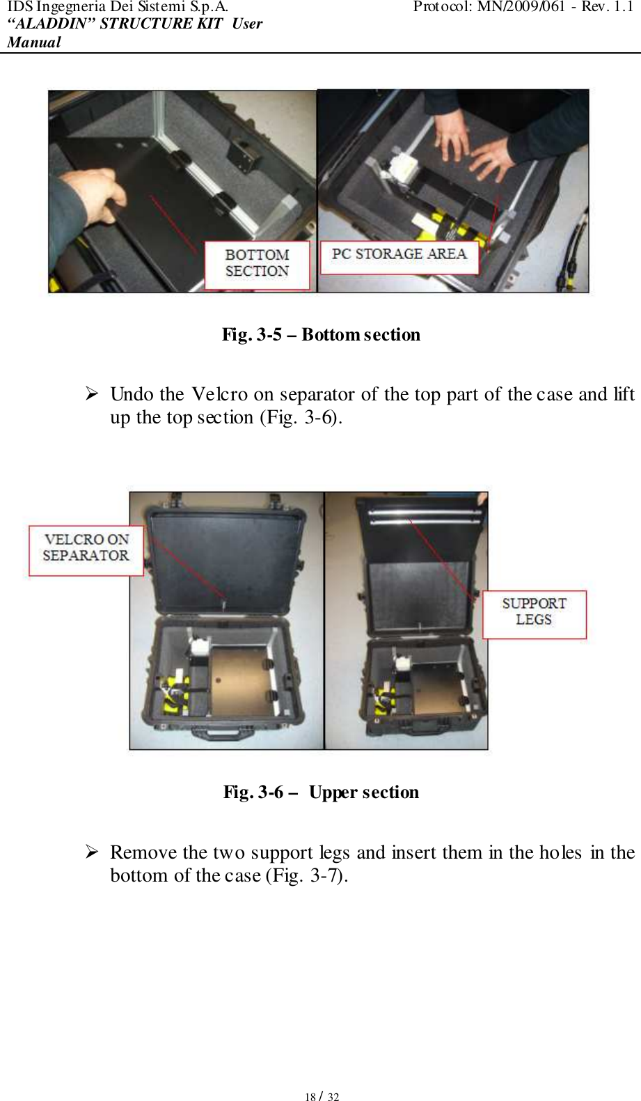
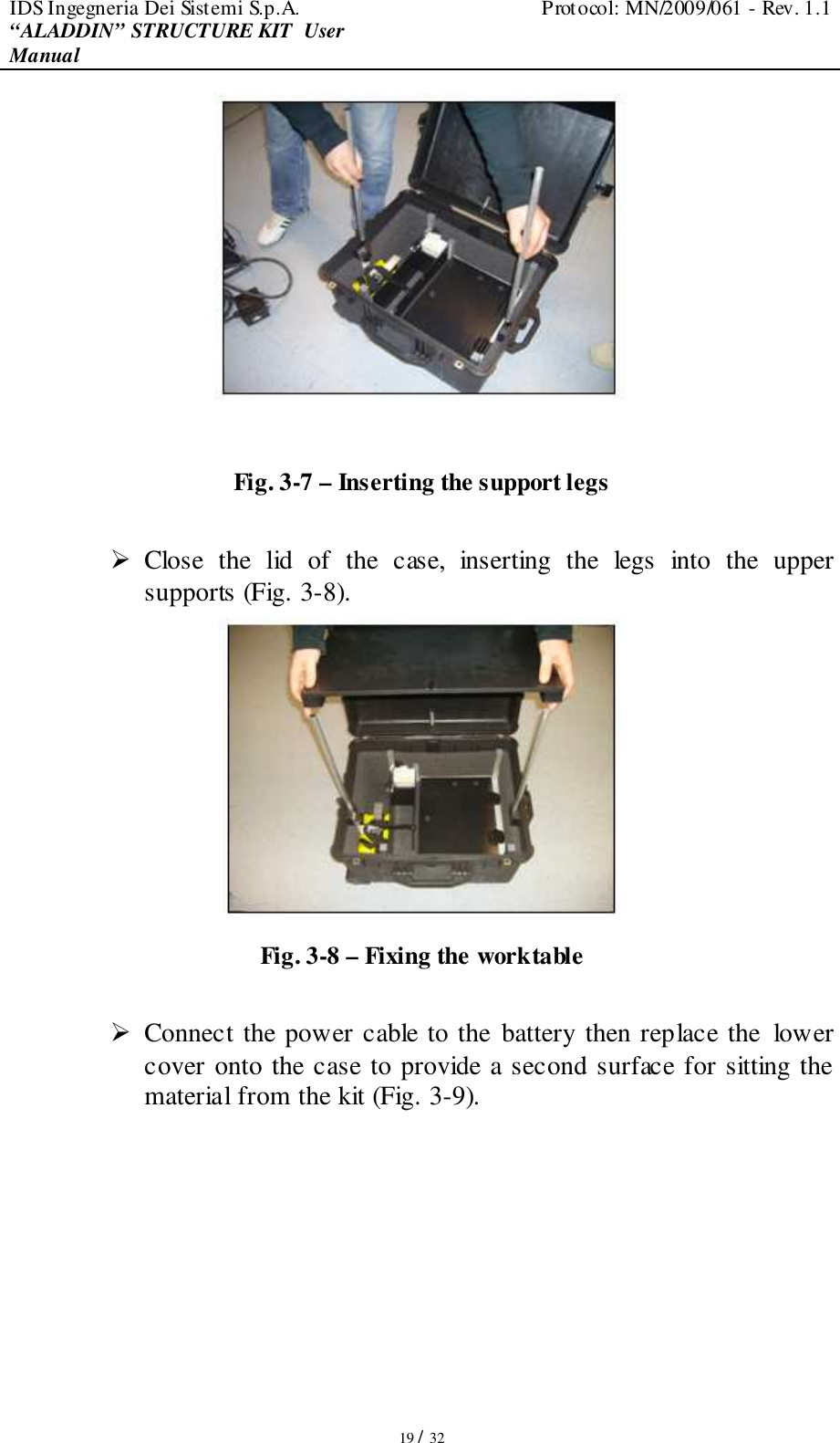
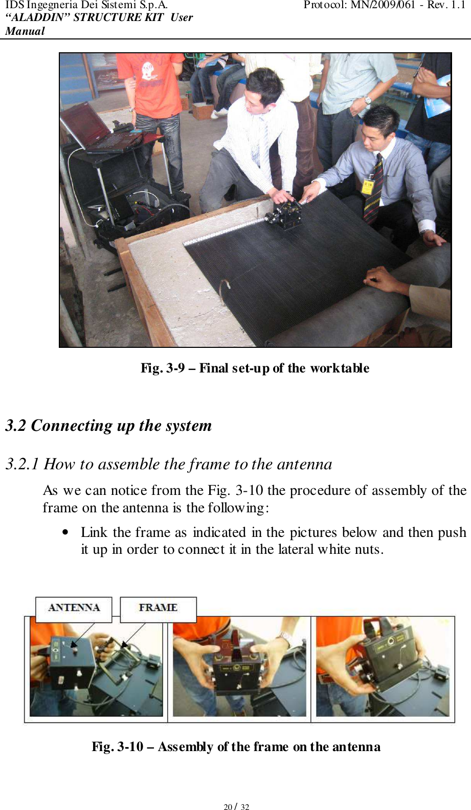
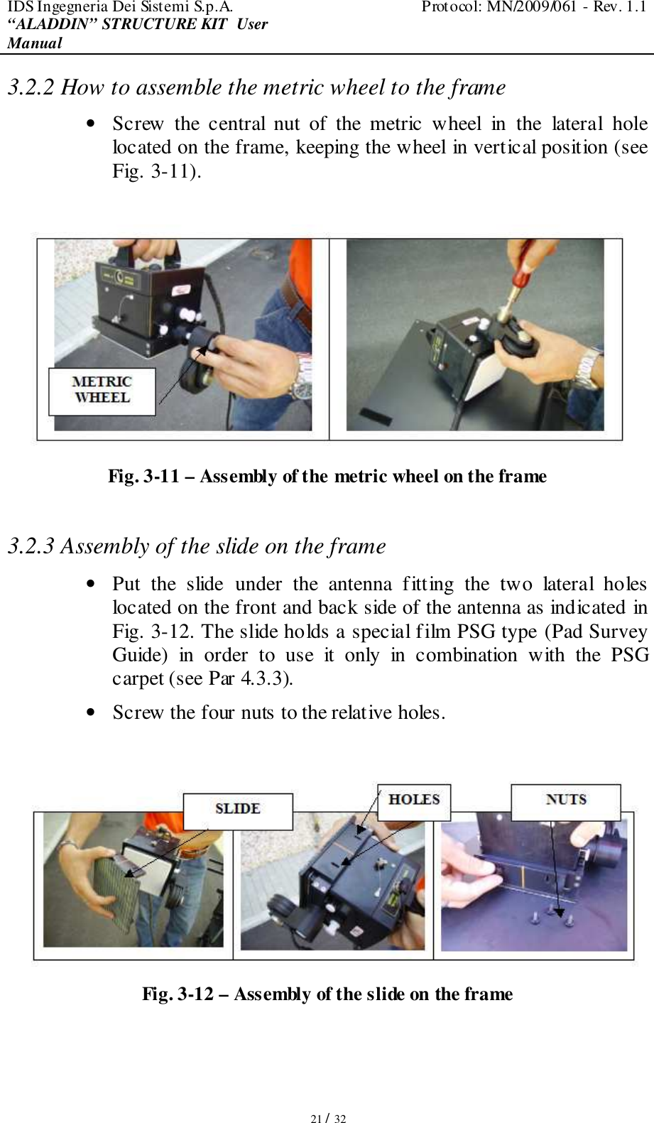
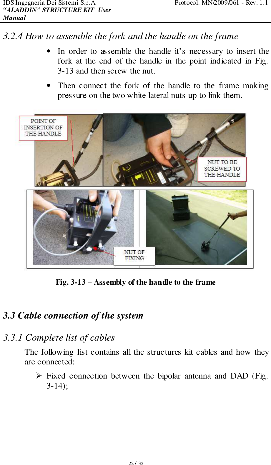
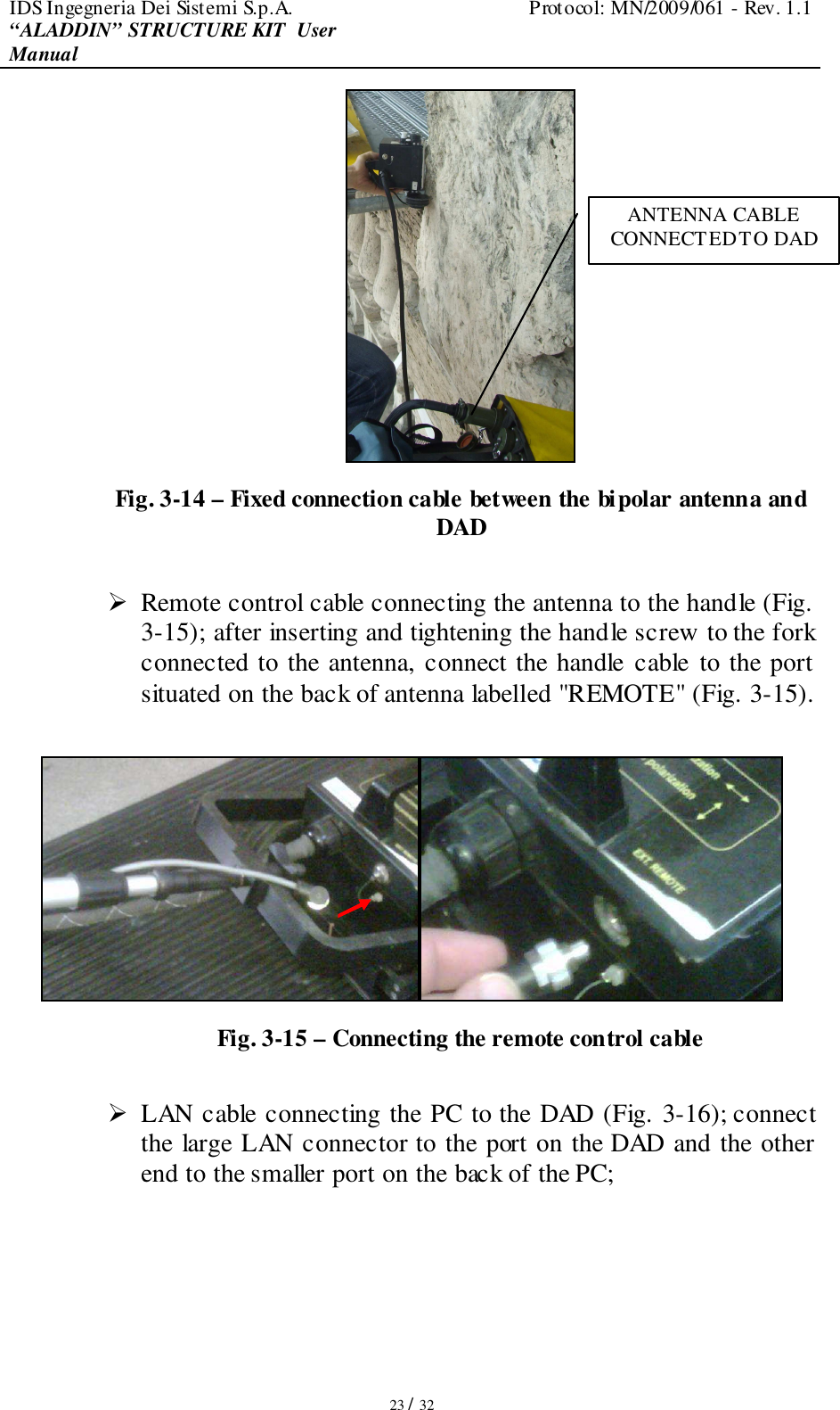
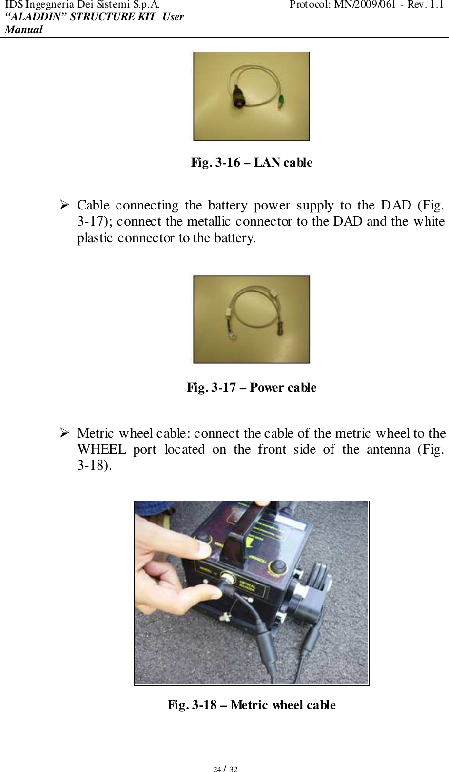
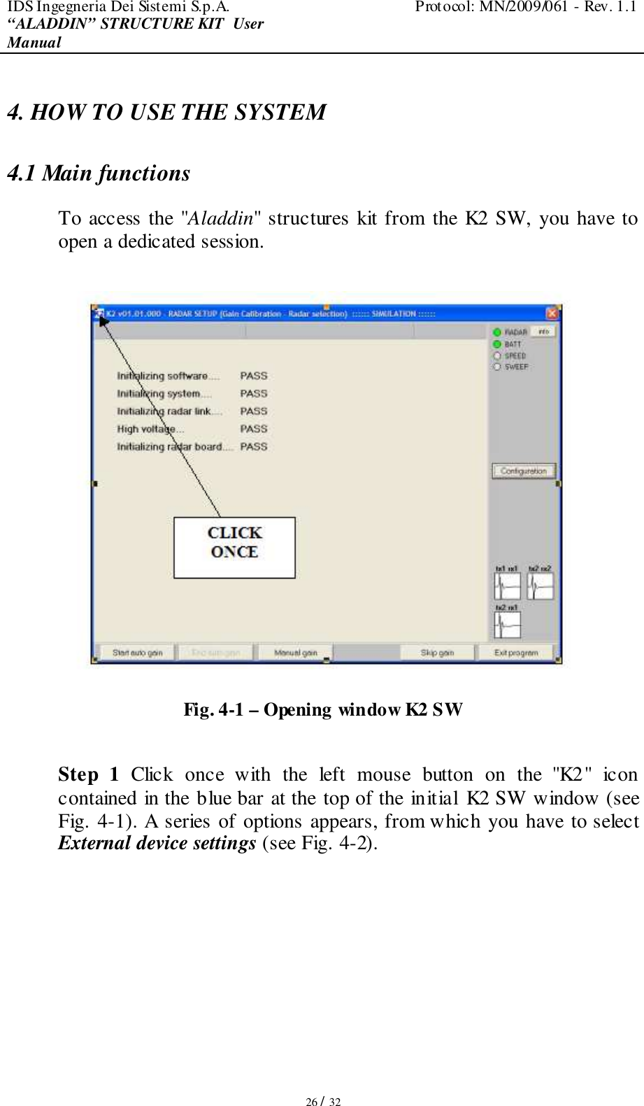
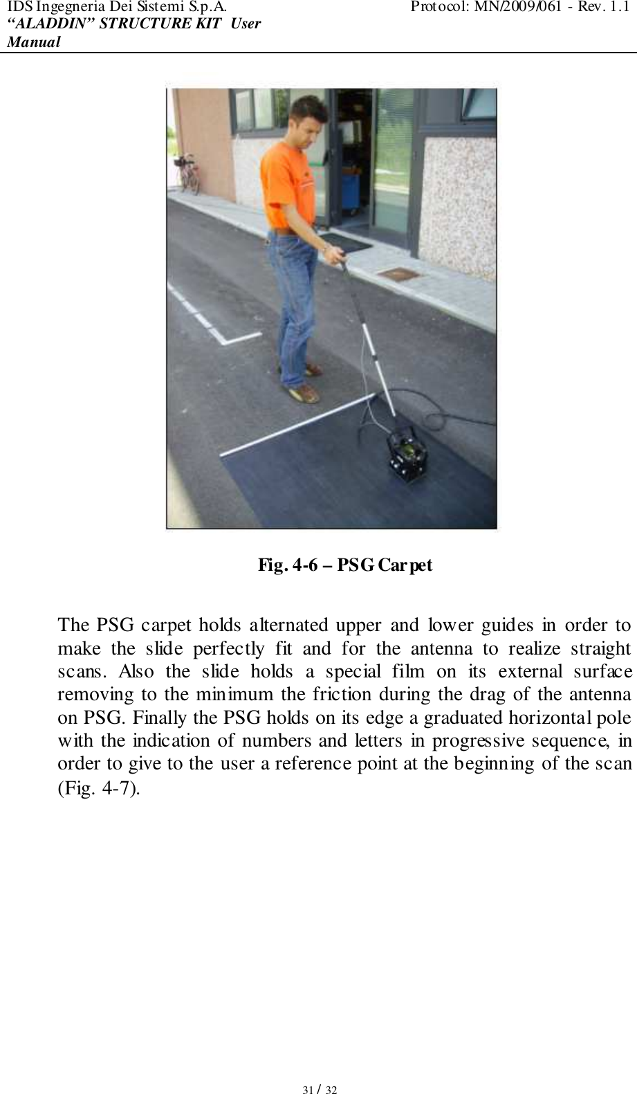
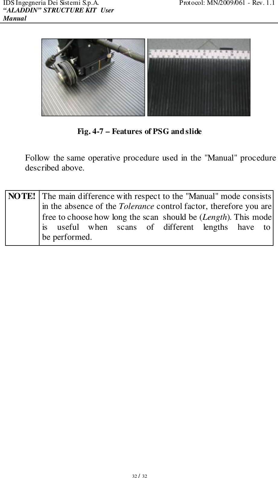
![IDS Ingegneria Dei Sistemi S.p.A. Protocol: MN/2009/061 - Rev. 1.1 “ALADDIN” STRUCTURE KIT User Manual 13 / 32 1. INTRODUCTION This manual contains a complete description of the "Aladdin" structures kit, including details on how to assemble the kit hardware, use it and operate the software interface 1.1 Purpose This document is intended to be used as a guide for the installation and use of the "Aladdin" structures kit. 1.2 Field of application This product must only be used for applications in the civil engineering field. 1.3 Reference 1.3.1 Referenced Documents [RD1] MN/2006/052 (K2 Data Acquisition Software User's guide) [RD2] MN/2005/002 (GRED 3D Data Elaboration Software). 1.4 Acronyms and Definitions 1.4.1 Acronyms K2: IDS georadar data acquisition software. DAD: radar control unit 1.4.2 Definitions Field survey: a group of field acquisitions relating to a single survey Raw data: unprocessed data obtained during a field survey. Maps: graphics showing the change in received radar signal (signal intensity in gray scale) with respect to the scanning direction. These signals must be processed to be comprehensible](https://usermanual.wiki/IDS-GeoRadar-s-r-l/ALADDIN-NA/User-Guide-1289960-Page-13.png)