IDS GeoRadar s r l ALADDIN-NA Ground Penetrating Radar User Manual ALADDIN NA
IDS Ingegneria dei Sistemi SpA Ground Penetrating Radar ALADDIN NA
user manual
Tot pag. N°. = 32
- PRO/010/M1 Rev 3 -
INGEGNERIA DEI SISTEMI S.p.A.
Rev. 1.1
Protocol: MN/2009/061
“ALADDIN” STRUCTURE KIT
USER MANUAL
Pisa, 12/02/2010
“ALADDIN”
STRUCTURE KIT
User Manual

IDS Ingegneria Dei Sistemi S.p.A. Protocol: MN/2009/061 - Rev. 1.1
“ALADDIN” STRUCTURE KIT User
Manual
2
/
32
Document Evolution
Revision Date Reason of change
Rev. 1.0 31/08/2009 First Edition
Rev 1.1 12/02/2010 FCC Information updated
Versions covered by this document
K2 All version, K2FastWave 02.00.008.
OUR CONTACTS
IDS Ingegneria dei Sistemi S.p.A. – GeoRadar Division
Via Sterpulino, 20
56121 Ospedaletto (PISA) - ITALIA
Tel: +39.050.967111
Fax: +39.050.967121
inforis@ids-spa.it
Customer Care department:
customercare.gpr@ids-spa.it
Tel.: +39.050.967122
Sales & Marketing department:
sales.gpr@ids-spa.it
Tel.: +39.050.967123/24/43

IDS Ingegneria Dei Sistemi S.p.A. Protocol: MN/2009/061 - Rev. 1.1
“ALADDIN” STRUCTURE KIT User
Manual
3
/
32
DISCLAIMER
IDS WILL NOT BE HELD RESPONSIBLE FOR THE
CONSEQUENCES OF AN
IMPROPER USE OF THE EQUIPMENT AND/OR THE SOFTWARE.
THIS SOFTWARE MAY INCLUDE AUTOMATED DATA
PROCESSING AND
ANALYSIS TOOLS.
WHILE EVERY EFFORT IS MADE TO ENSURE THE
ACCURACY OF THE
INFORMATION PROVIDED BY THOSE TOOLS, THE
Y MUST NOT BE
INTENDED AS A SUBSTITUTE FOR INTELLIGENT ANAL
YSIS; RATHER, THEY
HAVE TO BE INTENDED AS AN ADVISOR AND TH
E USER MUST NOT
COMPLETELY RELY ON THE RESULTS PROVIDED
BY THEM TO GIVE THE
COMPLETE ANSWER.
IDS INGEGNERIA DEI SISTEMI SPA ASSUMES NO LIABILITY FOR ANY
DIRECT, INDIRECT, SPECIAL, INCIDENTAL OR CON
SEQUENTIAL DAMAGES
OR INJURIES CAUSED BY SUCH RELIANCE ON THE ACCURACY,
RELIABILITY, OR TIMELESS OF THE INFORMATION PROVIDED BY THOSE
TOOLS.
ANY PERSON OR ENTITY WHO RELIES ON INFORMATION OBTAINED FROM
THE AUTOMATED DATA PROCESSING/ANALYSIS TOOLS ONLY, DOE
S SO AT
HIS OR HER OWN RISK
IDS Ingegneria Dei Sistemi S.p.A. Protocol: MN/2009/061 - Rev. 1.1
“ALADDIN” STRUCTURE KIT User
Manual
4
/
32
SAFETY INFORMATION
The equipment conforms to the following requirements set by EC
regulations, including subsequent modifications, and to the legislation set
by the member states that implement these regulations:
1999/05/EEC Radio Directive
Warning: this equipment is destined for use in industrial environments
(Class A apparatus). In residential, commercial and light industry
environments, this apparatus may generate radio interference: in this case,
the user may be requi
red to operate while taking appropriate
countermeasures.
The apparatus is sensitive to the presence of external electromagnetic fields,
which may reduce its performance.
IDS Ingegneria Dei Sistemi S.p.A. Protocol: MN/2009/061 - Rev. 1.1
“ALADDIN” STRUCTURE KIT User
Manual
5
/
32
SAFETY INFORMATION
The equipment conforms to the following requirements set
by EC
regulations, including subsequent modifications, and to the legislation set
by the member states that implement these regulations:
1999/05/EEC Radio Directive
Warning: this equipment is destined for use in industrial environments
(Class A apparatus
). In residential, commercial and light industry
environments, this apparatus may generate radio interference: in this case,
the user may be required to operate while taking appropriate
countermeasures.
The apparatus is sensitive to the presence of externa
l electromagnetic fields,
which may reduce its performance.
IDS Ingegneria Dei Sistemi S.p.A. Protocol: MN/2009/061 - Rev. 1.1
“ALADDIN” STRUCTURE KIT User
Manual
6
/
32
!
WARNING
CLEANING INFORMATION
Before cleaning any external parts of the apparatus, make sure
that all cables have been disconnected, including the powe
r
supply cable. If a damp cloth is used, make sure it is not too wet,
to avoid any damage to the electrical components of the
equipment. Wait until the equipment is totally dry before
reconnecting the cables.
The system should be cleaned periodically using a damp cloth.
Do not use solvents or abrasive detergents.
Do not apply liquid directly to the electrical contacts of the
various connectors. If a specific spray is used to clean the PC
TFT monitor, make sure it is not flammable; ion any case, do not
spray
it directly on the screen, instead, spray it onto the cleaning
cloth.

IDS Ingegneria Dei Sistemi S.p.A. Protocol: MN/2009/061 - Rev. 1.1
“ALADDIN” STRUCTURE KIT User
Manual
7
/
32
BATTERIES REMOVAL INFORMATION
Laptop Batteries:
Manufacturer: PANASONIC
Type: Li-ion Ni
Characteristics: 10.65V 5.7Ah
Removal instructions:
1. turn off the laptop;
2. open the drawer with the symbol of the batteries;
3. extract the battery pack pulling the tab.
Radar batteries:
Manufacturer: FIAMM FG21202 / SAFT MP176065
Type: rechargeable lead acid / rechargeable lithium-ion
Characteristics: 12V & 12Ah / 15V & 6.8Ah
Removal instructions:
1. disconnect the battery from the instrument:
a. pull the connector wings;
b. separate the connectors;
2. remove the battery from the cover (optional) opening the
strap.

IDS Ingegneria Dei Sistemi S.p.A. Protocol: MN/2009/061 - Rev. 1.1
“ALADDIN” STRUCTURE KIT User
Manual
8
/
32
RECICLYING
The crossed out wheeled bin symbol shown on the equipment indicates that
the product must be recycled separately from other waste at the end of its
useful life.
Separate waste disposal of this product at the end of its useful life will be
organised and managed by IDS. When you decide to dispose of the
equipment, contact IDS and follow the system that IDS has set up to permit
the separate collection of the apparatus at its life end.
Adequate separate collection for its subsequent recycling, treatment and
environmental friendly disposal contribute towards avoiding any
unnecessary effects on the environment and to health and favour the reuse or
recycling of the materials that make up the equipment. Unauthorised disposal
of this product as unsorted waste by its possessor will lead to an
administrative penalty foreseen by national regulations.

IDS Ingegneria Dei Sistemi S.p.A. Protocol: MN/2009/061 - Rev. 1.1
“ALADDIN” STRUCTURE KIT User
Manual
9
/
32
WARRANTY CERTIFICATE CONDITIONS
1) IDS Ingegneria dei Sistemi S.p.A, hereinafter referred to as IDS, warrants hardware/software
products for a period of 12 months from the delivery date to the original customer;
2) The delivery date is certified by the “ Warranty Registration Form”;
3) IDS’s hardware products will be free from defects in materials workmanship under normal use
and service;
4) IDS’s obligation is limited to repairing or replacing parts or equipment which are returned to IDS,
without alteration or further damage, and which in IDS s judgment, were defective or became
defective during normal use;
5) IDS’ software will have to be installed on a PC according to the requirement of the IDS hardware
( see IDS User’s Guide the Software Data Acquisition);
6) IDS’ s software products designed by IDS for use for IDS hardware products are warranted not to
fail to execute their programming instructions due to defects during the warranty period, provided
they are properly installed on IDS hardware products. IDS does not warrant if the IDS software
will be used and operated in hardware and software combinations not selected by IDS;
7) IDS does not assumes any liability for any direct, indirect, special, incidental or consequential
damages or injuries caused by proper or improper operation of its equipment whether defective or
not defective;
8) This software may include automated data processing and analysis tools. While every effort is
made to ensure the accuracy of the information provided by those tools, they must not be intended
as a substitute for intelligent analysis; rather, they have to be intended as an advisor and the user
must not completely rely on the results provided by them to give the complete answer. IDS
assumes no liability for any direct, indirect special, incidental or consequential damages or
injuries caused by such reliance on the accuracy, reliability, or timeliness of the information
provided by those tools. Any person or entity who relies on information obtained from the
automated data processing/analysis tools only, does so at his or her own risk;
9) IDS’s warranty does not extend and shall not apply to:
a) Products which have been repaired or altered by other than IDS personnel;
b) Products which have been subjected to misuse, neglect, accident or improper installation;
c) Products in which have been installed Hardware/Software accessories not supplied by
IDS and/or without any approval by IDS;
d) Products which have been connected to equipment different from the ones supplied by
IDS (except the PC data Logger which must conform to IDS specifications;
e) Products which have been damaged by natural disaster or calamities.
10) Before returning any equipment to IDS , you have to contact the IDS Customer Care Office that
will authorize you to return the material to be repaired;
11) Once the parts/equipment to be repaired arrive to IDS, IDS may inspect the defective products to
verify they are eligible for repair or replacement. All packing must be saved for inspection
purpose in order to assist IDS to understand the cause of the defects. IDS, will not be obliged to
repair, or replace for products returned as defective but damaged from abuse, misuse, neglicence ,
accident loss or damage in transit;
12) The final clients, is responsible for ensuring the defective products returned to be properly
packaged;
13) The above warranty are sole and exclusive, and no other warranty, whether written or oral, is
expressed or implied.

IDS Ingegneria Dei Sistemi S.p.A. Protocol: MN/2009/061 - Rev. 1.1
“ALADDIN” STRUCTURE KIT User
Manual
10
/
32
IMPORTANT NOTE FOR THE US CUSTOMERS
FCC ID: UFW-ALADDIN-NA
This device complies with part 15 of the FCC Rules:
Operation is subject to the following conditions:
1. This device may not cause harmful interference, and
2. This device must accept any interference received, Including interference that may cause undesired operation
Warning: Changes or modifications to this unit not expressly approved by the party responsible for compliance
could void the user’s authority to operate the equipment.
Operation of this device is restricted to law enforcement, fire and rescue officials, scientific research institutes,
commercial mining companies, and construction companies. Operation by any other party is a violation of 47 U.S.C.
§ 301 and could subject the operator to serious legal penalties.
Coordination Requirements.
(a) UWB imaging systems require coordination through the FCC before the equipment may be used. The operator
shall comply with any constraints on equipment usage resulting from this coordination.
(b) The users of UWB imaging devices shall supply detailed operational areas to the FCC Office o f Engineering and
Technology who shall coordinate this information with the Federal Government through the National
Telecommunications and Information Administration. The information provided by the UWB operator shall include
the name, address and other pertinent contact information of the user, the desired geographical area of operation, and
the FCC ID number and other nomenclature of the UWB device. This material shall be submitted to the following
address:
Frequency Coordination Branch., OET
Federal Communications Commission
445 12th Street, SW
Washington, D.C. 20554
ATTN: UWB Coordination
(d) Users of authorized, coordinated UWB systems may transfer them to other qualified users and to different
locations upon coordination of change of ownership or location to the FCC and coordination with existing
authorized operations.
(e) The NTIA/FCC coordination report shall include any needed constraints that apply to day-to-day operations.
Such constraints could specify prohibited areas of operations or areas located near authorized radio stations for
which additional coordination is required before operation of the UWB equipment. If additional local coordination is
required, a local coordination contact will be provided.
(f) The coordination of routine UWB operations shall not take longer than 15 business days from the receipt of the
coordination request by NTIA. Special temporary operations may be handled with an expedited turn-around time
when circumstances warrant. The operation of UWB systems in emergency situations involving the safety of life or
property may occur without coordination provided a notification procedure, similar to that contained in CFR47
Section 2.405(a)-(e), is followed by the UWB equipment user.
Notice: Use of this device as a wall imaging system is prohibited by FCC regulations.
According to the FCC Part 15 rules, the system includ es a manually operated switch
(“dead-man switch”) that causes the transmitter to cease operation within 10 seconds of
being released by the operator.
The use of this switch is further explained in this manual; specific instructions for
op erating a system sold in the US are identified by the following label

IDS Ingegneria Dei Sistemi S.p.A. Protocol: MN/2009/061 - Rev. 1.1
“ALADDIN” STRUCTURE KIT User
Manual
11
/
32
INDEX
1. INTRODUCTION .....................................................................................................13
1.1 Purpose...............................................................................................................13
1.2 Field of application.............................................................................................13
1.3 Reference ............................................................................................................13
1.3.1 Referenced Documents ..........................................................................13
1.4 Acronyms and Definitions...................................................................................13
1.4.1 Acronyms...............................................................................................13
1.4.2 Definitions..............................................................................................13
1.5 How to use this manual.......................................................................................14
2. SYSTEM COMPONENTS .......................................................................................15
3. HOW TO SET UP THE SYSTEM...........................................................................16
3.1 Opening the case.................................................................................................16
3.2 Connecting up the system ...................................................................................20
3.2.1 How to assemble the frame to the antenna ............................................20
3.2.2 How to assemble the metric wheel to the frame ....................................21
3.2.3 Assembly of the slide on the frame........................................................21
3.2.4 How to assemble the fork and the handle on the frame .........................22
3.3 Cable connection of the system...........................................................................22
3.3.1 Complete list of cables...........................................................................22
3.4 Technical advice .................................................................................................25
4. HOW TO USE THE SYSTEM.................................................................................26
4.1 Main functions ....................................................................................................26
4.2 Functioning principles using the PSG carpet.....................................................27
4.3 Work procedure using the Aladdin system .........................................................28
4.3.1 "Automatic" mode..................................................................................28
4.3.2 “M anual” M ode......................................................................................30
4.3.3 “M anual (no check)” M ode....................................................................30

IDS Ingegneria Dei Sistemi S.p.A. Protocol: MN/2009/061 - Rev. 1.1
“ALADDIN” STRUCTURE KIT User
Manual
12
/
32
PICTURES INDEX
FIG. 2-1 – FINAL CONFIGURATION.................................................................................15
FIG. 3-1 – OPENING THE CASE.........................................................................................16
FIG. 3-2 – REMOVING THE BATTERY ............................................................................16
FIG. 3-3 – REMOVING THE DAD AND THE ANTENNA TROLLEY.................................17
FIG. 3-4 – REMOVING THE BIPOLAR ANTENNA............................................................17
FIG. 3-5 – BOTTOM SECTION...........................................................................................18
FIG. 3-6 – UPPER SECTION..............................................................................................18
FIG. 3-7 – INSERTING THE SUPPORT LEGS.....................................................................19
FIG. 3-8 – FIXING THE WORKTABLE...............................................................................19
FIG. 3-9 – FINAL SET-UP OF THE WORKTABLE.............................................................20
FIG. 3-10 – ASSEMBLY OF THE FRAME ON THE ANTENNA..........................................20
FIG. 3-11 – ASSEMBLY OF THE METRIC WHEEL ON THE FRAME................................21
FIG. 3-12 – ASSEMBLY OF THE SLIDE ON THE FRAME.................................................21
FIG. 3-13 – ASSEMBLY OF THE HANDLE TO THE FRAME.............................................22
FIG. 3-14 – FIXED CONNECTION CABLE BETWEEN THE BIPOLAR ANTENNA AND
DAD ...........................................................................................................................23
FIG. 3-15 – CONNECTING THE REMOTE CONTROL CABLE..........................................23
FIG. 3-16 – LAN CABLE.....................................................................................................24
FIG. 3-17 – POWER CABLE...............................................................................................24
FIG. 3-18 – METRIC WHEEL CABLE.................................................................................24
FIG. 4-1 – OPENING WINDOW K2 SW..............................................................................26
FIG. 4-2 – EXTERNAL DEVICE SETTINGS COMMAND...................................................27
FIG. 4-3 – SELECTION WINDOW FOR ALADDIN PSG MODE.........................................27
FIG. 4-4 –ALADDIN PSG FIELD ........................................................................................28
FIG. 4-5 – ALADDIN SYSTEM...........................................................................................29
FIG. 4-6 – PSG CARPET .....................................................................................................31
FIG. 4-7 – FEATURES OF PSG AND SLIDE.......................................................................32

IDS Ingegneria Dei Sistemi S.p.A. Protocol: MN/2009/061 - Rev. 1.1
“ALADDIN” STRUCTURE KIT User
Manual
13
/
32
1. INTRODUCTION
This manual contains a complete description of the "Aladdin"
structures kit, including details on how to assemble the kit hardware,
use it and operate the software interface
1.1 Purpose
This document is intended to be used as a guide for the installation and
use of the "Aladdin" structures kit.
1.2 Field of application
This product must only be used for applications in the civil
engineering field.
1.3 Reference
1.3.1 Referenced Documents
[RD1] MN/2006/052 (K2 Data Acquisition Software User's guide)
[RD2] MN/2005/002 (GRED 3D Data Elaboration Software).
1.4 Acronyms and Definitions
1.4.1 Acronyms
K2: IDS georadar data acquisition software.
DAD: radar control unit
1.4.2 Definitions
Field survey: a group of field acquisitions relating to a single survey
Raw data: unprocessed data obtained during a field survey.
Maps: graphics showing the change in received radar signal (signal
intensity in gray scale) with respect to the scanning direction. These
signals must be processed to be comprehensible

IDS Ingegneria Dei Sistemi S.p.A. Protocol: MN/2009/061 - Rev. 1.1
“ALADDIN” STRUCTURE KIT User
Manual
14
/
32
Survey: the name given to a collection of acquisitions, which together
cover all the areas of a large investigation: typically an entire town or a
large urban area.
Scan: a single movement of the antenna trolley from the beginning to
the end of a pre-established path.
Data processing: this is applied to the raw data to permit the acquired
sections to be viewed in a comprehensible way.
Setup: initialisation of a piece of equipment or a software process
1.5 How to use this manual
This manual is divided into the following sections:
Chap. 1: Introduction.
Chap. 2: System composition.
Chap. 3: How to set up the system.
Chap. 4: How to use the system.
IDS Ingegneria Dei Sistemi S.p.A. Protocol: MN/2009/061 - Rev. 1.1
“ALADDIN” STRUCTURE KIT User
Manual
15
/
32
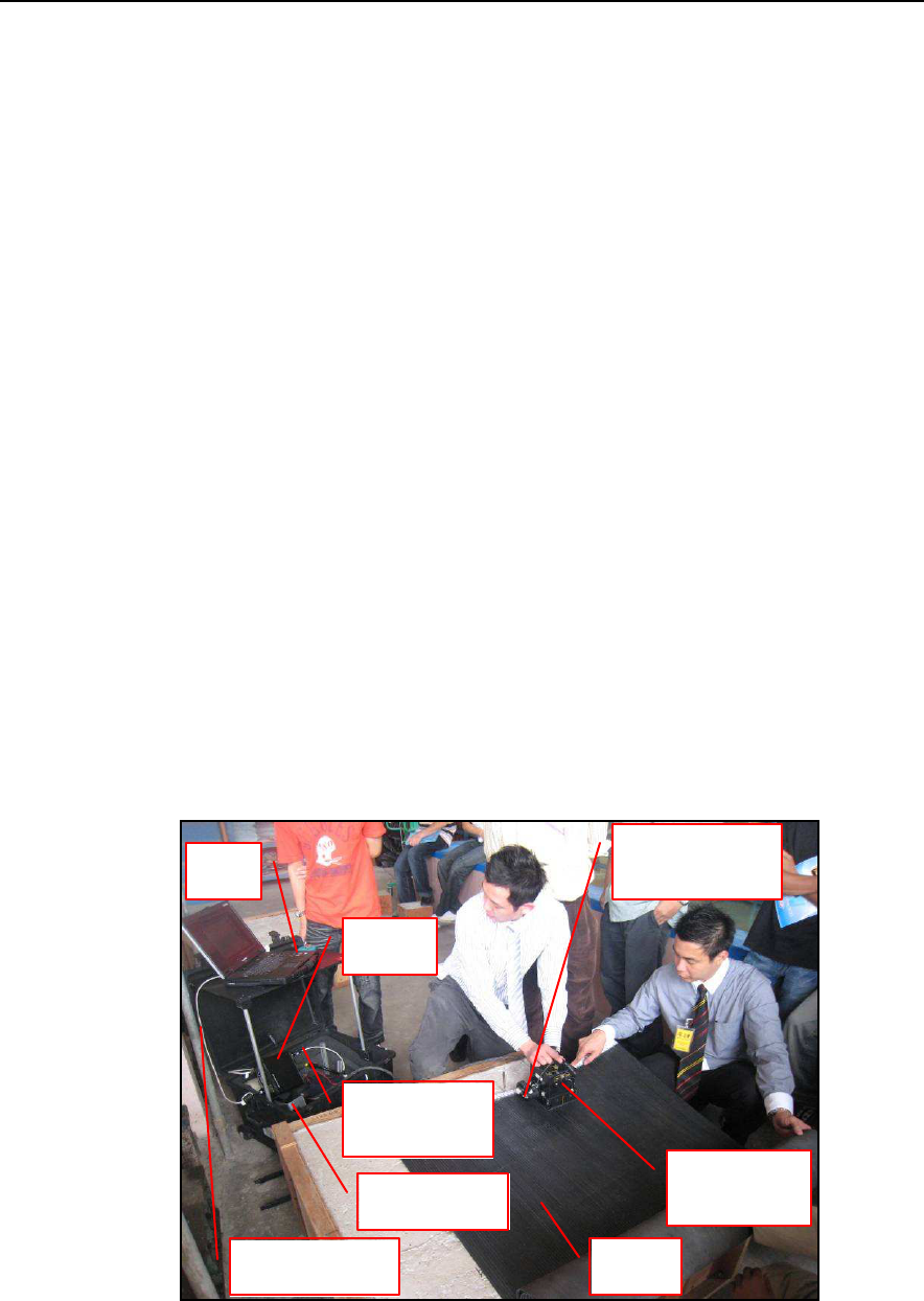
2. SYSTEM COMPONENTS
The "Aladdin" structures kit consists of the following parts:
1. Bipolar antenna
2. Connection box
3. Trolley handle.
4. Antenna survey kit
5. Notebook PC.
6. DAD box.
7. 1 cable to connect the antenna to the DAD.
8. 1 battery.
9. 1 battery charger.
10. USB stick + acquisition software.
11. CD-ROM + GRED 3D processing software.
12. Transportation case.
13. PSG (Pad Survey Guide) carpet.
Fig. 2-1 – Final configuration
LAN CABLE
PSG
PC
SURVEY
WHEEL KIT
BIPOLAR
ANTENNA
DAD
BATTERY
CABLE
BATTERY
IDS Ingegneria Dei Sistemi S.p.A. Protocol: MN/2009/061 - Rev. 1.1
“ALADDIN” STRUCTURE KIT User
Manual
16
/
32
3. HOW TO SET UP THE SYSTEM
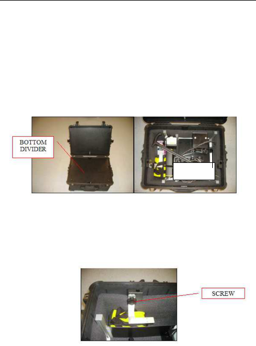
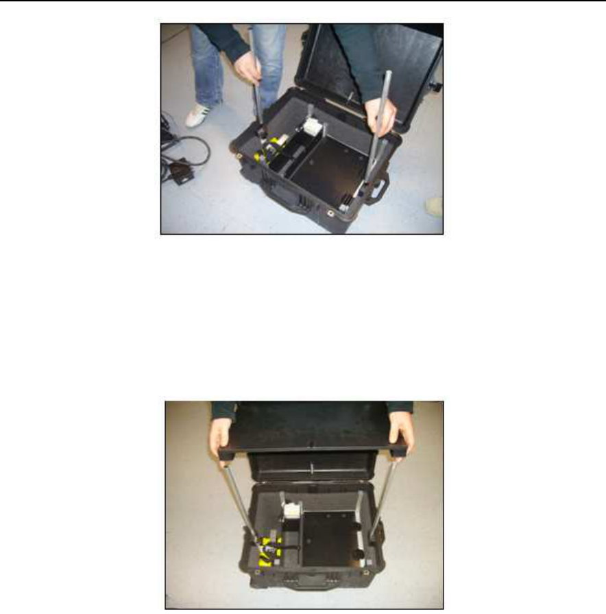
3.1 Opening the case
When you receive the case containing the "Aladdin" structures kit,
follow the procedure below:
Open the protective case, remove the bottom divider and take
out the antenna trolley steering handle (see Fig. 3-1).
Fig. 3-1 – Opening the case
If you want to remove the battery, unscrew the black screw
shown in the picture (Fig. 3-2).
Fig. 3-2 – Removing the battery
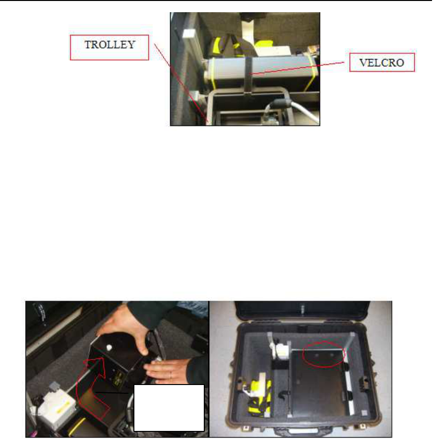
Undo the Velcro that keeps the DAD unit blocked, now remove
the DAD and the trolley (Fig. 3-3).
Equipment
IDS Ingegneria Dei Sistemi S.p.A. Protocol: MN/2009/061 - Rev. 1.1
“ALADDIN” STRUCTURE KIT User
Manual
17
/
32
Fig. 3-3 – Removing the DAD and the antenna trolley
Remove the bipolar antenna, pushing the lever towards the foam
support then lift the antenna out rotating it slightly (see the
direction of the red arrow in Fig. 3-4); when you have to replace
the antenna in the case, be careful that the white pegs on the side
of the antenna are blocked into the two holes inside the case
(indicated with the red circle).
Fig. 3-4 – Removing the bipolar antenna
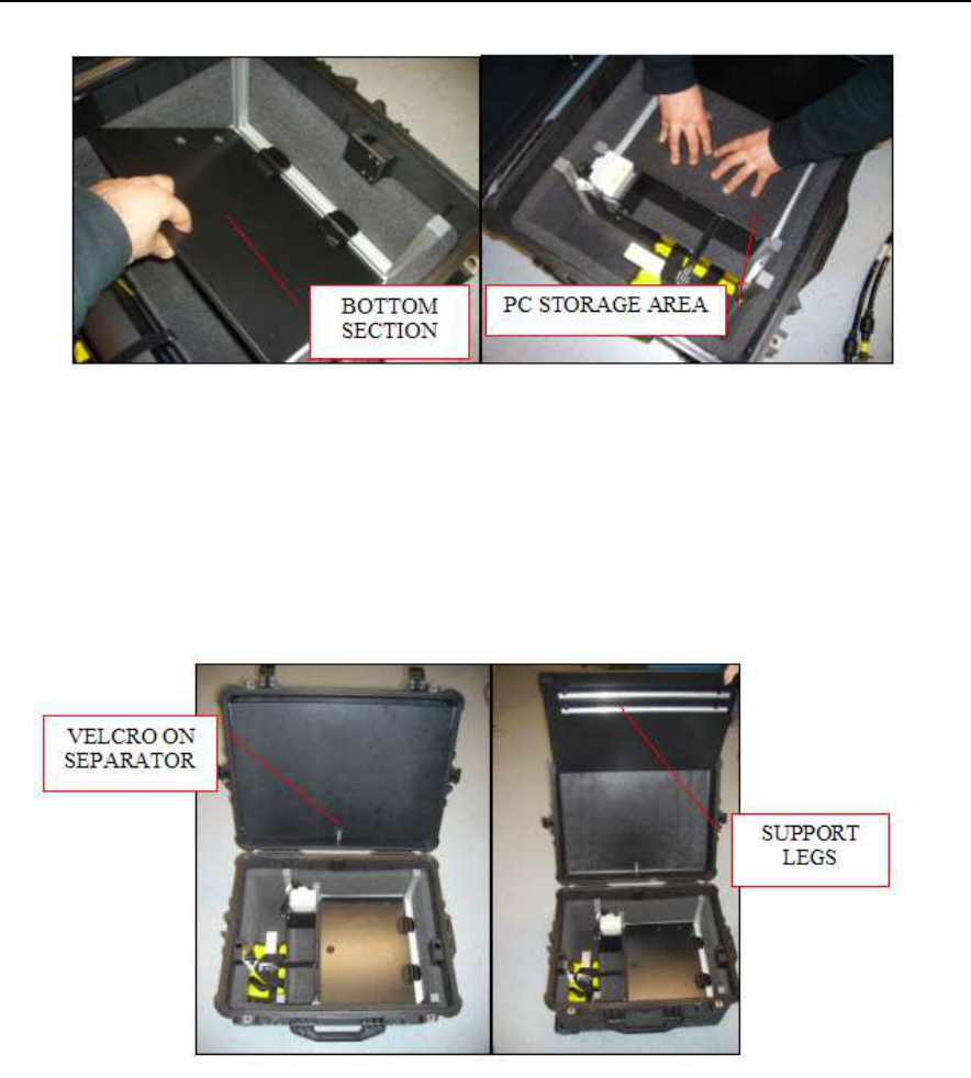
Open the bottom section (Fig. 3-4 and Fig. 3-5); this is the PC
storage area; if a PC has not been supplied with your order, you
can store your own PC here using the pre-cut foam to model a
suitably shaped space (Fig. 3-5). The maximum space available
for storing a PC is 34cm x 27cm x 5cm.
How to
remove the
antenna
IDS Ingegneria Dei Sistemi S.p.A. Protocol: MN/2009/061 - Rev. 1.1
“ALADDIN” STRUCTURE KIT User
Manual
18
/
32
Fig. 3-5 – Bottom section
Undo the Velcro on separator of the top part of the case and lift
up the top section (Fig. 3-6).
Fig. 3-6 – Upper section
Remove the two support legs and insert them in the holes in the
bottom of the case (Fig. 3-7).
IDS Ingegneria Dei Sistemi S.p.A. Protocol: MN/2009/061 - Rev. 1.1
“ALADDIN” STRUCTURE KIT User
Manual
19
/
32
Fig. 3-7 – Inserting the support legs
Close the lid of the case, inserting the legs into the upper
supports (Fig. 3-8).
Fig. 3-8 – Fixing the worktable
Connect the power cable to the battery then replace the lower
cover onto the case to provide a second surface for sitting the
material from the kit (Fig. 3-9).
IDS Ingegneria Dei Sistemi S.p.A. Protocol: MN/2009/061 - Rev. 1.1
“ALADDIN” STRUCTURE KIT User
Manual
20
/
32
Fig. 3-9 – Final set-up of the worktable
3.2 Connecting up the system
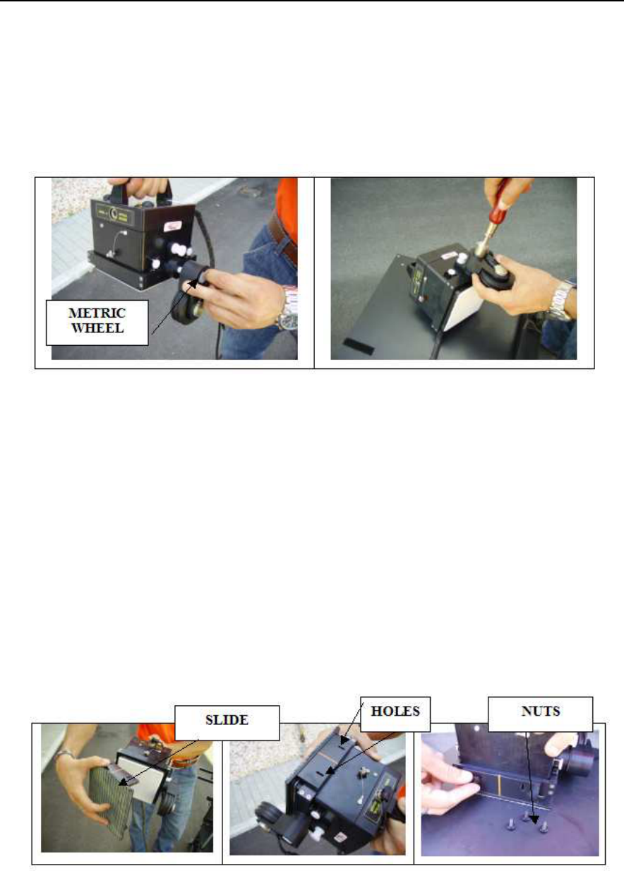
3.2.1 How to assemble the frame to the antenna
As we can notice from the Fig. 3-10 the procedure of assembly of the
frame on the antenna is the following:
• Link the frame as indicated in the pictures below and then push
it up in order to connect it in the lateral white nuts.
Fig. 3-10 – Assembly of the frame on the antenna
IDS Ingegneria Dei Sistemi S.p.A. Protocol: MN/2009/061 - Rev. 1.1
“ALADDIN” STRUCTURE KIT User
Manual
21
/
32
3.2.2 How to assemble the metric wheel to the frame
• Screw the central nut of the metric wheel in the lateral hole
located on the frame, keeping the wheel in vertical position (see
Fig. 3-11).
Fig. 3-11 – Assembly of the metric wheel on the frame
3.2.3 Assembly of the slide on the frame
• Put the slide under the antenna fitting the two lateral holes
located on the front and back side of the antenna as indicated in
Fig. 3-12. The slide holds a special film PSG type (Pad Survey
Guide) in order to use it only in combination with the PSG
carpet (see Par 4.3.3).
• Screw the four nuts to the relative holes.
Fig. 3-12 – Assembly of the slide on the frame
IDS Ingegneria Dei Sistemi S.p.A. Protocol: MN/2009/061 - Rev. 1.1
“ALADDIN” STRUCTURE KIT User
Manual
22
/
32
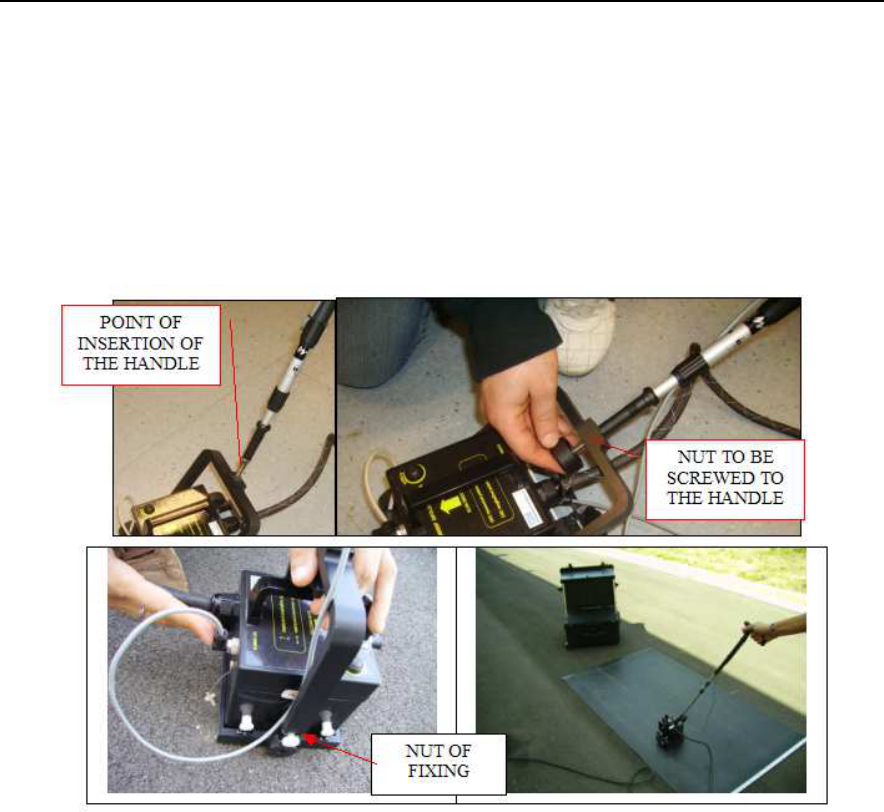
3.2.4 How to assemble the fork and the handle on the frame
• In order to assemble the handle it’s necessary to insert the
fork at the end of the handle in the point indicated in Fig.
3-13 and then screw the nut.
• Then connect the fork of the handle to the frame making
pressure on the two white lateral nuts up to link them.
Fig. 3-13 – Assembly of the handle to the frame
3.3 Cable connection of the system
3.3.1 Complete list of cables
The following list contains all the structures kit cables and how they
are connected:
Fixed connection between the bipolar antenna and DAD (Fig.
3-14);
IDS Ingegneria Dei Sistemi S.p.A. Protocol: MN/2009/061 - Rev. 1.1
“ALADDIN” STRUCTURE KIT User
Manual
23
/
32
Fig. 3-14 – Fixed connection cable between the bipolar antenna and
DAD
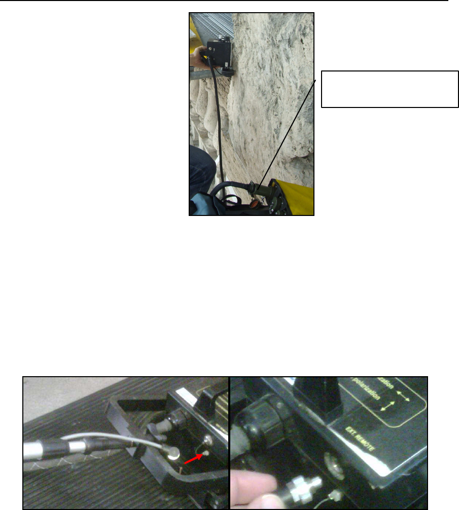
Remote control cable connecting the antenna to the handle (Fig.
3-15); after inserting and tightening the handle screw to the fork
connected to the antenna, connect the handle cable to the port
situated on the back of antenna labelled "REMOTE" (Fig. 3-15).
Fig. 3-15 – Connecting the remote control cable
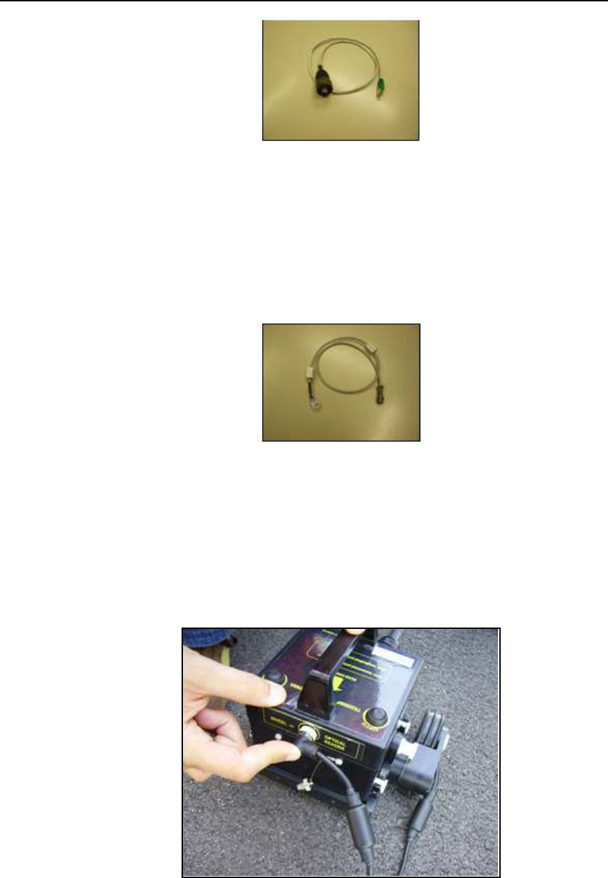
LAN cable connecting the PC to the DAD (Fig. 3-16); connect
the large LAN connector to the port on the DAD and the other
end to the smaller port on the back of the PC;
ANTENNA CABLE
CONNECTED TO DAD
IDS Ingegneria Dei Sistemi S.p.A. Protocol: MN/2009/061 - Rev. 1.1
“ALADDIN” STRUCTURE KIT User
Manual
24
/
32
Fig. 3-16 – LAN cable
Cable connecting the battery power supply to the DAD (Fig.
3-17); connect the metallic connector to the DAD and the white
plastic connector to the battery.
Fig. 3-17 – Power cable
Metric wheel cable: connect the cable of the metric wheel to the
WHEEL port located on the front side of the antenna (Fig.
3-18).
Fig. 3-18 – Metric wheel cable

IDS Ingegneria Dei Sistemi S.p.A. Protocol: MN/2009/061 - Rev. 1.1
“ALADDIN” STRUCTURE KIT User
Manual
25
/
32
3.4 Technical advice
Pay special attention to the following technical advice to avoid
operational problems:
Fix the pad to the surface being investigated with adhesive tape.
Avoid treading on the paper pad, this may damage it making it
unusable.
Block the antenna cable to the handle with Velcro when using
the device so the cable doesn't get in the way
IDS Ingegneria Dei Sistemi S.p.A. Protocol: MN/2009/061 - Rev. 1.1
“ALADDIN” STRUCTURE KIT User
Manual
26
/
32
4. HOW TO USE THE SYSTEM
4.1 Main functions
To access the "Aladdin" structures kit from the K2 SW, you have to
open a dedicated session.
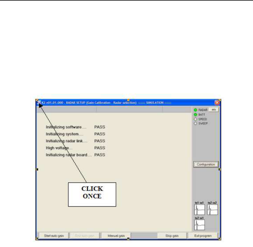
Fig. 4-1 – Opening window K2 SW
Step 1 Click once with the left mouse button on the "K2" icon
contained in the blue bar at the top of the initial K2 SW window (see
Fig. 4-1). A series of options appears, from which you have to select
External device settings (see Fig. 4-2).
IDS Ingegneria Dei Sistemi S.p.A. Protocol: MN/2009/061 - Rev. 1.1
“ALADDIN” STRUCTURE KIT User
Manual
27
/
32
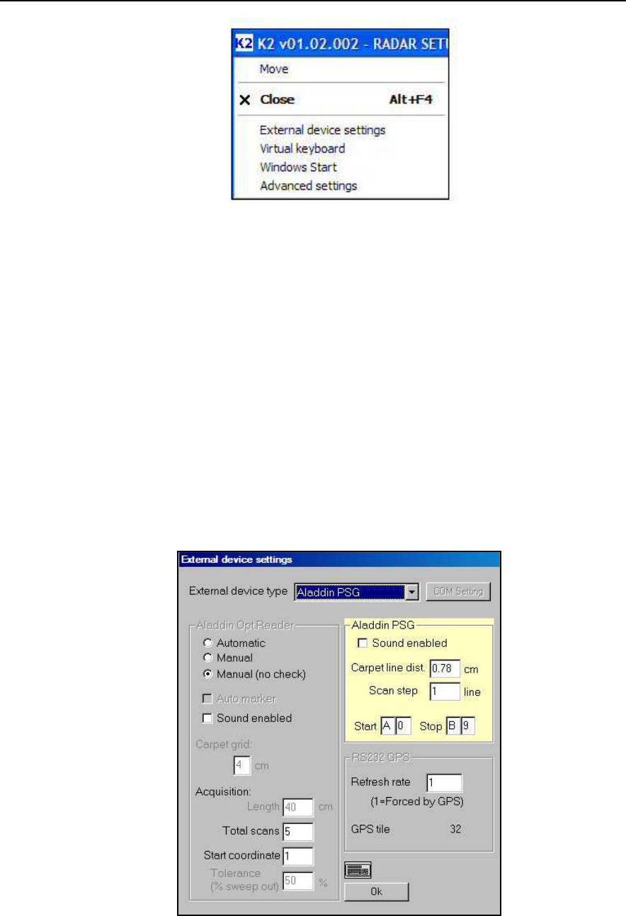
Fig. 4-2 – External device settings command
4.2 Functioning principles using the PSG carpet
Step 1 click once with the left mouse button on the “K2” icon on the
blue bar of the initial K2 SW window (see Fig. 4-1), the menu that
appears contains a series of commands, from which you should select
External device settings (see Fig. 4-2).
Step 2 this opens the window shown in Fig. 4-3, from where you can
select Aladdin PSG from the External device type field if you are
going to use the PSG carpet.
Fig. 4-3 – Selection window for Aladdin PSG mode
IDS Ingegneria Dei Sistemi S.p.A. Protocol: MN/2009/061 - Rev. 1.1
“ALADDIN” STRUCTURE KIT User
Manual
28
/
32
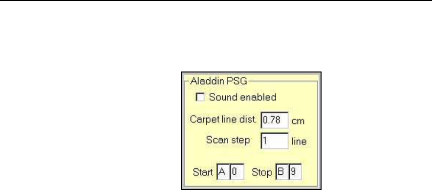
Step 3 in Aladdin PSG mode, you can select the acquisition
coordinates (see Fig. 4-4).
Fig. 4-4 –Aladdin PSG field
• The following parameters can be selected in this field:
Sound enabled: activates acoustic sound during
acquisition;
Carpet line dist.: distance between two lines on the PSG
carpet.
Scan step: setting the value “n” in this field, you decide
to perform 1 scan every “n” lines on the PSG.
Start/Stop: these are the initial and final scan coordinates
to be performed on the PSG carpet.
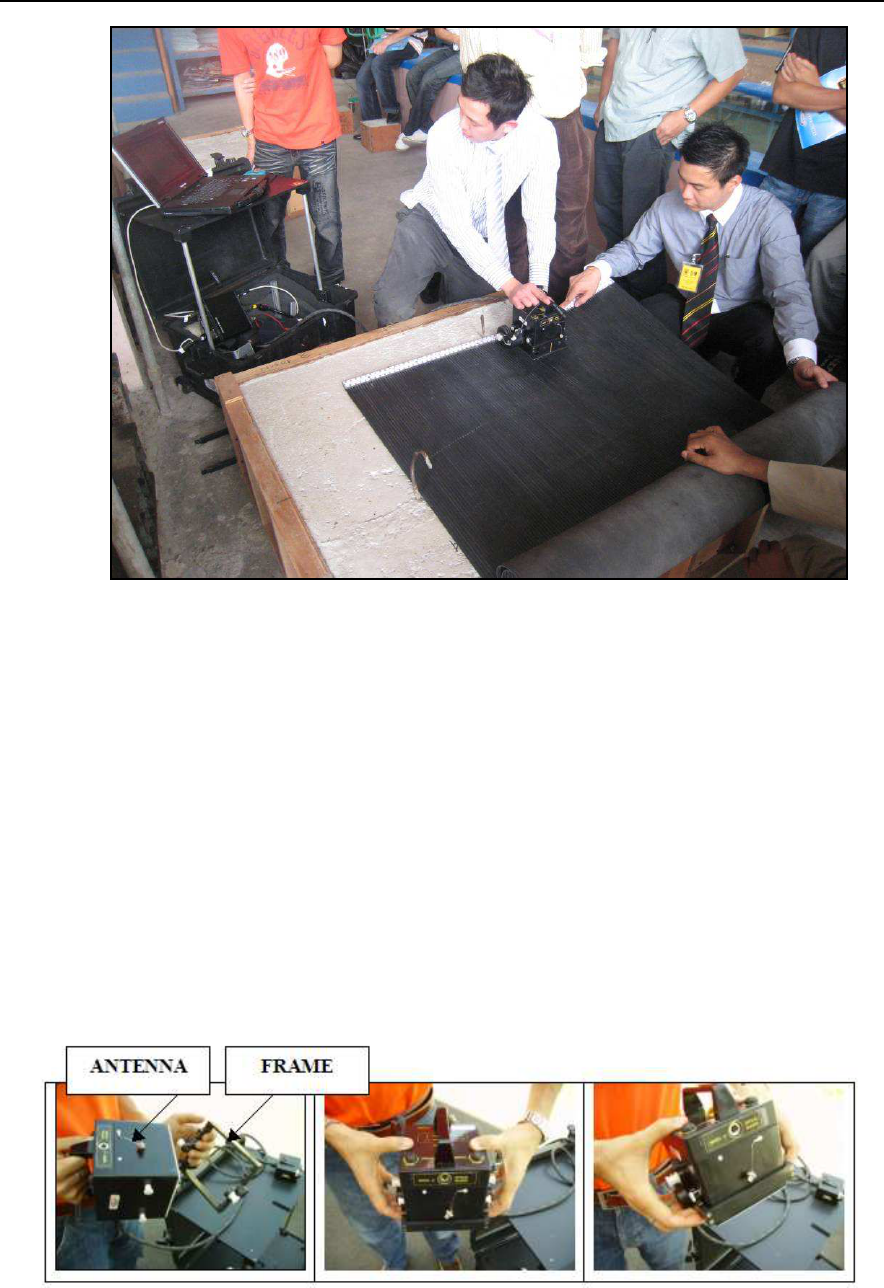
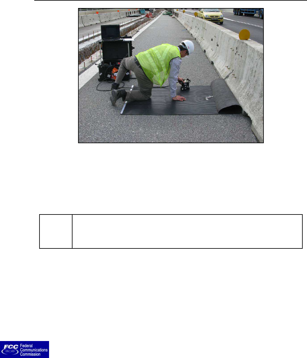
4.3 Work procedure using the Aladdin system
4.3.1 "Automatic" mode
Step 1: Assemble the system and place the pad on the surface to be
investigated (see Fig. 4-5).
IDS Ingegneria Dei Sistemi S.p.A. Protocol: MN/2009/061 - Rev. 1.1
“ALADDIN” STRUCTURE KIT User
Manual
29
/
32
Fig. 4-5 – Aladdin system
Step 2: Start the K2 SW, perform the calibration and set the Aladdin
structures kit parameters.
NOTE!
Using a bipolar antenna, only longitudinal scans must be
performed; for a single high frequency antenna, perform both
longitudinal and transversal scans
Step 3: Position the antenna on the initial preset coordinate in the L
(or T) direction and carefully position the antenna until the acoustic
signal stops.
Step 4A (Standard System): Press one of the START buttons placed
on the handle or directly on the antenna ; a special acoustic signal will
confirm that the START button has been pressed.
Step 4B (US System): Press one of the START buttons placed on the
handle or directly on the antenna and keep it pressed; a special
acoustic signal will confirm that the START button has been pressed.
Releasing the button, will stop the collection after 10 sec.

IDS Ingegneria Dei Sistemi S.p.A. Protocol: MN/2009/061 - Rev. 1.1
“ALADDIN” STRUCTURE KIT User
Manual
30
/
32
4.3.2 “Manual” Mode
Steps 1-4: Follow the same procedure described for "Automatic"
mode above.
Step 5: Acquisition starts when you press the START button,
independently of the position of the first horizontal line encountered.
Step 6A (Standard System): Insertion of User Markers during
scanning is performed by rapidly pressing the START button.
Step 6B (US System): Insertion of User Markers during scanning is
performed by rapidly releasing and pressing again the START
button.
Step 7A (Standard System): The scan is STOPPED by keeping the
START button pressed
Step 7B (US System): The scan is STOPPED by releasing the START
button
NOTE!
The system keeps control of data quality (Tolerance
) in both
Automatic and Manual mode. In fact, if this tolerance is
respected, a confirmation acoustic signal is activated; if the
tolerance exceeds the pre-
set percentage during the scan,
an error acoustic signal is heard, the scan isn't saved and you
have to repeat it.
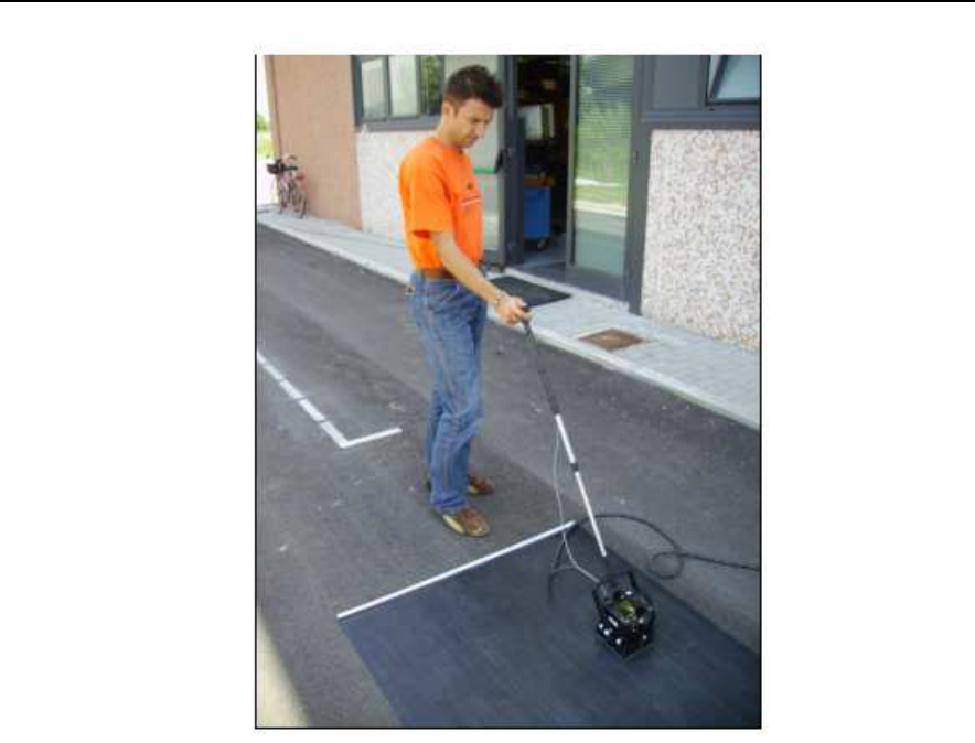
4.3.3 “Manual (no check)” Mode
Step 1-7: In this case the user must use the PSG carpet –Pad Survey
Guide Guide (Fig. 4-6) with the slide applied under the frame (see Par.
3.2.3).
IDS Ingegneria Dei Sistemi S.p.A. Protocol: MN/2009/061 - Rev. 1.1
“ALADDIN” STRUCTURE KIT User
Manual
31
/
32
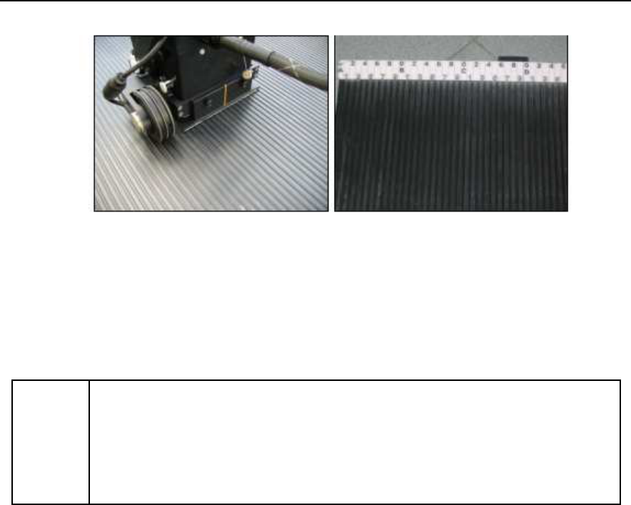
Fig. 4-6 – PSG Carpet
The PSG carpet holds alternated upper and lower guides in order to
make the slide perfectly fit and for the antenna to realize straight
scans. Also the slide holds a special film on its external surface
removing to the minimum the friction during the drag of the antenna
on PSG. Finally the PSG holds on its edge a graduated horizontal pole
with the indication of numbers and letters in progressive sequence, in
order to give to the user a reference point at the beginning of the scan
(Fig. 4-7).
IDS Ingegneria Dei Sistemi S.p.A. Protocol: MN/2009/061 - Rev. 1.1
“ALADDIN” STRUCTURE KIT User
Manual
32
/
32
Fig. 4-7 – Features of PSG and slide
Follow the same operative procedure used in the "Manual" procedure
described above.
NOTE!
The main difference with respect to the "Manual" mode consists
in the absence of the Tolerance control factor, therefore you are
free to choose how long the scan should be (Length). This mode
is useful when scans of different lengths have to
be performed.