IEI Integration 410UPC-V312 PANEL PC User Manual UPC V312 D525 Panel PC
IEI Integration Corp. PANEL PC UPC V312 D525 Panel PC
Contents
- 1. UPC-V312-D525_User Manual_Rev1_part3
- 2. UPC-V312-D525_User Manual_Rev1_part2
UPC-V312-D525_User Manual_Rev1_part3
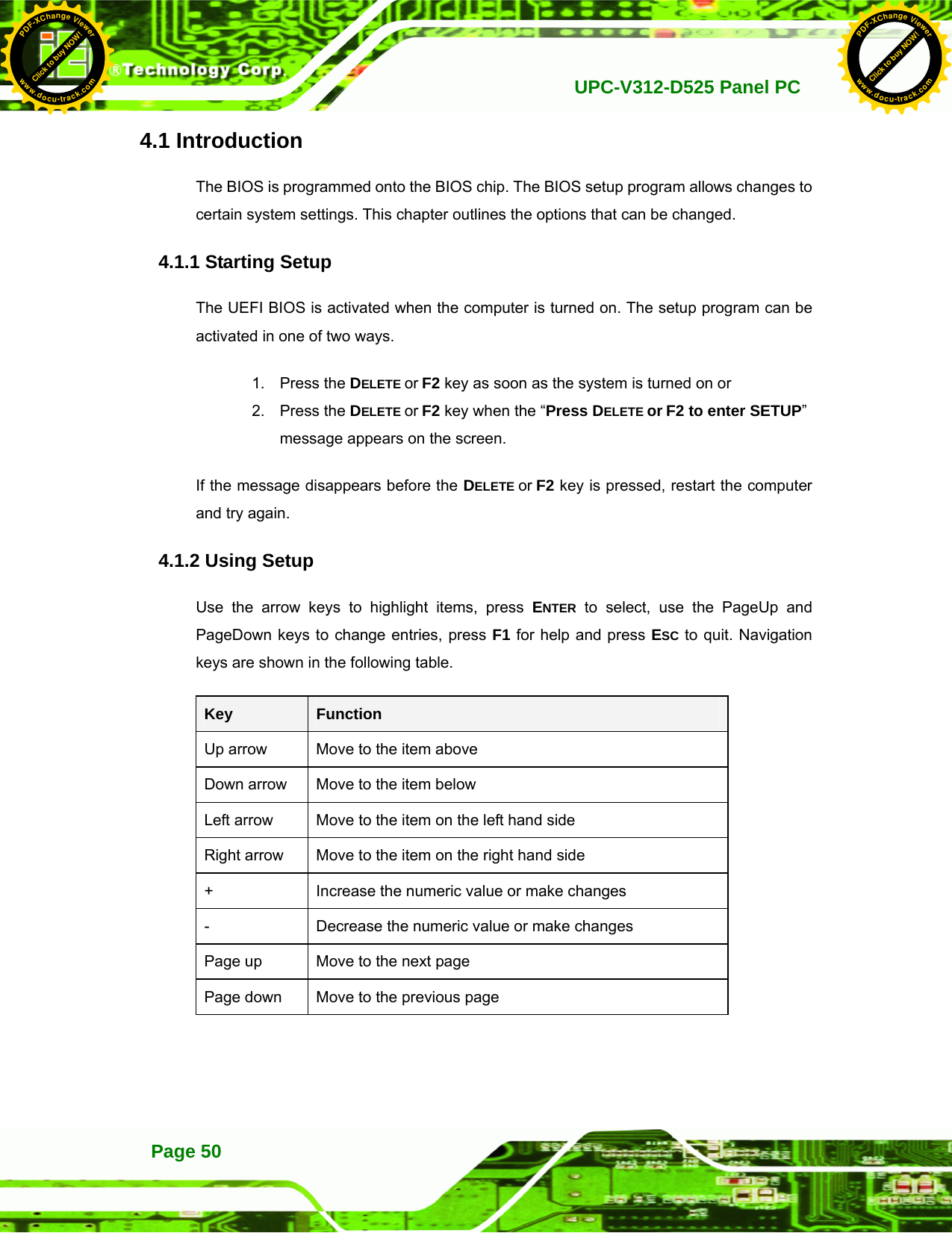
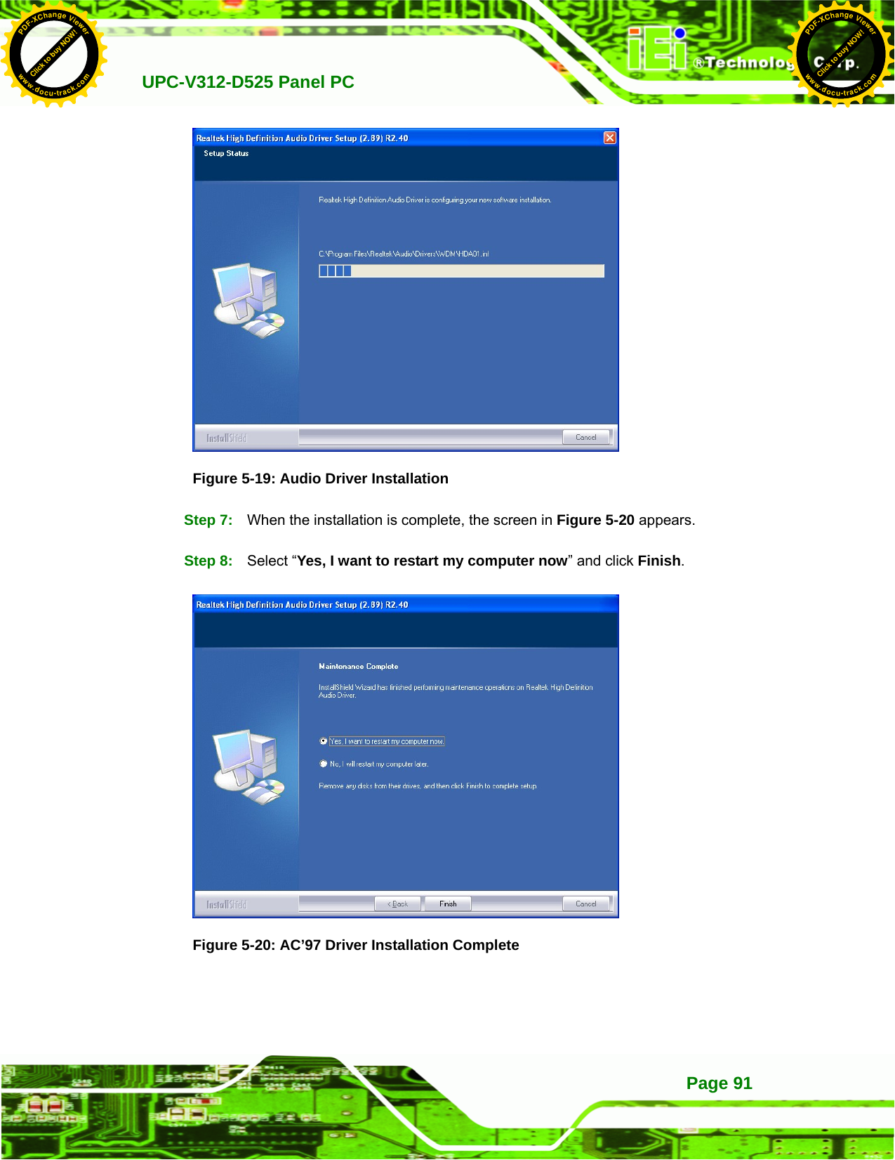
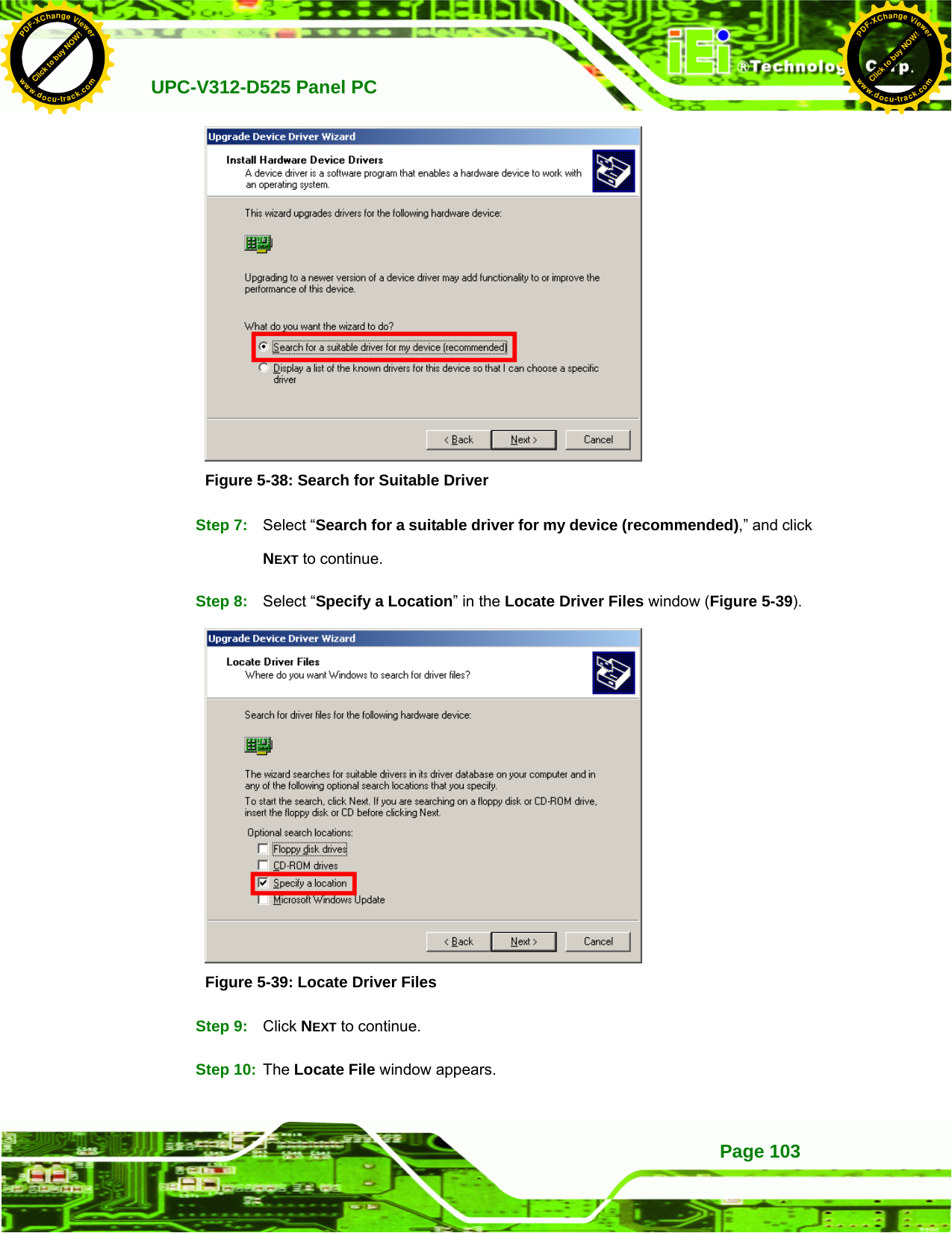
![UPC-V312-D525 Panel PCPage 52 4.2 Main The Main BIOS menu (BIOS Menu 1) appears when the BIOS Setup program is entered. The Main menu gives an overview of the basic system information. Aptio Setup Utility – Copyright (C) 2010 American Megatrends, Inc. Main Advanced Chipset Boot Save & Exit BIOS Information BIOS Vendor American Megatrends Core Version 4.6.4.0 0.20 Compliency UEFI 2.0 Project Version SC80AR13.ROM Build Date 08/03/2011 16:42:05 IWDD Vender ICP IWDD Version SC80ER12.bin System Date [Tue 05/06/2008] System Time [14:20:27] Access Level Administrator Set the Time. Use Tab to switch between Time elements. ---------------------- ÅÆ: Select Screen ↑ ↓: Select Item Enter Select +/-: Change Opt. F1: General Help F2: Previous Values F3: Optimized DefaultsF4: Save & Exit ESC: Exit Version 2.02.1205. Copyright (C) 2010 American Megatrends, Inc. BIOS Menu 1: Main Î BIOS Information The BIOS Information lists a brief summary of the BIOS. The fields in BIOS Information cannot be changed. The items shown in the system overview include: BIOS Vendor: Installed BIOS vendor Core Version: Current BIOS version Compliency: compliant UEFI specification version Project Version: the board version Build Date: Date the current BIOS version was made Î System Date [xx/xx/xx] Use the System Date option to set the system date. Manually enter the day, month and year. Click to buy NOW!PDF-XChange Viewerwww.docu-track.comClick to buy NOW!PDF-XChange Viewerwww.docu-track.com](https://usermanual.wiki/IEI-Integration/410UPC-V312.UPC-V312-D525-User-Manual-Rev1-part3/User-Guide-1842396-Page-4.png)
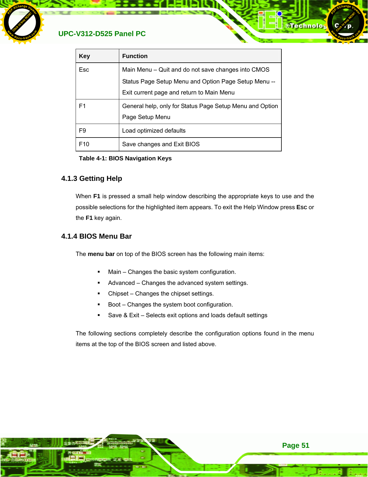
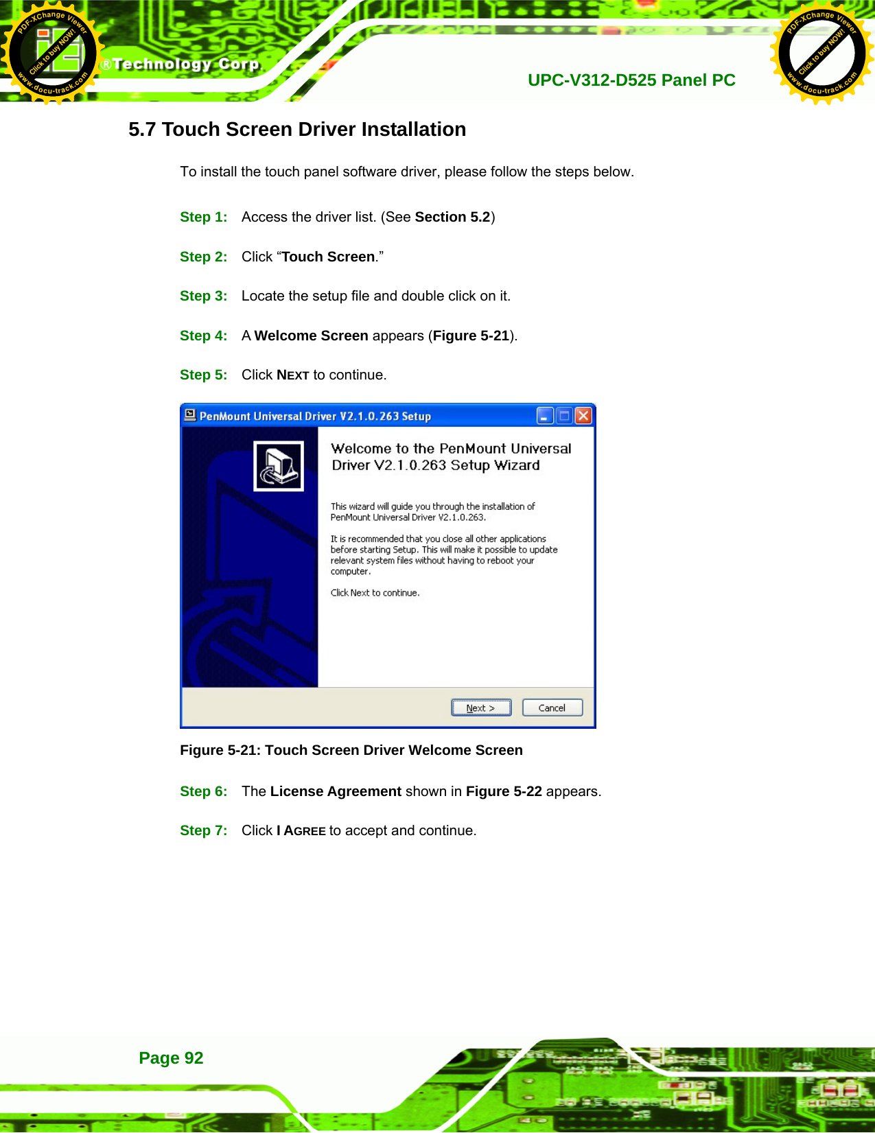
![UPC-V312-D525 Panel PC Page 53Î System Time [xx:xx:xx] Use the System Time option to set the system time. Manually enter the hours, minutes and seconds. 4.3 Advanced Use the Advanced menu (BIOS Menu 2) to configure the CPU and peripheral devices through the following sub-menus: WARNING! Setting the wrong values in the sections below may cause the system to malfunction. Make sure that the settings made are compatible with the hardware. Aptio Setup Utility – Copyright (C) 2010 American Megatrends, Inc. Main Advanced Chipset Boot Save & Exit > ACPI Settings > CPU Configuration > IDE Configuration > USB Configuration > Super IO Configuration > H/M Monitor > Serial Port Console Redirection > iEi Feature System ACPI Parameters ---------------------- ÅÆ: Select Screen ↑ ↓: Select Item Enter Select +/-: Change Opt. F1: General Help F2: Previous Values F3: Optimized Defaults F4: Save & Exit ESC: Exit Version 2.02.1205. Copyright (C) 2010 American Megatrends, Inc. BIOS Menu 2: Advanced 4.3.1 ACPI Settings The ACPI Settings menu (BIOS Menu 3) configures the Advanced Configuration and Power Interface (ACPI) options. Click to buy NOW!PDF-XChange Viewerwww.docu-track.comClick to buy NOW!PDF-XChange Viewerwww.docu-track.com](https://usermanual.wiki/IEI-Integration/410UPC-V312.UPC-V312-D525-User-Manual-Rev1-part3/User-Guide-1842396-Page-5.png)
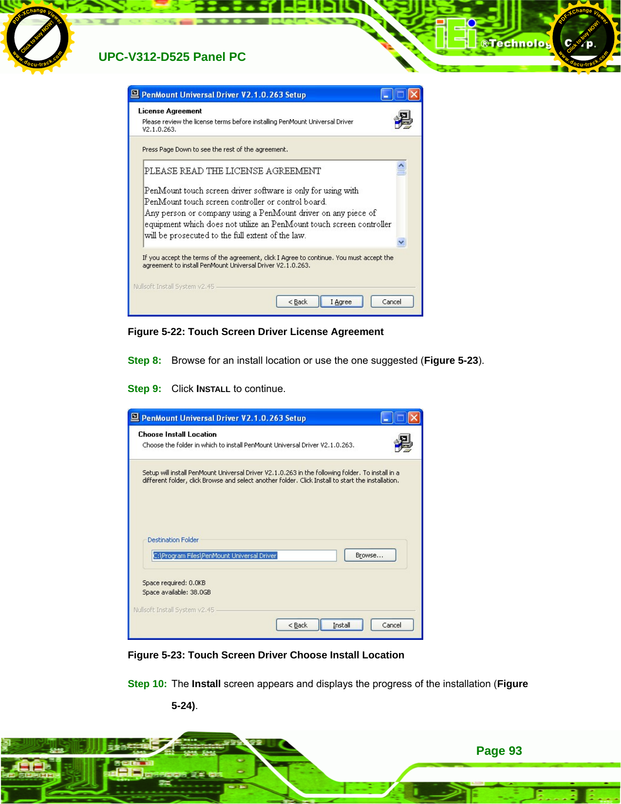
![UPC-V312-D525 Panel PCPage 54 Aptio Setup Utility – Copyright (C) 2010 American Megatrends, Inc. Advanced ACPI Sleep State [S1 (CPU Stop Clock)] Select the highest ACPI sleep state the system will enter, when the SUSPEND button is pressed. ---------------------- ÅÆ: Select Screen ↑ ↓: Select Item Enter Select F1 General Help F2 Previous Values F3 Optimized Defaults F4 Save ESC Exit Version 2.02.1205. Copyright (C) 2010 American Megatrends, Inc. BIOS Menu 3: ACPI Configuration Î ACPI Sleep State [S1 (CPU Stop Clock)] Use the ACPI Sleep State option to specify the sleep state the system enters when it is not being used. Î S1 (CPU Stop Clock) DEFAULT The system enters S1(POS) sleep state. The system appears off. The CPU is stopped; RAM is refreshed; the system is running in a low power mode. Î S3 (Suspend to RAM) The caches are flushed and the CPU is powered off. Power to the RAM is maintained. The computer returns slower to a working state, but more power is saved. Click to buy NOW!PDF-XChange Viewerwww.docu-track.comClick to buy NOW!PDF-XChange Viewerwww.docu-track.com](https://usermanual.wiki/IEI-Integration/410UPC-V312.UPC-V312-D525-User-Manual-Rev1-part3/User-Guide-1842396-Page-6.png)
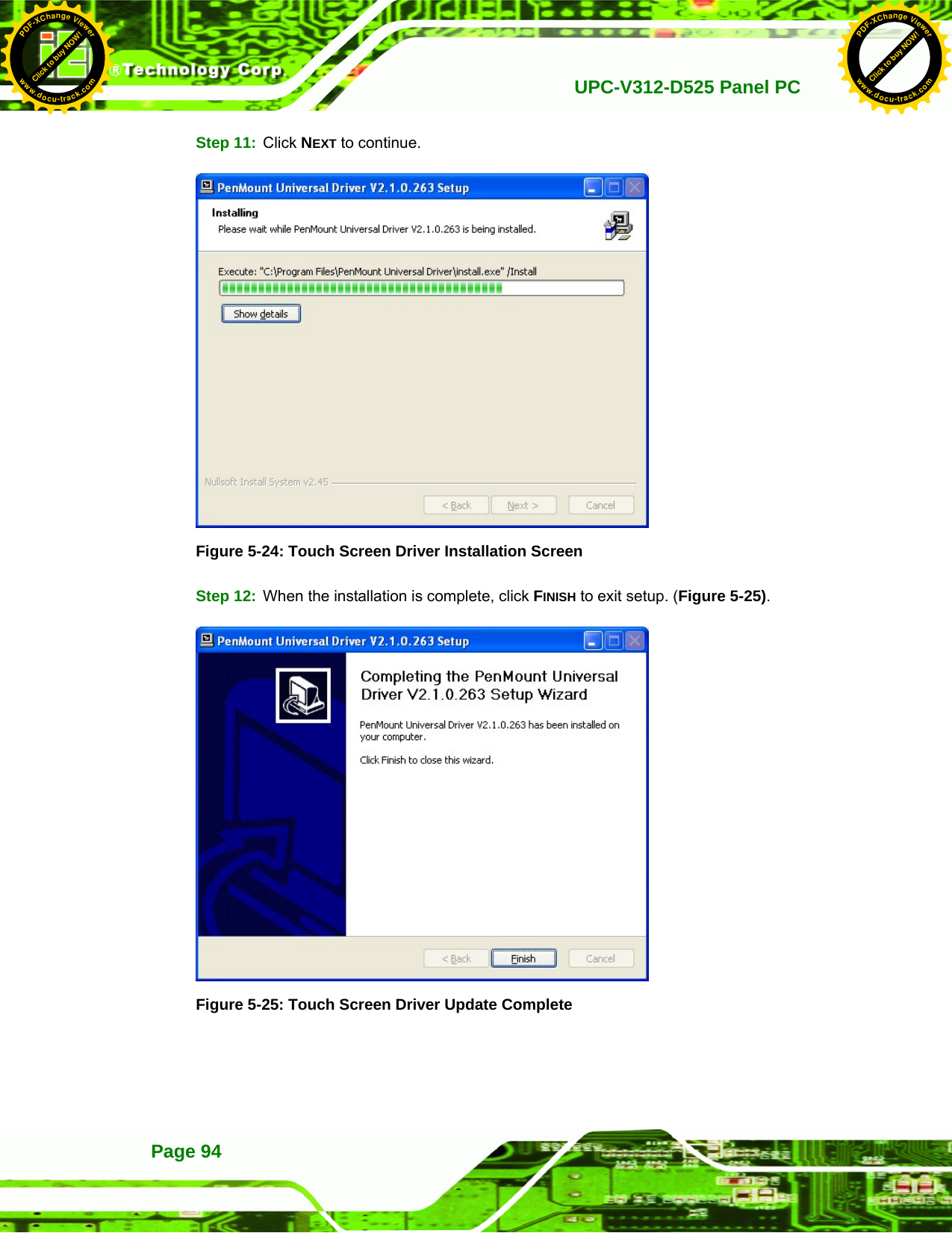
![UPC-V312-D525 Panel PC Page 554.3.2 CPU Configuration Use the CPU Configuration menu (BIOS Menu 4) to view detailed CPU specifications and configure the CPU. Aptio Setup Utility – Copyright (C) 2010 American Megatrends, Inc. Advanced CPU Configuration Processor Type Intel(R) Atom(TM) CPU D525 @ 1.80GHz EMT64 Supported Processor Speed 1800 MHz System Bus Speed 800 MHz Ratio Status 9 Actual Ratio 9 Processor Stepping 106ca Microcode Revision 263 L1 Cache RAM 2x56 k L2 Cache RAM 2x512 k Processor Cores Dual Hyper-Threading Supported Hyper-Threading [Enabled] ---------------------- ÅÆ: Select Screen ↑ ↓: Select Item Enter Select F1 General Help F2 Previous Values F3 Optimized Defaults F4 Save ESC Exit Version 2.02.1205. Copyright (C) 2010 American Megatrends, Inc. BIOS Menu 4: CPU Configuration The CPU Configuration menu (BIOS Menu 4) lists the following CPU details: Processor Type: Lists the brand name of the CPU being used EMT64: Indicates if EM64T is supported by the CPU. Processor Speed: Lists the CPU processing speed System Bus Speed: Lists the system bus speed Ratio Status: Lists the ratio status Actual Ratio: Lists the actual ratio Processor Stepping: Lists the CPU processing stepping Microcode Revision: Lists the microcode revision L1 Cache RAM: Lists the amount of storage space on the L1 Cache L2 Cache RAM: Lists the amount of storage space on the L2 Cache Processor Core: Lists the number of the processor cores Hyper-Threading: Indicates if Hyper-Threading is supported by the CPU. Hyper Threading Function [Enabled] Click to buy NOW!PDF-XChange Viewerwww.docu-track.comClick to buy NOW!PDF-XChange Viewerwww.docu-track.com](https://usermanual.wiki/IEI-Integration/410UPC-V312.UPC-V312-D525-User-Manual-Rev1-part3/User-Guide-1842396-Page-7.png)
![UPC-V312-D525 Panel PCPage 56 Use the Hyper Threading function to enable or disable the CPU hyper threading function. Î Disabled Disables the use of hyper threading technology Î Enabled DEFAULT Enables the use of hyper threading technology 4.3.3 IDE Configuration Use the IDE Configuration menu (BIOS Menu 5) to change and/or set the configuration of the IDE or SATA devices installed in the system. Aptio Setup Utility – Copyright (C) 2010 American Megatrends, Inc. Advanced PATA Slave No Present ATA/IDE Configuration [Compatible] Legacy IDE Channels [PATA Only] Select ATA/IDE Configuration --------------------- ÅÆ: Select Screen ↑ ↓: Select Item Enter Select F1 General Help F2 Previous Values F3 Optimized Defaults F4 Save ESC Exit Version 2.02.1205. Copyright (C) 2010 American Megatrends, Inc. BIOS Menu 5: IDE Configuration Î ATA/IDE Configurations [Compatible] Use the ATA/IDE Configurations option to configure the ATA/IDE controller. Î Disabled Disables the on-board ATA/IDE controller. Î Compatible DEFAULT Configures the on-board ATA/IDE controller to be in compatible mode. In this mode, a SATA channel will replace one of the IDE channels. This mode supports up to 4 storage devices. Click to buy NOW!PDF-XChange Viewerwww.docu-track.comClick to buy NOW!PDF-XChange Viewerwww.docu-track.com](https://usermanual.wiki/IEI-Integration/410UPC-V312.UPC-V312-D525-User-Manual-Rev1-part3/User-Guide-1842396-Page-8.png)
![UPC-V312-D525 Panel PC Page 57Î Enhanced Configures the on-board ATA/IDE controller to be in Enhanced mode. In this mode, IDE channels and SATA channels are separated. This mode supports up to 6 storage devices. Some legacy OS do not support this mode. Î Legacy IDE Channels [PATA Only] Î PATA Only Only the PATA drives are enabled. 4.3.4 USB Configuration Use the USB Configuration menu (BIOS Menu 6) to read USB configuration information and configure the USB settings. Aptio Setup Utility – Copyright (C) 2010 American Megatrends, Inc. Advanced USB Configuration USB Devices: 1 Keyboard Legacy USB Support [Enabled] Enables Legacy USB support. AUTO option disables legacy support if no USB devices are connected. DISABLE option will keep USB devices available only for EFI applications. --------------------- ÅÆ: Select Screen ↑ ↓: Select Item Enter Select F1 General Help F2 Previous Values F3 Optimized Defaults F4 Save ESC Exit Version 2.02.1205. Copyright (C) 2010 American Megatrends, Inc. BIOS Menu 6: USB Configuration Î USB Devices The USB Devices Enabled field lists the USB devices that are enabled on the system Click to buy NOW!PDF-XChange Viewerwww.docu-track.comClick to buy NOW!PDF-XChange Viewerwww.docu-track.com](https://usermanual.wiki/IEI-Integration/410UPC-V312.UPC-V312-D525-User-Manual-Rev1-part3/User-Guide-1842396-Page-9.png)
![UPC-V312-D525 Panel PCPage 58 Î Legacy USB Support [Enabled] Use the Legacy USB Support BIOS option to enable USB mouse and USB keyboard support. Normally if this option is not enabled, any attached USB mouse or USB keyboard does not become available until a USB compatible operating system is fully booted with all USB drivers loaded. When this option is enabled, any attached USB mouse or USB keyboard can control the system even when there is no USB driver loaded onto the system. Î Enabled DEFAULT Legacy USB support enabled Î Disabled Legacy USB support disabled Î Auto Legacy USB support disabled if no USB devices are connected 4.3.5 Super IO Configuration Use the Super IO Configuration menu (BIOS Menu 7) to set or change the configurations for the FDD controllers, parallel ports and serial ports. Aptio Setup Utility – Copyright (C) 2010 American Megatrends, Inc. Advanced Super IO Configuration Super IO Chip Fintek F81865 > Serial Port 1 Configuration > Serial Port 2 Configuration > Serial Port 3 Configuration > Serial Port 4 Configuration > Serial Port 5 Configuration > Serial Port 6 Configuration Set Parameters of Serial Port 0 (COMA) --------------------- ÅÆ: Select Screen ↑ ↓: Select Item Enter Select F1 General Help F2 Previous Values F3 Optimized Defaults F4 Save ESC Exit Version 2.02.1205. Copyright (C) 2010 American Megatrends, Inc. BIOS Menu 7: Super IO Configuration Click to buy NOW!PDF-XChange Viewerwww.docu-track.comClick to buy NOW!PDF-XChange Viewerwww.docu-track.com](https://usermanual.wiki/IEI-Integration/410UPC-V312.UPC-V312-D525-User-Manual-Rev1-part3/User-Guide-1842396-Page-10.png)
![UPC-V312-D525 Panel PC Page 594.3.5.1 Serial Port n Configuration Use the Serial Port n Configuration menu (BIOS Menu 8) to configure the serial port n. Aptio Setup Utility – Copyright (C) 2010 American Megatrends, Inc. Advanced Serial Port 1 Configuration Serial Port [Enabled] Device Settings IO=3F8h; IRQ=4 Change Settings [Auto] Enable or Disable Serial Port (COM) --------------------- ÅÆ: Select Screen ↑ ↓: Select Item Enter Select F1 General Help F2 Previous Values F3 Optimized Defaults F4 Save ESC Exit Version 2.02.1205. Copyright (C) 2010 American Megatrends, Inc. BIOS Menu 8: Serial Port n Configuration Menu 4.3.5.1.1 Serial Port 1 Configuration Î Serial Port [Enabled] Use the Serial Port option to enable or disable the serial port. Î Disabled Disable the serial port Î Enabled DEFAULT Enable the serial port Î Change Settings [Auto] Use the Change Settings option to change the serial port IO port address and interrupt address. Î Auto DEFAULT The serial port IO port address and interrupt address are automatically detected. Click to buy NOW!PDF-XChange Viewerwww.docu-track.comClick to buy NOW!PDF-XChange Viewerwww.docu-track.com](https://usermanual.wiki/IEI-Integration/410UPC-V312.UPC-V312-D525-User-Manual-Rev1-part3/User-Guide-1842396-Page-11.png)
![UPC-V312-D525 Panel PCPage 60 Î IO=3F8h; IRQ=4 Serial Port I/O port address is 3F8h and the interrupt address is IRQ4 Î IO=3F8h; IRQ=3, 4 Serial Port I/O port address is 3F8h and the interrupt address is IRQ3, 4 Î IO=2F8h; IRQ=3, 4 Serial Port I/O port address is 2F8h and the interrupt address is IRQ3, 4 4.3.5.1.2 Serial Port 2 Configuration Î Serial Port [Enabled] Use the Serial Port option to enable or disable the serial port. Î Disabled Disable the serial port Î Enabled DEFAULT Enable the serial port Î Change Settings [Auto] Use the Change Settings option to change the serial port IO port address and interrupt address. Î Auto DEFAULT The serial port IO port address and interrupt address are automatically detected. Î IO=2F8h; IRQ=3 Serial Port I/O port address is 2F8h and the interrupt address is IRQ3 Î IO=3F8h; IRQ=3, 4 Serial Port I/O port address is 3F8h and the interrupt address is IRQ3, 4 Î IO=2F8h; IRQ=3, 4 Serial Port I/O port address is 2F8h and the interrupt address is IRQ3, 4 Click to buy NOW!PDF-XChange Viewerwww.docu-track.comClick to buy NOW!PDF-XChange Viewerwww.docu-track.com](https://usermanual.wiki/IEI-Integration/410UPC-V312.UPC-V312-D525-User-Manual-Rev1-part3/User-Guide-1842396-Page-12.png)
![UPC-V312-D525 Panel PC Page 614.3.5.1.3 Serial Port 3 Configuration Î Serial Port [Enabled] Use the Serial Port option to enable or disable the serial port. Î Disabled Disable the serial port Î Enabled DEFAULT Enable the serial port Î Change Settings [Auto] Use the Change Settings option to change the serial port IO port address and interrupt address. Î Auto DEFAULT The serial port IO port address and interrupt address are automatically detected. Î IO=3E8h; IRQ=11 Serial Port I/O port address is 3E8h and the interrupt address is IRQ11 Î IO=3E8h; IRQ=10, 11 Serial Port I/O port address is 3E8h and the interrupt address is IRQ10, 11 Î IO=2E8h; IRQ=10, 11 Serial Port I/O port address is 2E8h and the interrupt address is IRQ10, 11 4.3.5.1.4 Serial Port 4 Configuration Î Serial Port [Enabled] Use the Serial Port option to enable or disable the serial port. Î Disabled Disable the serial port Î Enabled DEFAULT Enable the serial port Click to buy NOW!PDF-XChange Viewerwww.docu-track.comClick to buy NOW!PDF-XChange Viewerwww.docu-track.com](https://usermanual.wiki/IEI-Integration/410UPC-V312.UPC-V312-D525-User-Manual-Rev1-part3/User-Guide-1842396-Page-13.png)
![UPC-V312-D525 Panel PCPage 62 Î Change Settings [Auto] Use the Change Settings option to change the serial port IO port address and interrupt address. Î Auto DEFAULT The serial port IO port address and interrupt address are automatically detected. Î IO=2E8h; IRQ=10 Serial Port I/O port address is 2E8h and the interrupt address is IRQ10 Î IO=3E8h; IRQ=10, 11 Serial Port I/O port address is 3E8h and the interrupt address is IRQ10, 11 Î IO=2E8h; IRQ=10, 11 Serial Port I/O port address is 2E8h and the interrupt address is IRQ10, 11 4.3.5.1.5 Serial Port 5 Configuration Î Serial Port [Enabled] Use the Serial Port option to enable or disable the serial port. Î Disabled Disable the serial port Î Enabled DEFAULT Enable the serial port Î Change Settings [Auto] Use the Change Settings option to change the serial port IO port address and interrupt address. Î Auto DEFAULT The serial port IO port address and interrupt address are automatically detected. Î IO=2E0h; IRQ=7 Serial Port I/O port address is 2E0h and the interrupt address is IRQ7 Click to buy NOW!PDF-XChange Viewerwww.docu-track.comClick to buy NOW!PDF-XChange Viewerwww.docu-track.com](https://usermanual.wiki/IEI-Integration/410UPC-V312.UPC-V312-D525-User-Manual-Rev1-part3/User-Guide-1842396-Page-14.png)
![UPC-V312-D525 Panel PC Page 63Î IO=3F8h; IRQ=3, 4, 5, 6, 7, 10, 11, 12 Serial Port I/O port address is 3F8h and the interrupt address is IRQ3, 4, 5, 6, 7, 10, 11, 12 Î IO=2F8h; IRQ=3, 4, 5, 6, 7, 10, 11, 12 Serial Port I/O port address is 2F8h and the interrupt address is IRQ3, 4, 5, 6, 7, 10, 11, 12 Î IO=3E8h; IRQ=3, 4, 5, 6, 7, 10, 11, 12 Serial Port I/O port address is 3E8h and the interrupt address is IRQ3, 4, 5, 6, 7, 10, 11, 12 Î IO=2E8h; IRQ=3, 4, 5, 6, 7, 10, 11, 12 Serial Port I/O port address is 2E8h and the interrupt address is IRQ3, 4, 5, 6, 7, 10, 11, 12 Î IO=2E0h; IRQ=3, 4, 5, 6, 7, 10, 11, 12 Serial Port I/O port address is 2E0h and the interrupt address is IRQ3, 4, 5, 6, 7, 10, 11, 12 4.3.5.1.6 Serial Port 6 Configuration Î Serial Port [Enabled] Use the Serial Port option to enable or disable the serial port. Î Disabled Disable the serial port Î Enabled DEFAULT Enable the serial port Î Change Settings [Auto] Use the Change Settings option to change the serial port IO port address and interrupt address. Click to buy NOW!PDF-XChange Viewerwww.docu-track.comClick to buy NOW!PDF-XChange Viewerwww.docu-track.com](https://usermanual.wiki/IEI-Integration/410UPC-V312.UPC-V312-D525-User-Manual-Rev1-part3/User-Guide-1842396-Page-15.png)

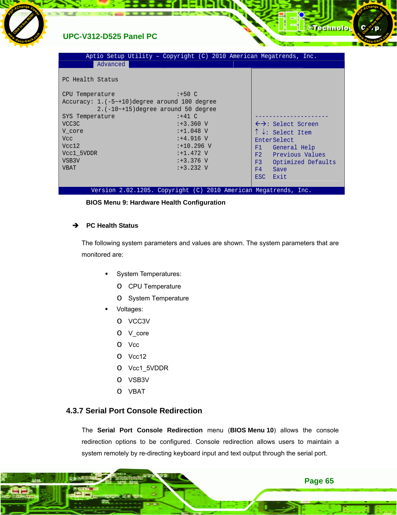
![UPC-V312-D525 Panel PCPage 66 Aptio Setup Utility – Copyright (C) 2010 American Megatrends, Inc. Advanced COM1 Console Redirection [Enabled] > Console Redirection Settings COM3 Console Redirection [Disabled] > Console Redirection Settings COM4 Console Redirection [Disabled] > Console Redirection Settings Console Redirection Enable or Disable --------------------- ÅÆ: Select Screen ↑ ↓: Select Item Enter Select F1 General Help F2 Previous Values F3 Optimized Defaults F4 Save ESC Exit Version 2.02.1205. Copyright (C) 2010 American Megatrends, Inc. BIOS Menu 10: Serial Port Console Redirection Î Console Redirection [Disabled] Use Console Redirection option to enable or disable the console redirection function. Î Disabled DEFAULT Disabled the console redirection function Î Enabled Enabled the console redirection function 4.3.7.1 Console Redirection Settings Use the Console Redirection Settings menu (BIOS Menu 11) to configure console redirection settings of the specified serial port. This menu appears only when the Console Redirection is enabled. Click to buy NOW!PDF-XChange Viewerwww.docu-track.comClick to buy NOW!PDF-XChange Viewerwww.docu-track.com](https://usermanual.wiki/IEI-Integration/410UPC-V312.UPC-V312-D525-User-Manual-Rev1-part3/User-Guide-1842396-Page-18.png)
![UPC-V312-D525 Panel PC Page 67Aptio Setup Utility – Copyright (C) 2010 American Megatrends, Inc. Advanced COM1 Console Redirection Settings Terminal Type [ANSI] Bits per second [115200] Data Bits [8] Parity [None] Stop Bits [1] Console Redirection Enable or Disable --------------------- ÅÆ: Select Screen ↑ ↓: Select Item Enter Select F1 General Help F2 Previous Values F3 Optimized Defaults F4 Save ESC Exit Version 2.02.1205. Copyright (C) 2010 American Megatrends, Inc. BIOS Menu 11: Console Redirection Settings Î Terminal Type [ANSI] Use the Terminal Type option to specify the remote terminal type. Î VT100 The target terminal type is VT100 Î VT100+ The target terminal type is VT100+ Î VT-UTF8 The target terminal type is VT-UTF8 Î ANSI DEFAULT The target terminal type is ANSI Î Bits per second [115200] Use the Bits per second option to select serial port transmission speed. The speed must match on the other side. Long or noisy lines may require lower speeds. The options include: 9600 19200 57600 115200 DEFAULT Click to buy NOW!PDF-XChange Viewerwww.docu-track.comClick to buy NOW!PDF-XChange Viewerwww.docu-track.com](https://usermanual.wiki/IEI-Integration/410UPC-V312.UPC-V312-D525-User-Manual-Rev1-part3/User-Guide-1842396-Page-19.png)
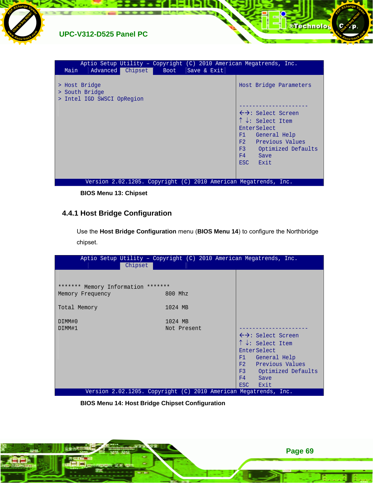
![UPC-V312-D525 Panel PCPage 68 4.3.8 IEI Feature Use the IEI Feature menu (BIOS Menu 12) to configure One Key Recovery function. BIOS SETUP UTILITY Main Advanced PCIPNP Boot Security Chipset Exit iEi Feature ⎯⎯⎯⎯⎯⎯⎯⎯⎯⎯⎯⎯⎯⎯⎯⎯⎯⎯⎯⎯⎯⎯⎯⎯⎯⎯⎯⎯⎯⎯⎯ Auto Recovery Function [Disabled] ÅÆ Select Screen ↑ ↓ Select Item Enter Go to SubScreen F1 General Help F10 Save and Exit ESC Exit v02.61 ©Copyright 1985-2006, American Megatrends, Inc. BIOS Menu 12: IEI Feature Î Auto Recovery Function [Disabled] Use the Auto Recovery Function BIOS option to enable or disable the auto recovery function of the IEI One Key Recovery. Î Disabled DEFAULT Auto recovery function disabled Î Enabled Auto recovery function enabled 4.4 Chipset Use the Chipset menu (BIOS Menu 13) to access the Northbridge and Southbridge configuration menus WARNING! Setting the wrong values for the Chipset BIOS selections in the Chipset BIOS menu may cause the system to malfunction. Click to buy NOW!PDF-XChange Viewerwww.docu-track.comClick to buy NOW!PDF-XChange Viewerwww.docu-track.com](https://usermanual.wiki/IEI-Integration/410UPC-V312.UPC-V312-D525-User-Manual-Rev1-part3/User-Guide-1842396-Page-20.png)
![UPC-V312-D525 Panel PCPage 70 4.4.2 South Bridge Configuration Use the South Bbridge Configuration menu (BIOS Menu 15) to configure the Southbridge chipset. Aptio Setup Utility – Copyright (C) 2010 American Megatrends, Inc. Chipset Auto Power Button Function [Enabled] High Definition Audio Controller [Enabled] USB Function [Enabled] USB 2.0(EHCI) Support [Enabled] Set Spread Spectrum function [Disabled] WIFI Support [Enabled] GPS Support [Disabled] MIC Support [Enabled] Auto Dimming Support [Enabled] High Definition Audio Controller --------------------- ÅÆ: Select Screen ↑ ↓: Select Item Enter Select F1 General Help F2 Previous Values F3 Optimized Defaults F4 Save ESC Exit Version 2.02.1205. Copyright (C) 2010 American Megatrends, Inc. BIOS Menu 15: South Bridge Chipset Configuration Î High Definition Audio Controller [Enabled] The High Definition Audio Controller option enables or disables the HD Audio controller. Î Enabled DEFAULT The onboard HD Audio controller is enabled Î Disabled The onboard HD Audio controller is disabled Î USB Function [Enabled] Use the USB Function BIOS option to enable or disable USB function support. Î Disabled USB function support disabled Î Enabled DEFAULT USB function support enabled Click to buy NOW!PDF-XChange Viewerwww.docu-track.comClick to buy NOW!PDF-XChange Viewerwww.docu-track.com](https://usermanual.wiki/IEI-Integration/410UPC-V312.UPC-V312-D525-User-Manual-Rev1-part3/User-Guide-1842396-Page-22.png)
![UPC-V312-D525 Panel PC Page 71Î Set Spread Spectrum function [Disabled] Use the Set Spread Spectrum function option to reduce the EMI. Excess EMI is generated when the system clock generator pulses have extreme values. Spreading the pulse spectrum modulates changes in the extreme values from spikes to flat curves, thus reducing the EMI. This benefit may in some cases be outweighed by problems with timing-critical devices, such as a clock-sensitive SCSI device. Î Disabled DEFAULT EMI not reduced Î Enabled EMI reduced Î WIFI Support [Enabled] Use the WIFI Support option to enable or disable the Wi-Fi function. Î Enabled DEFAULT Enables Wi-Fi function Î Disabled Disables Wi-Fi function Î GPS Support [Disabled] Use the GPS Support option to enable or disable the GPS function. Î Enabled Enables GPS function Î Disabled DEFAULT Disables GPS function Î MIC Support [Enabled] Use the MIC Support option to enable or disable the microphone. Î Enabled DEFAULT Enables microphone Î Disabled Disables microphone Î Auto Dimming Support [Enabled] Use the Auto Dimming Support option to enable or disable the auto dimming function. Î Enabled DEFAULT Enables auto dimming function Click to buy NOW!PDF-XChange Viewerwww.docu-track.comClick to buy NOW!PDF-XChange Viewerwww.docu-track.com](https://usermanual.wiki/IEI-Integration/410UPC-V312.UPC-V312-D525-User-Manual-Rev1-part3/User-Guide-1842396-Page-23.png)
![UPC-V312-D525 Panel PCPage 72 Î Disabled Disables auto dimming function 4.4.3 Intel IGD SWSCI OpRegion Use the Intel IGD SWSCI OpRegion menu (BIOS Menu 16) to configure the video device connected to the system. Aptio Setup Utility – Copyright (C) 2010 American Megatrends, Inc. Advanced Intel IGD SWSCI OpRegion Configuration DVMT Mode Select [DVMT Mode] DVMT/FIXED Memory [Maximum] IGD - Boot Type [VBIOS Default] LCD Panel Type [1024x768 18bit] Backlight Control [Inverted] Select DVMT Mode/Fixed Mode --------------------- ÅÆ: Select Screen ↑ ↓: Select Item Enter Select +/-: Change Opt. F1 General Help F2 Previous Values F3 Optimized DefaultsF4 Save ESC Exit Version 2.02.1205. Copyright (C) 2010 American Megatrends, Inc. BIOS Menu 16: Intel IGD SWSCI OpRegion Î DVMT Mode Select [DVMT Mode] Use the DVMT Mode Select option to select the Intel Dynamic Video Memory Technology (DVMT) operating mode. Î Fixed Mode A fixed portion of graphics memory is reserved as graphics memory. Î DVMT Mode DEFAULT Graphics memory is dynamically allocated according to the system and graphics needs. Î DVMT/FIXED Memory [Maximum] Use the DVMT/FIXED Memory option to specify the maximum amount of memory that can be allocated as graphics memory. Configuration options are listed below. 128 MB Click to buy NOW!PDF-XChange Viewerwww.docu-track.comClick to buy NOW!PDF-XChange Viewerwww.docu-track.com](https://usermanual.wiki/IEI-Integration/410UPC-V312.UPC-V312-D525-User-Manual-Rev1-part3/User-Guide-1842396-Page-24.png)
![UPC-V312-D525 Panel PC Page 73 256 MB Maximum Default Î IGD - Boot Type [VBIOS Default] Use the IGD - Boot Type option to select the display device used by the system when it boots. Configuration options are listed below. VBIOS Default DEFAULT CRT LFP CRT + LFP Î LCD Panel Type [1024x768 18bit] Use the LCD Panel Type option to select the type of flat panel connected to the system. Configuration option is listed below. 1024x768 18bit DEFAULT DVMT Mode Select [DVMT Mode] Î Backlight Control [Inverted] Use the Backlight Control option to select the backlight control mode. Î Normal Brightest at high voltage level Î Inverted DEFAULT Brightest at low voltage level Click to buy NOW!PDF-XChange Viewerwww.docu-track.comClick to buy NOW!PDF-XChange Viewerwww.docu-track.com](https://usermanual.wiki/IEI-Integration/410UPC-V312.UPC-V312-D525-User-Manual-Rev1-part3/User-Guide-1842396-Page-25.png)
![UPC-V312-D525 Panel PCPage 74 4.5 Boot Use the Boot menu (BIOS Menu 17) to configure system boot options. Aptio Setup Utility – Copyright (C) 2010 American Megatrends, Inc. Main Advanced Chipset Boot Save & Exit Boot Configuration Bootup NumLock State [On] Quiet Boot [Enabled] Launch PXE OpROM [Disabled] Boot Option Priorities Boot Option #1 [PATA: IEI Technolo..] Hard Drive BBS Priorities Select the keyboard NumLock state --------------------- ÅÆ: Select Screen ↑ ↓: Select Item Enter Select F1 General Help F2 Previous Values F3 Optimized Defaults F4 Save ESC Exit Version 2.02.1205. Copyright (C) 2010 American Megatrends, Inc. BIOS Menu 17: Boot Î Bootup NumLock State [On] Use the Bootup NumLock State BIOS option to specify if the number lock setting must be modified during boot up. Î On DEFAULT Allows the Number Lock on the keyboard to be enabled automatically when the computer system boots up. This allows the immediate use of the 10-key numeric keypad located on the right side of the keyboard. To confirm this, the Number Lock LED light on the keyboard is lit. Î Off Does not enable the keyboard Number Lock automatically. To use the 10-keys on the keyboard, press the Number Lock key located on the upper left-hand corner of the 10-key pad. The Number Lock LED on the keyboard lights up when the Number Lock is engaged. Click to buy NOW!PDF-XChange Viewerwww.docu-track.comClick to buy NOW!PDF-XChange Viewerwww.docu-track.com](https://usermanual.wiki/IEI-Integration/410UPC-V312.UPC-V312-D525-User-Manual-Rev1-part3/User-Guide-1842396-Page-26.png)
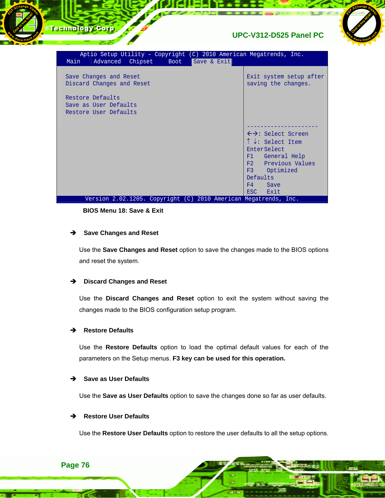
![UPC-V312-D525 Panel PC Page 75Î Quiet Boot [Enabled] Use the Quiet Boot BIOS option to select the screen display when the system boots. Î Disabled Normal POST messages displayed Î Enabled DEFAULT OEM Logo displayed instead of POST messages Î Launch PXE OpROM [Disabled] Use the Launch PXE OpROM option to enable or disable boot option for legacy network devices. Î Disabled DEFAULT Ignore all PXE Option ROMs Î Enabled Load PXE Option ROMs Î Boot Option #1 [PATA: IEI Technology Corp. ICF] Use the Boot Option #1 option to specify the boot sequence from the available devices. 4.6 Save & Exit Use the Save & Exit menu (BIOS Menu 18) to load default BIOS values, optimal failsafe values and to save configuration changes. Click to buy NOW!PDF-XChange Viewerwww.docu-track.comClick to buy NOW!PDF-XChange Viewerwww.docu-track.com](https://usermanual.wiki/IEI-Integration/410UPC-V312.UPC-V312-D525-User-Manual-Rev1-part3/User-Guide-1842396-Page-27.png)


![UPC-V312-D525 Panel PCPage 106 A.1 BIOS Configuration Options Below is a list of BIOS configuration options described in Chapter 664. BIOS Information .................................................................................................................52 System Date [xx/xx/xx]........................................................................................................52 System Time [xx:xx:xx].......................................................................................................53 ACPI Sleep State [S1 (CPU Stop Clock)] ...........................................................................54 ATA/IDE Configurations [Compatible]...............................................................................56 Legacy IDE Channels [PATA Only]....................................................................................57 USB Devices.........................................................................................................................57 Legacy USB Support [Enabled]..........................................................................................58 Serial Port [Enabled]............................................................................................................59 Change Settings [Auto].......................................................................................................59 Serial Port [Enabled]............................................................................................................60 Change Settings [Auto].......................................................................................................60 Serial Port [Enabled]............................................................................................................61 Change Settings [Auto].......................................................................................................61 Serial Port [Enabled]............................................................................................................61 Change Settings [Auto].......................................................................................................62 Serial Port [Enabled]............................................................................................................62 Change Settings [Auto].......................................................................................................62 Serial Port [Enabled]............................................................................................................63 Change Settings [Auto].......................................................................................................63 PC Health Status..................................................................................................................65 Console Redirection [Disabled] .........................................................................................66 Terminal Type [ANSI]...........................................................................................................67 Bits per second [115200].....................................................................................................67 Auto Recovery Function [Disabled]...................................................................................68 High Definition Audio Controller [Enabled] ......................................................................70 USB Function [Enabled]......................................................................................................70 Set Spread Spectrum function [Disabled].........................................................................71 WIFI Support [Enabled] .......................................................................................................71 GPS Support [Disabled] ......................................................................................................71 MIC Support [Enabled] ........................................................................................................71 Click to buy NOW!PDF-XChange Viewerwww.docu-track.comClick to buy NOW!PDF-XChange Viewerwww.docu-track.com](https://usermanual.wiki/IEI-Integration/410UPC-V312.UPC-V312-D525-User-Manual-Rev1-part3/User-Guide-1842396-Page-58.png)
![UPC-V312-D525 Panel PC Page 107 Auto Dimming Support [Enabled]......................................................................................71 DVMT Mode Select [DVMT Mode].......................................................................................72 DVMT/FIXED Memory [Maximum] ......................................................................................72 IGD - Boot Type [VBIOS Default]........................................................................................73 LCD Panel Type [1024x768 18bit].......................................................................................73 Backlight Control [Inverted]................................................................................................73 Bootup NumLock State [On]...............................................................................................74 Quiet Boot [Enabled] ...........................................................................................................75 Launch PXE OpROM [Disabled].........................................................................................75 Boot Option #1 [PATA: IEI Technology Corp. ICF]...........................................................75 Save Changes and Reset ....................................................................................................76 Discard Changes and Reset ...............................................................................................76 Restore Defaults ..................................................................................................................76 Save as User Defaults .........................................................................................................76 Restore User Defaults .........................................................................................................76 Click to buy NOW!PDF-XChange Viewerwww.docu-track.comClick to buy NOW!PDF-XChange Viewerwww.docu-track.com](https://usermanual.wiki/IEI-Integration/410UPC-V312.UPC-V312-D525-User-Manual-Rev1-part3/User-Guide-1842396-Page-59.png)

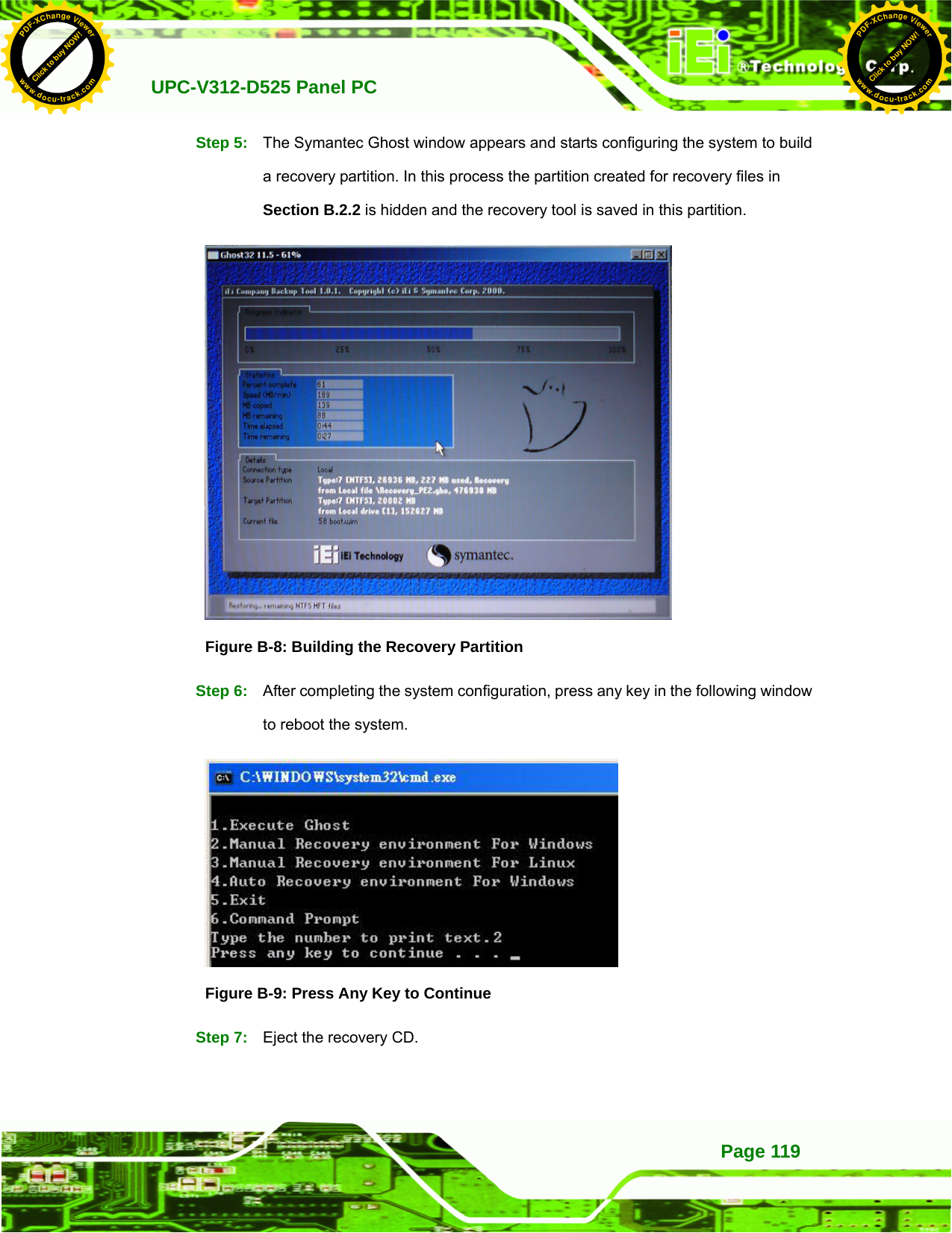
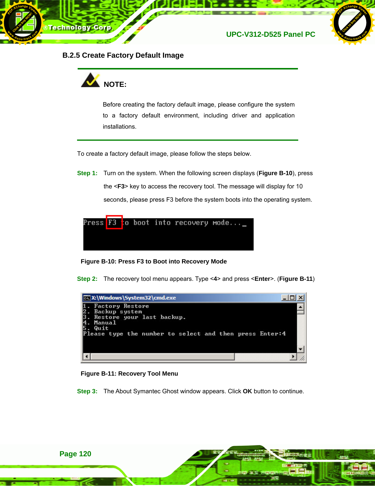
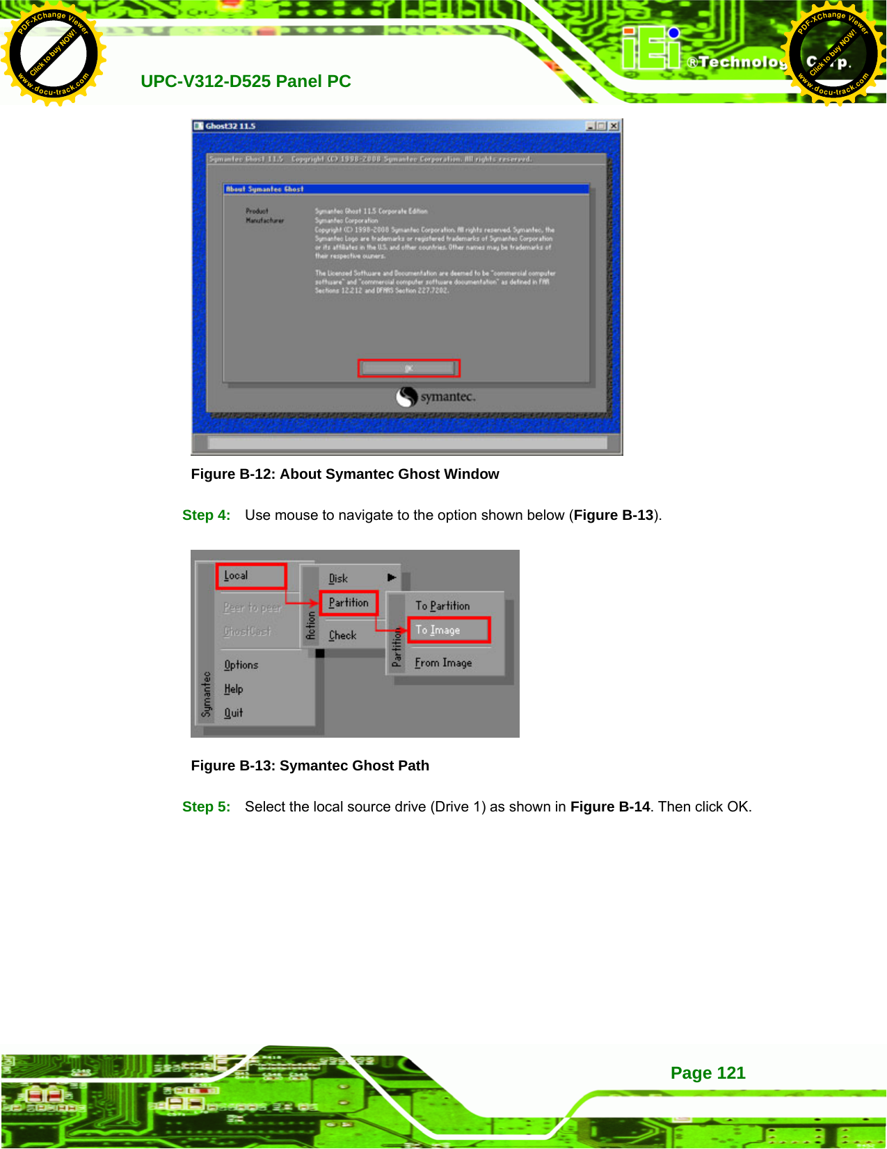
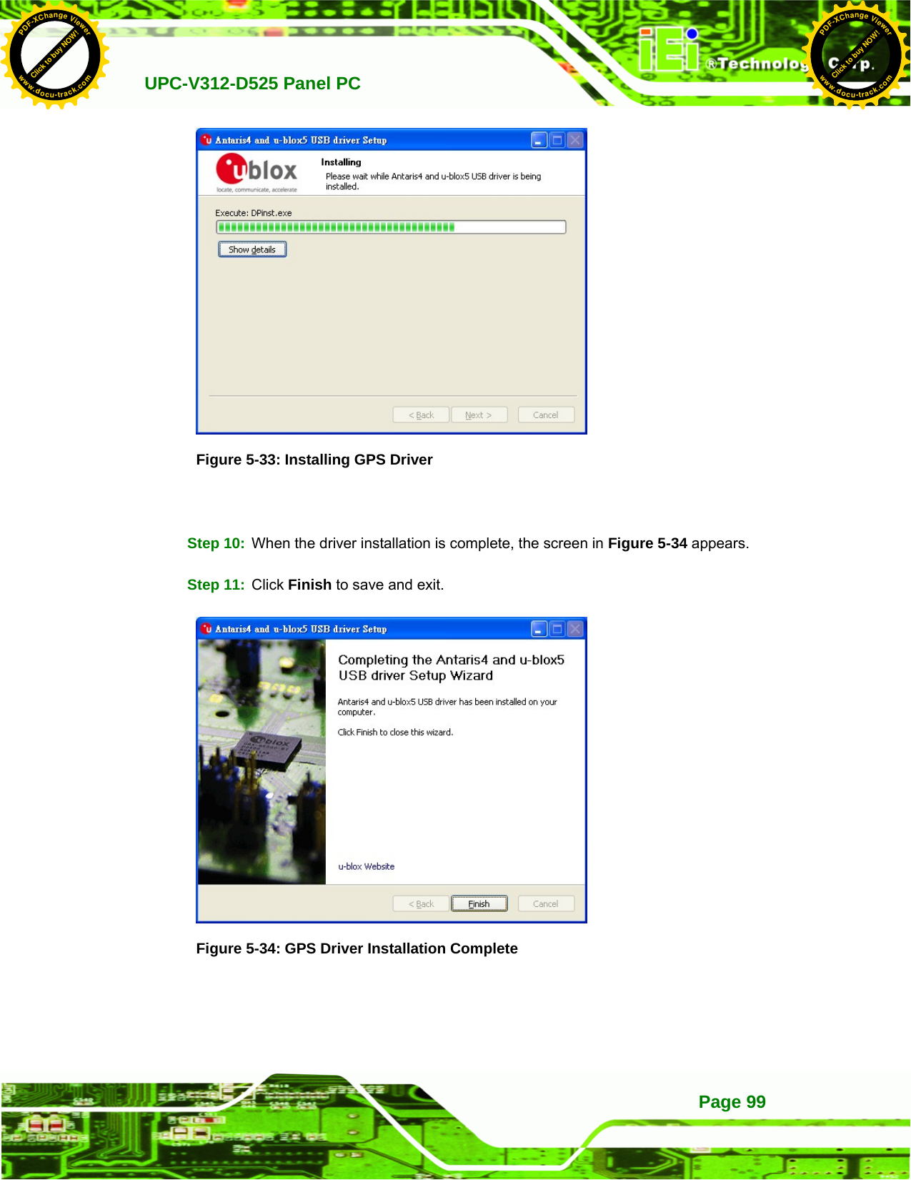
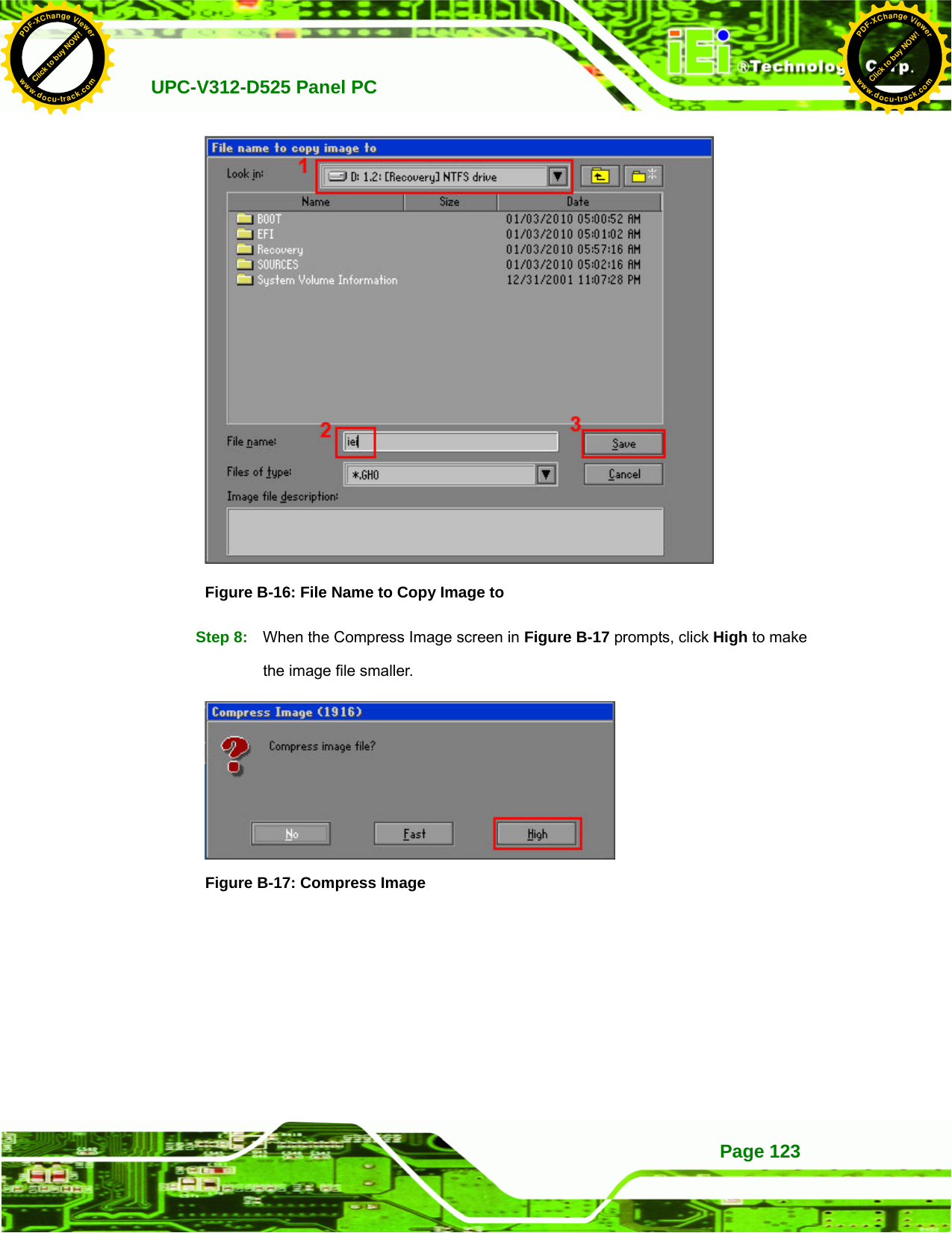
![UPC-V312-D525 Panel PCPage 122 Figure B-14: Select a Local Source Drive Step 6: Select a source partition (Part 1) from basic drive as shown in Figure B-15. Then click OK. Figure B-15: Select a Source Partition from Basic Drive Step 7: Select 1.2: [Recovery] NTFS drive and enter a file name called iei (Figure B-16). Click Save. The factory default image will then be saved in the selected recovery drive and named IEI.GHO. WARNING: The file name of the factory default image must be iei.GHO. Click to buy NOW!PDF-XChange Viewerwww.docu-track.comClick to buy NOW!PDF-XChange Viewerwww.docu-track.com](https://usermanual.wiki/IEI-Integration/410UPC-V312.UPC-V312-D525-User-Manual-Rev1-part3/User-Guide-1842396-Page-74.png)
![UPC-V312-D525 Panel PC Page 129BIOS SETUP UTILITY Main Advanced PCIPNP Boot Security Chipset Exit iEi Feature ⎯⎯⎯⎯⎯⎯⎯⎯⎯⎯⎯⎯⎯⎯⎯⎯⎯⎯⎯⎯⎯⎯⎯⎯⎯⎯⎯ Auto Recovery Function [Enabled] Recover from PXE [Disabled] ÅÆ Select Screen ↑ ↓ Select Item Enter Go to SubScreen F1 General Help F10 Save and Exit ESC Exit v02.61 ©Copyright 1985-2006, American Megatrends, Inc. BIOS Menu 19: IEI Feature Step 12: Save changes and restart the system. If the system encounters a Blue Screen of Death (BSoD) or a hang for around 10 minutes, it will automatically restore from the factory default image. Step 0: CAUTION: The auto recovery function can only apply on a Microsoft Windows system running the following OS versions: Windows XP Windows Vista Windows 7 B.4 Setup Procedure for Linux The initial setup procedure for Linux system is mostly the same with the procedure for Microsoft Windows. Please follow the steps below to setup recovery tool for Linux OS. Step 1: Hardware and BIOS setup. Refer to Section B.2.1. Click to buy NOW!PDF-XChange Viewerwww.docu-track.comClick to buy NOW!PDF-XChange Viewerwww.docu-track.com](https://usermanual.wiki/IEI-Integration/410UPC-V312.UPC-V312-D525-User-Manual-Rev1-part3/User-Guide-1842396-Page-81.png)
![UPC-V312-D525 Panel PC Page 143Modify: [image] comment = One Key Recovery path = /share/image browseable = yes writable = yes public = yes create mask = 0644 directory mask = 0755 Step 4: Edit “/etc/samba/smb.conf” for your environment. For example: Step 5: Modify the hostname #vi /etc/hostname Modify: RecoveryServer B.6.6 Setup a Client System for Auto Recovery Step 1: Configure the following BIOS options of the client system. Advanced → iEi Feature → Auto Recovery Function → Enabled Advanced → iEi Feature → Recover from PXE → Enabled Boot → Launch PXE OpROM → Enabled Click to buy NOW!PDF-XChange Viewerwww.docu-track.comClick to buy NOW!PDF-XChange Viewerwww.docu-track.com](https://usermanual.wiki/IEI-Integration/410UPC-V312.UPC-V312-D525-User-Manual-Rev1-part3/User-Guide-1842396-Page-95.png)