IEI Integration 410UPC-V312 PANEL PC User Manual UPC V312 D525 Panel PC
IEI Integration Corp. PANEL PC UPC V312 D525 Panel PC
Contents
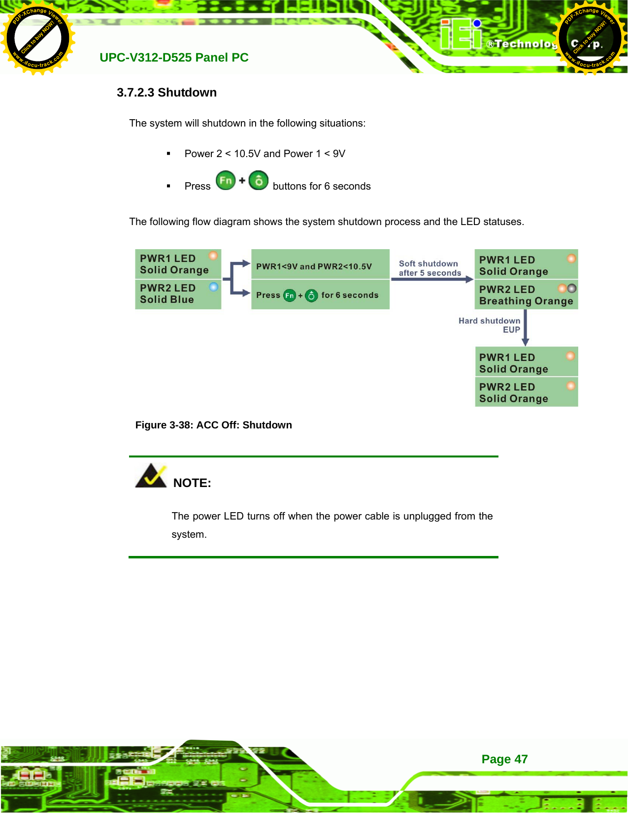
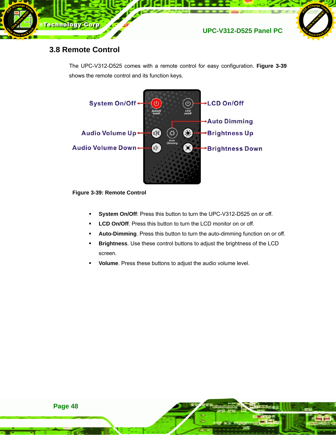
- 1. UPC-V312-D525_User Manual_Rev1_part3
- 2. UPC-V312-D525_User Manual_Rev1_part2
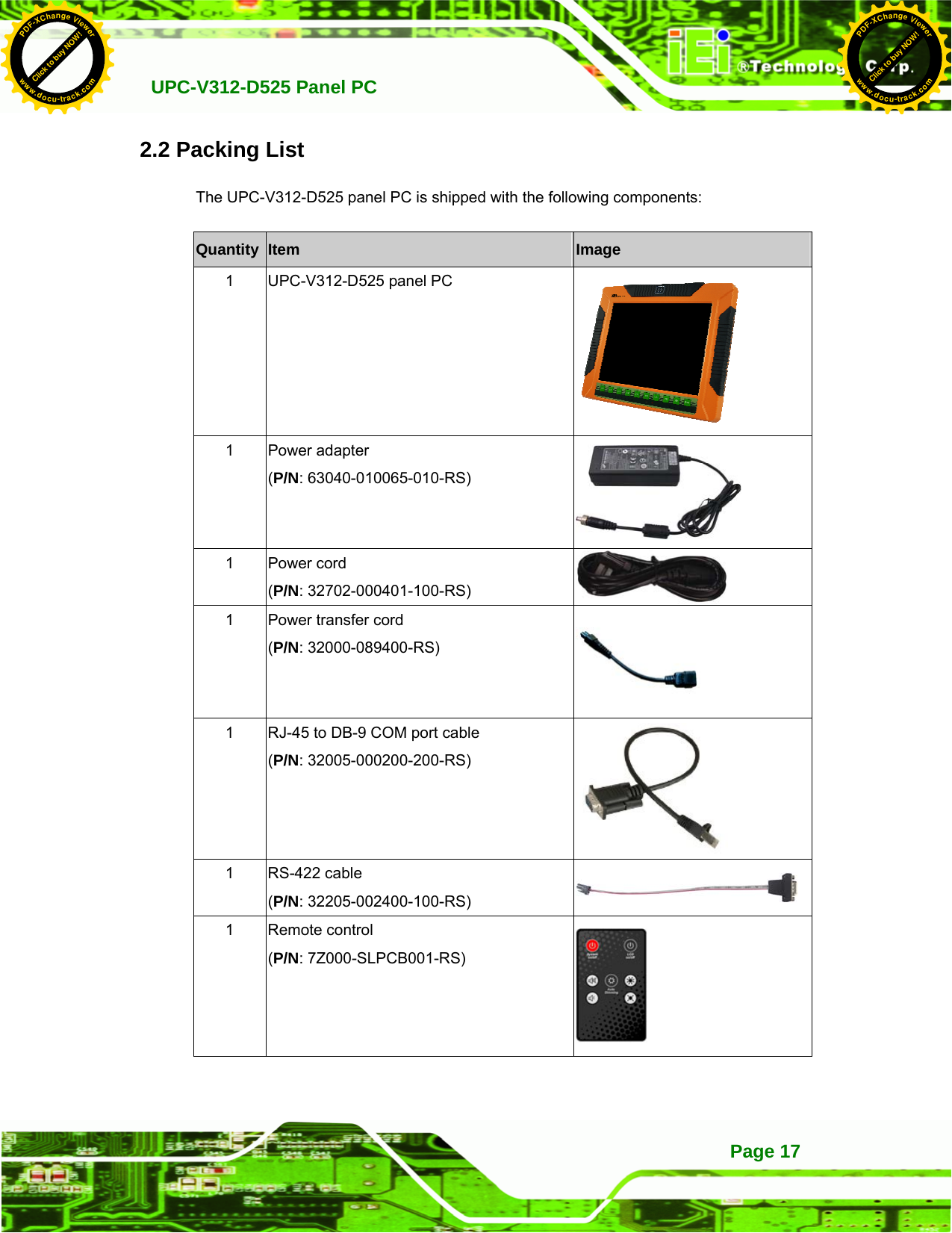
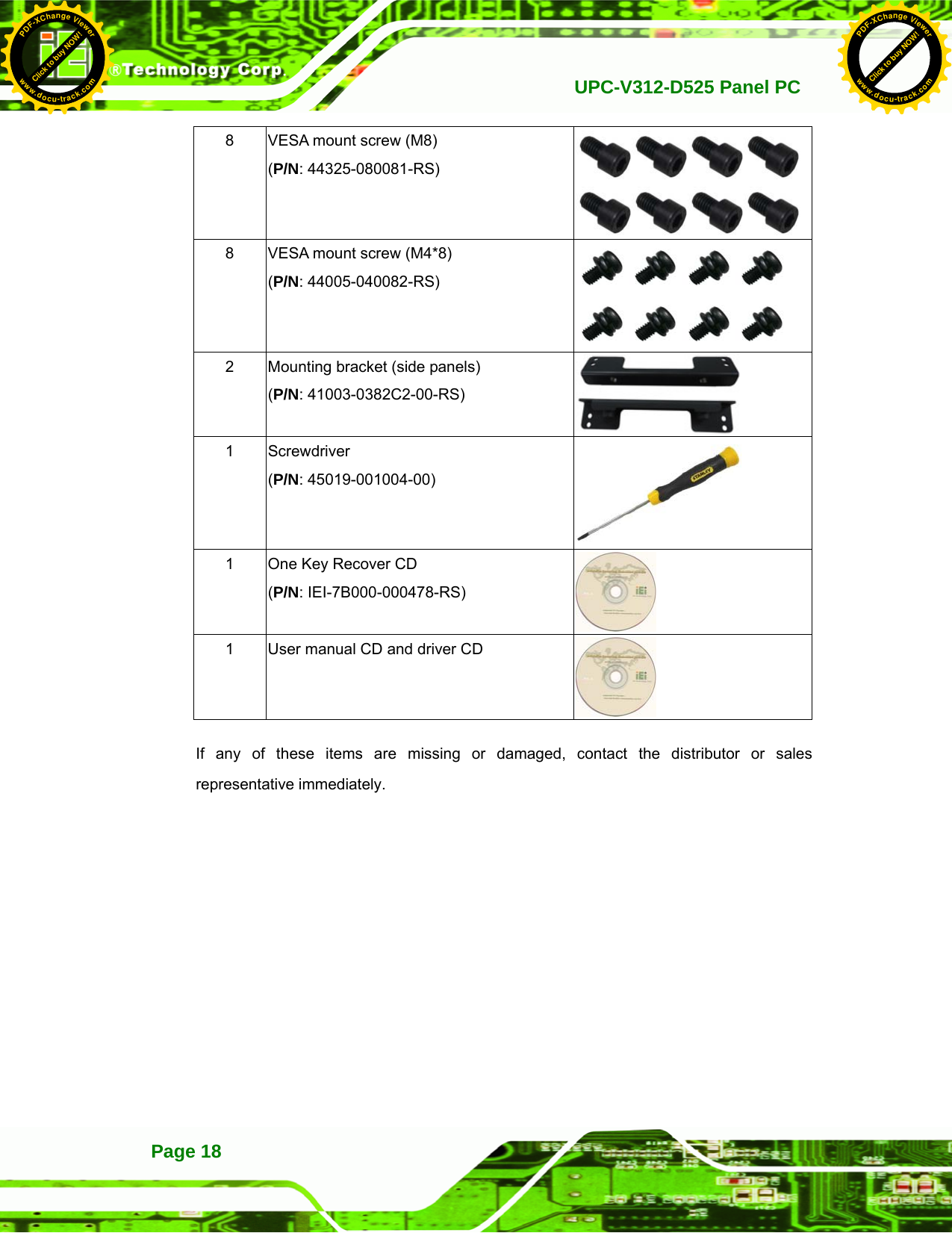
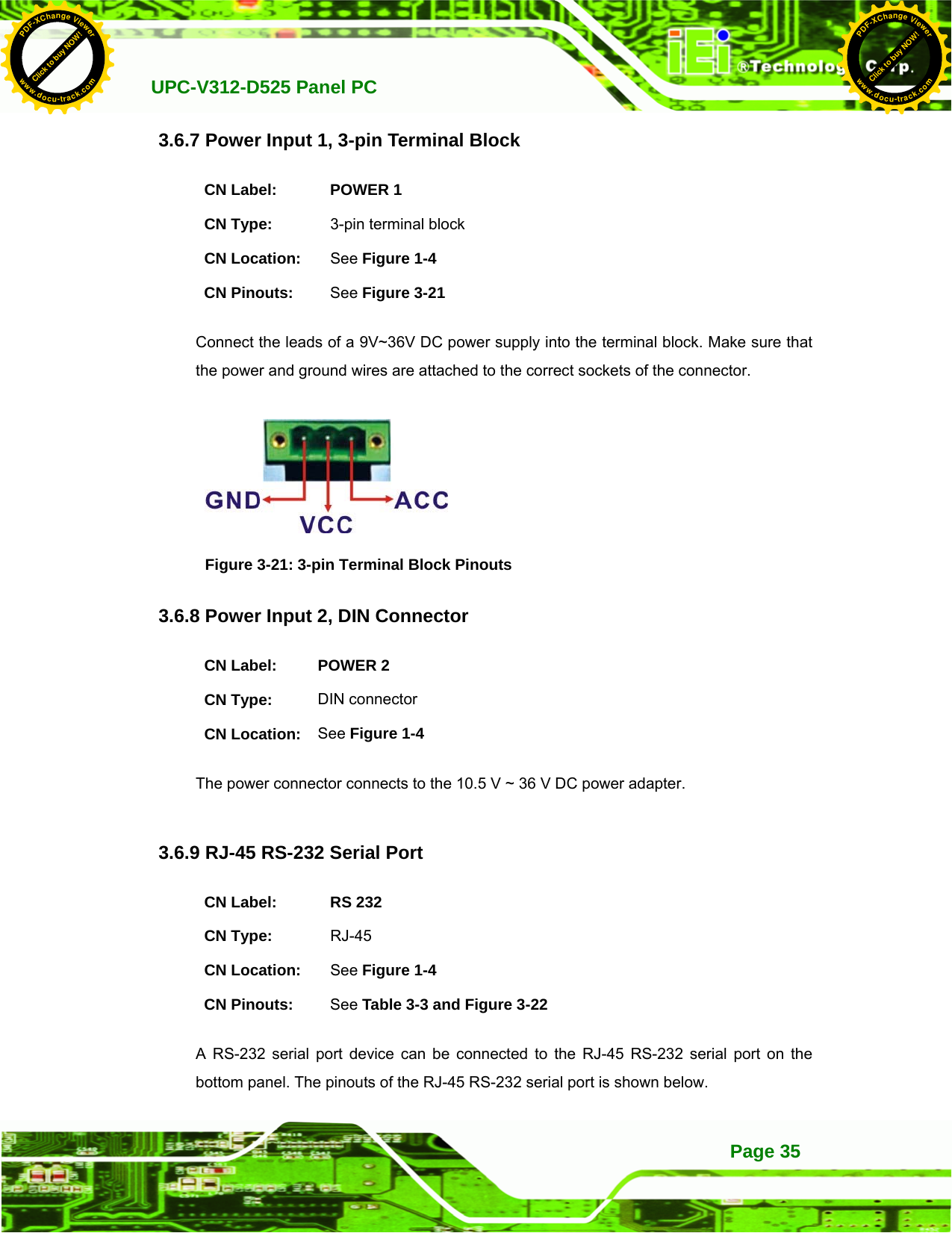
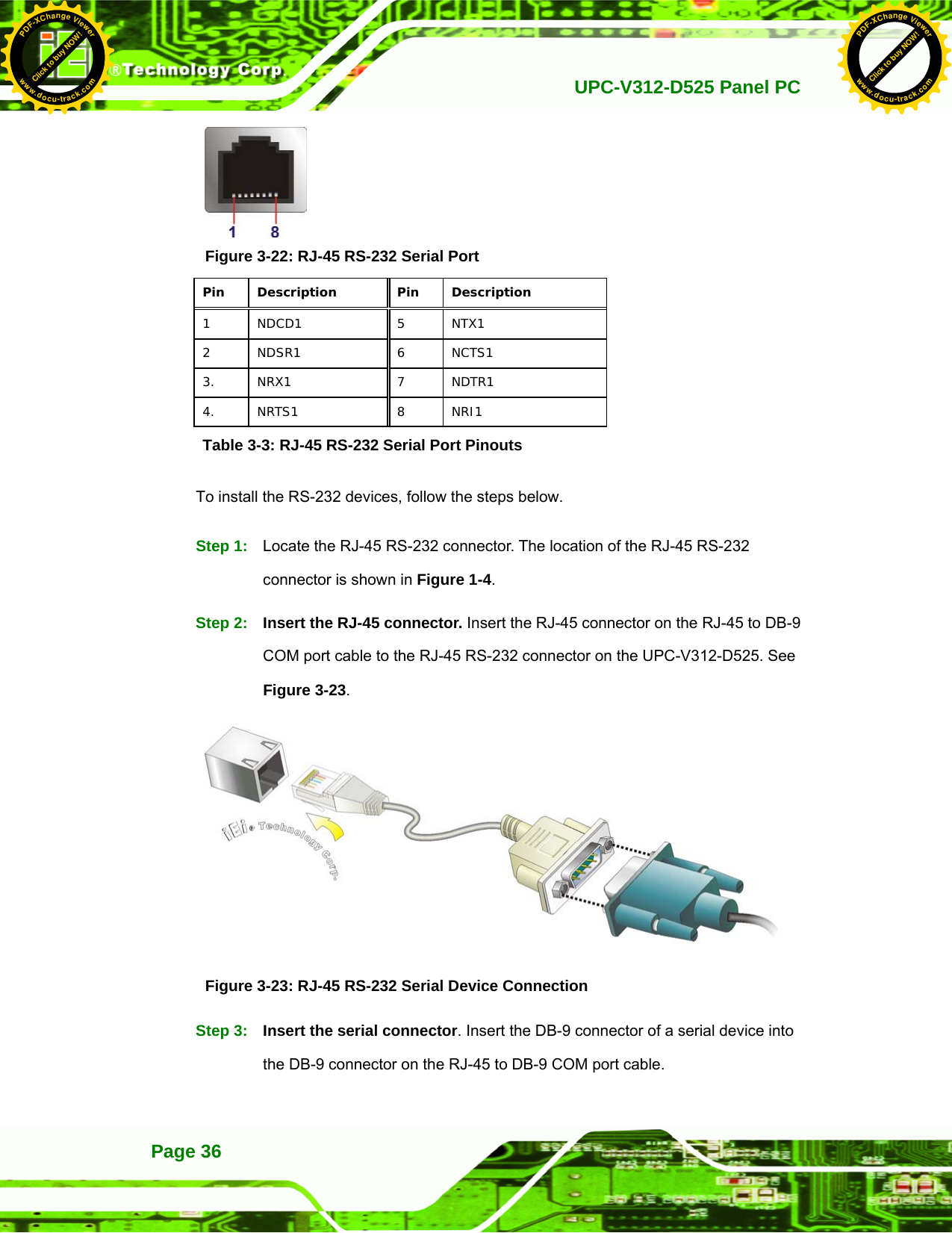
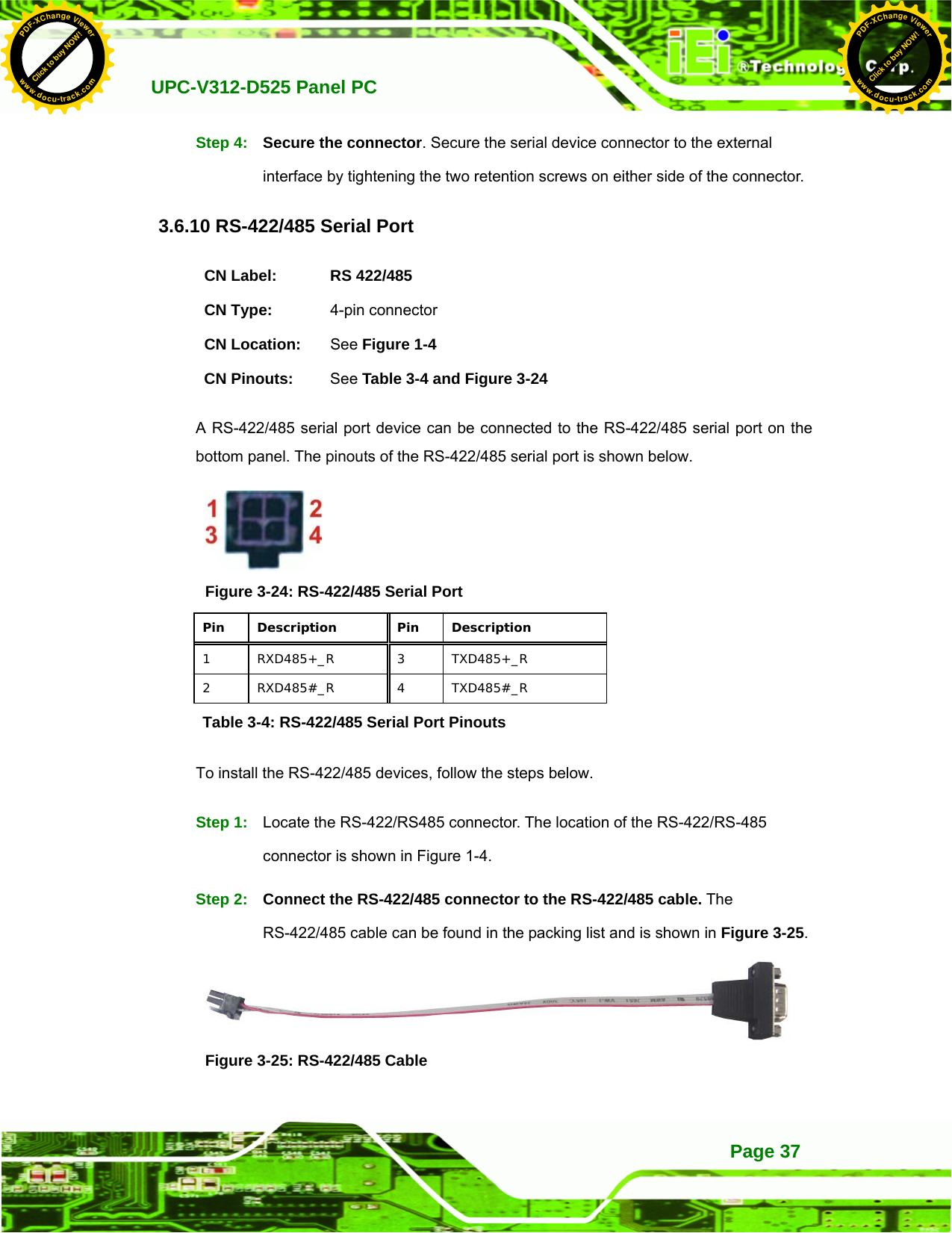
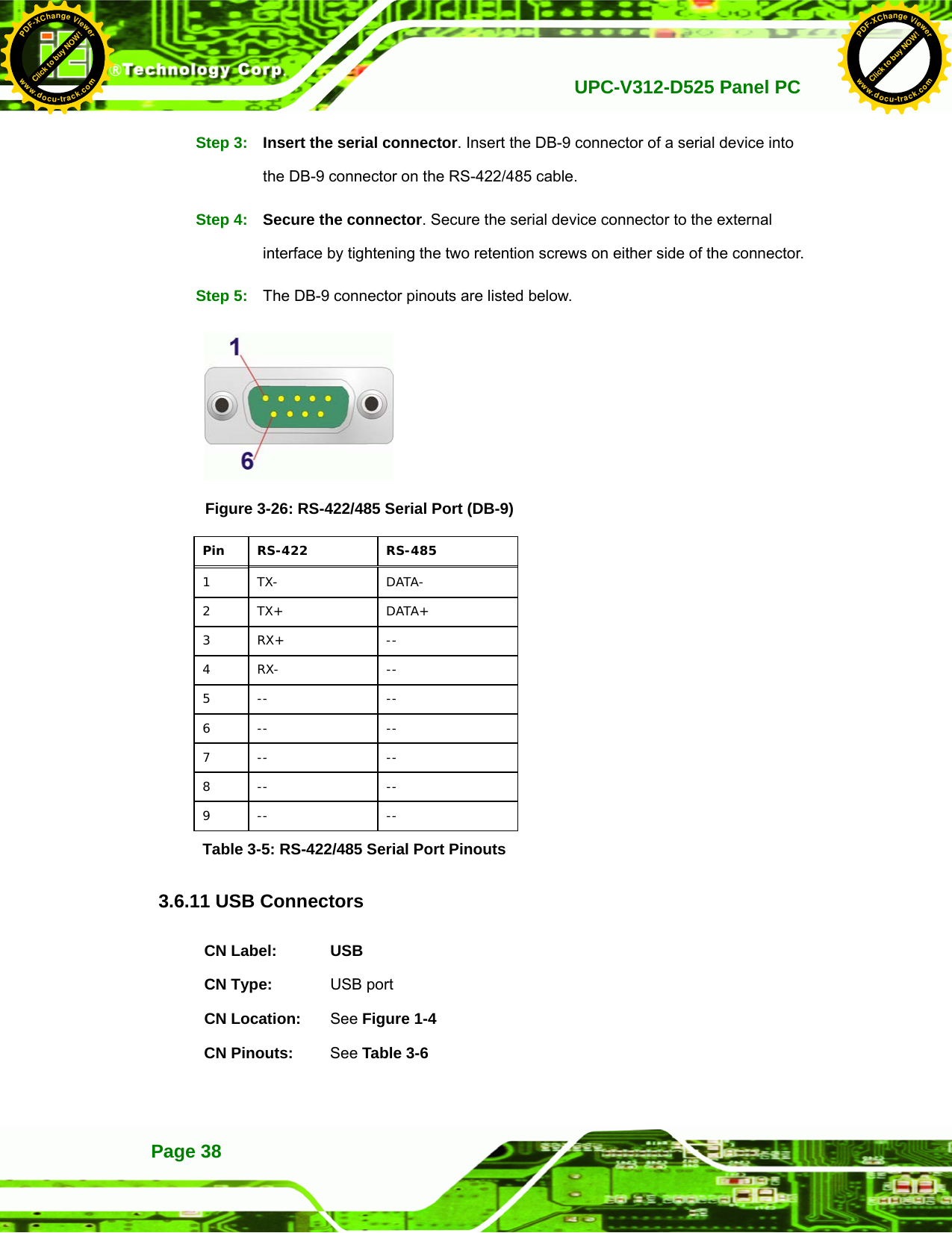
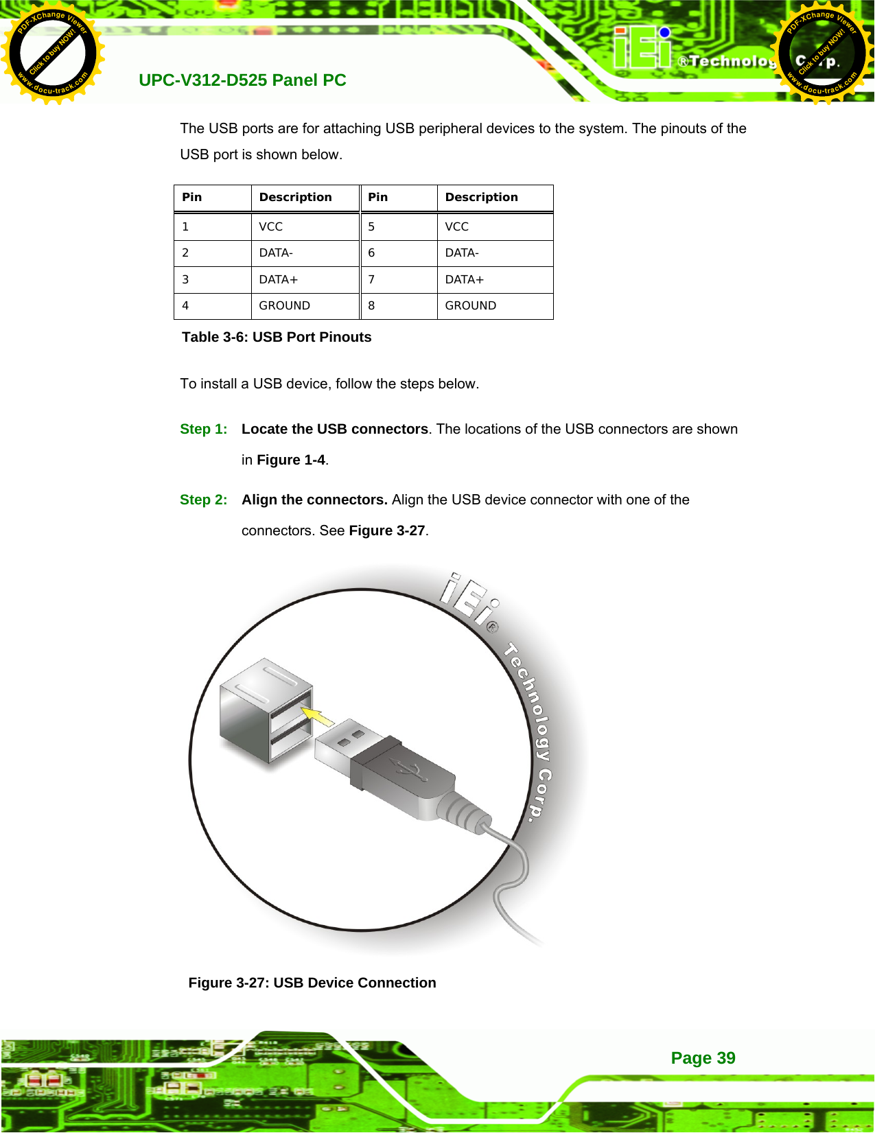
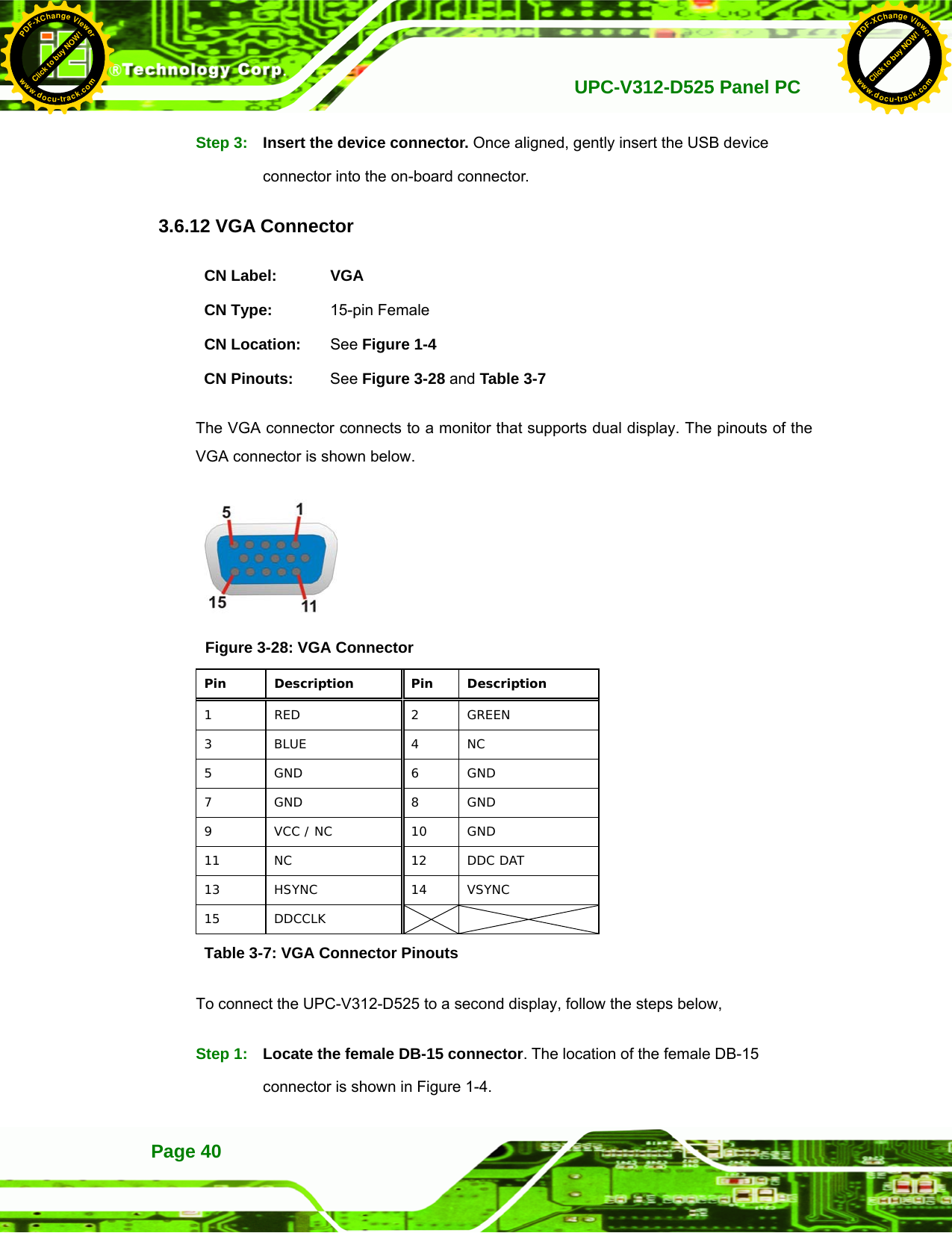
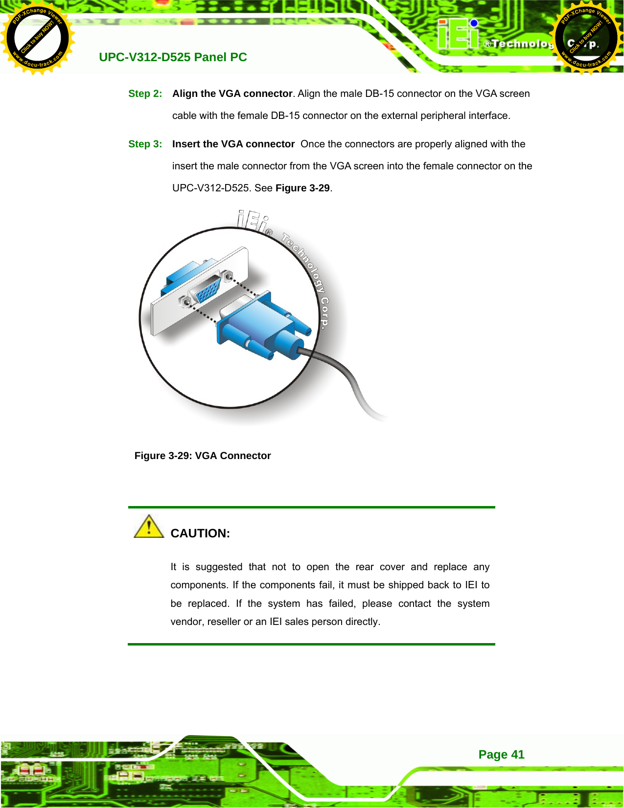
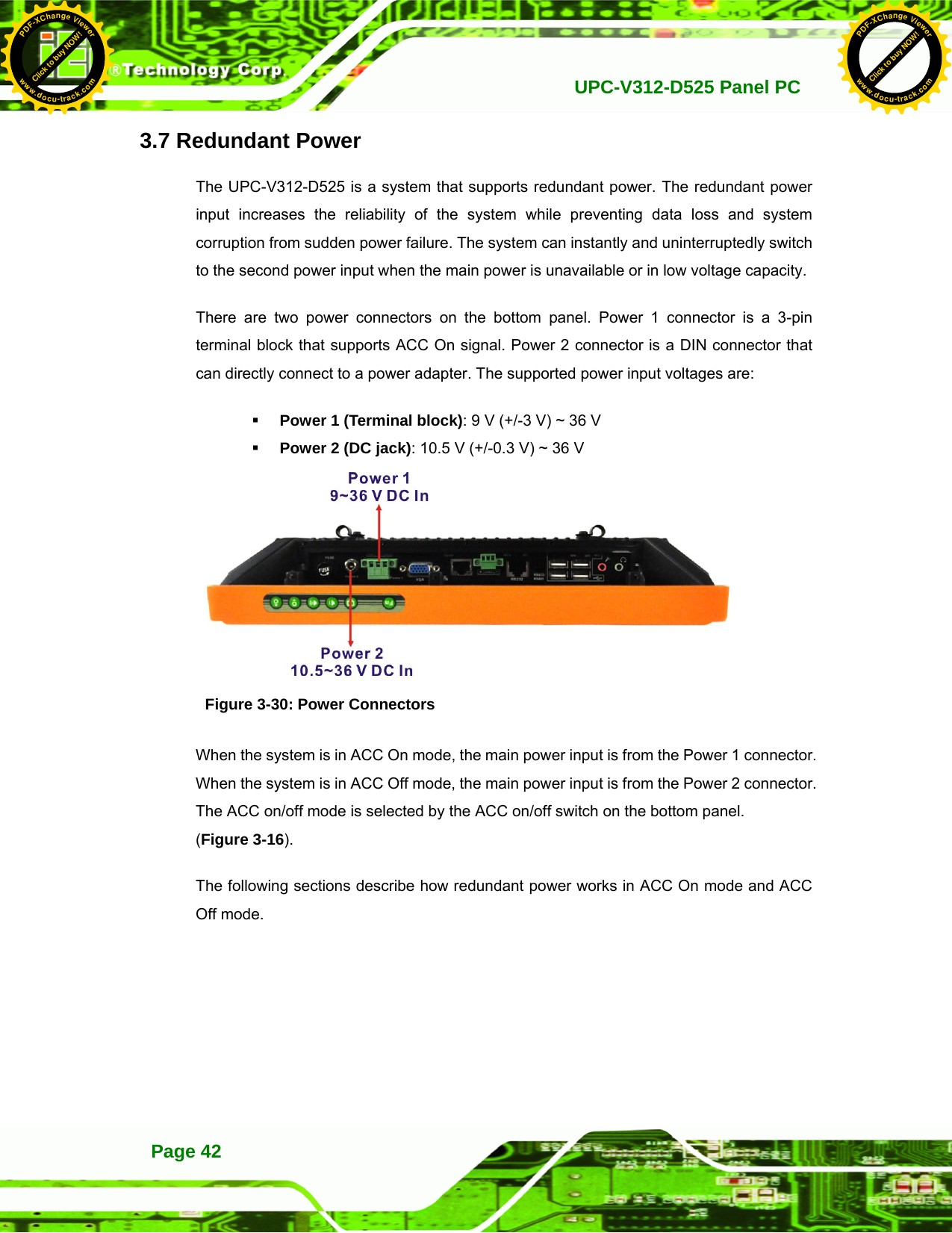
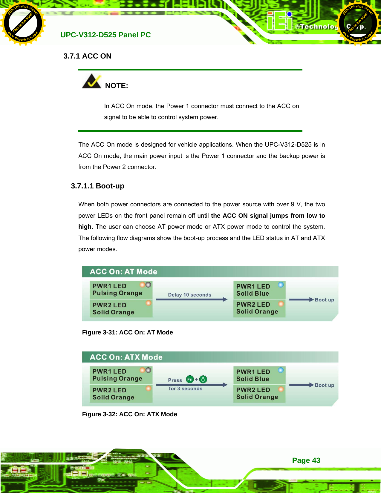
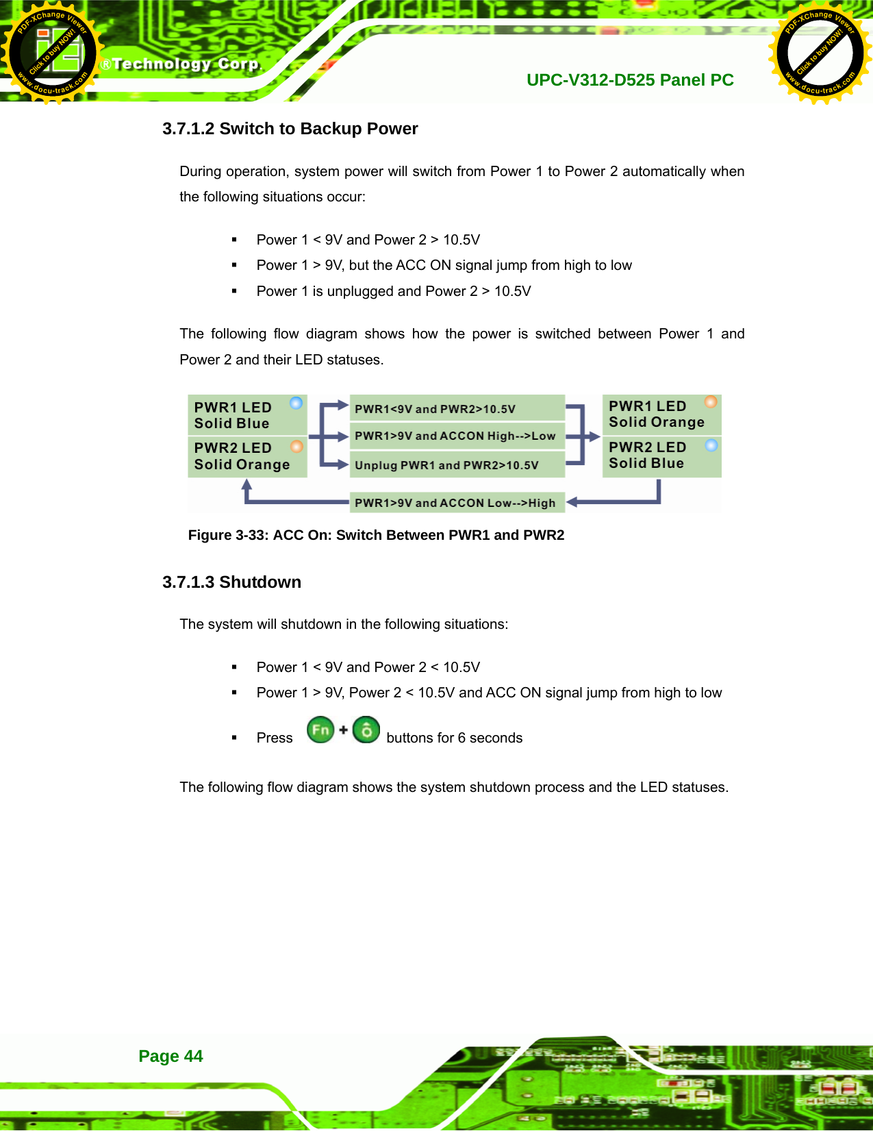
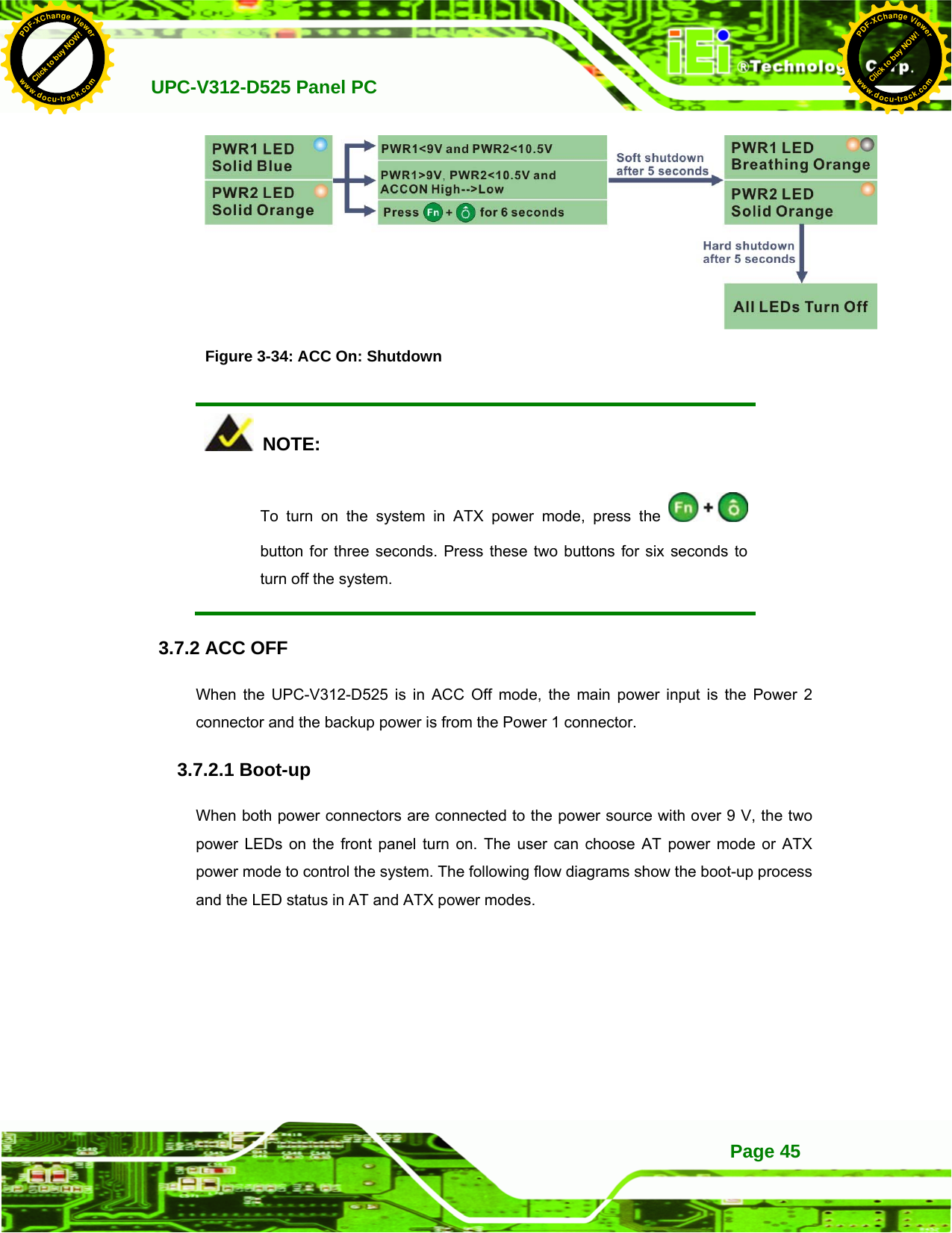
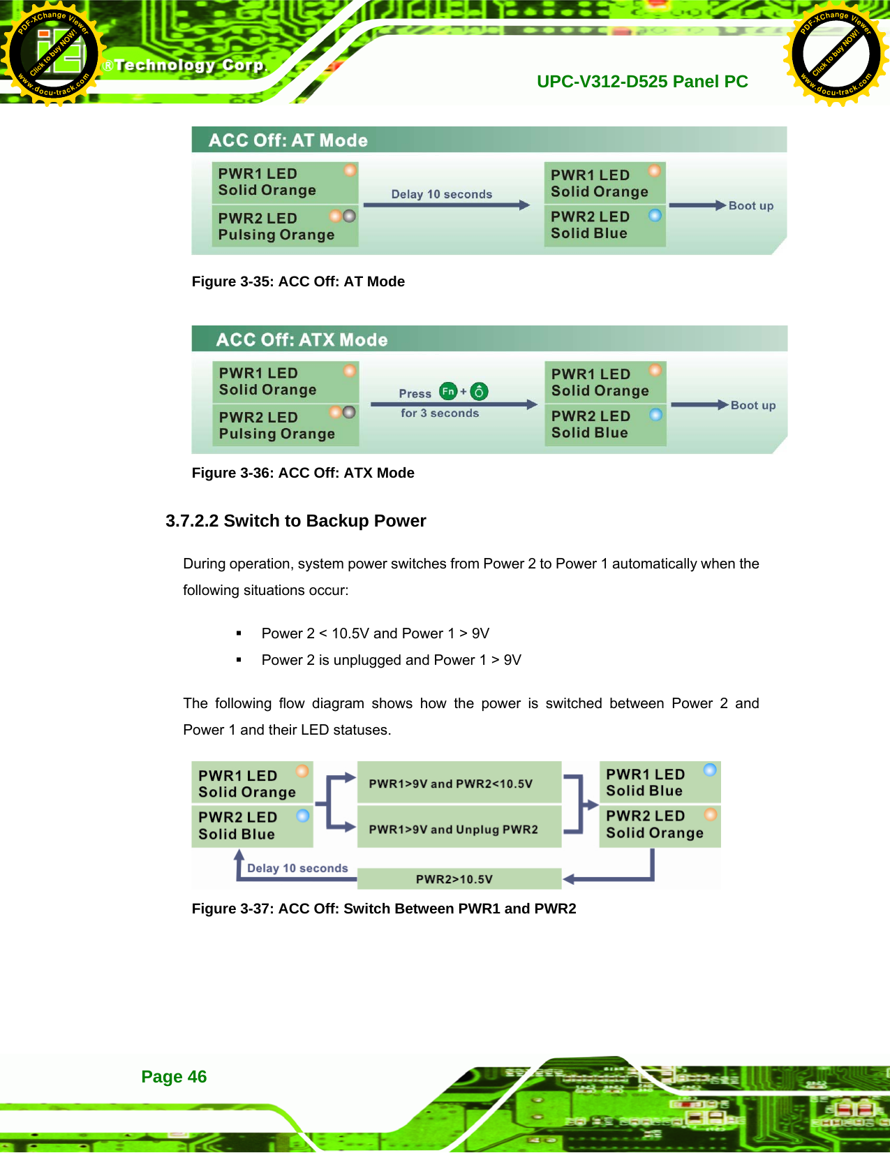
UPC-V312-D525_User Manual_Rev1_part2