IEI Integration 410UPC-V312 PANEL PC User Manual UPC V312 D525 Panel PC
IEI Integration Corp. PANEL PC UPC V312 D525 Panel PC
Contents
- 1. UPC-V312-D525_User Manual_Rev1_part3
- 2. UPC-V312-D525_User Manual_Rev1_part2
UPC-V312-D525_User Manual_Rev1_part2
UPC-V312-D525 Panel PC
Page 9
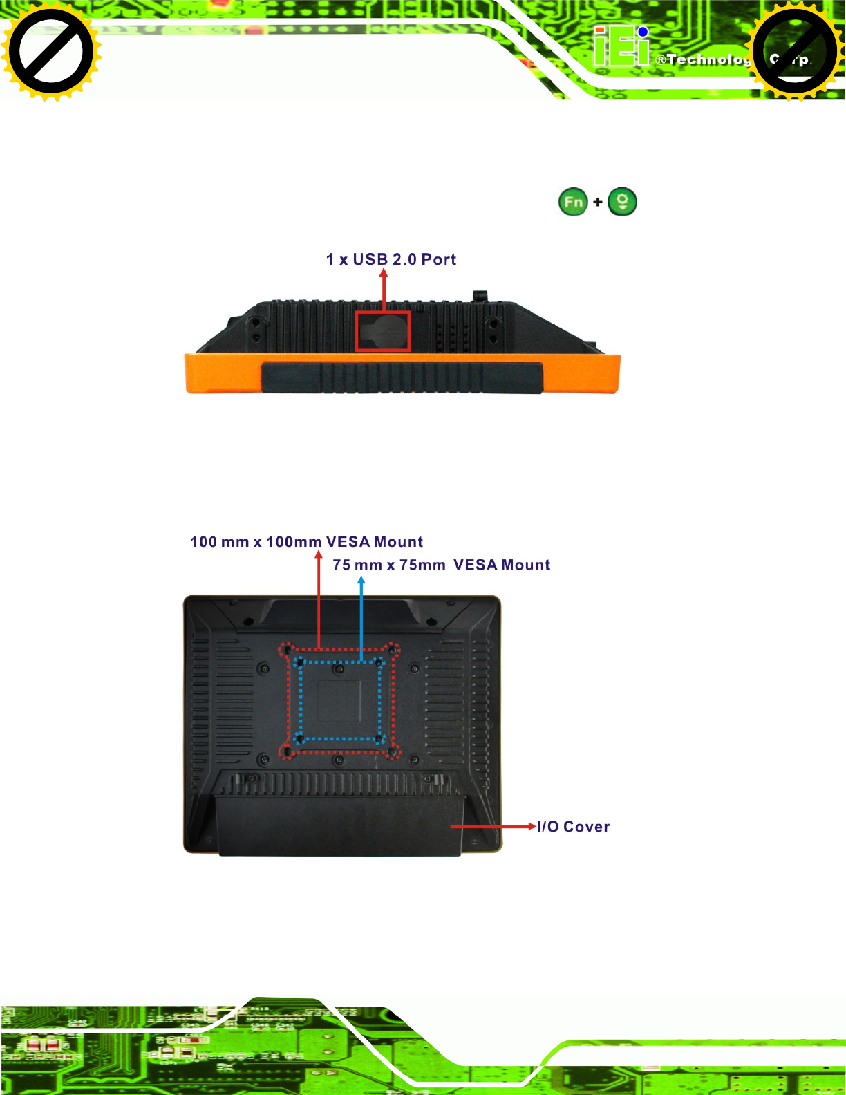
1.4.4 Right Side Panel
The right side panel of the panel PC provides access to a USB 2.0 port (55Figure 1-6).
Enable or disable this USB port by pressing the function keys: .
Figure 1-6: Left Side View
1.4.5 Rear Panel
The rear panel has retention screw holes that support a wall-mounting bracket.
Figure 1-7: Rear View
Click to buy NOW!
P
D
F
-
X
C
h
a
n
g
e
V
i
e
w
e
r
w
w
w
.
d
o
c
u
-
t
r
a
c
k
.
c
o
m
Click to buy NOW!
P
D
F
-
X
C
h
a
n
g
e
V
i
e
w
e
r
w
w
w
.
d
o
c
u
-
t
r
a
c
k
.
c
o
m
UPC-V312-D525 Panel PC
Page 10
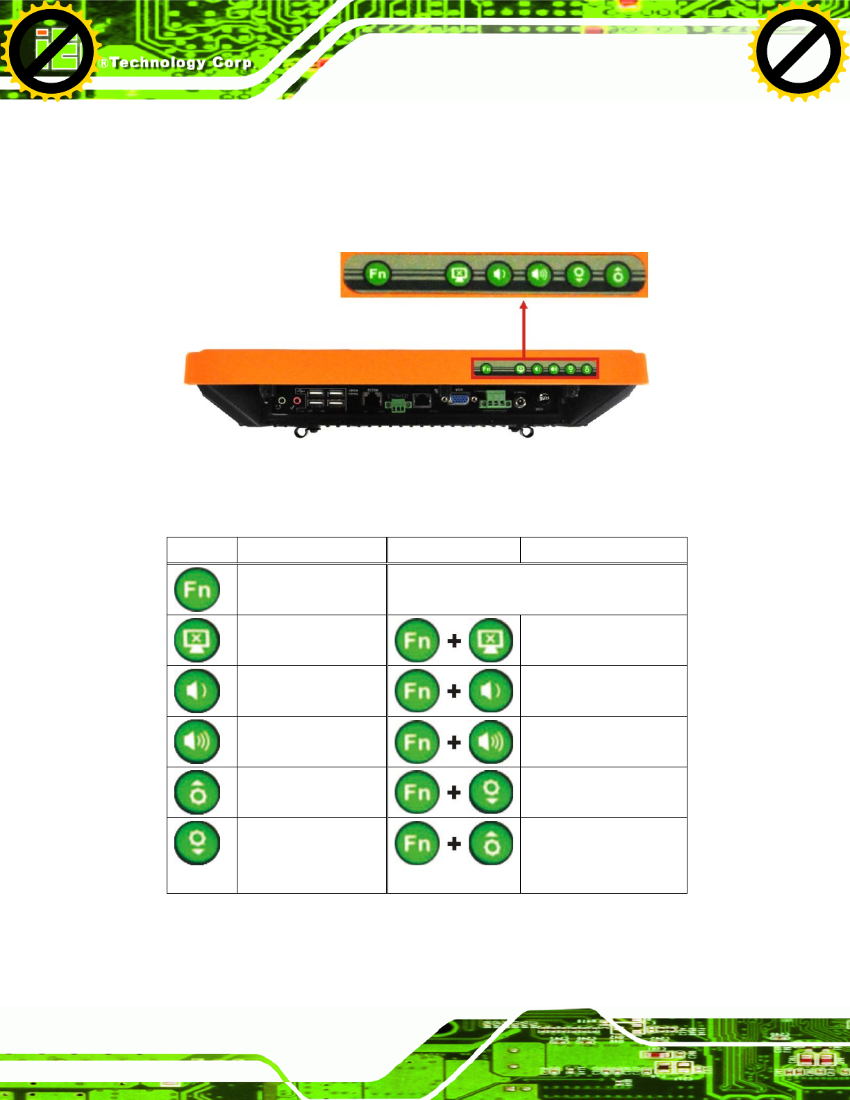
1.4.6 Frame (Function Keys)
An aluminum frame surrounds the TFT LCD screen. The aluminum frame of the
UPC-V312-D525 contains several function keys that control audio volume, LCD
brightness and some other system components.
Figure 1-8: Function Key Locations
The following table describes the function of these function keys.
Buttons Function Buttons Function
Function
LCD on/off
Enable/Disable RFID
Audio volume down
Mute audio
Audio volume up
Enable/Disable
webcam
Brightness up
Enable/Disable
right side USB port
Brightness down
Power on/off
(Turn on: press 3 seconds
Turn off: press 6 seconds)
Table 1-3: Function Keys
Click to buy NOW!
P
D
F
-
X
C
h
a
n
g
e
V
i
e
w
e
r
w
w
w
.
d
o
c
u
-
t
r
a
c
k
.
c
o
m
Click to buy NOW!
P
D
F
-
X
C
h
a
n
g
e
V
i
e
w
e
r
w
w
w
.
d
o
c
u
-
t
r
a
c
k
.
c
o
m
UPC-V312-D525 Panel PC
Page 12
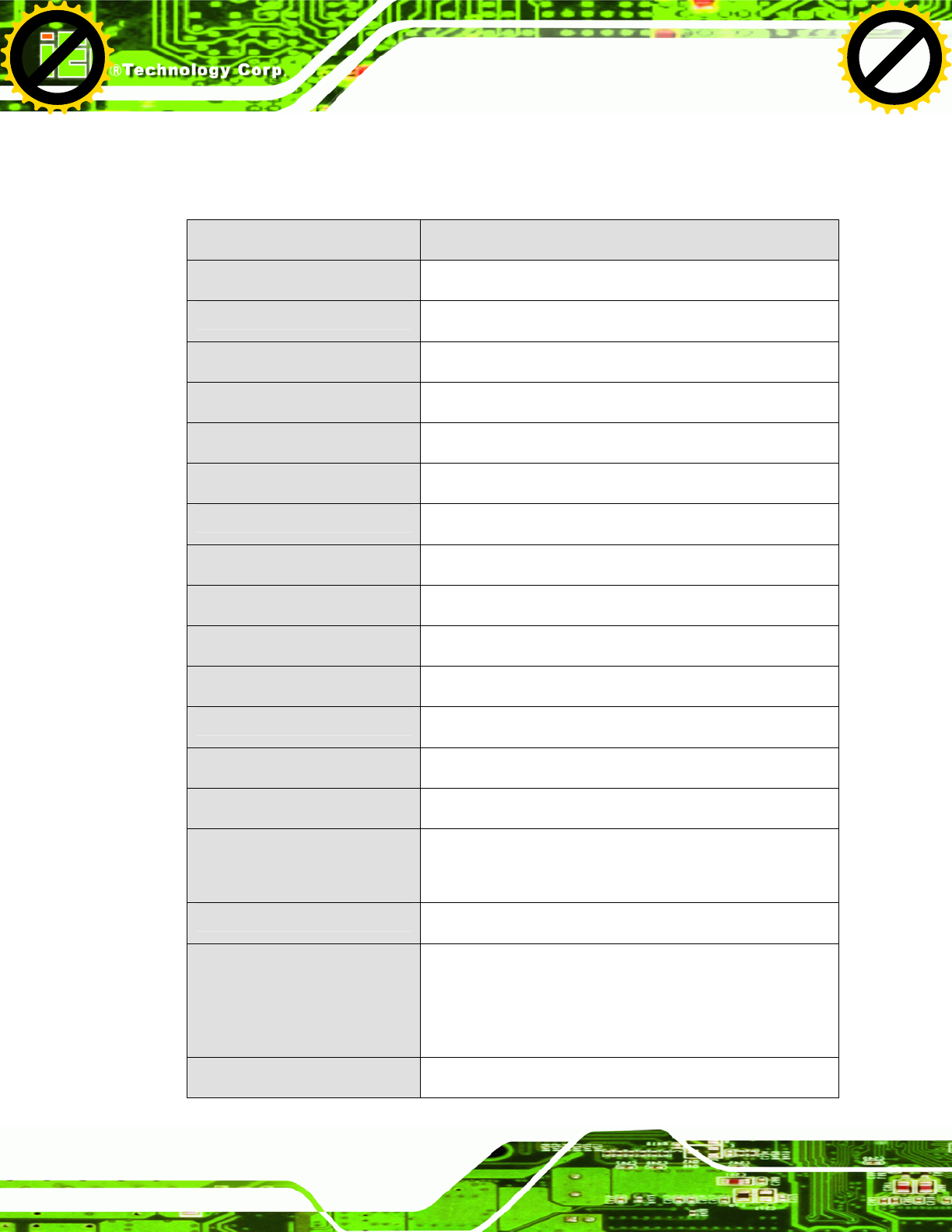
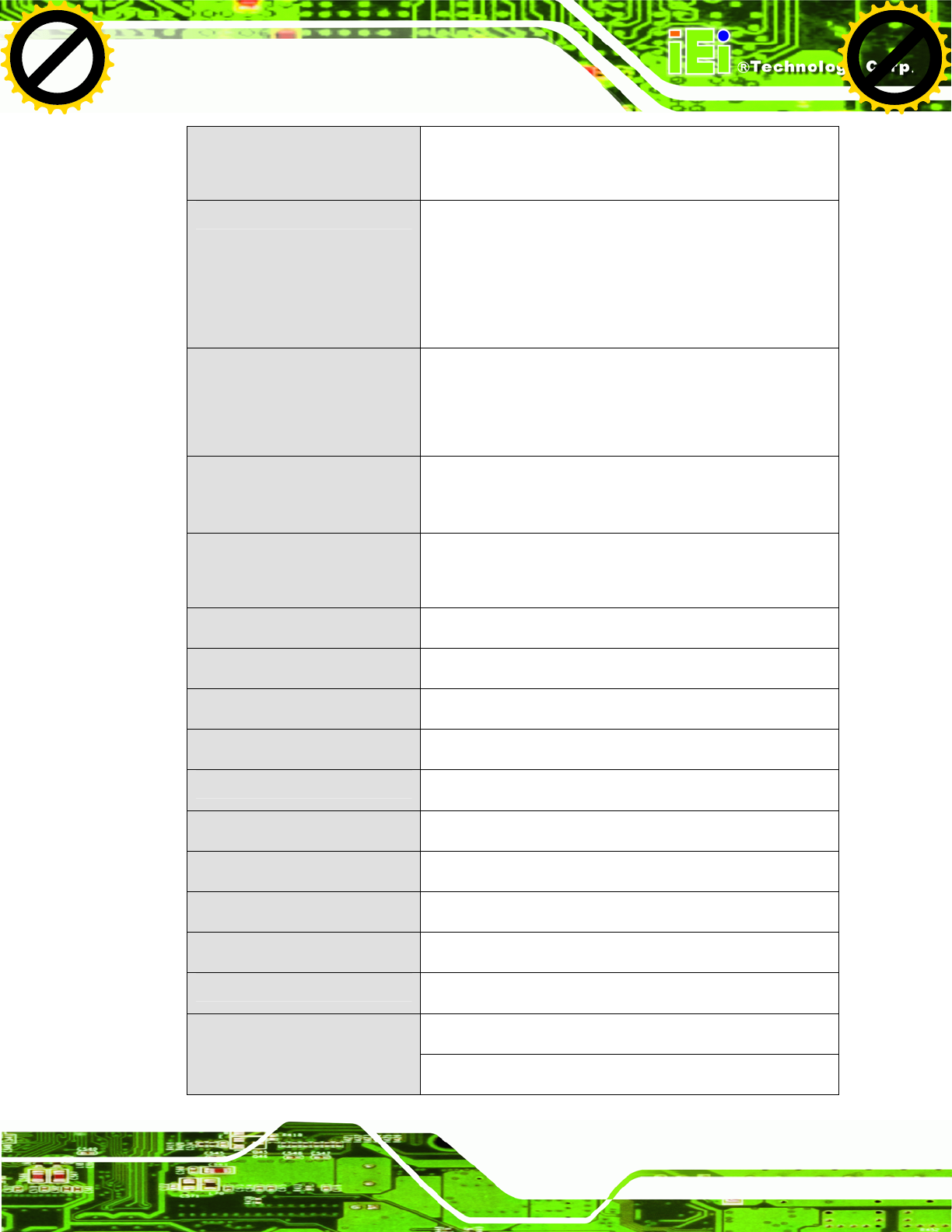
1.6 Specifications
The technical specifications for the UPC-V312-D525 system are listed in 55Table 1-4.
Specification UPC-V312-D525
LCD Size 12.1”
Max. Resolution 1024 x 768 (XGA)
Brightness
600 cd/m2
Contrast Ratio 700:1
LCD Color 16.2 M
Pixel Pitch (mm) 0.240 (H) x 0.240 (V)
Viewing Angle (H-V) 130 (H) / 150 (V)
Backlight MTBF 50,000 hours
SBC Model UPC-12AT-D525-R10
CPU 1.8 GHz Intel® Atom™ D525 dual-core processor
Chipsets ICH8M
Memory On-board 1.0 GB DDR3 SDRAM SO-DIMM
Ethernet Realtek RTL8111E PCIe GbE controller supports ASF 2.0
SSD CF Type II socket or mSATA (optional)
Watchdog Timer Software Programmable supports 1 sec. ~ 255 sec.
system reset
Camera 1.3 megapixel webcam supports AF, AE and AWB
RFID (Optional) Frequency: 125KHz or 13.56MHz
Reading distance: 5~7cm
Supports ISO 14443A Mifare or EM standard
Communication Dual-band 2.4/5GHz Wi-Fi 802.11a/b/g/n
Click to buy NOW!
P
D
F
-
X
C
h
a
n
g
e
V
i
e
w
e
r
w
w
w
.
d
o
c
u
-
t
r
a
c
k
.
c
o
m
Click to buy NOW!
P
D
F
-
X
C
h
a
n
g
e
V
i
e
w
e
r
w
w
w
.
d
o
c
u
-
t
r
a
c
k
.
c
o
m
UPC-V312-D525 Panel PC
Page 13
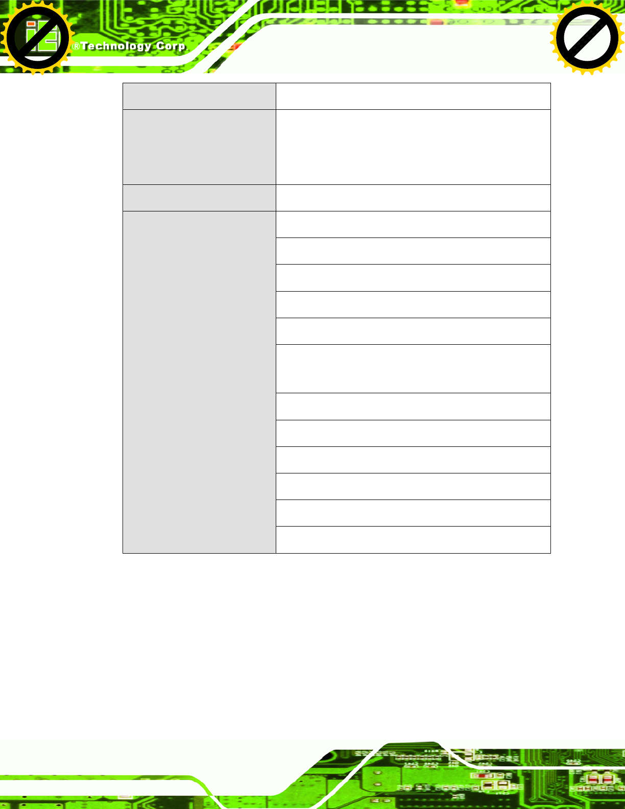
Optional GPS receiver
Optional 3.75G HSUPA USB module
Audio 2 x Audio speakers
1 x Digital microphone
1 x Line-out connector
1 x Mic-in connector
Expansion 1 x PCIe Mini interface (installed with wireless LAN 802.11
a/b/g/n module)
1 x PCIe Mini slots for mSATA (optional)
Construction Material Aluminum die-casting (front panel)
Extruded aluminum alloy (chassis)
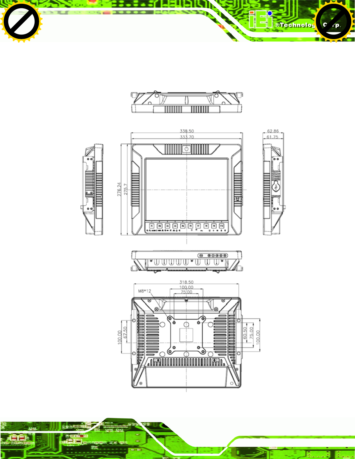
Mounting Wall, Stand, Arm (VESA 100 mm x 100 mm and 75 mm x
75 mm with M8 screws)
Front Panel Color Orange and black
Dimensions (W x H x D) (mm) 338.5 x 276.25 x 62.86
Weight (Net/Gross) 4.5kg/5.0kg
Operating Temperature -20ºC ~ 50ºC
Storage Temperature -35ºC ~ 85ºC
Relative Humidity 5%~90%, non-condensing
IP level (full system) IP 65
Touch Screen 5-wire resistive type
Vibration MIL-STD-810F 514.5C-2 (with CF card or SSD)
Shock Half-sine wave shock 3G; 11ms; 3 shocks per axis
65 W
Power Adapter
Input: 100 VAC ~ 240 VAC @ 50 Hz / 60 Hz
Click to buy NOW!
P
D
F
-
X
C
h
a
n
g
e
V
i
e
w
e
r
w
w
w
.
d
o
c
u
-
t
r
a
c
k
.
c
o
m
Click to buy NOW!
P
D
F
-
X
C
h
a
n
g
e
V
i
e
w
e
r
w
w
w
.
d
o
c
u
-
t
r
a
c
k
.
c
o
m
UPC-V312-D525 Panel PC
Page 14
Output: 19 VDC
Power Requirement Redundant dual DC input
Terminal block: 9 (+/-3) V ~ 36 V
DC jack: 10.5 (+/-0.3) V ~ 36 V
Max. Power Consumption 52 W
1 x 9~36 V DC In terminal block (Power 1)
1 x 10.5~36 V DC In connector (Power 2)
1 x CAN-bus connector
1 x RS-232 port (COM1)
1 x RS-422/485 port (COM2)
5 x USB 2.0 connectors (four on the I/O panel, one on the
side panel)
1 x GbE connector
2 x Audio jacks (Line-out, Mic-in)
1 x VGA connector
1 x AT/ATX power mode switch
1 x ACC on/off switch
I/O Ports and Switches
1 x Reset button
Table 1-4: System Specifications
Click to buy NOW!
P
D
F
-
X
C
h
a
n
g
e
V
i
e
w
e
r
w
w
w
.
d
o
c
u
-
t
r
a
c
k
.
c
o
m
Click to buy NOW!
P
D
F
-
X
C
h
a
n
g
e
V
i
e
w
e
r
w
w
w
.
d
o
c
u
-
t
r
a
c
k
.
c
o
m
UPC-V312-D525 Panel PC
Page 16
2.1 Unpacking
To unpack the panel PC, follow the steps below:
WARNING!
The front side LCD screen has a protective plastic cover stuck to the
screen. Only remove the plastic cover after the panel PC has been properly
installed. This ensures the screen is protected during the installation
process.
Step 1: Use box cutters, a knife or a sharp pair of scissors that seals the top side of the
external (second) box.
Step 2: Open the external (second) box.
Step 3: Use box cutters, a knife or a sharp pair of scissors that seals the top side of the
internal (first) box.
Step 4: Lift the monitor out of the boxes.
Step 5: Remove both polystyrene ends, one from each side.
Step 6: Pull the plastic cover off the panel PC.
Step 7: Make sure all the components listed in the packing list are present. Step 0:
Click to buy NOW!
P
D
F
-
X
C
h
a
n
g
e
V
i
e
w
e
r
w
w
w
.
d
o
c
u
-
t
r
a
c
k
.
c
o
m
Click to buy NOW!
P
D
F
-
X
C
h
a
n
g
e
V
i
e
w
e
r
w
w
w
.
d
o
c
u
-
t
r
a
c
k
.
c
o
m
UPC-V312-D525 Panel PC
Page 17
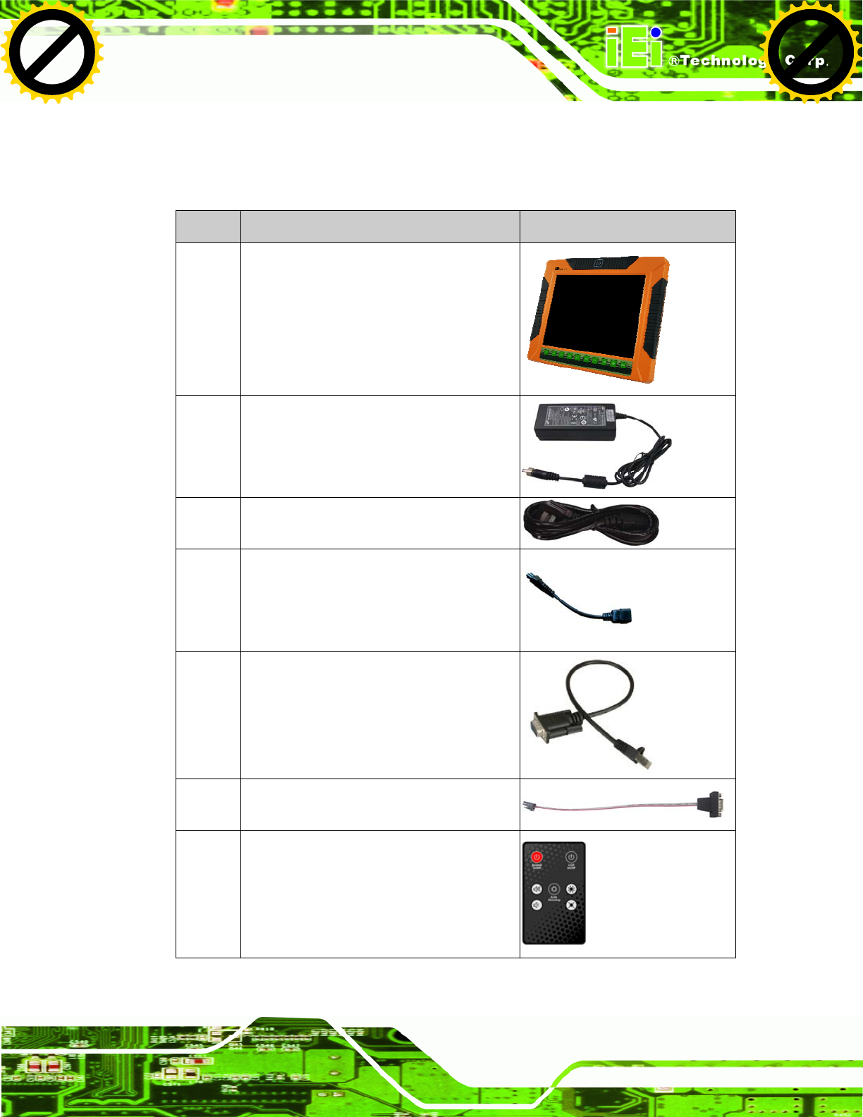
2.2 Packing List
The UPC-V312-D525 panel PC is shipped with the following components:
Quantity Item Image
1 UPC-V312-D525 panel PC
1 Power adapter
(P/N: 63040-010065-010-RS)
1 Power cord
(P/N: 32702-000401-100-RS)
1 Power transfer cord
(P/N: 32000-089400-RS)
1 RJ-45 to DB-9 COM port cable
(P/N: 32005-000200-200-RS)
1 RS-422 cable
(P/N: 32205-002400-100-RS)
1 Remote control
(P/N: 7Z000-SLPCB001-RS)
Click to buy NOW!
P
D
F
-
X
C
h
a
n
g
e
V
i
e
w
e
r
w
w
w
.
d
o
c
u
-
t
r
a
c
k
.
c
o
m
Click to buy NOW!
P
D
F
-
X
C
h
a
n
g
e
V
i
e
w
e
r
w
w
w
.
d
o
c
u
-
t
r
a
c
k
.
c
o
m
UPC-V312-D525 Panel PC
Page 18
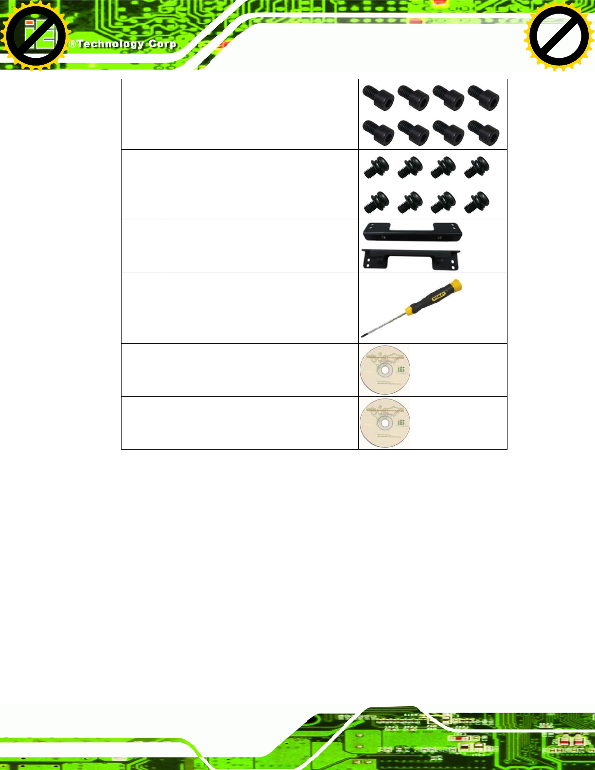
8 VESA mount screw (M8)
(P/N: 44325-080081-RS)
8 VESA mount screw (M4*8)
(P/N: 44005-040082-RS)
2 Mounting bracket (side panels)
(P/N: 41003-0382C2-00-RS)
1 Screwdriver
(P/N: 45019-001004-00)
1 One Key Recover CD
(P/N: IEI-7B000-000478-RS)
1 User manual CD and driver CD
If any of these items are missing or damaged, contact the distributor or sales
representative immediately.
Click to buy NOW!
P
D
F
-
X
C
h
a
n
g
e
V
i
e
w
e
r
w
w
w
.
d
o
c
u
-
t
r
a
c
k
.
c
o
m
Click to buy NOW!
P
D
F
-
X
C
h
a
n
g
e
V
i
e
w
e
r
w
w
w
.
d
o
c
u
-
t
r
a
c
k
.
c
o
m

UPC-V312-D525 Panel PC
Page 20
3.1 Anti-static Precautions
WARNING:
Failure to take ESD precautions during the maintenance of the EP
series may result in permanent damage to the EP series and severe
injury to the user.
Electrostatic discharge (ESD) can cause serious damage to electronic components,
including the UPC-V312-D525. Dry climates are especially susceptible to ESD. It is
therefore critical that whenever the UPC-V312-D525 is accessed internally, or any other
electrical component is handled, the following anti-static precautions are strictly adhered
to.
Wear an anti-static wristband: - Wearing a simple anti-static wristband can
help to prevent ESD from damaging the board.
Self-grounding: - Before handling the board touch any grounded conducting
material. During the time the board is handled, frequently touch any
conducting materials that are connected to the ground.
Use an anti-static pad: - When configuring the UPC-V312-D525, place it on
an antic-static pad. This reduces the possibility of ESD damaging the
UPC-V312-D525.
Only handle the edges of the PCB: - When handling the PCB, hold the PCB
by the edges.
3.2 Installation Precautions
When installing the panel PC, please follow the precautions listed below:
Power turned off: When installing the panel PC, make sure the power is off.
Failing to turn off the power may cause severe injury to the body and/or
damage to the system.
Certified Engineers: Only certified engineers should install and modify
onboard functionalities.
Anti-static Discharge: If a user open the rear panel of the panel PC, to
Click to buy NOW!
P
D
F
-
X
C
h
a
n
g
e
V
i
e
w
e
r
w
w
w
.
d
o
c
u
-
t
r
a
c
k
.
c
o
m
Click to buy NOW!
P
D
F
-
X
C
h
a
n
g
e
V
i
e
w
e
r
w
w
w
.
d
o
c
u
-
t
r
a
c
k
.
c
o
m
UPC-V312-D525 Panel PC
Page 21
configure the jumpers or plug in added peripheral devices, ground themselves
first and wear and anti-static wristband.
3.3 Preinstalled Components
The following components are all preinstalled.
Motherboard
TFT LCD screen
DDR3 memory module
Resistive type touch screen
Stereo speakers
Wireless module
Webcam
Preinstalled OEM customizations may include the following.
Different DDR3 memory module
RFID reader
GPS receiver
3.75G / HSUPA USB module
mSATA
CAUTION:
The UPC-V312-D525 is an IP 65 compliant panel PC. A user cannot
open the rear cover and install any components inside the
UPC-V312-D525. Doing so may compromise the system’s waterproof
performance. To install components in the system, please contact the
system vendor, reseller or an IEI sales person directly.
Click to buy NOW!
P
D
F
-
X
C
h
a
n
g
e
V
i
e
w
e
r
w
w
w
.
d
o
c
u
-
t
r
a
c
k
.
c
o
m
Click to buy NOW!
P
D
F
-
X
C
h
a
n
g
e
V
i
e
w
e
r
w
w
w
.
d
o
c
u
-
t
r
a
c
k
.
c
o
m
UPC-V312-D525 Panel PC
Page 22
3.4 CF Card Installation
The UPC-V312-D525 has one CF Type II slot. To install the CF card, follow the
instructions below.
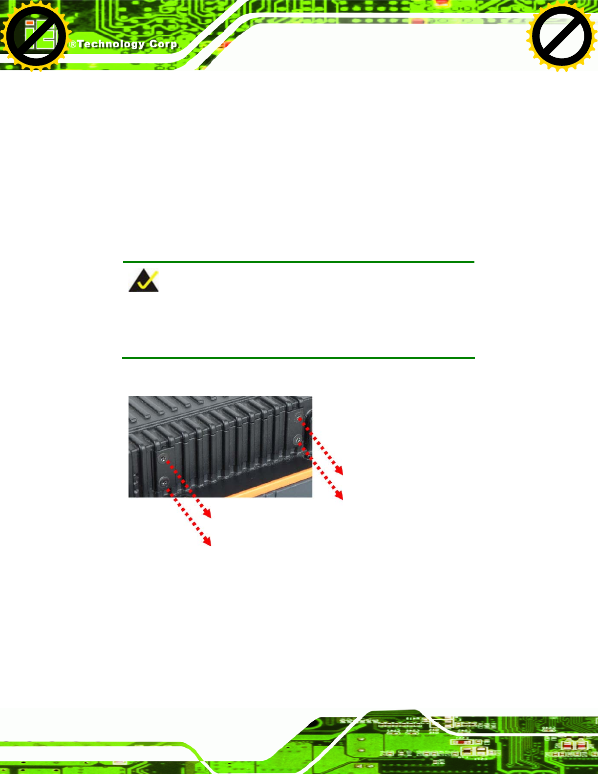
Step 1: Locate the CF card socket. The CF card socket is located on the left side panel
of the UPC-V312-D525.
Step 2: Remove the CF card slot panel by removing the four retention screws.
NOTE:
Please use the screw driver that comes with the UPC-V312-D525 to
remove the screws on the chassis.
Figure 3-1: Remove the CF Card Slot Panel
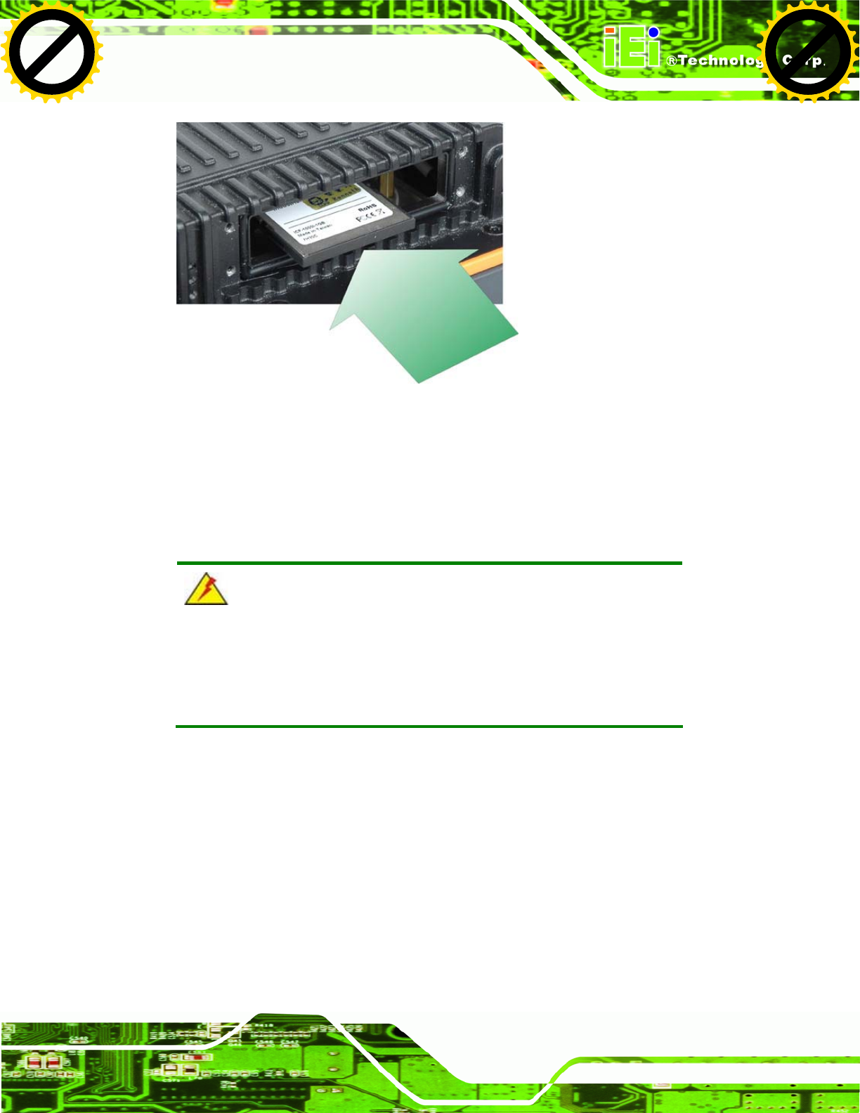
Step 3: Install the CF Card. Correctly align the CF card with the socket and insert the
CF card into the socket. See 55Figure 3-2.
Click to buy NOW!
P
D
F
-
X
C
h
a
n
g
e
V
i
e
w
e
r
w
w
w
.
d
o
c
u
-
t
r
a
c
k
.
c
o
m
Click to buy NOW!
P
D
F
-
X
C
h
a
n
g
e
V
i
e
w
e
r
w
w
w
.
d
o
c
u
-
t
r
a
c
k
.
c
o
m
UPC-V312-D525 Panel PC
Page 23
Figure 3-2: CF Card Installation
Step 4: Reinstall the CF card slot panel. Step 0:
3.5 Mounting the System
WARNING:
When mounting the panel PC onto an arm or onto the wall, it is better
to have more than one person to help with the installation to make sure
the panel PC does not fall down and get damaged.
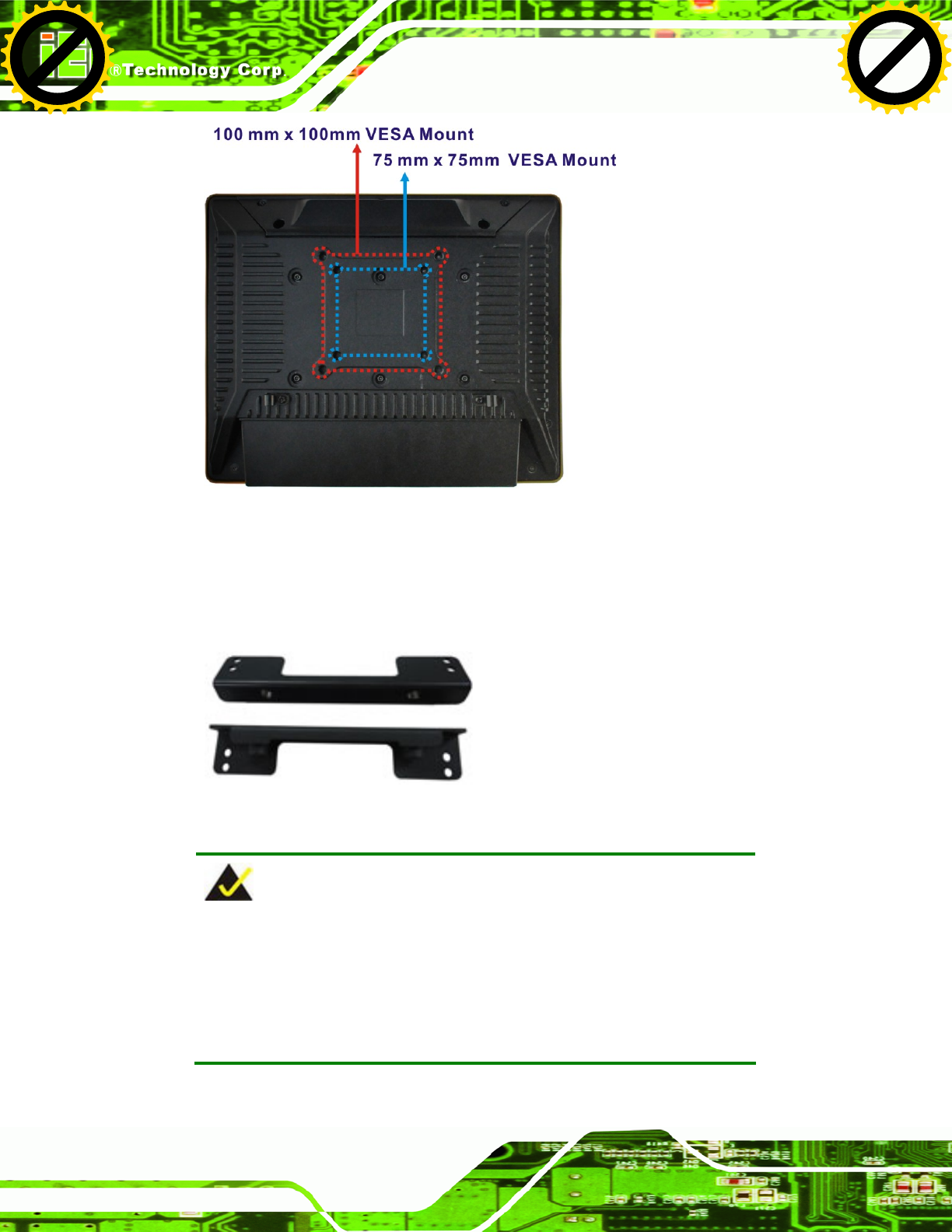
The panel PC is VESA (Video Electronics Standards Association) compliant and can be
mounted on an arm, a stand or a bracket with a 100 mm/75 mm interface pad. M8 and M4
mounting screws can both be used for VESA mount. The VESA mount retention screw
holes of the UPC-V312-D525 are shown in Figure 3-3.
Click to buy NOW!
P
D
F
-
X
C
h
a
n
g
e
V
i
e
w
e
r
w
w
w
.
d
o
c
u
-
t
r
a
c
k
.
c
o
m
Click to buy NOW!
P
D
F
-
X
C
h
a
n
g
e
V
i
e
w
e
r
w
w
w
.
d
o
c
u
-
t
r
a
c
k
.
c
o
m
UPC-V312-D525 Panel PC
Page 24
Figure 3-3: VESA Mount Retention Screw Holes
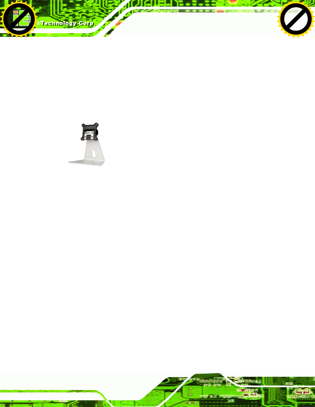
To enhance the stability, the user can use the mounting brackets, which are shipped with
the UPC-V312-D525 and can be attached on both side panels. An additional mounting
device is required for the mounting brackets.
Figure 3-4: Mounting Brackets (Side Panels)
NOTE:
When mounting the UPC-V312-D525 on a vehicle, it is recommended
to use the M8 mounting screws on the real panel. A special mounting
bracket is required for M8 mounting screw. Please contact IEI for more
information.
Click to buy NOW!
P
D
F
-
X
C
h
a
n
g
e
V
i
e
w
e
r
w
w
w
.
d
o
c
u
-
t
r
a
c
k
.
c
o
m
Click to buy NOW!
P
D
F
-
X
C
h
a
n
g
e
V
i
e
w
e
r
w
w
w
.
d
o
c
u
-
t
r
a
c
k
.
c
o
m
UPC-V312-D525 Panel PC
Page 25
The following installation options are available:
Arm mounting
Stand mounting
Wall mounting
The mounting methods are described below.
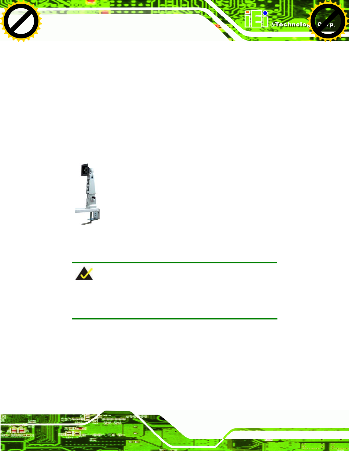
3.5.1 Arm Mounting
The UPC-V312-D525 can be installed on any arm that supports the standard VESA
mounting interface. An example arm is shown below.
Figure 3-5: VESA Compliant Arm
To install the UPC-V312-D525 on the arm, follow the directions below.
NOTE:
Make sure the arm supports standard VESA mounting. The
UPC-V312-D525 uses a VESA mounting to attach to the arm.
Step 1: The arm is purchased separately. Follow the instructions in the arm's user
manual to securely attach the arm to the wall.
Step 2: Once the mounting arm has been firmly attached to the surface, lift the panel PC
onto the interface pad of the mounting arm.
Step 3: Align the retention screw holes on the mounting arm interface with those in the
panel PC. The arm mount retention screw holes are shown in Figure 3-3.
Click to buy NOW!
P
D
F
-
X
C
h
a
n
g
e
V
i
e
w
e
r
w
w
w
.
d
o
c
u
-
t
r
a
c
k
.
c
o
m
Click to buy NOW!
P
D
F
-
X
C
h
a
n
g
e
V
i
e
w
e
r
w
w
w
.
d
o
c
u
-
t
r
a
c
k
.
c
o
m
UPC-V312-D525 Panel PC
Page 26
Step 4: Secure the flat panel PC to the interface pad by inserting four retention screws
through the bottom of the mounting arm interface pad and into the flat panel PC.
Step 0:
3.5.2 Stand Mounting
The UPC-V312-D525 can be installed on any stand that supports the standard VESA
mounting interface. An example stand is shown below.
Figure 3-6: VESA Compliant Stand
To install the UPC-V312-D525 on the stand, follow the directions below.
Step 1: Locate the screw holes on the rear of the UPC-V312-D525. This is where the
stand bracket will be attached. The stand mount retention screw holes are
shown in Figure 3-3.
Step 2: Align the bracket with the screw holes.
Step 3: Insert the retention screws into the screw holes to secure the bracket to the
UPC-V312-D525. Step 0:
3.5.3 Wall Mounting
To mount the panel PC onto the wall, please follow the steps below.
Step 1: Select the location on the wall for the wall-mounting bracket.
Step 2: Carefully mark the locations of the four brackets screw holes on the wall.
Step 3: Drill four pilot holes at the marked locations on the wall for the bracket retention
screws.
Click to buy NOW!
P
D
F
-
X
C
h
a
n
g
e
V
i
e
w
e
r
w
w
w
.
d
o
c
u
-
t
r
a
c
k
.
c
o
m
Click to buy NOW!
P
D
F
-
X
C
h
a
n
g
e
V
i
e
w
e
r
w
w
w
.
d
o
c
u
-
t
r
a
c
k
.
c
o
m
UPC-V312-D525 Panel PC
Page 27
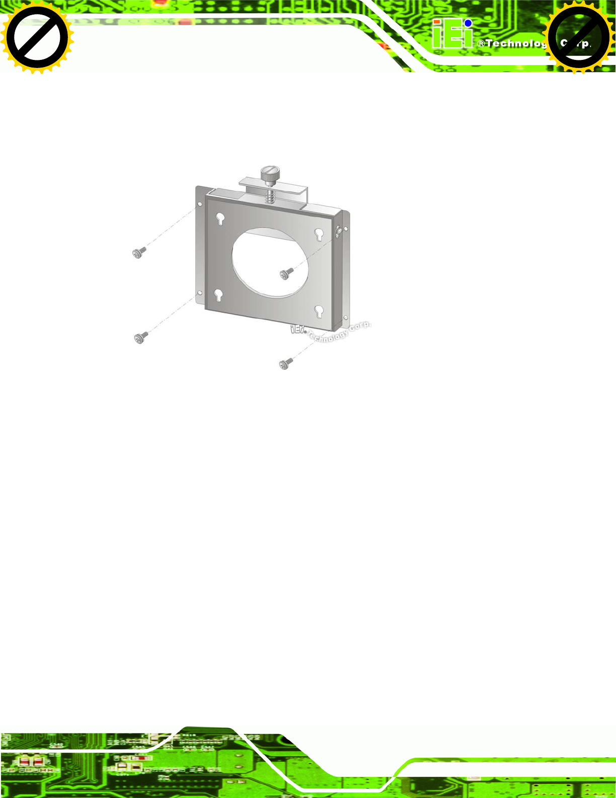
Step 4: Align the wall-mounting bracket screw holes with the pilot holes.
Step 5: Secure the mounting-bracket to the wall by inserting the retention screws into
the four pilot holes and tightening them (Figure 3-7).
Figure 3-7: Wall-mounting Bracket
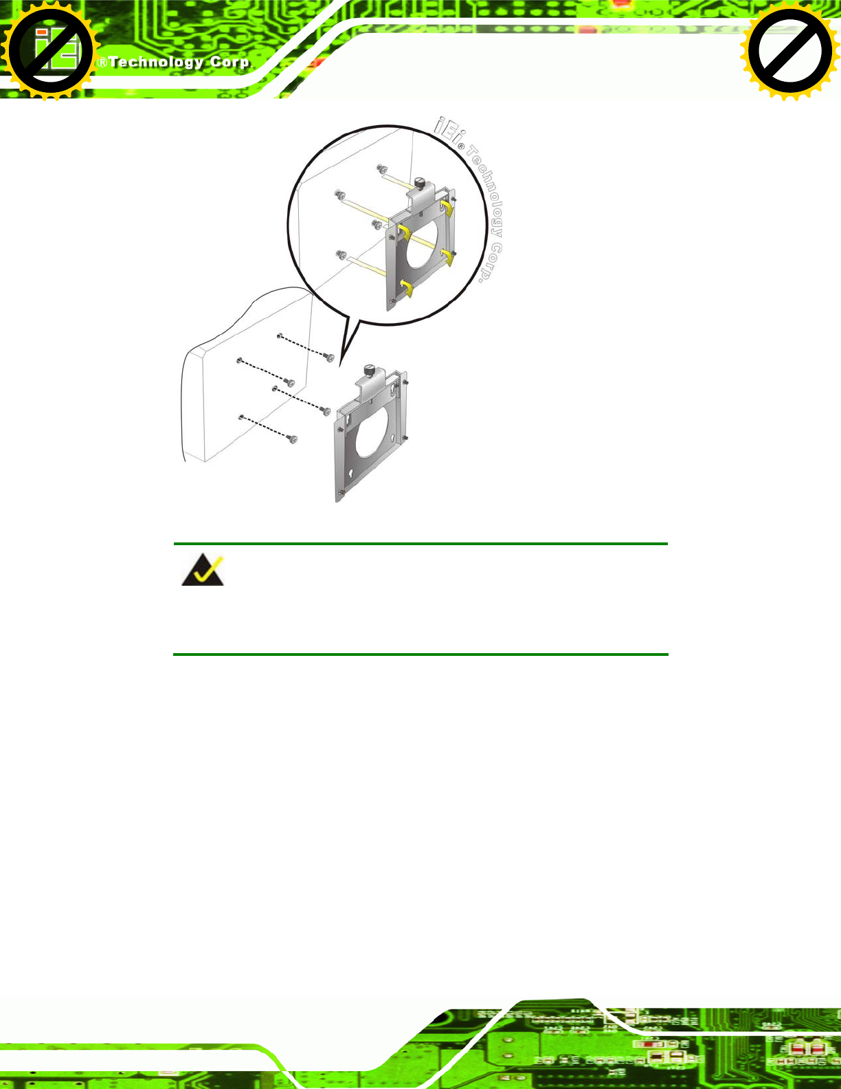
Step 6: Insert the four monitor mounting screws provided in the wall mounting kit into the
four screw holes on the real panel of the flat panel PC and tighten until the screw
shank is secured against the rear panel (Figure 3-8).
Step 7: Align the mounting screws on the monitor rear panel with the mounting holes on
the bracket.
Step 8: Carefully insert the screws through the holes and gently pull the monitor
downwards until the monitor rests securely in the slotted holes (Figure 3-8).
Ensure that all four of the mounting screws fit snuggly into their respective
slotted holes.
Click to buy NOW!
P
D
F
-
X
C
h
a
n
g
e
V
i
e
w
e
r
w
w
w
.
d
o
c
u
-
t
r
a
c
k
.
c
o
m
Click to buy NOW!
P
D
F
-
X
C
h
a
n
g
e
V
i
e
w
e
r
w
w
w
.
d
o
c
u
-
t
r
a
c
k
.
c
o
m
UPC-V312-D525 Panel PC
Page 28
Figure 3-8: Chassis Support Screws
NOTE:
In the diagram below the bracket is already installed on the wall.
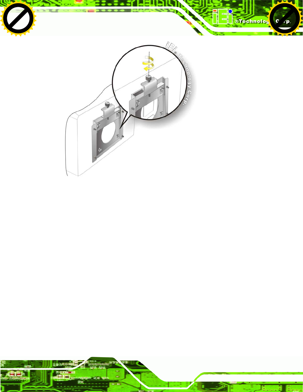
Step 9: Secure the panel PC by fastening the retention screw of the wall-mounting
bracket. (Figure 3-9).
Click to buy NOW!
P
D
F
-
X
C
h
a
n
g
e
V
i
e
w
e
r
w
w
w
.
d
o
c
u
-
t
r
a
c
k
.
c
o
m
Click to buy NOW!
P
D
F
-
X
C
h
a
n
g
e
V
i
e
w
e
r
w
w
w
.
d
o
c
u
-
t
r
a
c
k
.
c
o
m
UPC-V312-D525 Panel PC
Page 29
Figure 3-9: Secure the Panel PC
3.6 Bottom Panel Connectors
The bottom panel of the UPC-V312-D525 contains I/O connectors, switches and a reset
button. These connectors are protected by an I/O cover. Detailed descriptions of the
connectors and cabling can be found in the subsections below.
3.6.1 External Peripheral Device Connection
To install external peripheral devices to the UPC-V312-D525, please follow the steps
below.
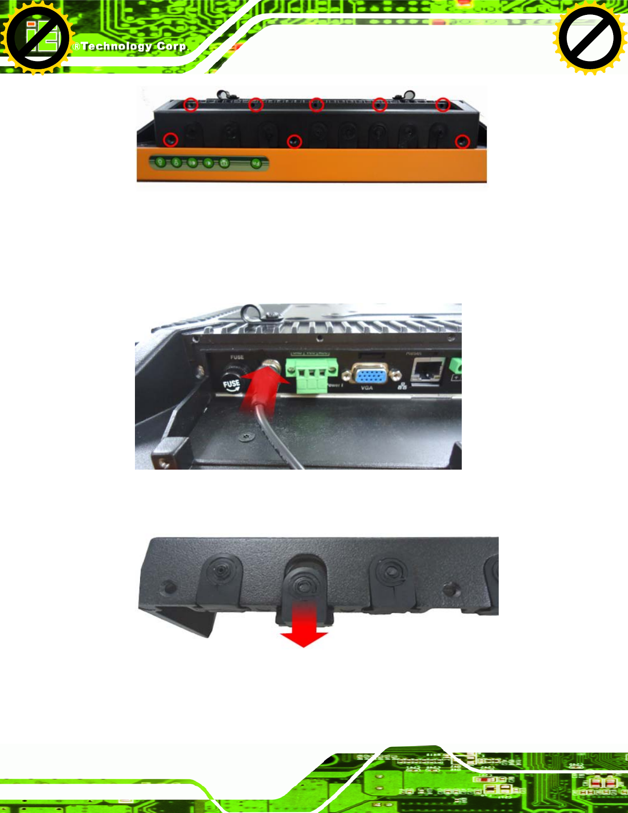
Step 1: Remove the I/O cover by removing the eight retention screws as shown in
Figure 3-10.
Click to buy NOW!
P
D
F
-
X
C
h
a
n
g
e
V
i
e
w
e
r
w
w
w
.
d
o
c
u
-
t
r
a
c
k
.
c
o
m
Click to buy NOW!
P
D
F
-
X
C
h
a
n
g
e
V
i
e
w
e
r
w
w
w
.
d
o
c
u
-
t
r
a
c
k
.
c
o
m
UPC-V312-D525 Panel PC
Page 30
Figure 3-10: I/O Cover Retention Screws
Step 2: Connect the cable from the external peripheral device to the corresponding
connector of the UPC-V312-D525 (Figure 3-11).
Figure 3-11: External Peripheral Device Connection
Step 3: Take out a rubber gasket from the I/O cover (Figure 3-12).
Figure 3-12: Rubber Gasket Removal
Click to buy NOW!
P
D
F
-
X
C
h
a
n
g
e
V
i
e
w
e
r
w
w
w
.
d
o
c
u
-
t
r
a
c
k
.
c
o
m
Click to buy NOW!
P
D
F
-
X
C
h
a
n
g
e
V
i
e
w
e
r
w
w
w
.
d
o
c
u
-
t
r
a
c
k
.
c
o
m
UPC-V312-D525 Panel PC
Page 31
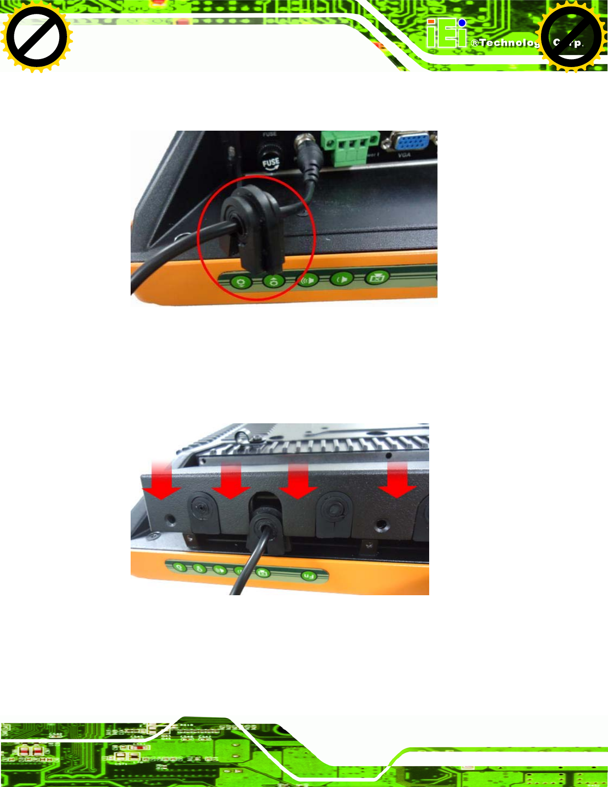
Step 4: Remove some rubber rings from the gasket to make the gasket fit perfectly to
the size of the cable (Figure 3-13).
Figure 3-13: Rubber Gasket and Cable
Step 5: Repeat steps to other connected cables.
Step 6: Install the I/O cover and make sure each rubber gasket snaps into place tightly.
Figure 3-14: Reinstall the I/O Cover
Step 7: Secure the I/O cover by the previously removed retention screws.
Click to buy NOW!
P
D
F
-
X
C
h
a
n
g
e
V
i
e
w
e
r
w
w
w
.
d
o
c
u
-
t
r
a
c
k
.
c
o
m
Click to buy NOW!
P
D
F
-
X
C
h
a
n
g
e
V
i
e
w
e
r
w
w
w
.
d
o
c
u
-
t
r
a
c
k
.
c
o
m
UPC-V312-D525 Panel PC
Page 32
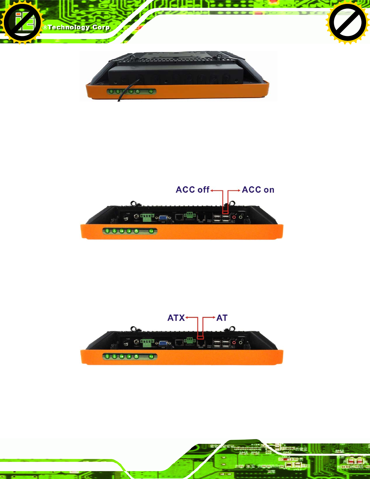
Figure 3-15: External Peripheral Device Connection Complete
3.6.2 ACC Mode Selection
The ACC mode can be turned on or off. The setting is made through the ACC mode switch
on the bottom panel as shown below.
Figure 3-16: ACC Mode Switch
3.6.3 AT/ATX Power Mode Selection
The UPC-V312-D525 supports both AT and ATX power modes. The setting can be made
through the AT/ATX power mode switch on the bottom panel as shown below.
Figure 3-17: AT/ATX Power Mode Switch
Click to buy NOW!
P
D
F
-
X
C
h
a
n
g
e
V
i
e
w
e
r
w
w
w
.
d
o
c
u
-
t
r
a
c
k
.
c
o
m
Click to buy NOW!
P
D
F
-
X
C
h
a
n
g
e
V
i
e
w
e
r
w
w
w
.
d
o
c
u
-
t
r
a
c
k
.
c
o
m
UPC-V312-D525 Panel PC
Page 33
3.6.4 Audio Connectors
The audio jacks connect to external audio devices.
Microphone (Pink): Connects a microphone.
Line Out port (Green): Connects to a headphone or a speaker. With
multi-channel configurations, this port can also connect to front speakers.
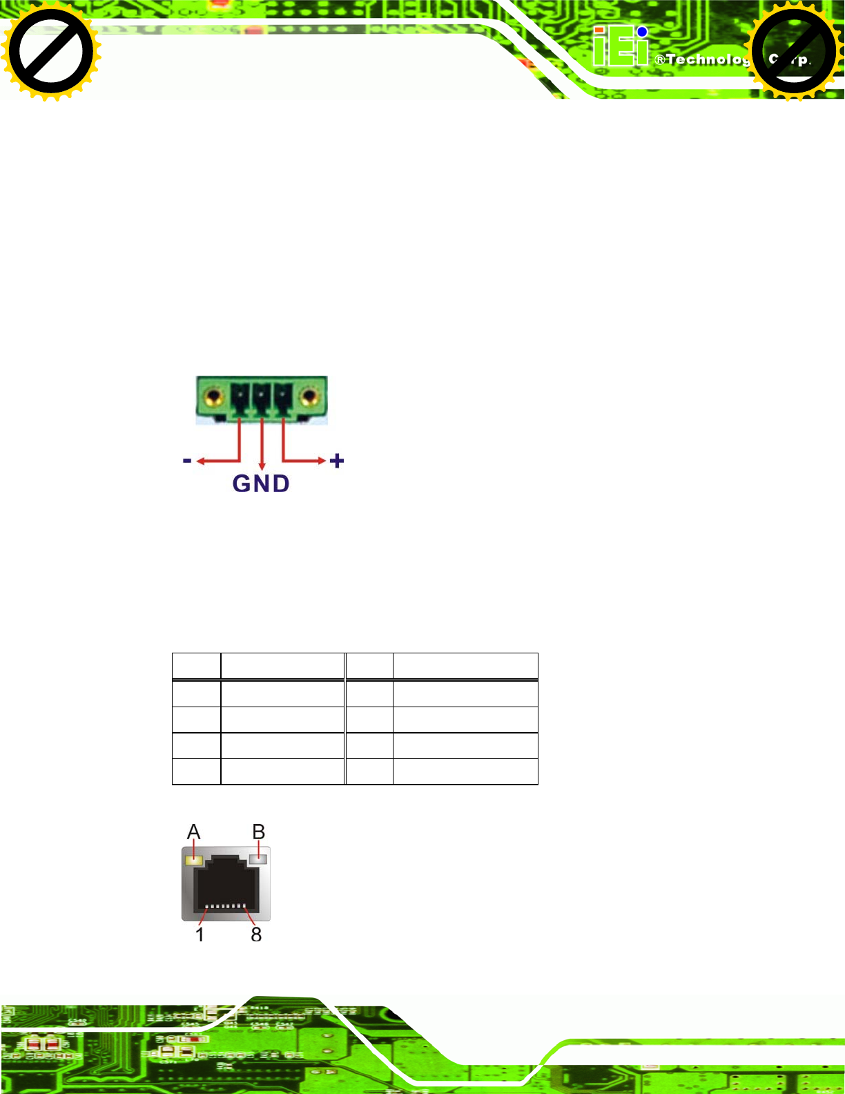
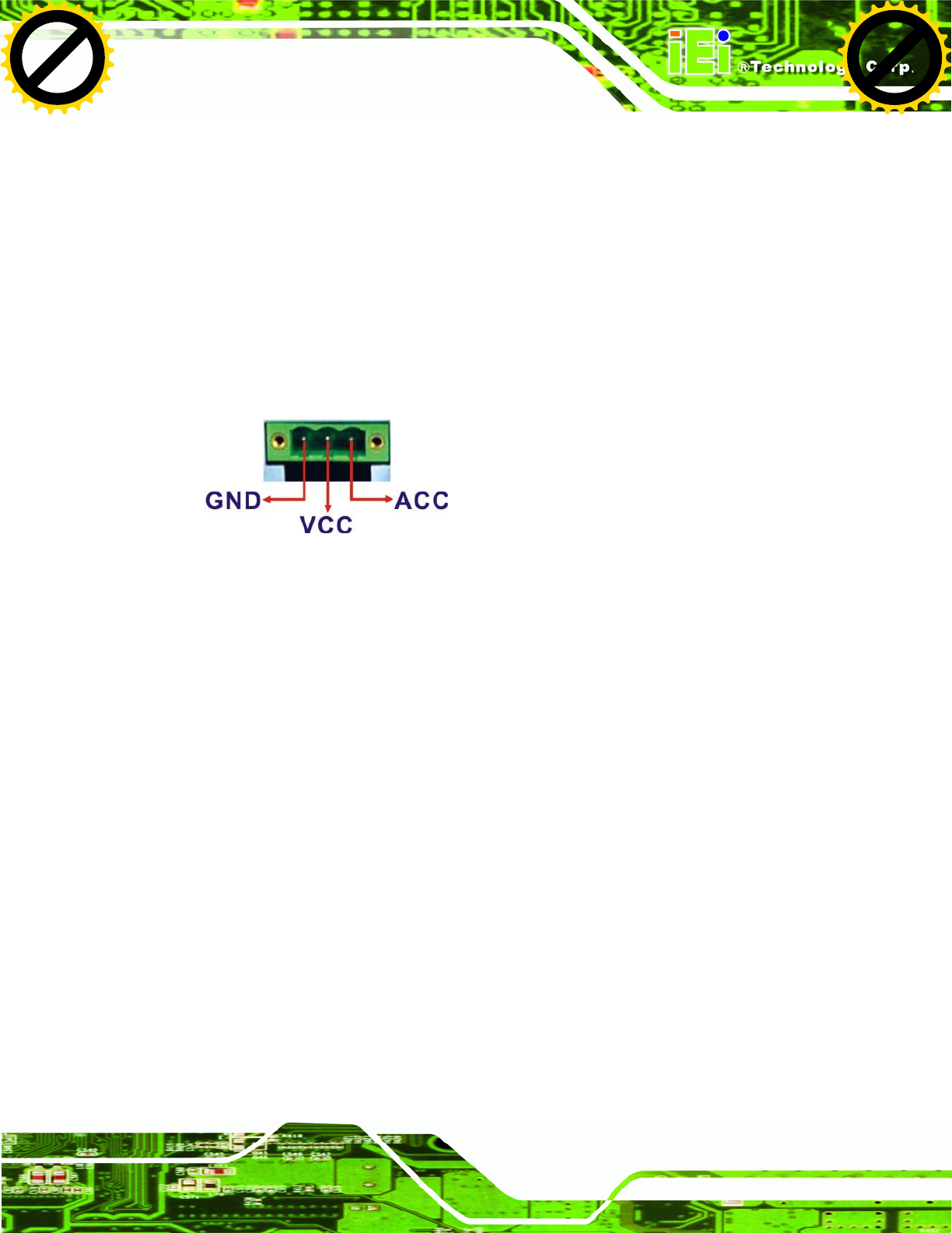
3.6.5 CAN-bus Terminal Block
There is one 3-pin CAN-bus terminal block. The pinouts are shown in Figure 3-18
Figure 3-18: CAN-bus Terminal Block Pinouts
3.6.6 LAN Connector
The LAN connector allows connection to an external network. The pinouts of the RJ-45
LAN connector is shown below.
Pin Description Pin Description
1 MDI0+ 2 MDI0-
3 MDI1+ 4 MDI1-
5 MDI2+ 6 MDI2-
7 MDI3+ 8 MDI3-
Table 3-1: LAN Pinouts
Figure 3-19: RJ-45 Ethernet Connector
Click to buy NOW!
P
D
F
-
X
C
h
a
n
g
e
V
i
e
w
e
r
w
w
w
.
d
o
c
u
-
t
r
a
c
k
.
c
o
m
Click to buy NOW!
P
D
F
-
X
C
h
a
n
g
e
V
i
e
w
e
r
w
w
w
.
d
o
c
u
-
t
r
a
c
k
.
c
o
m
UPC-V312-D525 Panel PC
Page 34
The RJ-45 Ethernet connector has two status LEDs, one green and one yellow. See
Figure 3-19.
LED Description LED Description
A on: linked
blinking: data is being sent/received
B off: 10 Mb/s
green: 100 Mb/s
orange: 1000 Mb/s
Table 3-2: RJ-45 Ethernet Connector LEDs
To connect the UPC-V312-D525 to a network through the RJ-45 LAN connector, follow
the steps below.
Step 1: Locate the RJ-45 connector. The location of the RJ-45 connectors is shown in
Figure 1-4.
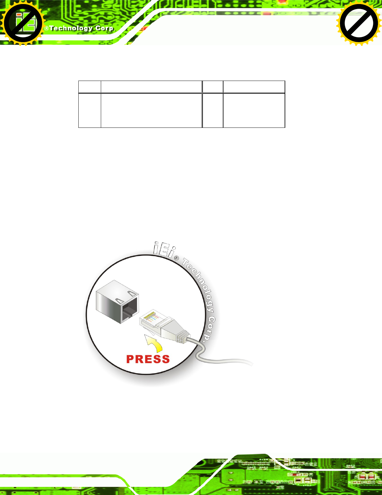
Step 2: Align the connectors. Align the RJ-45 connector on the LAN cable with one of
the RJ-45 connectors on the UPC-V312-D525. See Figure 3-20.
Figure 3-20: LAN Connection
Step 3: Insert the LAN cable RJ-45 connector. Once aligned, gently insert the LAN
cable RJ-45 connector into the on-board RJ-45 connector.
Click to buy NOW!
P
D
F
-
X
C
h
a
n
g
e
V
i
e
w
e
r
w
w
w
.
d
o
c
u
-
t
r
a
c
k
.
c
o
m
Click to buy NOW!
P
D
F
-
X
C
h
a
n
g
e
V
i
e
w
e
r
w
w
w
.
d
o
c
u
-
t
r
a
c
k
.
c
o
m
UPC-V312-D525 Panel PC
Page 35
3.6.7 Power Input 1, 3-pin Terminal Block
CN Label: POWER 1
CN Type: 3-pin terminal block
CN Location: See Figure 1-4
CN Pinouts: See Figure 3-21
Connect the leads of a 9V~36V DC power supply into the terminal block. Make sure that
the power and ground wires are attached to the correct sockets of the connector.
Figure 3-21: 3-pin Terminal Block Pinouts
3.6.8 Power Input 2, DIN Connector
CN Label: POWER 2
CN Type: DIN connector
CN Location: See Figure 1-4
The power connector connects to the 10.5 V ~ 36 V DC power adapter.
3.6.9 RJ-45 RS-232 Serial Port
CN Label: RS 232
CN Type: RJ-45
CN Location: See Figure 1-4
CN Pinouts: See Table 3-3 and Figure 3-22
A RS-232 serial port device can be connected to the RJ-45 RS-232 serial port on the
bottom panel. The pinouts of the RJ-45 RS-232 serial port is shown below.
Click to buy NOW!
P
D
F
-
X
C
h
a
n
g
e
V
i
e
w
e
r
w
w
w
.
d
o
c
u
-
t
r
a
c
k
.
c
o
m
Click to buy NOW!
P
D
F
-
X
C
h
a
n
g
e
V
i
e
w
e
r
w
w
w
.
d
o
c
u
-
t
r
a
c
k
.
c
o
m
UPC-V312-D525 Panel PC
Page 36
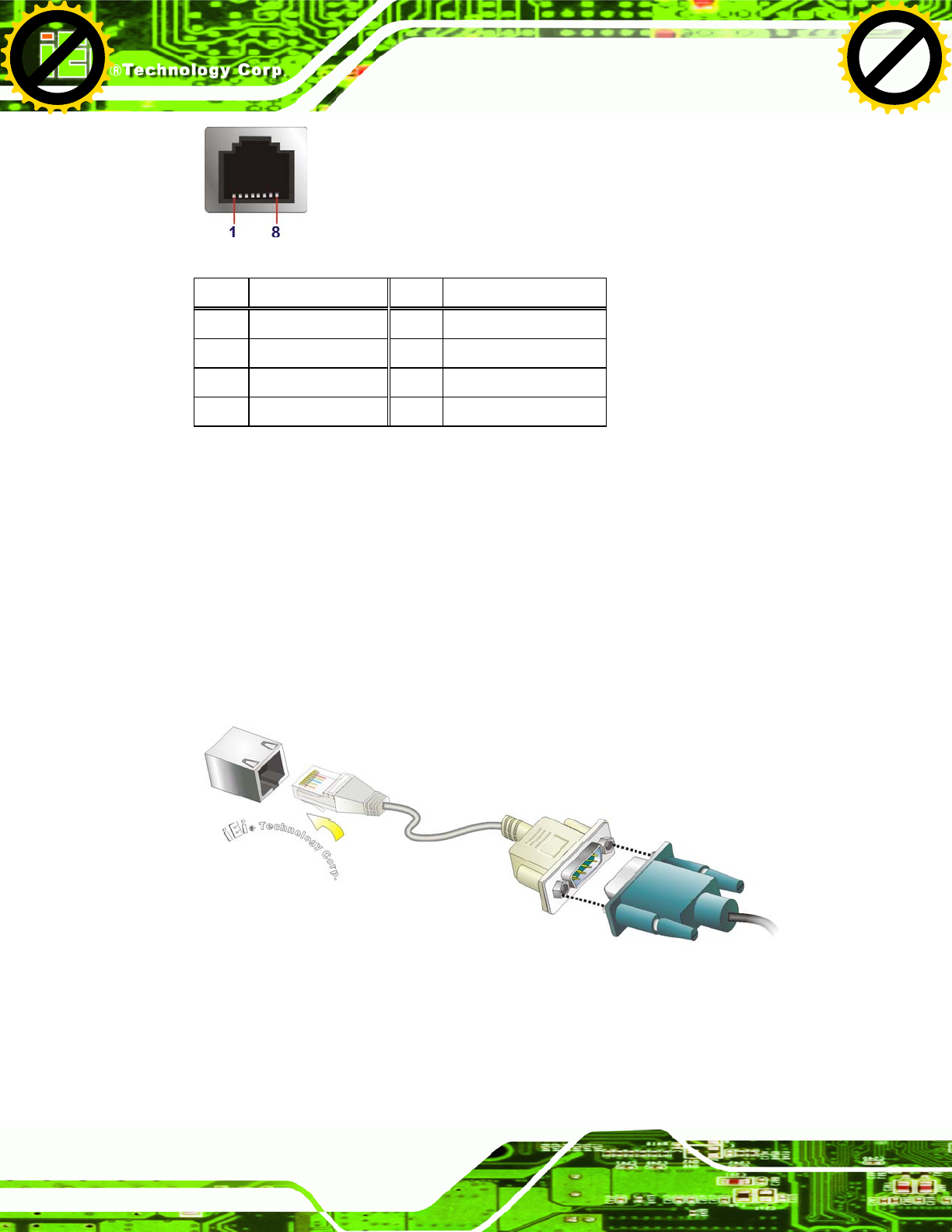
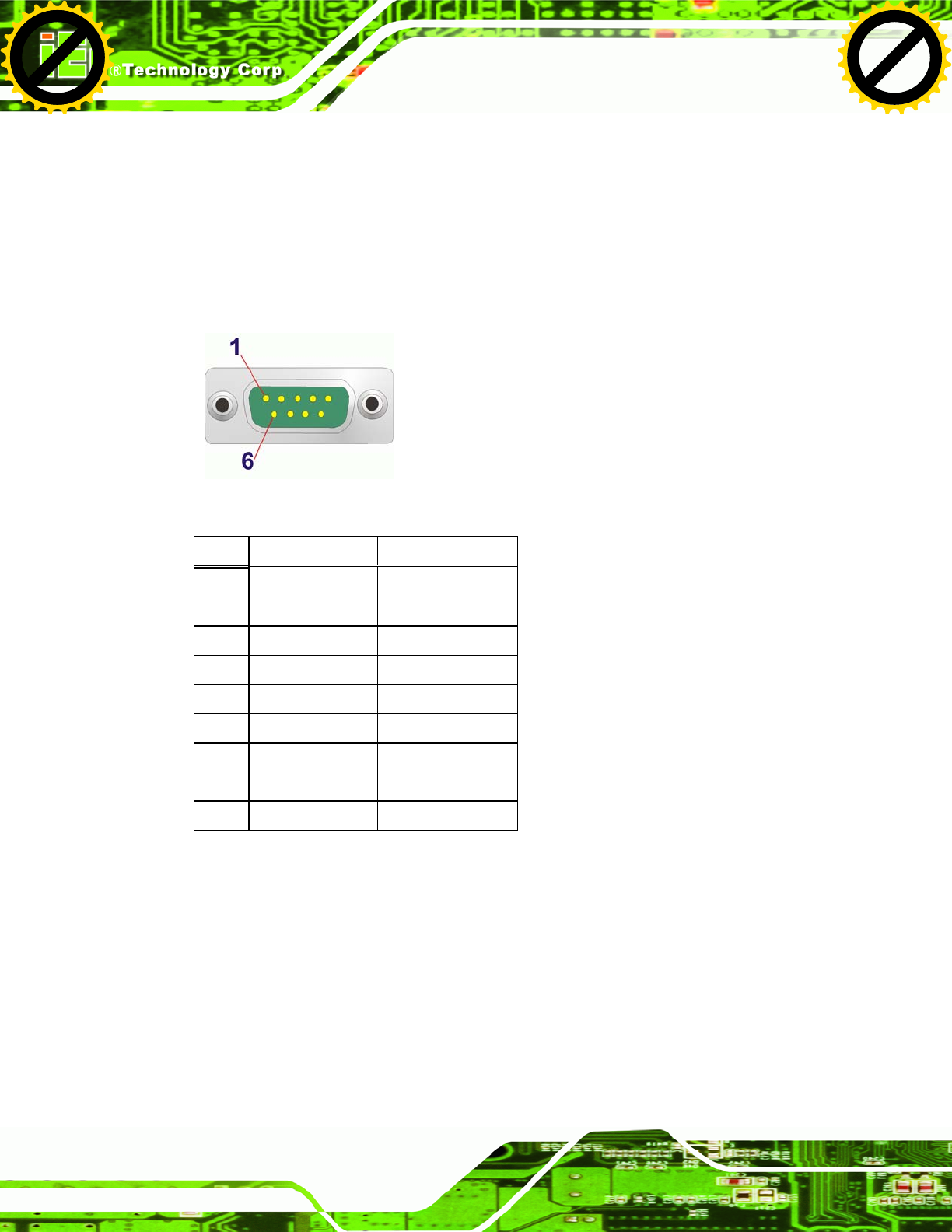
Figure 3-22: RJ-45 RS-232 Serial Port
Pin Description Pin Description
1 NDCD1 5 NTX1
2 NDSR1 6 NCTS1
3. NRX1 7 NDTR1
4. NRTS1 8 NRI1
Table 3-3: RJ-45 RS-232 Serial Port Pinouts
To install the RS-232 devices, follow the steps below.
Step 1: Locate the RJ-45 RS-232 connector. The location of the RJ-45 RS-232
connector is shown in Figure 1-4.
Step 2: Insert the RJ-45 connector. Insert the RJ-45 connector on the RJ-45 to DB-9
COM port cable to the RJ-45 RS-232 connector on the UPC-V312-D525. See
Figure 3-23.
Figure 3-23: RJ-45 RS-232 Serial Device Connection
Step 3: Insert the serial connector. Insert the DB-9 connector of a serial device into
the DB-9 connector on the RJ-45 to DB-9 COM port cable.
Click to buy NOW!
P
D
F
-
X
C
h
a
n
g
e
V
i
e
w
e
r
w
w
w
.
d
o
c
u
-
t
r
a
c
k
.
c
o
m
Click to buy NOW!
P
D
F
-
X
C
h
a
n
g
e
V
i
e
w
e
r
w
w
w
.
d
o
c
u
-
t
r
a
c
k
.
c
o
m
UPC-V312-D525 Panel PC
Page 37
Step 4: Secure the connector. Secure the serial device connector to the external
interface by tightening the two retention screws on either side of the connector.
3.6.10 RS-422/485 Serial Port
CN Label: RS 422/485
CN Type: 4-pin connector
CN Location: See Figure 1-4
CN Pinouts: See Table 3-4 and Figure 3-24
A RS-422/485 serial port device can be connected to the RS-422/485 serial port on the
bottom panel. The pinouts of the RS-422/485 serial port is shown below.
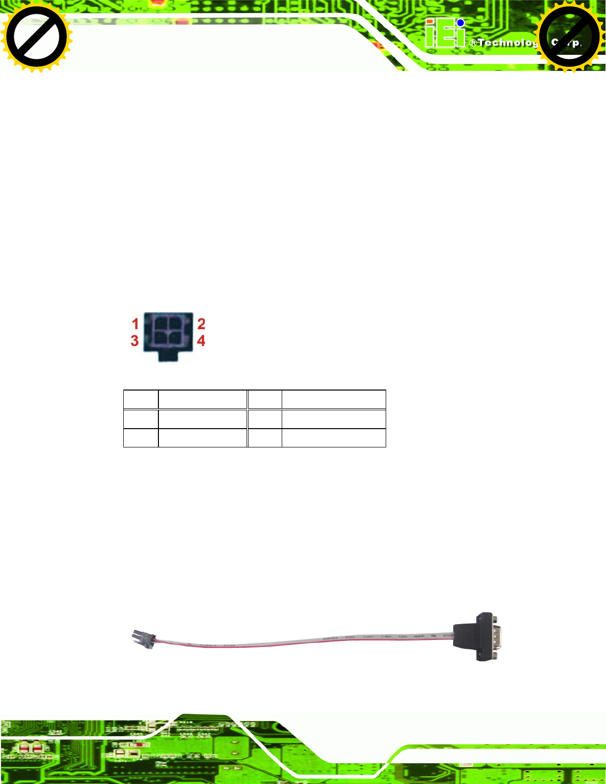
Figure 3-24: RS-422/485 Serial Port
Pin Description Pin Description
1 RXD485+_R 3 TXD485+_R
2 RXD485#_R 4 TXD485#_R
Table 3-4: RS-422/485 Serial Port Pinouts
To install the RS-422/485 devices, follow the steps below.
Step 1: Locate the RS-422/RS485 connector. The location of the RS-422/RS-485
connector is shown in Figure 1-4.
Step 2: Connect the RS-422/485 connector to the RS-422/485 cable. The
RS-422/485 cable can be found in the packing list and is shown in Figure 3-25.
Figure 3-25: RS-422/485 Cable
Click to buy NOW!
P
D
F
-
X
C
h
a
n
g
e
V
i
e
w
e
r
w
w
w
.
d
o
c
u
-
t
r
a
c
k
.
c
o
m
Click to buy NOW!
P
D
F
-
X
C
h
a
n
g
e
V
i
e
w
e
r
w
w
w
.
d
o
c
u
-
t
r
a
c
k
.
c
o
m
UPC-V312-D525 Panel PC
Page 38
Step 3: Insert the serial connector. Insert the DB-9 connector of a serial device into
the DB-9 connector on the RS-422/485 cable.
Step 4: Secure the connector. Secure the serial device connector to the external
interface by tightening the two retention screws on either side of the connector.
Step 5: The DB-9 connector pinouts are listed below.
Figure 3-26: RS-422/485 Serial Port (DB-9)
Pin RS-422 RS-485
1 TX- DATA-
2 TX+ DATA+
3 RX+ --
4 RX- --
5 -- --
6 -- --
7 -- --
8 -- --
9 -- --
Table 3-5: RS-422/485 Serial Port Pinouts
3.6.11 USB Connectors
CN Label: USB
CN Type: USB port
CN Location: See Figure 1-4
CN Pinouts: See Table 3-6
Click to buy NOW!
P
D
F
-
X
C
h
a
n
g
e
V
i
e
w
e
r
w
w
w
.
d
o
c
u
-
t
r
a
c
k
.
c
o
m
Click to buy NOW!
P
D
F
-
X
C
h
a
n
g
e
V
i
e
w
e
r
w
w
w
.
d
o
c
u
-
t
r
a
c
k
.
c
o
m
UPC-V312-D525 Panel PC
Page 39
The USB ports are for attaching USB peripheral devices to the system. The pinouts of the
USB port is shown below.
Pin Description Pin Description
1 VCC 5 VCC
2 DATA- 6 DATA-
3 DATA+ 7 DATA+
4 GROUND 8 GROUND
Table 3-6: USB Port Pinouts
To install a USB device, follow the steps below.
Step 1: Locate the USB connectors. The locations of the USB connectors are shown
in Figure 1-4.
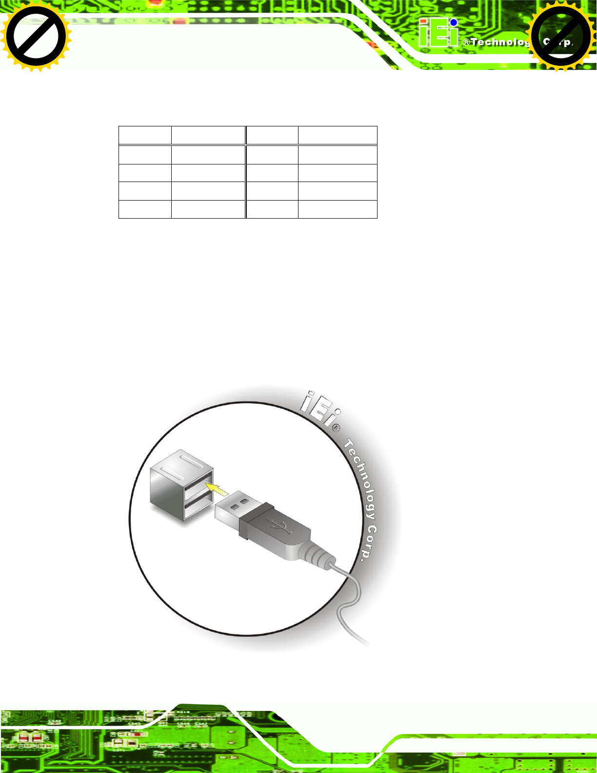
Step 2: Align the connectors. Align the USB device connector with one of the
connectors. See Figure 3-27.
Figure 3-27: USB Device Connection
Click to buy NOW!
P
D
F
-
X
C
h
a
n
g
e
V
i
e
w
e
r
w
w
w
.
d
o
c
u
-
t
r
a
c
k
.
c
o
m
Click to buy NOW!
P
D
F
-
X
C
h
a
n
g
e
V
i
e
w
e
r
w
w
w
.
d
o
c
u
-
t
r
a
c
k
.
c
o
m
UPC-V312-D525 Panel PC
Page 40
Step 3: Insert the device connector. Once aligned, gently insert the USB device
connector into the on-board connector.
3.6.12 VGA Connector
CN Label: VGA
CN Type: 15-pin Female
CN Location: See Figure 1-4
CN Pinouts: See Figure 3-28 and Table 3-7
The VGA connector connects to a monitor that supports dual display. The pinouts of the
VGA connector is shown below.
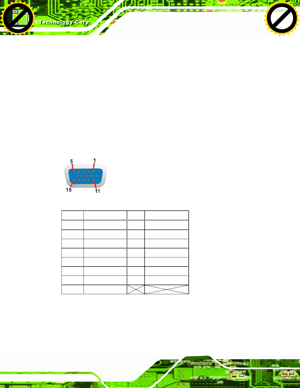
Figure 3-28: VGA Connector
Pin Description Pin Description
1 RED 2 GREEN
3 BLUE 4 NC
5 GND 6 GND
7 GND 8 GND
9 VCC / NC 10 GND
11 NC 12 DDC DAT
13 HSYNC 14 VSYNC
15 DDCCLK
Table 3-7: VGA Connector Pinouts
To connect the UPC-V312-D525 to a second display, follow the steps below,
Step 1: Locate the female DB-15 connector. The location of the female DB-15
connector is shown in Figure 1-4.
Click to buy NOW!
P
D
F
-
X
C
h
a
n
g
e
V
i
e
w
e
r
w
w
w
.
d
o
c
u
-
t
r
a
c
k
.
c
o
m
Click to buy NOW!
P
D
F
-
X
C
h
a
n
g
e
V
i
e
w
e
r
w
w
w
.
d
o
c
u
-
t
r
a
c
k
.
c
o
m
UPC-V312-D525 Panel PC
Page 41
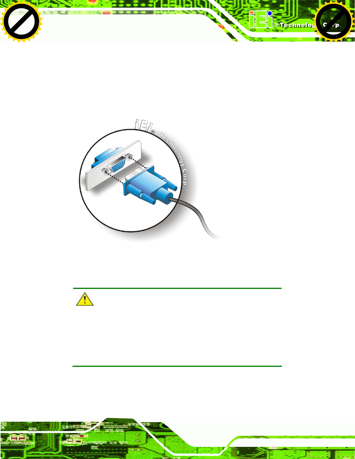
Step 2: Align the VGA connector. Align the male DB-15 connector on the VGA screen
cable with the female DB-15 connector on the external peripheral interface.
Step 3: Insert the VGA connector. Once the connectors are properly aligned with the
insert the male connector from the VGA screen into the female connector on the
UPC-V312-D525. See Figure 3-29.
Figure 3-29: VGA Connector
CAUTION:
It is suggested that not to open the rear cover and replace any
components. If the components fail, it must be shipped back to IEI to
be replaced. If the system has failed, please contact the system
vendor, reseller or an IEI sales person directly.
Click to buy NOW!
P
D
F
-
X
C
h
a
n
g
e
V
i
e
w
e
r
w
w
w
.
d
o
c
u
-
t
r
a
c
k
.
c
o
m
Click to buy NOW!
P
D
F
-
X
C
h
a
n
g
e
V
i
e
w
e
r
w
w
w
.
d
o
c
u
-
t
r
a
c
k
.
c
o
m
UPC-V312-D525 Panel PC
Page 42
3.7 Redundant Power
The UPC-V312-D525 is a system that supports redundant power. The redundant power
input increases the reliability of the system while preventing data loss and system
corruption from sudden power failure. The system can instantly and uninterruptedly switch
to the second power input when the main power is unavailable or in low voltage capacity.
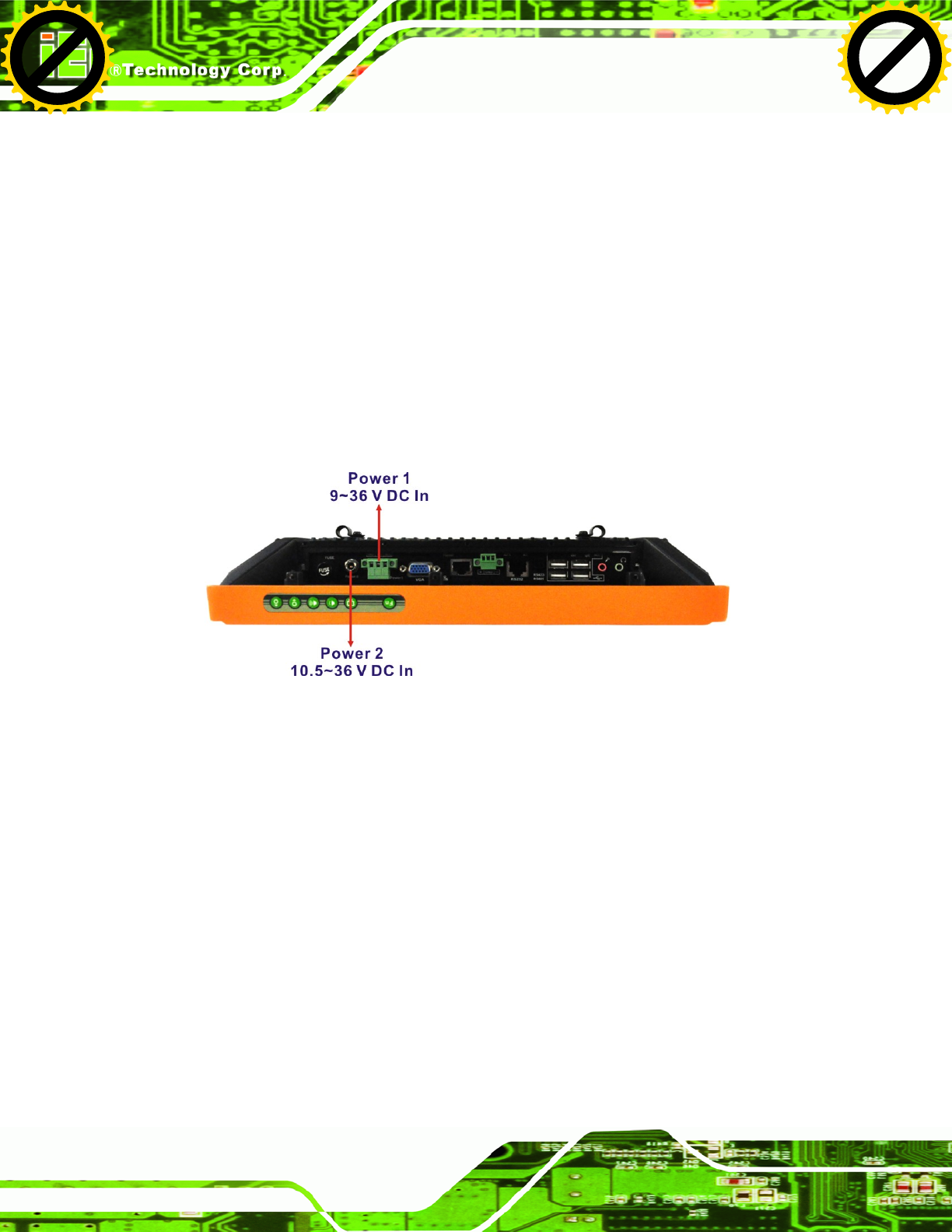
There are two power connectors on the bottom panel. Power 1 connector is a 3-pin
terminal block that supports ACC On signal. Power 2 connector is a DIN connector that
can directly connect to a power adapter. The supported power input voltages are:
Power 1 (Terminal block): 9 V (+/-3 V) ~ 36 V
Power 2 (DC jack): 10.5 V (+/-0.3 V) ~ 36 V
Figure 3-30: Power Connectors
When the system is in ACC On mode, the main power input is from the Power 1 connector.
When the system is in ACC Off mode, the main power input is from the Power 2 connector.
The ACC on/off mode is selected by the ACC on/off switch on the bottom panel.
(Figure 3-16).
The following sections describe how redundant power works in ACC On mode and ACC
Off mode.
Click to buy NOW!
P
D
F
-
X
C
h
a
n
g
e
V
i
e
w
e
r
w
w
w
.
d
o
c
u
-
t
r
a
c
k
.
c
o
m
Click to buy NOW!
P
D
F
-
X
C
h
a
n
g
e
V
i
e
w
e
r
w
w
w
.
d
o
c
u
-
t
r
a
c
k
.
c
o
m
UPC-V312-D525 Panel PC
Page 43
3.7.1 ACC ON
NOTE:
In ACC On mode, the Power 1 connector must connect to the ACC on
signal to be able to control system power.
The ACC On mode is designed for vehicle applications. When the UPC-V312-D525 is in
ACC On mode, the main power input is the Power 1 connector and the backup power is
from the Power 2 connector.
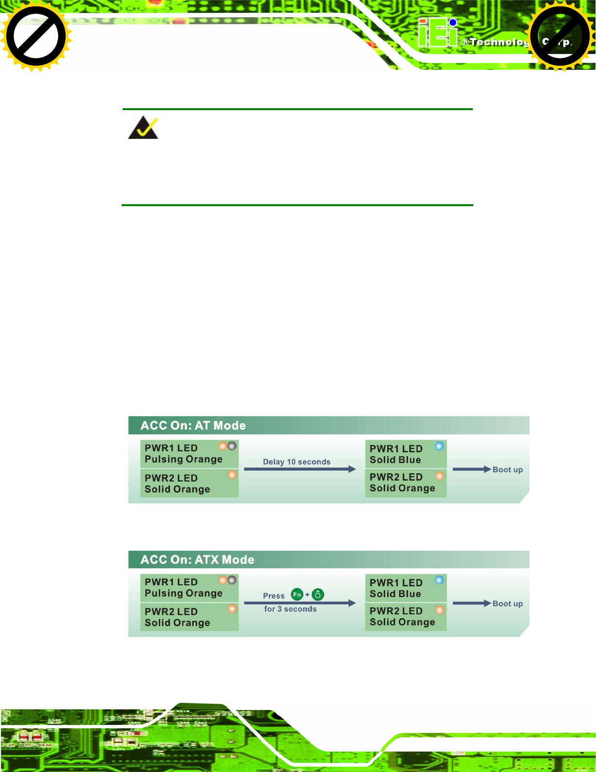
3.7.1.1 Boot-up
When both power connectors are connected to the power source with over 9 V, the two
power LEDs on the front panel remain off until the ACC ON signal jumps from low to
high. The user can choose AT power mode or ATX power mode to control the system.
The following flow diagrams show the boot-up process and the LED status in AT and ATX
power modes.
Figure 3-31: ACC On: AT Mode
Figure 3-32: ACC On: ATX Mode
Click to buy NOW!
P
D
F
-
X
C
h
a
n
g
e
V
i
e
w
e
r
w
w
w
.
d
o
c
u
-
t
r
a
c
k
.
c
o
m
Click to buy NOW!
P
D
F
-
X
C
h
a
n
g
e
V
i
e
w
e
r
w
w
w
.
d
o
c
u
-
t
r
a
c
k
.
c
o
m
UPC-V312-D525 Panel PC
Page 44
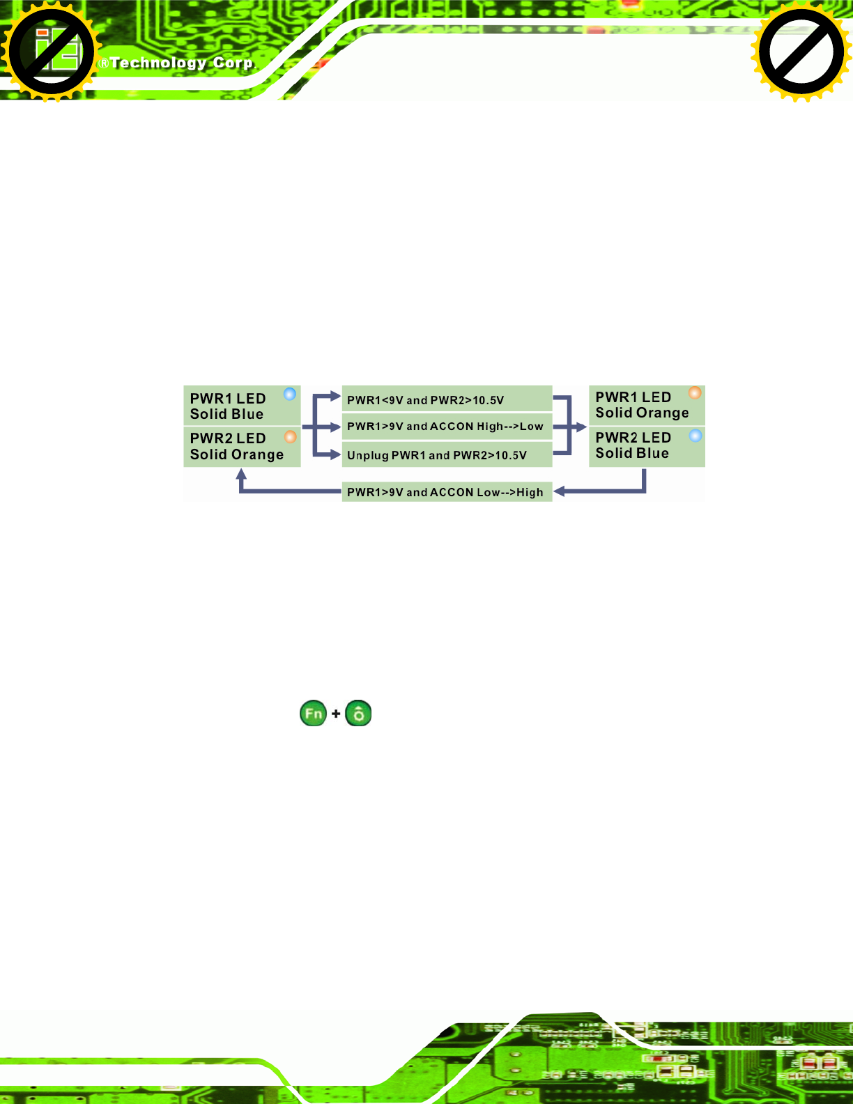
3.7.1.2 Switch to Backup Power
During operation, system power will switch from Power 1 to Power 2 automatically when
the following situations occur:
Power 1 < 9V and Power 2 > 10.5V
Power 1 > 9V, but the ACC ON signal jump from high to low
Power 1 is unplugged and Power 2 > 10.5V
The following flow diagram shows how the power is switched between Power 1 and
Power 2 and their LED statuses.
Figure 3-33: ACC On: Switch Between PWR1 and PWR2
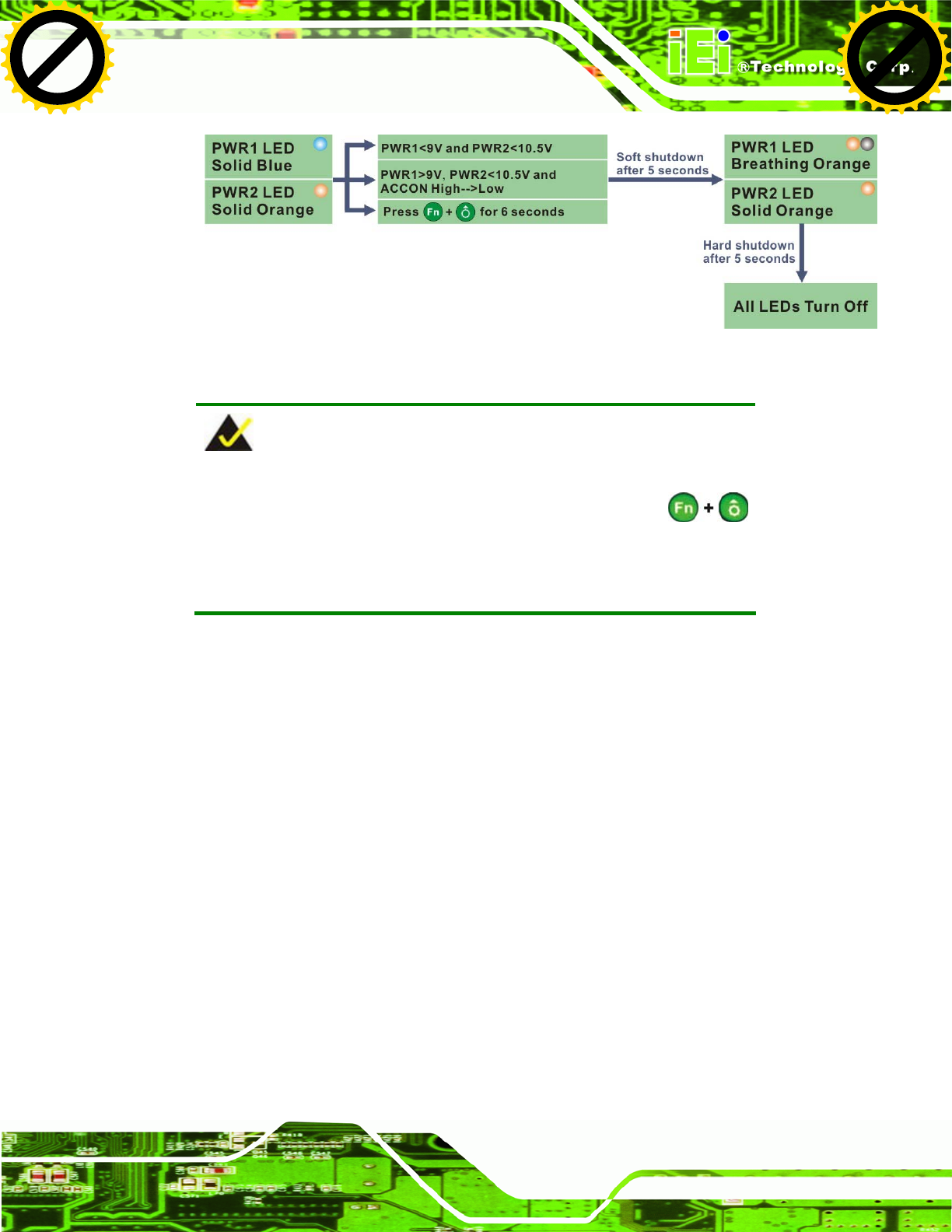
3.7.1.3 Shutdown
The system will shutdown in the following situations:
Power 1 < 9V and Power 2 < 10.5V
Power 1 > 9V, Power 2 < 10.5V and ACC ON signal jump from high to low
Press buttons for 6 seconds
The following flow diagram shows the system shutdown process and the LED statuses.
Click to buy NOW!
P
D
F
-
X
C
h
a
n
g
e
V
i
e
w
e
r
w
w
w
.
d
o
c
u
-
t
r
a
c
k
.
c
o
m
Click to buy NOW!
P
D
F
-
X
C
h
a
n
g
e
V
i
e
w
e
r
w
w
w
.
d
o
c
u
-
t
r
a
c
k
.
c
o
m
UPC-V312-D525 Panel PC
Page 45
Figure 3-34: ACC On: Shutdown
NOTE:
To turn on the system in ATX power mode, press the
button for three seconds. Press these two buttons for six seconds to
turn off the system.
3.7.2 ACC OFF
When the UPC-V312-D525 is in ACC Off mode, the main power input is the Power 2
connector and the backup power is from the Power 1 connector.
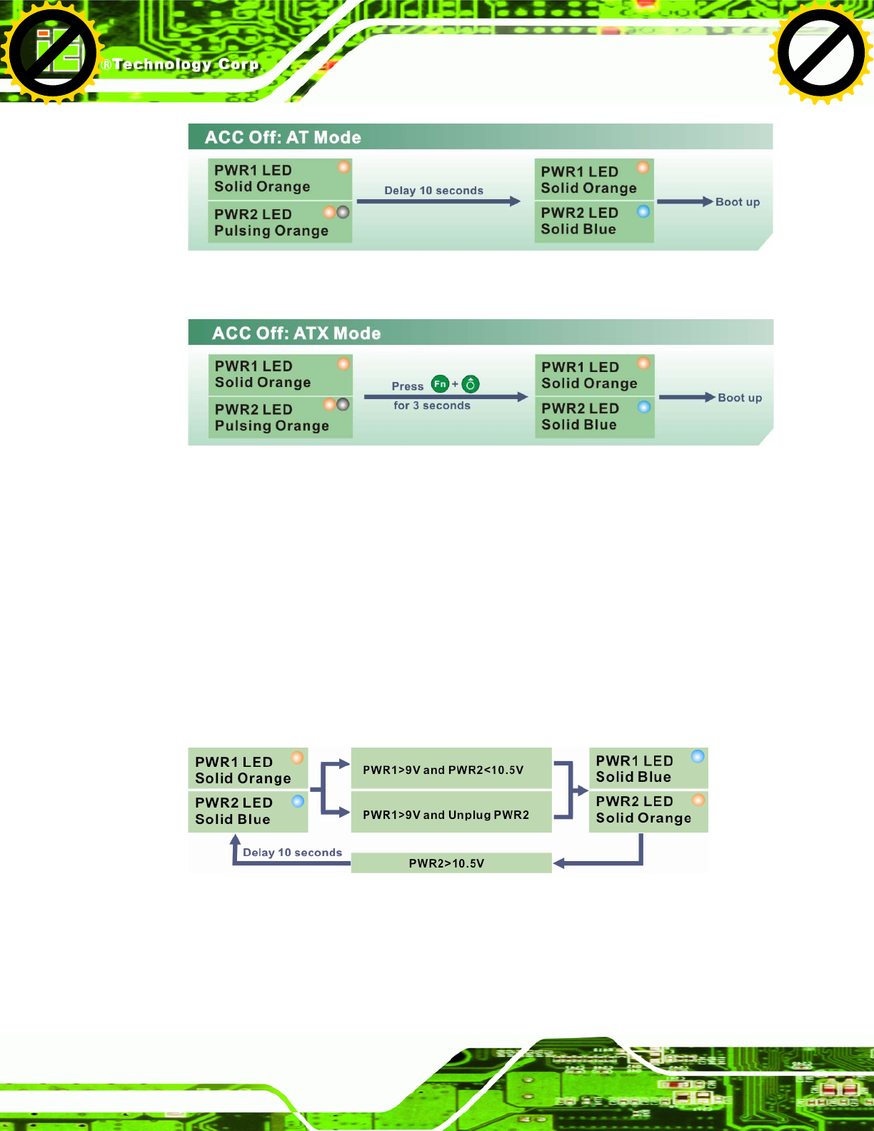
3.7.2.1 Boot-up
When both power connectors are connected to the power source with over 9 V, the two
power LEDs on the front panel turn on. The user can choose AT power mode or ATX
power mode to control the system. The following flow diagrams show the boot-up process
and the LED status in AT and ATX power modes.
Click to buy NOW!
P
D
F
-
X
C
h
a
n
g
e
V
i
e
w
e
r
w
w
w
.
d
o
c
u
-
t
r
a
c
k
.
c
o
m
Click to buy NOW!
P
D
F
-
X
C
h
a
n
g
e
V
i
e
w
e
r
w
w
w
.
d
o
c
u
-
t
r
a
c
k
.
c
o
m
UPC-V312-D525 Panel PC
Page 46
Figure 3-35: ACC Off: AT Mode
Figure 3-36: ACC Off: ATX Mode
3.7.2.2 Switch to Backup Power
During operation, system power switches from Power 2 to Power 1 automatically when the
following situations occur:
Power 2 < 10.5V and Power 1 > 9V
Power 2 is unplugged and Power 1 > 9V
The following flow diagram shows how the power is switched between Power 2 and
Power 1 and their LED statuses.
Figure 3-37: ACC Off: Switch Between PWR1 and PWR2
Click to buy NOW!
P
D
F
-
X
C
h
a
n
g
e
V
i
e
w
e
r
w
w
w
.
d
o
c
u
-
t
r
a
c
k
.
c
o
m
Click to buy NOW!
P
D
F
-
X
C
h
a
n
g
e
V
i
e
w
e
r
w
w
w
.
d
o
c
u
-
t
r
a
c
k
.
c
o
m
UPC-V312-D525 Panel PC
Page 47
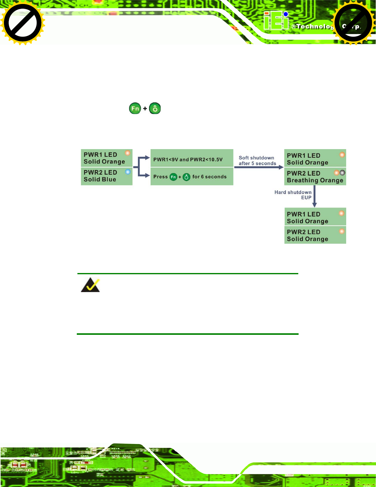
3.7.2.3 Shutdown
The system will shutdown in the following situations:
Power 2 < 10.5V and Power 1 < 9V
Press buttons for 6 seconds
The following flow diagram shows the system shutdown process and the LED statuses.
Figure 3-38: ACC Off: Shutdown
NOTE:
The power LED turns off when the power cable is unplugged from the
system.
Click to buy NOW!
P
D
F
-
X
C
h
a
n
g
e
V
i
e
w
e
r
w
w
w
.
d
o
c
u
-
t
r
a
c
k
.
c
o
m
Click to buy NOW!
P
D
F
-
X
C
h
a
n
g
e
V
i
e
w
e
r
w
w
w
.
d
o
c
u
-
t
r
a
c
k
.
c
o
m
UPC-V312-D525 Panel PC
Page 48
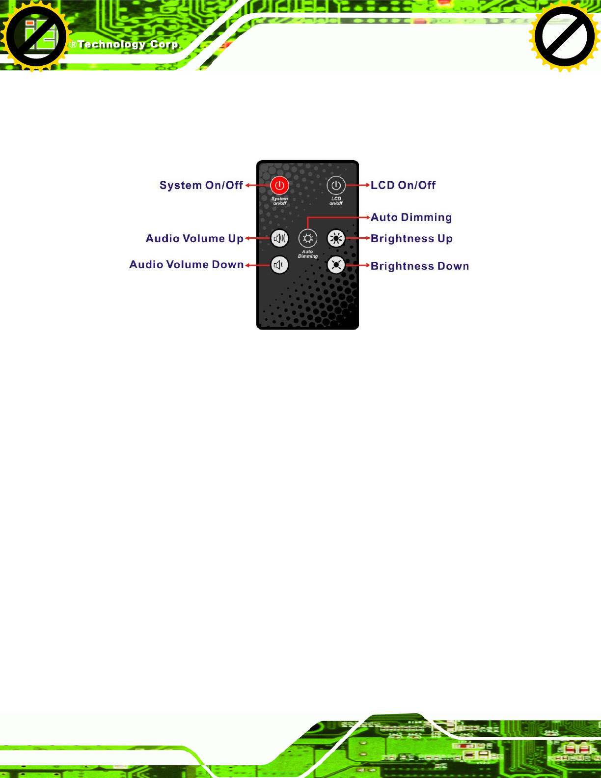
3.8 Remote Control
The UPC-V312-D525 comes with a remote control for easy configuration. 6Figure 3-39
shows the remote control and its function keys.
Figure 3-39: Remote Control
System On/Off: Press this button to turn the UPC-V312-D525 on or off.
LCD On/Off. Press this button to turn the LCD monitor on or off.
Auto-Dimming. Press this button to turn the auto-dimming function on or off.
Brightness. Use these control buttons to adjust the brightness of the LCD
screen.
Volume. Press these buttons to adjust the audio volume level.
Click to buy NOW!
P
D
F
-
X
C
h
a
n
g
e
V
i
e
w
e
r
w
w
w
.
d
o
c
u
-
t
r
a
c
k
.
c
o
m
Click to buy NOW!
P
D
F
-
X
C
h
a
n
g
e
V
i
e
w
e
r
w
w
w
.
d
o
c
u
-
t
r
a
c
k
.
c
o
m