IEI Integration 410UPC-V312 PANEL PC User Manual UPC V312 D525 Panel PC
IEI Integration Corp. PANEL PC UPC V312 D525 Panel PC
Contents
- 1. UPC-V312-D525_User Manual_Rev1_part3
- 2. UPC-V312-D525_User Manual_Rev1_part2
UPC-V312-D525_User Manual_Rev1_part3

UPC-V312-D525 Panel PC
Page 50
4.1 Introduction
The BIOS is programmed onto the BIOS chip. The BIOS setup program allows changes to
certain system settings. This chapter outlines the options that can be changed.
4.1.1 Starting Setup
The UEFI BIOS is activated when the computer is turned on. The setup program can be
activated in one of two ways.
1. Press the DELETE or F2 key as soon as the system is turned on or
2. Press the DELETE or F2 key when the “Press DELETE or F2 to enter SETUP”
message appears on the screen. 0.
If the message disappears before the DELETE or F2 key is pressed, restart the computer
and try again.
4.1.2 Using Setup
Use the arrow keys to highlight items, press ENTER to select, use the PageUp and
PageDown keys to change entries, press F1 for help and press ESC to quit. Navigation
keys are shown in the following table.
Key Function
Up arrow Move to the item above
Down arrow Move to the item below
Left arrow Move to the item on the left hand side
Right arrow Move to the item on the right hand side
+ Increase the numeric value or make changes
- Decrease the numeric value or make changes
Page up Move to the next page
Page down Move to the previous page
Click to buy NOW!
P
D
F
-
X
C
h
a
n
g
e
V
i
e
w
e
r
w
w
w
.
d
o
c
u
-
t
r
a
c
k
.
c
o
m
Click to buy NOW!
P
D
F
-
X
C
h
a
n
g
e
V
i
e
w
e
r
w
w
w
.
d
o
c
u
-
t
r
a
c
k
.
c
o
m

UPC-V312-D525 Panel PC
Page 51
Key Function
Esc Main Menu – Quit and do not save changes into CMOS
Status Page Setup Menu and Option Page Setup Menu --
Exit current page and return to Main Menu
F1 General help, only for Status Page Setup Menu and Option
Page Setup Menu
F9 Load optimized defaults
F10 Save changes and Exit BIOS
Table 4-1: BIOS Navigation Keys
4.1.3 Getting Help
When F1 is pressed a small help window describing the appropriate keys to use and the
possible selections for the highlighted item appears. To exit the Help Window press ESC or
the F1 key again.
4.1.4 BIOS Menu Bar
The menu bar on top of the BIOS screen has the following main items:
Main – Changes the basic system configuration.
Advanced – Changes the advanced system settings.
Chipset – Changes the chipset settings.
Boot – Changes the system boot configuration.
Save & Exit – Selects exit options and loads default settings
The following sections completely describe the configuration options found in the menu
items at the top of the BIOS screen and listed above.
Click to buy NOW!
P
D
F
-
X
C
h
a
n
g
e
V
i
e
w
e
r
w
w
w
.
d
o
c
u
-
t
r
a
c
k
.
c
o
m
Click to buy NOW!
P
D
F
-
X
C
h
a
n
g
e
V
i
e
w
e
r
w
w
w
.
d
o
c
u
-
t
r
a
c
k
.
c
o
m
UPC-V312-D525 Panel PC
Page 52
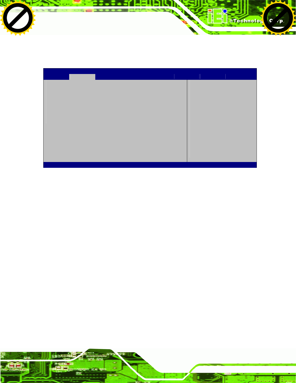
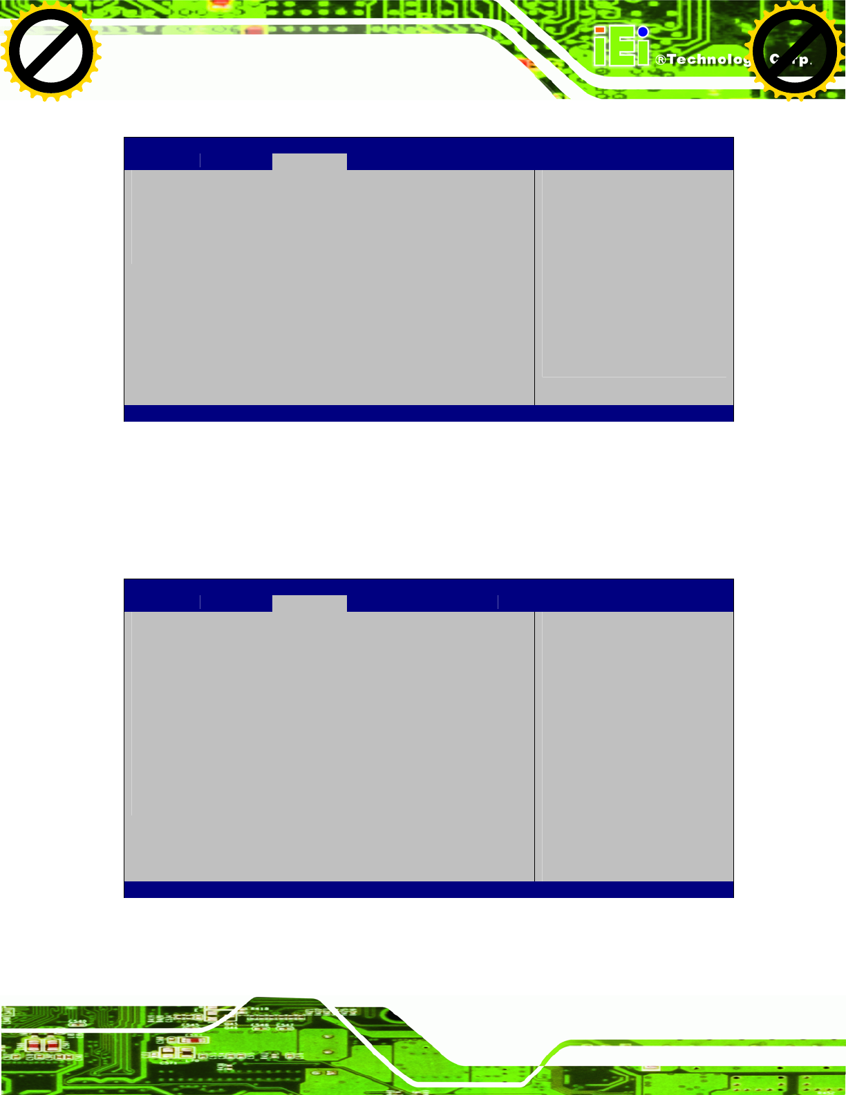
4.2 Main
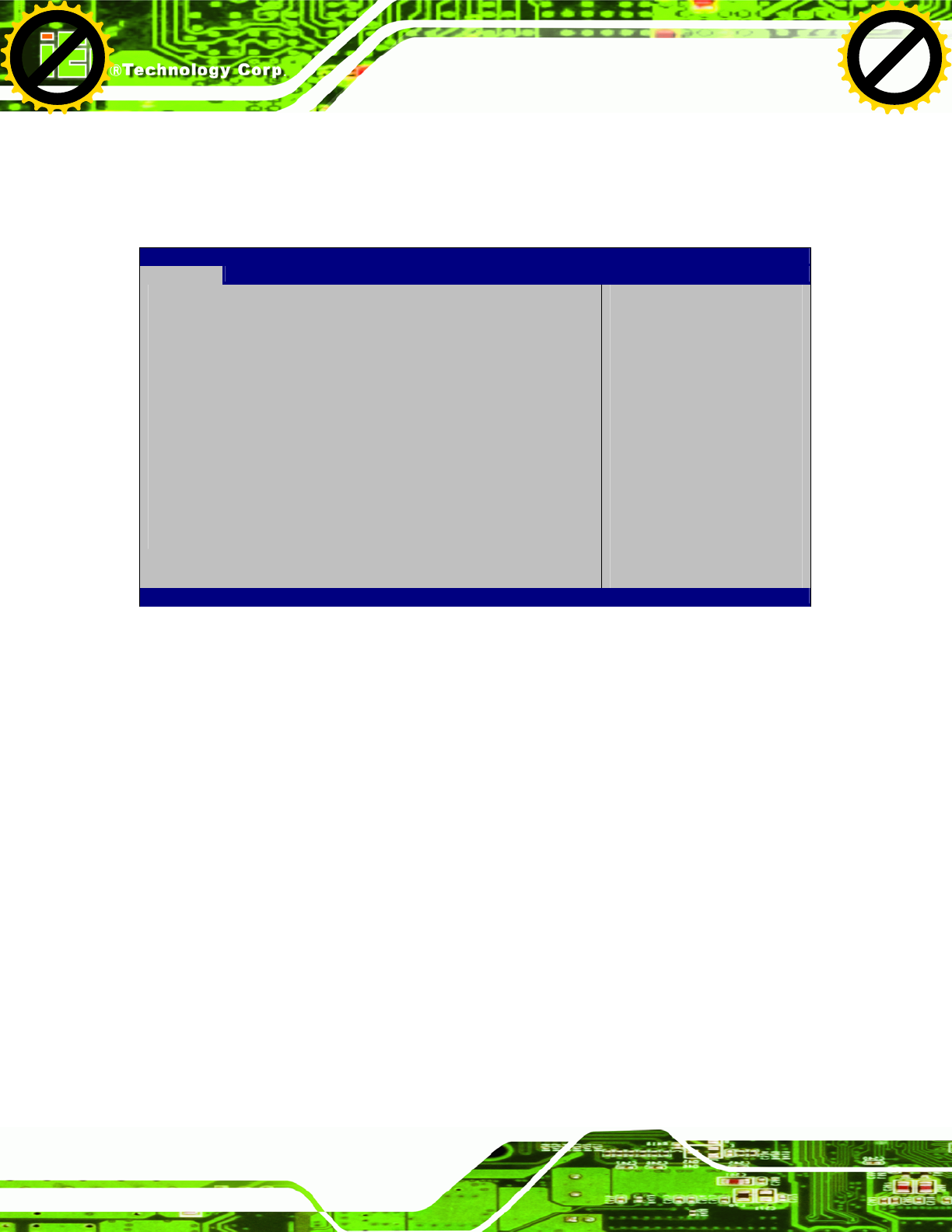
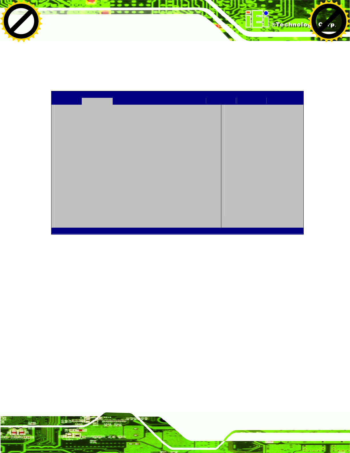
The Main BIOS menu (BIOS Menu 1) appears when the BIOS Setup program is entered.
The Main menu gives an overview of the basic system information.
Aptio Setup Utility – Copyright (C) 2010 American Megatrends, Inc.
Main Advanced Chipset Boot Save & Exit
BIOS Information
BIOS Vendor American Megatrends
Core Version 4.6.4.0 0.20
Compliency UEFI 2.0
Project Version SC80AR13.ROM
Build Date 08/03/2011 16:42:05
IWDD Vender ICP
IWDD Version SC80ER12.bin
System Date [Tue 05/06/2008]
System Time [14:20:27]
Access Level Administrator
S
et the Time. Use Tab to
switch between Time
elements.
----------------------
ÅÆ
: Select Screen
↑ ↓: Select Item
Enter Select
+/-: Change Opt.
F1: General Help
F2: Previous Values
F3: Optimized Defaults
F4: Save & Exit
ESC: Exit
Version 2.02.1205. Copyright (C) 2010 American Megatrends, Inc.
BIOS Menu 1: Main
Î BIOS Information
The BIOS Information lists a brief summary of the BIOS. The fields in BIOS Information
cannot be changed. The items shown in the system overview include:
BIOS Vendor: Installed BIOS vendor
Core Version: Current BIOS version
Compliency: compliant UEFI specification version
Project Version: the board version
Build Date: Date the current BIOS version was made
Î System Date [xx/xx/xx]
Use the System Date option to set the system date. Manually enter the day, month and
year.
Click to buy NOW!
P
D
F
-
X
C
h
a
n
g
e
V
i
e
w
e
r
w
w
w
.
d
o
c
u
-
t
r
a
c
k
.
c
o
m
Click to buy NOW!
P
D
F
-
X
C
h
a
n
g
e
V
i
e
w
e
r
w
w
w
.
d
o
c
u
-
t
r
a
c
k
.
c
o
m
UPC-V312-D525 Panel PC
Page 53
Î System Time [xx:xx:xx]
Use the System Time option to set the system time. Manually enter the hours, minutes
and seconds.
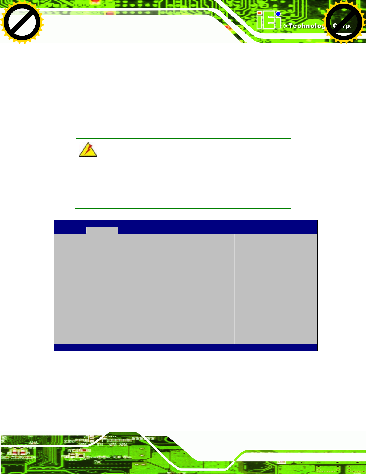
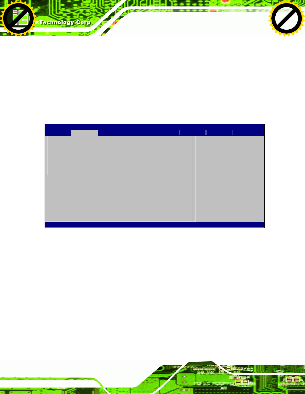
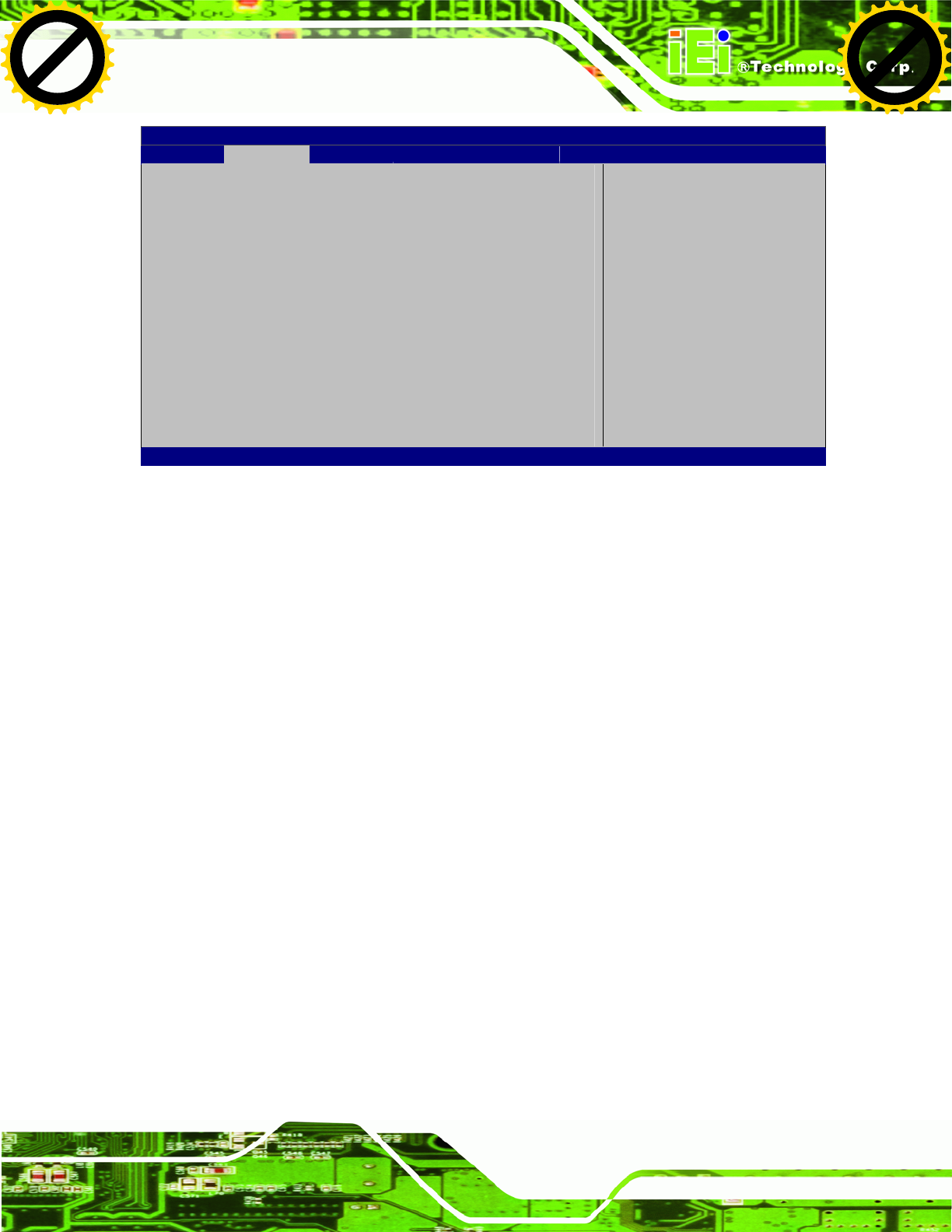
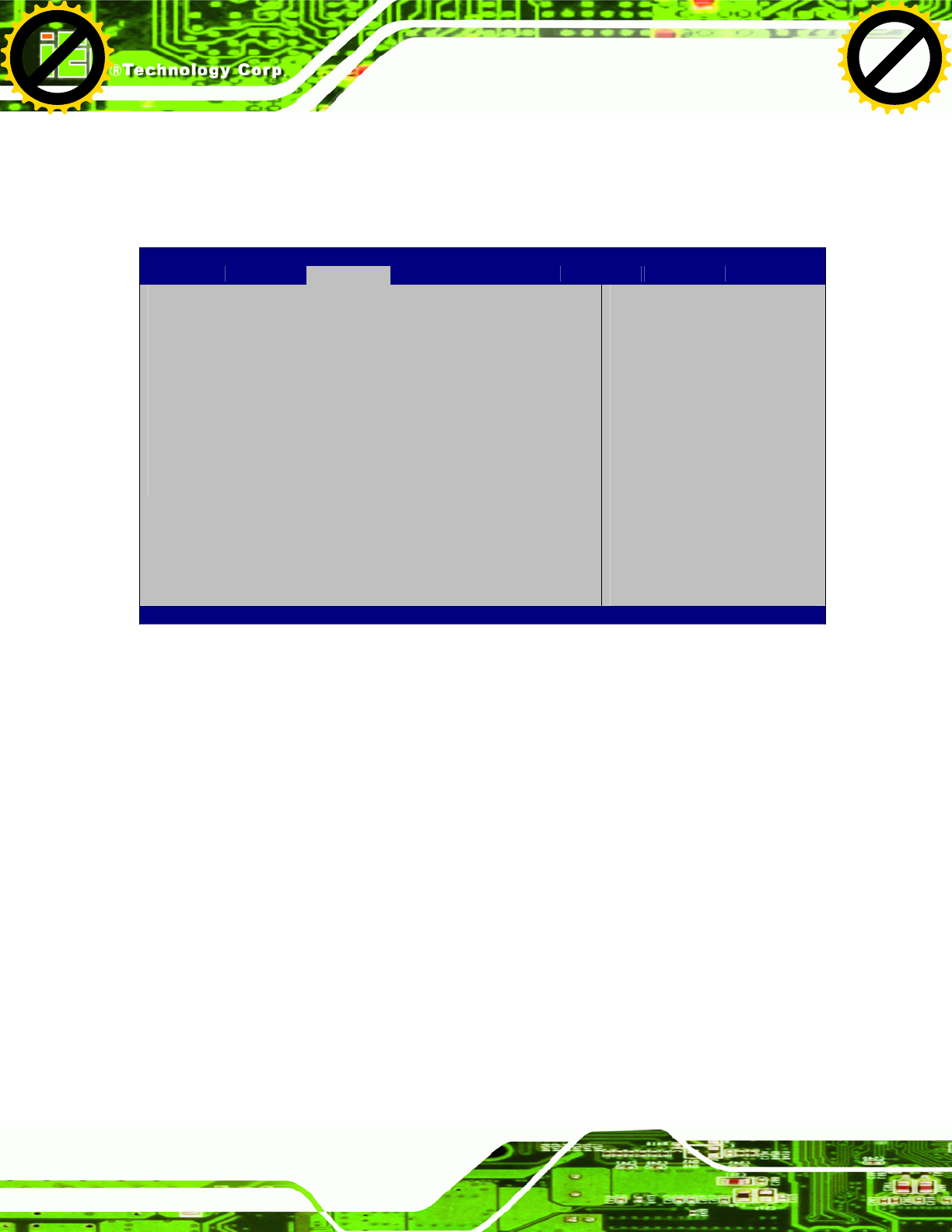
4.3 Advanced
Use the Advanced menu (BIOS Menu 2) to configure the CPU and peripheral devices
through the following sub-menus:
WARNING!
Setting the wrong values in the sections below may cause the system
to malfunction. Make sure that the settings made are compatible with
the hardware.
Aptio Setup Utility – Copyright (C) 2010 American Megatrends, Inc.
Main Advanced Chipset Boot Save & Exit
> ACPI Settings
> CPU Configuration
> IDE Configuration
> USB Configuration
> Super IO Configuration
> H/M Monitor
> Serial Port Console Redirection
> iEi Feature
System ACPI Parameters
----------------------
ÅÆ
: Select Screen
↑ ↓: Select Item
Enter Select
+/-: Change Opt.
F1: General Help
F2: Previous Values
F3: Optimized Defaults
F4: Save & Exit
ESC: Exit
Version 2.02.1205. Copyright (C) 2010 American Megatrends, Inc.
BIOS Menu 2: Advanced
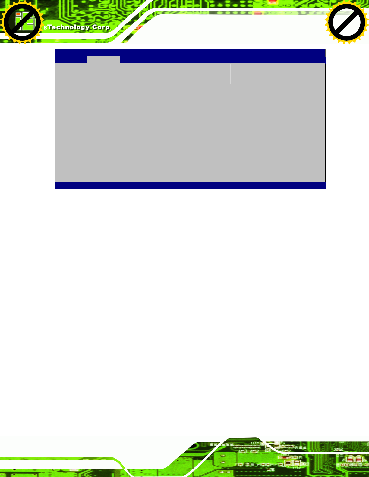
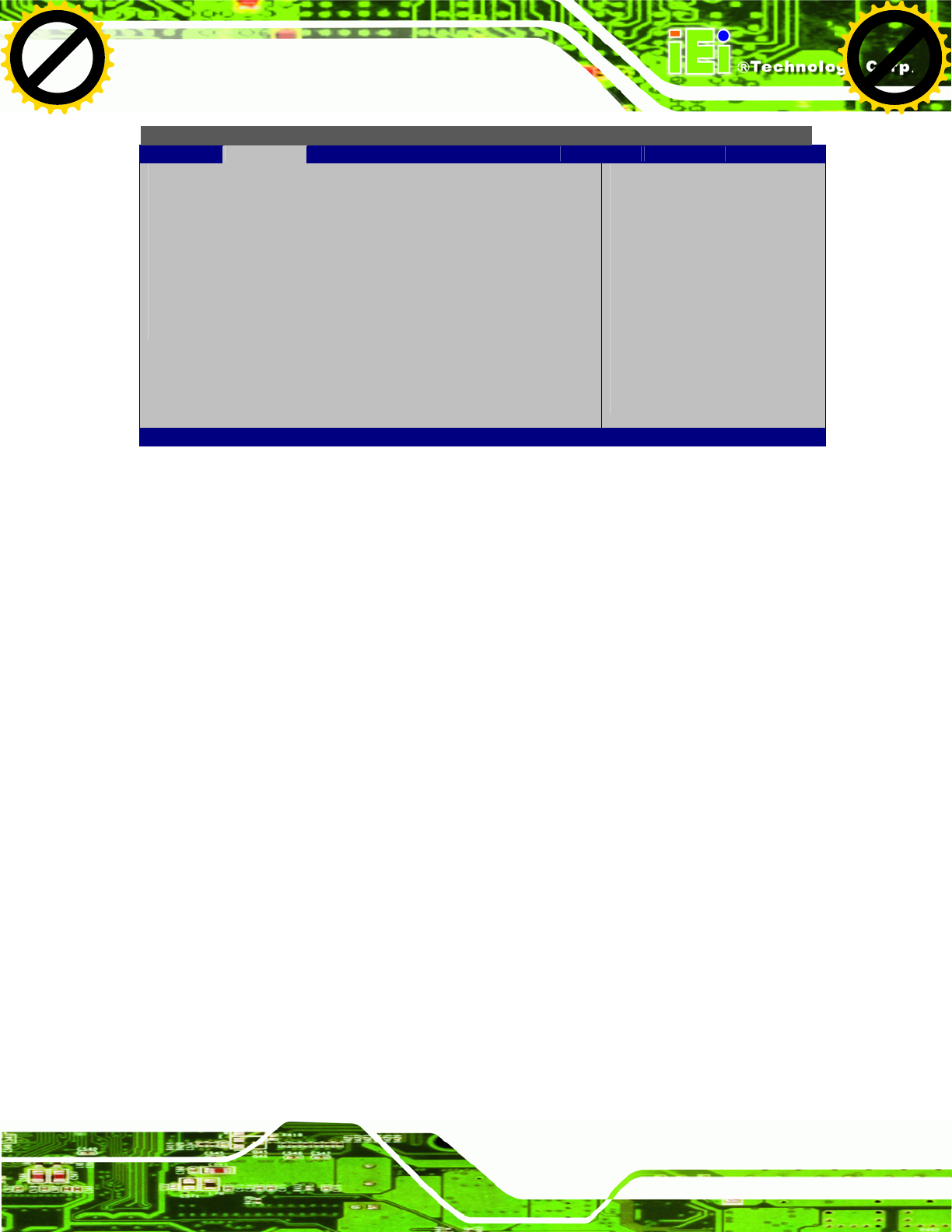
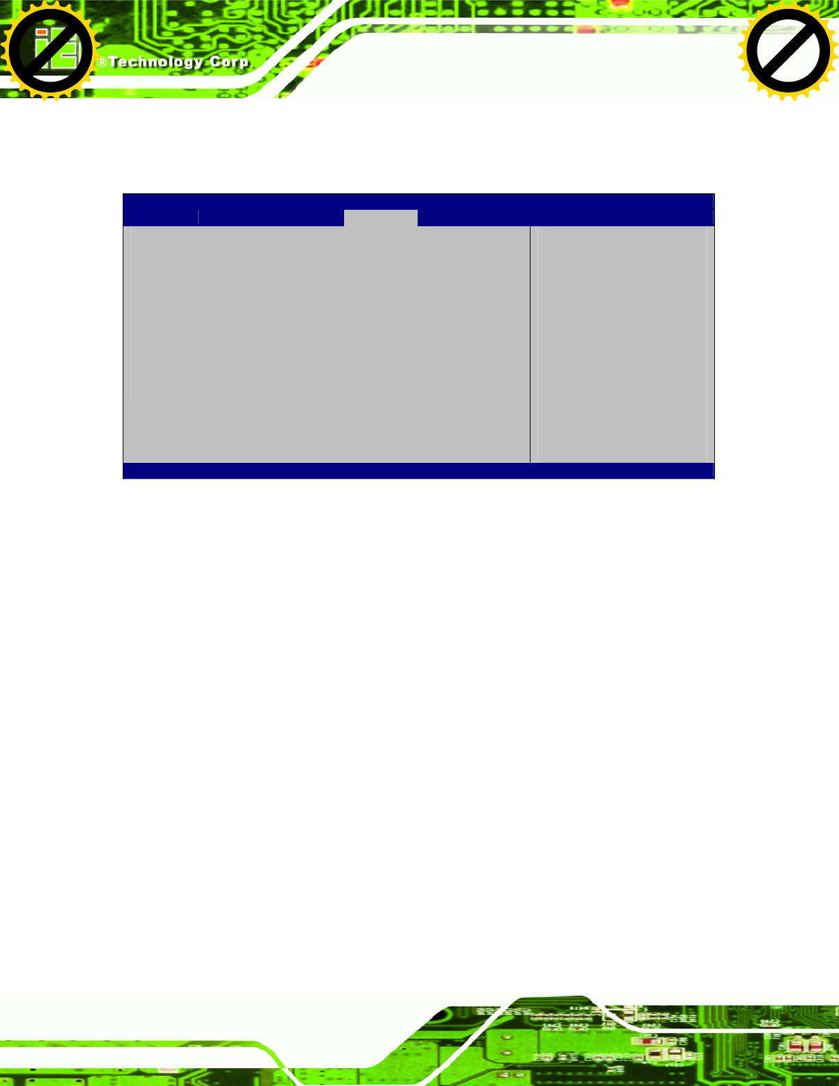
4.3.1 ACPI Settings
The ACPI Settings menu (BIOS Menu 3) configures the Advanced Configuration and
Power Interface (ACPI) options.
Click to buy NOW!
P
D
F
-
X
C
h
a
n
g
e
V
i
e
w
e
r
w
w
w
.
d
o
c
u
-
t
r
a
c
k
.
c
o
m
Click to buy NOW!
P
D
F
-
X
C
h
a
n
g
e
V
i
e
w
e
r
w
w
w
.
d
o
c
u
-
t
r
a
c
k
.
c
o
m
UPC-V312-D525 Panel PC
Page 54
Aptio Setup Utility – Copyright (C) 2010 American Megatrends, Inc.
Advanced
ACPI Sleep State [S1 (CPU Stop Clock)]
Select the highest ACPI
s
leep state the system will
enter, when the SUSPEND
button is pressed.
----------------------
ÅÆ
: Select Screen
↑ ↓: Select Item
Enter Select
F1 General Help
F2 Previous Values
F3 Optimized Defaults
F4 Save
ESC Exit
Version 2.02.1205. Copyright (C) 2010 American Megatrends, Inc.
BIOS Menu 3: ACPI Configuration
Î ACPI Sleep State [S1 (CPU Stop Clock)]
Use the ACPI Sleep State option to specify the sleep state the system enters when it is
not being used.
Î S1 (CPU Stop
Clock)
DEFAULT The system enters S1(POS) sleep state. The
system appears off. The CPU is stopped; RAM is
refreshed; the system is running in a low power
mode.
Î S3 (Suspend to
RAM)
The caches are flushed and the CPU is powered
off. Power to the RAM is maintained. The
computer returns slower to a working state, but
more power is saved.
Click to buy NOW!
P
D
F
-
X
C
h
a
n
g
e
V
i
e
w
e
r
w
w
w
.
d
o
c
u
-
t
r
a
c
k
.
c
o
m
Click to buy NOW!
P
D
F
-
X
C
h
a
n
g
e
V
i
e
w
e
r
w
w
w
.
d
o
c
u
-
t
r
a
c
k
.
c
o
m
UPC-V312-D525 Panel PC
Page 55
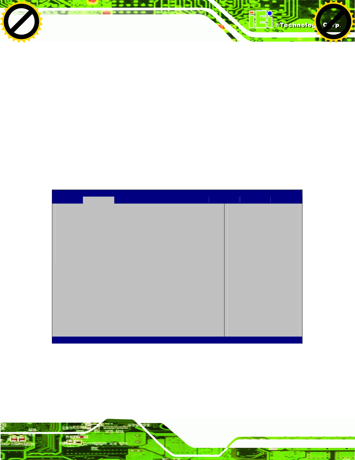
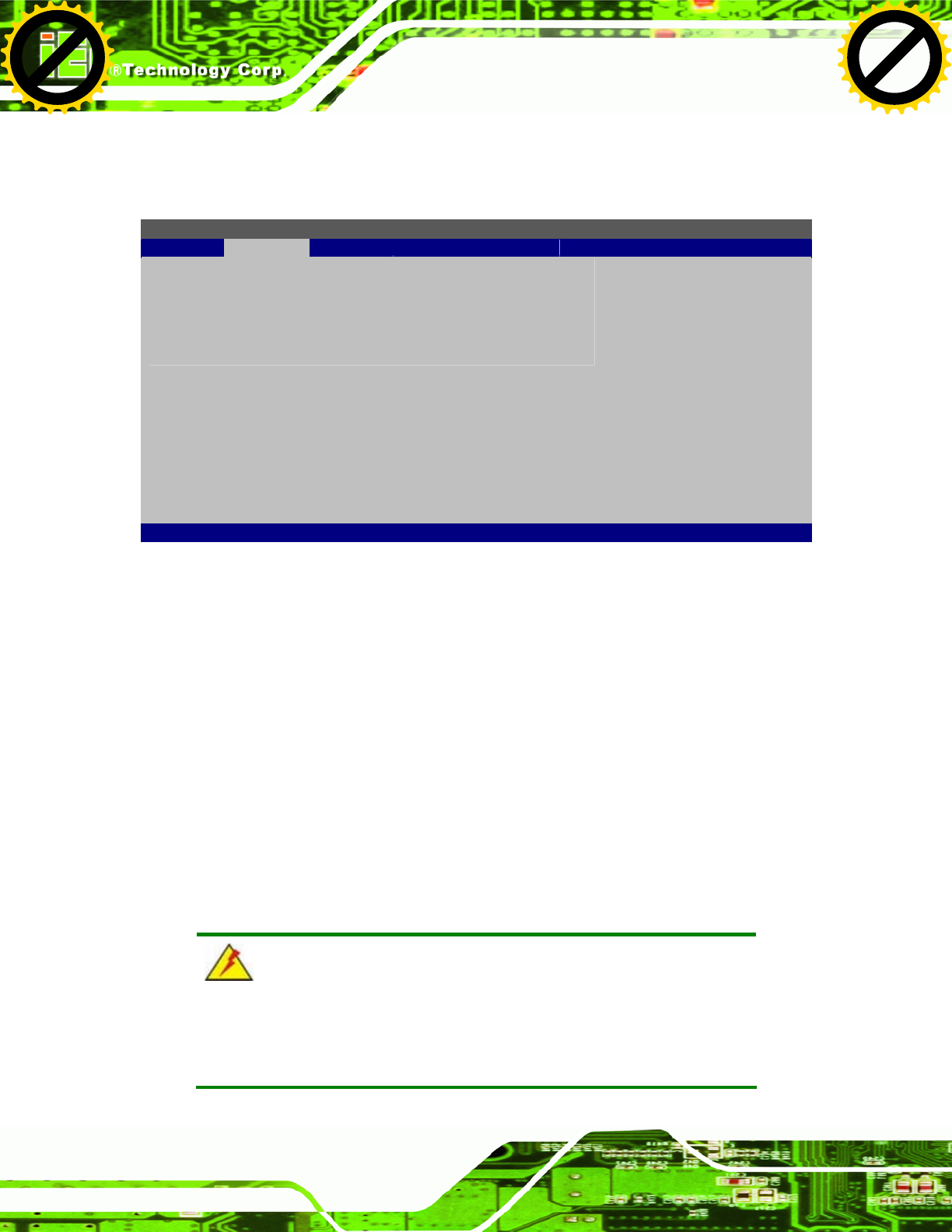
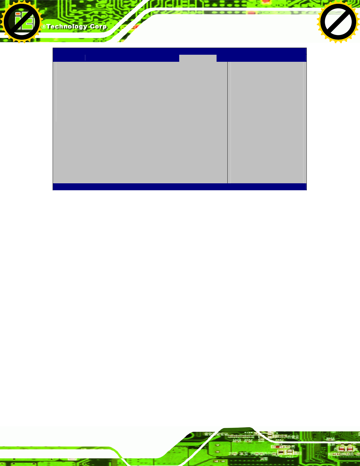
4.3.2 CPU Configuration
Use the CPU Configuration menu (BIOS Menu 4) to view detailed CPU specifications
and configure the CPU.
Aptio Setup Utility – Copyright (C) 2010 American Megatrends, Inc.
Advanced
CPU Configuration
Processor Type Intel(R) Atom(TM)
CPU D525 @ 1.80GHz
EMT64 Supported
Processor Speed 1800 MHz
System Bus Speed 800 MHz
Ratio Status 9
Actual Ratio 9
Processor Stepping 106ca
Microcode Revision 263
L1 Cache RAM 2x56 k
L2 Cache RAM 2x512 k
Processor Cores Dual
Hyper-Threading Supported
Hyper-Threading [Enabled]
----------------------
ÅÆ
: Select Screen
↑ ↓: Select Item
Enter Select
F1 General Help
F2 Previous Values
F3 Optimized Defaults
F4 Save
ESC Exit
Version 2.02.1205. Copyright (C) 2010 American Megatrends, Inc.
BIOS Menu 4: CPU Configuration
The CPU Configuration menu (BIOS Menu 4) lists the following CPU details:
Processor Type: Lists the brand name of the CPU being used
EMT64: Indicates if EM64T is supported by the CPU.
Processor Speed: Lists the CPU processing speed
System Bus Speed: Lists the system bus speed
Ratio Status: Lists the ratio status
Actual Ratio: Lists the actual ratio
Processor Stepping: Lists the CPU processing stepping
Microcode Revision: Lists the microcode revision
L1 Cache RAM: Lists the amount of storage space on the L1 Cache
L2 Cache RAM: Lists the amount of storage space on the L2 Cache
Processor Core: Lists the number of the processor cores
Hyper-Threading: Indicates if Hyper-Threading is supported by the CPU.
Hyper Threading Function [Enabled]
Click to buy NOW!
P
D
F
-
X
C
h
a
n
g
e
V
i
e
w
e
r
w
w
w
.
d
o
c
u
-
t
r
a
c
k
.
c
o
m
Click to buy NOW!
P
D
F
-
X
C
h
a
n
g
e
V
i
e
w
e
r
w
w
w
.
d
o
c
u
-
t
r
a
c
k
.
c
o
m
UPC-V312-D525 Panel PC
Page 56
Use the Hyper Threading function to enable or disable the CPU hyper threading function.
Î Disabled Disables the use of hyper threading technology
Î Enabled DEFAULT Enables the use of hyper threading technology
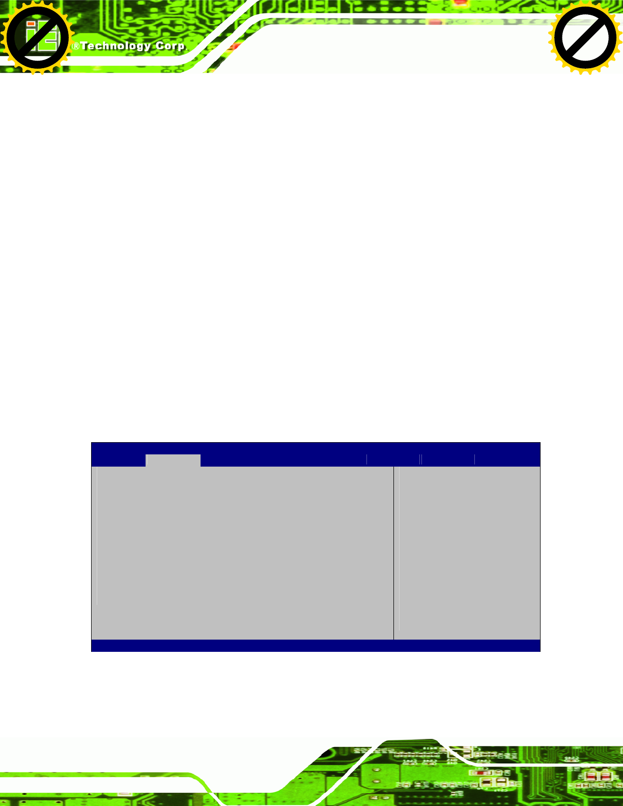
4.3.3 IDE Configuration
Use the IDE Configuration menu (BIOS Menu 5) to change and/or set the configuration
of the IDE or SATA devices installed in the system.
Aptio Setup Utility – Copyright (C) 2010 American Megatrends, Inc.
Advanced
PATA Slave No Present
ATA/IDE Configuration [Compatible]
Legacy IDE Channels [PATA Only]
Select ATA/IDE
Configuration
---------------------
ÅÆ
: Select Screen
↑ ↓: Select Item
Enter Select
F1 General Help
F2 Previous Values
F3 Optimized Defaults
F4 Save
ESC Exit
Version 2.02.1205. Copyright (C) 2010 American Megatrends, Inc.
BIOS Menu 5: IDE Configuration
Î ATA/IDE Configurations [Compatible]
Use the ATA/IDE Configurations option to configure the ATA/IDE controller.
Î Disabled Disables the on-board ATA/IDE controller.
Î Compatible DEFAULT Configures the on-board ATA/IDE controller to be in
compatible mode. In this mode, a SATA channel will
replace one of the IDE channels. This mode supports up
to 4 storage devices.
Click to buy NOW!
P
D
F
-
X
C
h
a
n
g
e
V
i
e
w
e
r
w
w
w
.
d
o
c
u
-
t
r
a
c
k
.
c
o
m
Click to buy NOW!
P
D
F
-
X
C
h
a
n
g
e
V
i
e
w
e
r
w
w
w
.
d
o
c
u
-
t
r
a
c
k
.
c
o
m
UPC-V312-D525 Panel PC
Page 57
Î Enhanced Configures the on-board ATA/IDE controller to be in
Enhanced mode. In this mode, IDE channels and SATA
channels are separated. This mode supports up to 6
storage devices. Some legacy OS do not support this
mode.
Î Legacy IDE Channels [PATA Only]
Î PATA Only Only the PATA drives are enabled.
4.3.4 USB Configuration
Use the USB Configuration menu (BIOS Menu 6) to read USB configuration information
and configure the USB settings.
Aptio Setup Utility – Copyright (C) 2010 American Megatrends, Inc.
Advanced
USB Configuration
USB Devices:
1 Keyboard
Legacy USB Support [Enabled]
Enables Legacy USB
support. AUTO option
d
isables legacy support
if no USB devices are
connected. DISABLE
option will keep USB
devices available only
for EFI applications.
---------------------
ÅÆ
: Select Screen
↑ ↓: Select Item
Enter Select
F1 General Help
F2 Previous Values
F3 Optimized
Defaults
F4 Save
ESC Exit
Version 2.02.1205. Copyright (C) 2010 American Megatrends, Inc.
BIOS Menu 6: USB Configuration
Î USB Devices
The USB Devices Enabled field lists the USB devices that are enabled on the system
Click to buy NOW!
P
D
F
-
X
C
h
a
n
g
e
V
i
e
w
e
r
w
w
w
.
d
o
c
u
-
t
r
a
c
k
.
c
o
m
Click to buy NOW!
P
D
F
-
X
C
h
a
n
g
e
V
i
e
w
e
r
w
w
w
.
d
o
c
u
-
t
r
a
c
k
.
c
o
m
UPC-V312-D525 Panel PC
Page 58
Î Legacy USB Support [Enabled]
Use the Legacy USB Support BIOS option to enable USB mouse and USB keyboard
support. Normally if this option is not enabled, any attached USB mouse or USB keyboard
does not become available until a USB compatible operating system is fully booted with all
USB drivers loaded. When this option is enabled, any attached USB mouse or USB
keyboard can control the system even when there is no USB driver loaded onto the
system.
Î Enabled DEFAULT Legacy USB support enabled
Î Disabled Legacy USB support disabled
Î Auto Legacy USB support disabled if no USB devices are
connected
4.3.5 Super IO Configuration
Use the Super IO Configuration menu (BIOS Menu 7) to set or change the
configurations for the FDD controllers, parallel ports and serial ports.
Aptio Setup Utility – Copyright (C) 2010 American Megatrends, Inc.
Advanced
Super IO Configuration
Super IO Chip Fintek F81865
> Serial Port 1 Configuration
> Serial Port 2 Configuration
> Serial Port 3 Configuration
> Serial Port 4 Configuration
> Serial Port 5 Configuration
> Serial Port 6 Configuration
Set Parameters of Serial
Port 0 (COMA)
---------------------
ÅÆ
: Select Screen
↑ ↓: Select Item
Enter Select
F1 General Help
F2 Previous Values
F3 Optimized Defaults
F4 Save
ESC Exit
Version 2.02.1205. Copyright (C) 2010 American Megatrends, Inc.
BIOS Menu 7: Super IO Configuration
Click to buy NOW!
P
D
F
-
X
C
h
a
n
g
e
V
i
e
w
e
r
w
w
w
.
d
o
c
u
-
t
r
a
c
k
.
c
o
m
Click to buy NOW!
P
D
F
-
X
C
h
a
n
g
e
V
i
e
w
e
r
w
w
w
.
d
o
c
u
-
t
r
a
c
k
.
c
o
m
UPC-V312-D525 Panel PC
Page 59
4.3.5.1 Serial Port n Configuration
Use the Serial Port n Configuration menu (BIOS Menu 8) to configure the serial port n.
Aptio Setup Utility – Copyright (C) 2010 American Megatrends, Inc.
Advanced
Serial Port 1 Configuration
Serial Port [Enabled]
Device Settings IO=3F8h; IRQ=4
Change Settings [Auto]
Enable or Disable Serial
Port (COM)
---------------------
ÅÆ
: Select Screen
↑ ↓: Select Item
Enter Select
F1 General Help
F2 Previous Values
F3 Optimized Defaults
F4 Save
ESC Exit
Version 2.02.1205. Copyright (C) 2010 American Megatrends, Inc.
BIOS Menu 8: Serial Port n Configuration Menu
4.3.5.1.1 Serial Port 1 Configuration
Î Serial Port [Enabled]
Use the Serial Port option to enable or disable the serial port.
Î Disabled Disable the serial port
Î Enabled DEFAULT Enable the serial port
Î Change Settings [Auto]
Use the Change Settings option to change the serial port IO port address and interrupt
address.
Î Auto DEFAULT The serial port IO port address and interrupt address
are automatically detected.
Click to buy NOW!
P
D
F
-
X
C
h
a
n
g
e
V
i
e
w
e
r
w
w
w
.
d
o
c
u
-
t
r
a
c
k
.
c
o
m
Click to buy NOW!
P
D
F
-
X
C
h
a
n
g
e
V
i
e
w
e
r
w
w
w
.
d
o
c
u
-
t
r
a
c
k
.
c
o
m

UPC-V312-D525 Panel PC
Page 60
Î IO=3F8h;
IRQ=4
Serial Port I/O port address is 3F8h and the interrupt
address is IRQ4
Î IO=3F8h;
IRQ=3, 4
Serial Port I/O port address is 3F8h and the interrupt
address is IRQ3, 4
Î IO=2F8h;
IRQ=3, 4
Serial Port I/O port address is 2F8h and the interrupt
address is IRQ3, 4
4.3.5.1.2 Serial Port 2 Configuration
Î Serial Port [Enabled]
Use the Serial Port option to enable or disable the serial port.
Î Disabled Disable the serial port
Î Enabled DEFAULT Enable the serial port
Î Change Settings [Auto]
Use the Change Settings option to change the serial port IO port address and interrupt
address.
Î Auto DEFAULT The serial port IO port address and interrupt address
are automatically detected.
Î IO=2F8h;
IRQ=3
Serial Port I/O port address is 2F8h and the interrupt
address is IRQ3
Î IO=3F8h;
IRQ=3, 4
Serial Port I/O port address is 3F8h and the interrupt
address is IRQ3, 4
Î IO=2F8h;
IRQ=3, 4
Serial Port I/O port address is 2F8h and the interrupt
address is IRQ3, 4
Click to buy NOW!
P
D
F
-
X
C
h
a
n
g
e
V
i
e
w
e
r
w
w
w
.
d
o
c
u
-
t
r
a
c
k
.
c
o
m
Click to buy NOW!
P
D
F
-
X
C
h
a
n
g
e
V
i
e
w
e
r
w
w
w
.
d
o
c
u
-
t
r
a
c
k
.
c
o
m

UPC-V312-D525 Panel PC
Page 61
4.3.5.1.3 Serial Port 3 Configuration
Î Serial Port [Enabled]
Use the Serial Port option to enable or disable the serial port.
Î Disabled Disable the serial port
Î Enabled DEFAULT Enable the serial port
Î Change Settings [Auto]
Use the Change Settings option to change the serial port IO port address and interrupt
address.
Î Auto DEFAULT The serial port IO port address and interrupt address
are automatically detected.
Î IO=3E8h;
IRQ=11
Serial Port I/O port address is 3E8h and the interrupt
address is IRQ11
Î IO=3E8h;
IRQ=10, 11
Serial Port I/O port address is 3E8h and the interrupt
address is IRQ10, 11
Î IO=2E8h;
IRQ=10, 11
Serial Port I/O port address is 2E8h and the interrupt
address is IRQ10, 11
4.3.5.1.4 Serial Port 4 Configuration
Î Serial Port [Enabled]
Use the Serial Port option to enable or disable the serial port.
Î Disabled Disable the serial port
Î Enabled DEFAULT Enable the serial port
Click to buy NOW!
P
D
F
-
X
C
h
a
n
g
e
V
i
e
w
e
r
w
w
w
.
d
o
c
u
-
t
r
a
c
k
.
c
o
m
Click to buy NOW!
P
D
F
-
X
C
h
a
n
g
e
V
i
e
w
e
r
w
w
w
.
d
o
c
u
-
t
r
a
c
k
.
c
o
m

UPC-V312-D525 Panel PC
Page 62
Î Change Settings [Auto]
Use the Change Settings option to change the serial port IO port address and interrupt
address.
Î Auto DEFAULT The serial port IO port address and interrupt address
are automatically detected.
Î IO=2E8h;
IRQ=10
Serial Port I/O port address is 2E8h and the interrupt
address is IRQ10
Î IO=3E8h;
IRQ=10, 11
Serial Port I/O port address is 3E8h and the interrupt
address is IRQ10, 11
Î IO=2E8h;
IRQ=10, 11
Serial Port I/O port address is 2E8h and the interrupt
address is IRQ10, 11
4.3.5.1.5 Serial Port 5 Configuration
Î Serial Port [Enabled]
Use the Serial Port option to enable or disable the serial port.
Î Disabled Disable the serial port
Î Enabled DEFAULT Enable the serial port
Î Change Settings [Auto]
Use the Change Settings option to change the serial port IO port address and interrupt
address.
Î Auto DEFAULT The serial port IO port address and interrupt address
are automatically detected.
Î IO=2E0h;
IRQ=7
Serial Port I/O port address is 2E0h and the interrupt
address is IRQ7
Click to buy NOW!
P
D
F
-
X
C
h
a
n
g
e
V
i
e
w
e
r
w
w
w
.
d
o
c
u
-
t
r
a
c
k
.
c
o
m
Click to buy NOW!
P
D
F
-
X
C
h
a
n
g
e
V
i
e
w
e
r
w
w
w
.
d
o
c
u
-
t
r
a
c
k
.
c
o
m

UPC-V312-D525 Panel PC
Page 63
Î IO=3F8h;
IRQ=3, 4,
5, 6, 7, 10,
11, 12
Serial Port I/O port address is 3F8h and the interrupt
address is IRQ3, 4, 5, 6, 7, 10, 11, 12
Î IO=2F8h;
IRQ=3, 4,
5, 6, 7, 10,
11, 12
Serial Port I/O port address is 2F8h and the interrupt
address is IRQ3, 4, 5, 6, 7, 10, 11, 12
Î IO=3E8h;
IRQ=3, 4,
5, 6, 7, 10,
11, 12
Serial Port I/O port address is 3E8h and the interrupt
address is IRQ3, 4, 5, 6, 7, 10, 11, 12
Î IO=2E8h;
IRQ=3, 4,
5, 6, 7, 10,
11, 12
Serial Port I/O port address is 2E8h and the interrupt
address is IRQ3, 4, 5, 6, 7, 10, 11, 12
Î IO=2E0h;
IRQ=3, 4,
5, 6, 7, 10,
11, 12
Serial Port I/O port address is 2E0h and the interrupt
address is IRQ3, 4, 5, 6, 7, 10, 11, 12
4.3.5.1.6 Serial Port 6 Configuration
Î Serial Port [Enabled]
Use the Serial Port option to enable or disable the serial port.
Î Disabled Disable the serial port
Î Enabled DEFAULT Enable the serial port
Î Change Settings [Auto]
Use the Change Settings option to change the serial port IO port address and interrupt
address.
Click to buy NOW!
P
D
F
-
X
C
h
a
n
g
e
V
i
e
w
e
r
w
w
w
.
d
o
c
u
-
t
r
a
c
k
.
c
o
m
Click to buy NOW!
P
D
F
-
X
C
h
a
n
g
e
V
i
e
w
e
r
w
w
w
.
d
o
c
u
-
t
r
a
c
k
.
c
o
m

UPC-V312-D525 Panel PC
Page 64
Î Auto DEFAULT The serial port IO port address and interrupt address
are automatically detected.
Î IO=2E0h;
IRQ=10
Serial Port I/O port address is 2E0h and the interrupt
address is IRQ10
Î IO=2C0h;
IRQ=10, 11
Serial Port I/O port address is 2C0h and the interrupt
address is IRQ10, 11
Î IO=2C8h;
IRQ=10, 11
Serial Port I/O port address is 2C8h and the interrupt
address is IRQ10, 11
Î IO=2D0h;
IRQ=10, 11
Serial Port I/O port address is 2D0h and the interrupt
address is IRQ10, 11
Î IO=2D8h;
IRQ=10, 11
Serial Port I/O port address is 2D8h and the interrupt
address is IRQ10, 11
Î IO=2E0h;
IRQ=10, 11
Serial Port I/O port address is 2E0h and the interrupt
address is IRQ10, 11
4.3.6 H/W Monitor
The H/W Monitor menu (BIOS Menu 9) shows the operating temperature, fan speeds and
system voltages.
Click to buy NOW!
P
D
F
-
X
C
h
a
n
g
e
V
i
e
w
e
r
w
w
w
.
d
o
c
u
-
t
r
a
c
k
.
c
o
m
Click to buy NOW!
P
D
F
-
X
C
h
a
n
g
e
V
i
e
w
e
r
w
w
w
.
d
o
c
u
-
t
r
a
c
k
.
c
o
m
UPC-V312-D525 Panel PC
Page 65
Aptio Setup Utility – Copyright (C) 2010 American Megatrends, Inc.
Advanced
PC Health Status
CPU Temperature :+50 C
Accuracy: 1.(-5~+10)degree around 100 degree
2.(-10~+15)degree around 50 degree
SYS Temperature :+41 C
VCC3C :+3.360 V
V_core :+1.048 V
Vcc :+4.916 V
Vcc12 :+10.296 V
Vcc1_5VDDR :+1.472 V
VSB3V :+3.376 V
VBAT :+3.232 V
---------------------
ÅÆ
: Select Screen
↑ ↓: Select Item
Enter Select
F1 General Help
F2 Previous Values
F3 Optimized Defaults
F4 Save
ESC Exit
Version 2.02.1205. Copyright (C) 2010 American Megatrends, Inc.
BIOS Menu 9: Hardware Health Configuration
Î PC Health Status
The following system parameters and values are shown. The system parameters that are
monitored are:
System Temperatures:
o CPU Temperature
o System Temperature
Voltages:
o VCC3V
o V_core
o Vcc
o Vcc12
o Vcc1_5VDDR
o VSB3V
o VBAT
4.3.7 Serial Port Console Redirection
The Serial Port Console Redirection menu (BIOS Menu 10) allows the console
redirection options to be configured. Console redirection allows users to maintain a
system remotely by re-directing keyboard input and text output through the serial port.
Click to buy NOW!
P
D
F
-
X
C
h
a
n
g
e
V
i
e
w
e
r
w
w
w
.
d
o
c
u
-
t
r
a
c
k
.
c
o
m
Click to buy NOW!
P
D
F
-
X
C
h
a
n
g
e
V
i
e
w
e
r
w
w
w
.
d
o
c
u
-
t
r
a
c
k
.
c
o
m

UPC-V312-D525 Panel PC
Page 66
Aptio Setup Utility – Copyright (C) 2010 American Megatrends, Inc.
Advanced
COM1
Console Redirection [Enabled]
> Console Redirection Settings
COM3
Console Redirection [Disabled]
> Console Redirection Settings
COM4
Console Redirection [Disabled]
> Console Redirection Settings
Console Redirection
Enable or Disable
---------------------
ÅÆ
: Select Screen
↑ ↓: Select Item
Enter Select
F1 General Help
F2 Previous Values
F3 Optimized Defaults
F4 Save
ESC Exit
Version 2.02.1205. Copyright (C) 2010 American Megatrends, Inc.
BIOS Menu 10: Serial Port Console Redirection
Î Console Redirection [Disabled]
Use Console Redirection option to enable or disable the console redirection function.
Î Disabled DEFAULT Disabled the console redirection function
Î Enabled Enabled the console redirection function
4.3.7.1 Console Redirection Settings
Use the Console Redirection Settings menu (BIOS Menu 11) to configure console
redirection settings of the specified serial port. This menu appears only when the Console
Redirection is enabled.
Click to buy NOW!
P
D
F
-
X
C
h
a
n
g
e
V
i
e
w
e
r
w
w
w
.
d
o
c
u
-
t
r
a
c
k
.
c
o
m
Click to buy NOW!
P
D
F
-
X
C
h
a
n
g
e
V
i
e
w
e
r
w
w
w
.
d
o
c
u
-
t
r
a
c
k
.
c
o
m
UPC-V312-D525 Panel PC
Page 67
Aptio Setup Utility – Copyright (C) 2010 American Megatrends, Inc.
Advanced
COM1
Console Redirection Settings
Terminal Type [ANSI]
Bits per second [115200]
Data Bits [8]
Parity [None]
Stop Bits [1]
Console Redirection
Enable or Disable
---------------------
ÅÆ
: Select Screen
↑ ↓: Select Item
Enter Select
F1 General Help
F2 Previous Values
F3 Optimized Defaults
F4 Save
ESC Exit
Version 2.02.1205. Copyright (C) 2010 American Megatrends, Inc.
BIOS Menu 11: Console Redirection Settings
Î Terminal Type [ANSI]
Use the Terminal Type option to specify the remote terminal type.
Î VT100 The target terminal type is VT100
Î VT100+ The target terminal type is VT100+
Î VT-UTF8 The target terminal type is VT-UTF8
Î ANSI DEFAULT The target terminal type is ANSI
Î Bits per second [115200]
Use the Bits per second option to select serial port transmission speed. The speed must
match on the other side. Long or noisy lines may require lower speeds. The options
include:
9600
19200
57600
115200 DEFAULT
Click to buy NOW!
P
D
F
-
X
C
h
a
n
g
e
V
i
e
w
e
r
w
w
w
.
d
o
c
u
-
t
r
a
c
k
.
c
o
m
Click to buy NOW!
P
D
F
-
X
C
h
a
n
g
e
V
i
e
w
e
r
w
w
w
.
d
o
c
u
-
t
r
a
c
k
.
c
o
m
UPC-V312-D525 Panel PC
Page 68
4.3.8 IEI Feature
Use the IEI Feature menu (BIOS Menu 12) to configure One Key Recovery function.
BIOS SETUP UTILITY
Main Advanced PCIPNP Boot Security Chipset Exit
iEi Feature
⎯⎯⎯⎯⎯⎯⎯⎯⎯⎯⎯⎯⎯⎯⎯⎯⎯⎯⎯⎯⎯⎯⎯⎯⎯⎯⎯⎯⎯⎯⎯
Auto Recovery Function [Disabled]
ÅÆ
Select Screen
↑ ↓ Select Item
Enter Go to SubScreen
F1 General Help
F10 Save and Exit
ESC Exit
v02.61 ©Copyright 1985-2006, American Megatrends, Inc.
BIOS Menu 12: IEI Feature
Î Auto Recovery Function [Disabled]
Use the Auto Recovery Function BIOS option to enable or disable the auto recovery
function of the IEI One Key Recovery.
Î Disabled DEFAULT Auto recovery function disabled
Î Enabled Auto recovery function enabled
4.4 Chipset
Use the Chipset menu (BIOS Menu 13) to access the Northbridge and Southbridge
configuration menus
WARNING!
Setting the wrong values for the Chipset BIOS selections in the Chipset
BIOS menu may cause the system to malfunction.
Click to buy NOW!
P
D
F
-
X
C
h
a
n
g
e
V
i
e
w
e
r
w
w
w
.
d
o
c
u
-
t
r
a
c
k
.
c
o
m
Click to buy NOW!
P
D
F
-
X
C
h
a
n
g
e
V
i
e
w
e
r
w
w
w
.
d
o
c
u
-
t
r
a
c
k
.
c
o
m
UPC-V312-D525 Panel PC
Page 69
Aptio Setup Utility – Copyright (C) 2010 American Megatrends, Inc.
Main Advanced Chipset Boot Save & Exit
> Host Bridge
> South Bridge
> Intel IGD SWSCI OpRegion
Host Bridge Parameters
---------------------
ÅÆ
: Select Screen
↑ ↓: Select Item
Enter Select
F1 General Help
F2 Previous Values
F3 Optimized Defaults
F4 Save
ESC Exit
Version 2.02.1205. Copyright (C) 2010 American Megatrends, Inc.
BIOS Menu 13: Chipset
4.4.1 Host Bridge Configuration
Use the Host Bridge Configuration menu (BIOS Menu 14) to configure the Northbridge
chipset.
Aptio Setup Utility – Copyright (C) 2010 American Megatrends, Inc.
Chipset
******* Memory Information *******
Memory Frequency 800 Mhz
Total Memory 1024 MB
DIMM#0 1024 MB
DIMM#1 Not Present
---------------------
ÅÆ
: Select Screen
↑ ↓: Select Item
Enter Select
F1 General Help
F2 Previous Values
F3 Optimized Defaults
F4 Save
ESC Exit
Version 2.02.1205. Copyright (C) 2010 American Megatrends, Inc.
BIOS Menu 14: Host Bridge Chipset Configuration
Click to buy NOW!
P
D
F
-
X
C
h
a
n
g
e
V
i
e
w
e
r
w
w
w
.
d
o
c
u
-
t
r
a
c
k
.
c
o
m
Click to buy NOW!
P
D
F
-
X
C
h
a
n
g
e
V
i
e
w
e
r
w
w
w
.
d
o
c
u
-
t
r
a
c
k
.
c
o
m
UPC-V312-D525 Panel PC
Page 70
4.4.2 South Bridge Configuration
Use the South Bbridge Configuration menu (BIOS Menu 15) to configure the
Southbridge chipset.
Aptio Setup Utility – Copyright (C) 2010 American Megatrends, Inc.
Chipset
Auto Power Button Function [Enabled]
High Definition Audio Controller [Enabled]
USB Function [Enabled]
USB 2.0(EHCI) Support [Enabled]
Set Spread Spectrum function [Disabled]
WIFI Support [Enabled]
GPS Support [Disabled]
MIC Support [Enabled]
Auto Dimming Support [Enabled]
High Definition Audio
Controller
---------------------
ÅÆ
: Select Screen
↑ ↓: Select Item
Enter Select
F1 General Help
F2 Previous Values
F3 Optimized Defaults
F4 Save
ESC Exit
Version 2.02.1205. Copyright (C) 2010 American Megatrends, Inc.
BIOS Menu 15: South Bridge Chipset Configuration
Î High Definition Audio Controller [Enabled]
The High Definition Audio Controller option enables or disables the HD Audio
controller.
Î Enabled DEFAULT The onboard HD Audio controller is enabled
Î Disabled The onboard HD Audio controller is disabled
Î USB Function [Enabled]
Use the USB Function BIOS option to enable or disable USB function support.
Î Disabled USB function support disabled
Î Enabled DEFAULT USB function support enabled
Click to buy NOW!
P
D
F
-
X
C
h
a
n
g
e
V
i
e
w
e
r
w
w
w
.
d
o
c
u
-
t
r
a
c
k
.
c
o
m
Click to buy NOW!
P
D
F
-
X
C
h
a
n
g
e
V
i
e
w
e
r
w
w
w
.
d
o
c
u
-
t
r
a
c
k
.
c
o
m

UPC-V312-D525 Panel PC
Page 71
Î Set Spread Spectrum function [Disabled]
Use the Set Spread Spectrum function option to reduce the EMI. Excess EMI is
generated when the system clock generator pulses have extreme values. Spreading the
pulse spectrum modulates changes in the extreme values from spikes to flat curves, thus
reducing the EMI. This benefit may in some cases be outweighed by problems with
timing-critical devices, such as a clock-sensitive SCSI device.
Î Disabled DEFAULT EMI not reduced
Î Enabled EMI reduced
Î WIFI Support [Enabled]
Use the WIFI Support option to enable or disable the Wi-Fi function.
Î Enabled DEFAULT Enables Wi-Fi function
Î Disabled Disables Wi-Fi function
Î GPS Support [Disabled]
Use the GPS Support option to enable or disable the GPS function.
Î Enabled Enables GPS function
Î Disabled DEFAULT Disables GPS function
Î MIC Support [Enabled]
Use the MIC Support option to enable or disable the microphone.
Î Enabled DEFAULT Enables microphone
Î Disabled Disables microphone
Î Auto Dimming Support [Enabled]
Use the Auto Dimming Support option to enable or disable the auto dimming function.
Î Enabled DEFAULT Enables auto dimming function
Click to buy NOW!
P
D
F
-
X
C
h
a
n
g
e
V
i
e
w
e
r
w
w
w
.
d
o
c
u
-
t
r
a
c
k
.
c
o
m
Click to buy NOW!
P
D
F
-
X
C
h
a
n
g
e
V
i
e
w
e
r
w
w
w
.
d
o
c
u
-
t
r
a
c
k
.
c
o
m

UPC-V312-D525 Panel PC
Page 72
Î Disabled Disables auto dimming function
4.4.3 Intel IGD SWSCI OpRegion
Use the Intel IGD SWSCI OpRegion menu (BIOS Menu 16) to configure the video device
connected to the system.
Aptio Setup Utility – Copyright (C) 2010 American Megatrends, Inc.
Advanced
Intel IGD SWSCI OpRegion Configuration
DVMT Mode Select [DVMT Mode]
DVMT/FIXED Memory [Maximum]
IGD - Boot Type [VBIOS Default]
LCD Panel Type [1024x768 18bit]
Backlight Control [Inverted]
Select DVMT Mode/Fixed
Mode
---------------------
ÅÆ
: Select Screen
↑ ↓: Select Item
Enter Select
+/-: Change Opt.
F1 General Help
F2 Previous Values
F3 Optimized Defaults
F4 Save
ESC Exit
Version 2.02.1205. Copyright (C) 2010 American Megatrends, Inc.
BIOS Menu 16: Intel IGD SWSCI OpRegion
Î DVMT Mode Select [DVMT Mode]
Use the DVMT Mode Select option to select the Intel Dynamic Video Memory Technology
(DVMT) operating mode.
Î Fixed Mode A fixed portion of graphics memory is reserved as
graphics memory.
Î DVMT Mode DEFAULT Graphics memory is dynamically allocated according to
the system and graphics needs.
Î DVMT/FIXED Memory [Maximum]
Use the DVMT/FIXED Memory option to specify the maximum amount of memory that
can be allocated as graphics memory. Configuration options are listed below.
128 MB
Click to buy NOW!
P
D
F
-
X
C
h
a
n
g
e
V
i
e
w
e
r
w
w
w
.
d
o
c
u
-
t
r
a
c
k
.
c
o
m
Click to buy NOW!
P
D
F
-
X
C
h
a
n
g
e
V
i
e
w
e
r
w
w
w
.
d
o
c
u
-
t
r
a
c
k
.
c
o
m

UPC-V312-D525 Panel PC
Page 73
256 MB
Maximum Default
Î IGD - Boot Type [VBIOS Default]
Use the IGD - Boot Type option to select the display device used by the system when it
boots. Configuration options are listed below.
VBIOS Default DEFAULT
CRT
LFP
CRT + LFP
Î LCD Panel Type [1024x768 18bit]
Use the LCD Panel Type option to select the type of flat panel connected to the system.
Configuration option is listed below.
1024x768 18bit DEFAULT
DVMT Mode Select [DVMT Mode]
Î Backlight Control [Inverted]
Use the Backlight Control option to select the backlight control mode.
Î Normal Brightest at high voltage level
Î Inverted DEFAULT Brightest at low voltage level
Click to buy NOW!
P
D
F
-
X
C
h
a
n
g
e
V
i
e
w
e
r
w
w
w
.
d
o
c
u
-
t
r
a
c
k
.
c
o
m
Click to buy NOW!
P
D
F
-
X
C
h
a
n
g
e
V
i
e
w
e
r
w
w
w
.
d
o
c
u
-
t
r
a
c
k
.
c
o
m
UPC-V312-D525 Panel PC
Page 74
4.5 Boot
Use the Boot menu (BIOS Menu 17) to configure system boot options.
Aptio Setup Utility – Copyright (C) 2010 American Megatrends, Inc.
Main Advanced Chipset Boot Save & Exit
Boot Configuration
Bootup NumLock State [On]
Quiet Boot [Enabled]
Launch PXE OpROM [Disabled]
Boot Option Priorities
Boot Option #1 [PATA: IEI Technolo..]
Hard Drive BBS Priorities
Select the keyboard
NumLock state
---------------------
ÅÆ
: Select Screen
↑ ↓: Select Item
Enter Select
F1 General Help
F2 Previous Values
F3 Optimized
Defaults
F4 Save
ESC Exit
Version 2.02.1205. Copyright (C) 2010 American Megatrends, Inc.
BIOS Menu 17: Boot
Î Bootup NumLock State [On]
Use the Bootup NumLock State BIOS option to specify if the number lock setting must
be modified during boot up.
Î On DEFAULT Allows the Number Lock on the keyboard to be
enabled automatically when the computer system
boots up. This allows the immediate use of the
10-key numeric keypad located on the right side of
the keyboard. To confirm this, the Number Lock LED
light on the keyboard is lit.
Î Off Does not enable the keyboard Number Lock
automatically. To use the 10-keys on the keyboard,
press the Number Lock key located on the upper
left-hand corner of the 10-key pad. The Number
Lock LED on the keyboard lights up when the
Number Lock is engaged.
Click to buy NOW!
P
D
F
-
X
C
h
a
n
g
e
V
i
e
w
e
r
w
w
w
.
d
o
c
u
-
t
r
a
c
k
.
c
o
m
Click to buy NOW!
P
D
F
-
X
C
h
a
n
g
e
V
i
e
w
e
r
w
w
w
.
d
o
c
u
-
t
r
a
c
k
.
c
o
m

UPC-V312-D525 Panel PC
Page 75
Î Quiet Boot [Enabled]
Use the Quiet Boot BIOS option to select the screen display when the system boots.
Î Disabled Normal POST messages displayed
Î Enabled DEFAULT OEM Logo displayed instead of POST messages
Î Launch PXE OpROM [Disabled]
Use the Launch PXE OpROM option to enable or disable boot option for legacy network
devices.
Î Disabled DEFAULT Ignore all PXE Option ROMs
Î Enabled Load PXE Option ROMs
Î Boot Option #1 [PATA: IEI Technology Corp. ICF]
Use the Boot Option #1 option to specify the boot sequence from the available devices.
4.6 Save & Exit
Use the Save & Exit menu (BIOS Menu 18) to load default BIOS values, optimal failsafe
values and to save configuration changes.
Click to buy NOW!
P
D
F
-
X
C
h
a
n
g
e
V
i
e
w
e
r
w
w
w
.
d
o
c
u
-
t
r
a
c
k
.
c
o
m
Click to buy NOW!
P
D
F
-
X
C
h
a
n
g
e
V
i
e
w
e
r
w
w
w
.
d
o
c
u
-
t
r
a
c
k
.
c
o
m
UPC-V312-D525 Panel PC
Page 76
Aptio Setup Utility – Copyright (C) 2010 American Megatrends, Inc.
Main Advanced Chipset Boot Save & Exit
Save Changes and Reset
Discard Changes and Reset
Restore Defaults
Save as User Defaults
Restore User Defaults
E
xit system setup after
saving the changes.
---------------------
ÅÆ
: Select Screen
↑ ↓: Select Item
Enter Select
F1 General Help
F2 Previous Values
F3 Optimized
Defaults
F4 Save
ESC Exit
Version 2.02.1205. Copyright (C) 2010 American Megatrends, Inc.
BIOS Menu 18: Save & Exit
Î Save Changes and Reset
Use the Save Changes and Reset option to save the changes made to the BIOS options
and reset the system.
Î Discard Changes and Reset
Use the Discard Changes and Reset option to exit the system without saving the
changes made to the BIOS configuration setup program.
Î Restore Defaults
Use the Restore Defaults option to load the optimal default values for each of the
parameters on the Setup menus. F3 key can be used for this operation.
Î Save as User Defaults
Use the Save as User Defaults option to save the changes done so far as user defaults.
Î Restore User Defaults
Use the Restore User Defaults option to restore the user defaults to all the setup options.
Click to buy NOW!
P
D
F
-
X
C
h
a
n
g
e
V
i
e
w
e
r
w
w
w
.
d
o
c
u
-
t
r
a
c
k
.
c
o
m
Click to buy NOW!
P
D
F
-
X
C
h
a
n
g
e
V
i
e
w
e
r
w
w
w
.
d
o
c
u
-
t
r
a
c
k
.
c
o
m


UPC-V312-D525 Panel PC
Page 79
5.1 Available Software Drivers
NOTE:
The content of the CD may vary throughout the life cycle of the product
and is subject to change without prior notice. Visit the IEI website or
contact technical support for the latest updates.
The following drivers can be installed on the system:
Chipset
Graphic
LAN
Audio
Touch Screen
GPS
CAN-bus interface
Installation instructions are given below.
5.2 Starting the Driver Program
To access the driver installation programs, please do the following.
Step 1: Insert the CD-ROM that came with the system into a CD-ROM drive attached to
the system.
Step 2: Click UPC-V312-D525.
Step 3: A list of available drivers appears.Step 0:
Click to buy NOW!
P
D
F
-
X
C
h
a
n
g
e
V
i
e
w
e
r
w
w
w
.
d
o
c
u
-
t
r
a
c
k
.
c
o
m
Click to buy NOW!
P
D
F
-
X
C
h
a
n
g
e
V
i
e
w
e
r
w
w
w
.
d
o
c
u
-
t
r
a
c
k
.
c
o
m
UPC-V312-D525 Panel PC
Page 80
5.3 Chipset Driver Installation
To install the chipset driver, please do the following.
Step 1: Access the driver list. (See Section 5.2)
Step 2: Click “Chipset” and select the folder which corresponds to the operating system.
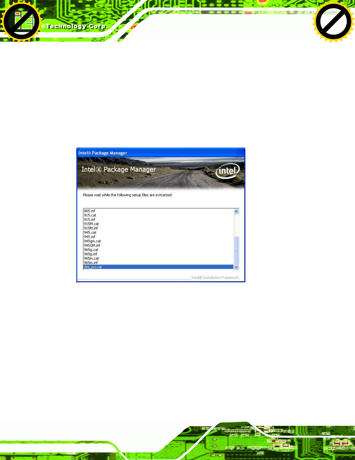
Step 3: Locate the setup file and double click on it.
Step 4: The setup files are extracted as shown in Figure 5-1.
Figure 5-1: Chipset Driver Screen
Step 5: When the setup files are completely extracted the Welcome Screen in Figure
5-2 appears.
Step 6: Click Next to continue.
Click to buy NOW!
P
D
F
-
X
C
h
a
n
g
e
V
i
e
w
e
r
w
w
w
.
d
o
c
u
-
t
r
a
c
k
.
c
o
m
Click to buy NOW!
P
D
F
-
X
C
h
a
n
g
e
V
i
e
w
e
r
w
w
w
.
d
o
c
u
-
t
r
a
c
k
.
c
o
m

UPC-V312-D525 Panel PC
Page 81
Figure 5-2: Chipset Driver Welcome Screen
Step 7: The license agreement in Figure 5-3 appears.
Step 8: Read the License Agreement.
Step 9: Click Yes to continue.
Figure 5-3: Chipset Driver License Agreement
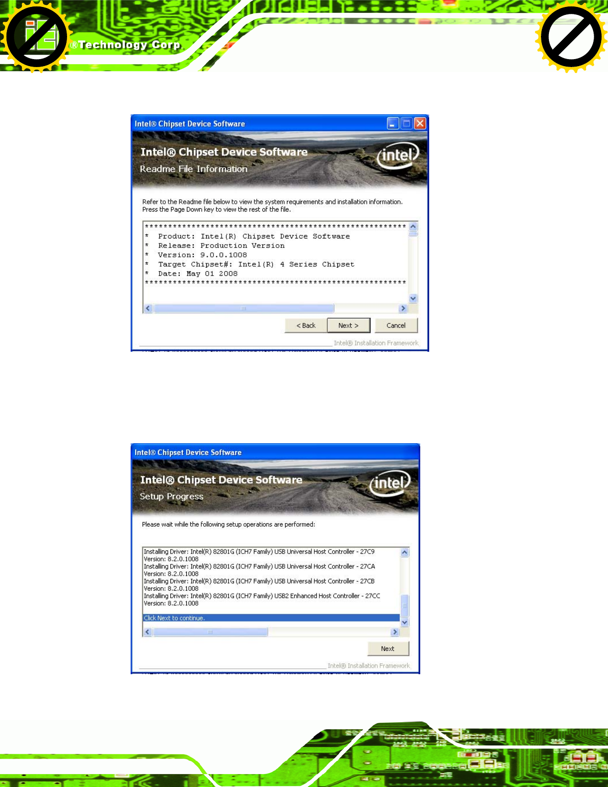
Step 10: The Read Me file in Figure 5-4 appears.
Click to buy NOW!
P
D
F
-
X
C
h
a
n
g
e
V
i
e
w
e
r
w
w
w
.
d
o
c
u
-
t
r
a
c
k
.
c
o
m
Click to buy NOW!
P
D
F
-
X
C
h
a
n
g
e
V
i
e
w
e
r
w
w
w
.
d
o
c
u
-
t
r
a
c
k
.
c
o
m
UPC-V312-D525 Panel PC
Page 82
Step 11: Click Next to continue.
Figure 5-4: Chipset Driver Read Me File
Step 12: Setup Operations are performed as shown in Figure 5-5.
Step 13: Once the Setup Operations are complete, click Next to continue.
Figure 5-5: Chipset Driver Setup Operations
Click to buy NOW!
P
D
F
-
X
C
h
a
n
g
e
V
i
e
w
e
r
w
w
w
.
d
o
c
u
-
t
r
a
c
k
.
c
o
m
Click to buy NOW!
P
D
F
-
X
C
h
a
n
g
e
V
i
e
w
e
r
w
w
w
.
d
o
c
u
-
t
r
a
c
k
.
c
o
m
UPC-V312-D525 Panel PC
Page 83
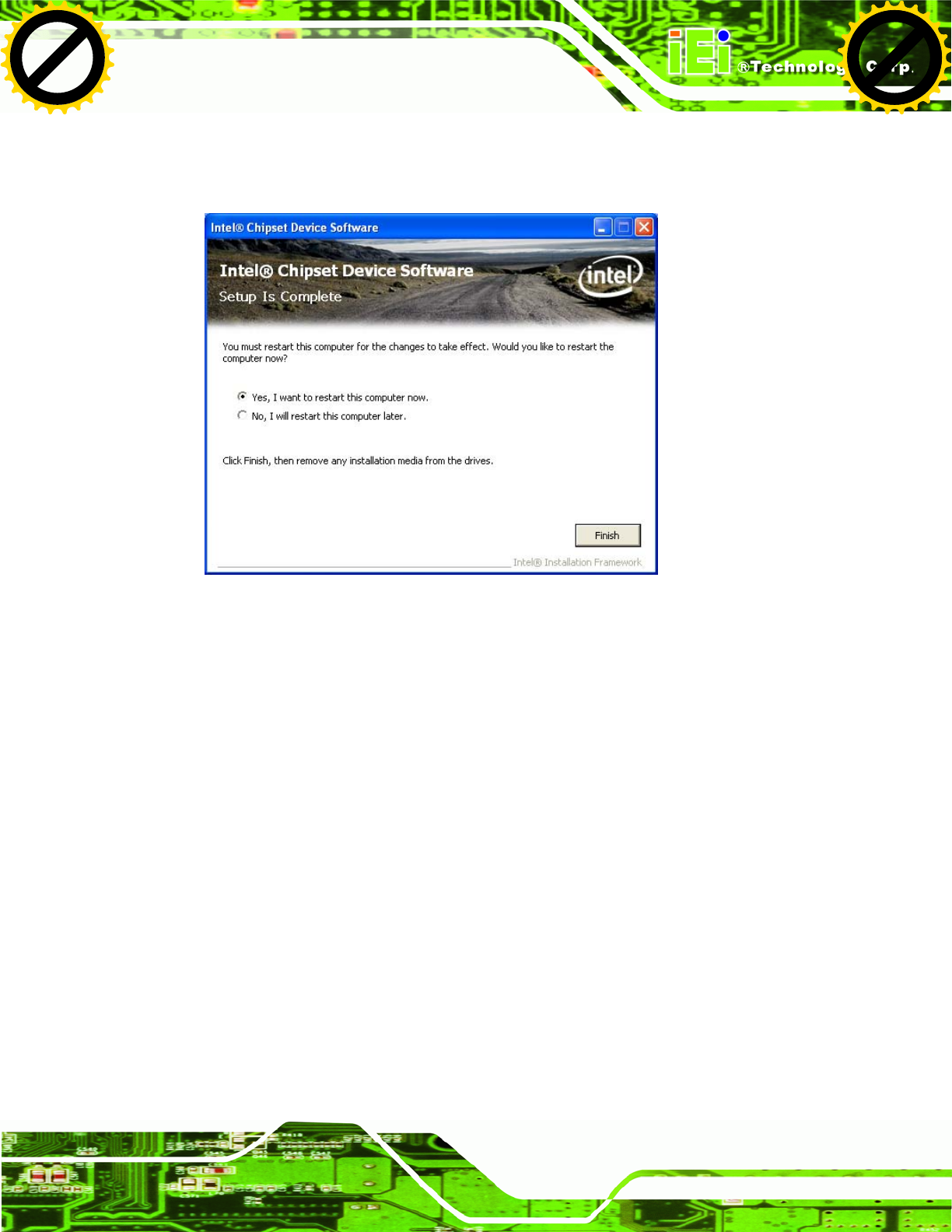
Step 14: The Finish screen in Figure 5-6 appears.
Step 15: Select “Yes, I want to restart this computer now” and click Finish.Step 0:
Figure 5-6: Chipset Driver Installation Finish Screen
5.4 Graphics Driver Installation
To install the Graphics driver, please do the following.
Step 1: Access the driver list. (See Section 5.2)
Step 2: Click “Graphic” and select the folder which corresponds to the operating
system.
Step 3: Double click the setup file.
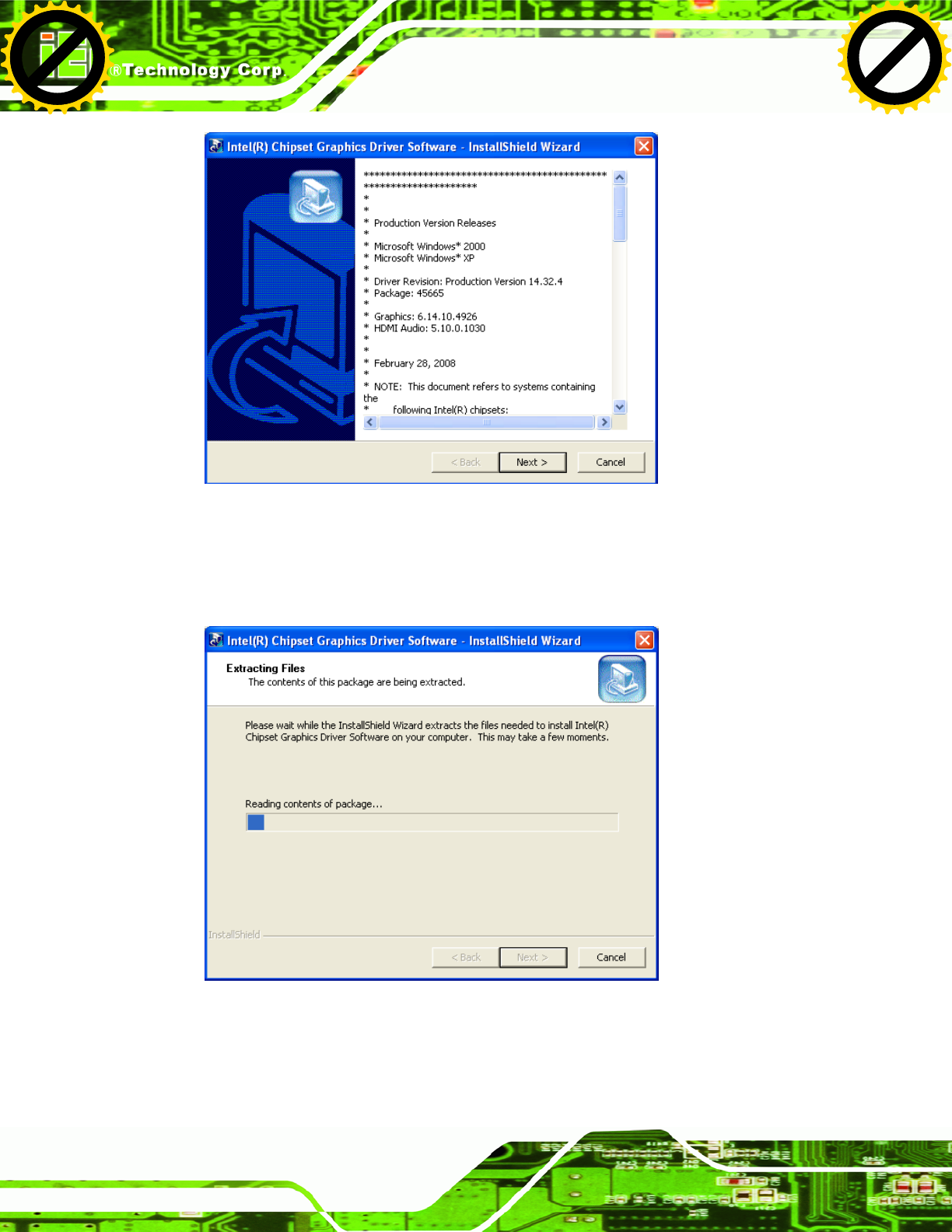
Step 4: The Read Me file in Figure 5-7 appears.
Step 5: Click Next to continue.
Click to buy NOW!
P
D
F
-
X
C
h
a
n
g
e
V
i
e
w
e
r
w
w
w
.
d
o
c
u
-
t
r
a
c
k
.
c
o
m
Click to buy NOW!
P
D
F
-
X
C
h
a
n
g
e
V
i
e
w
e
r
w
w
w
.
d
o
c
u
-
t
r
a
c
k
.
c
o
m
UPC-V312-D525 Panel PC
Page 84
Figure 5-7: Graphics Driver Read Me File
Step 6: The installation files are extracted. See Figure 5-8.
Step 7: Click Next to continue.
Figure 5-8: Graphics Driver Setup Files Extracted
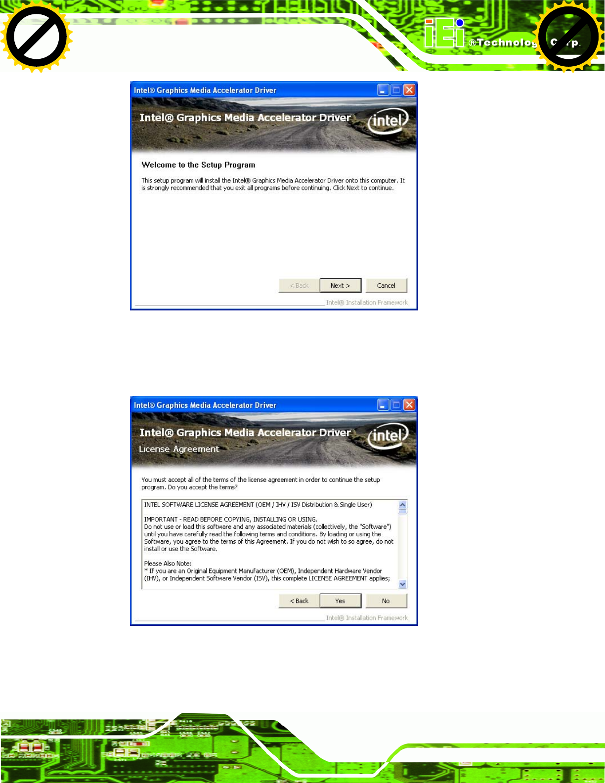
Step 8: The Welcome Screen in Figure 5-9 appears.
Step 9: Click Next to continue.
Click to buy NOW!
P
D
F
-
X
C
h
a
n
g
e
V
i
e
w
e
r
w
w
w
.
d
o
c
u
-
t
r
a
c
k
.
c
o
m
Click to buy NOW!
P
D
F
-
X
C
h
a
n
g
e
V
i
e
w
e
r
w
w
w
.
d
o
c
u
-
t
r
a
c
k
.
c
o
m
UPC-V312-D525 Panel PC
Page 85
Figure 5-9: Graphics Driver Welcome Screen
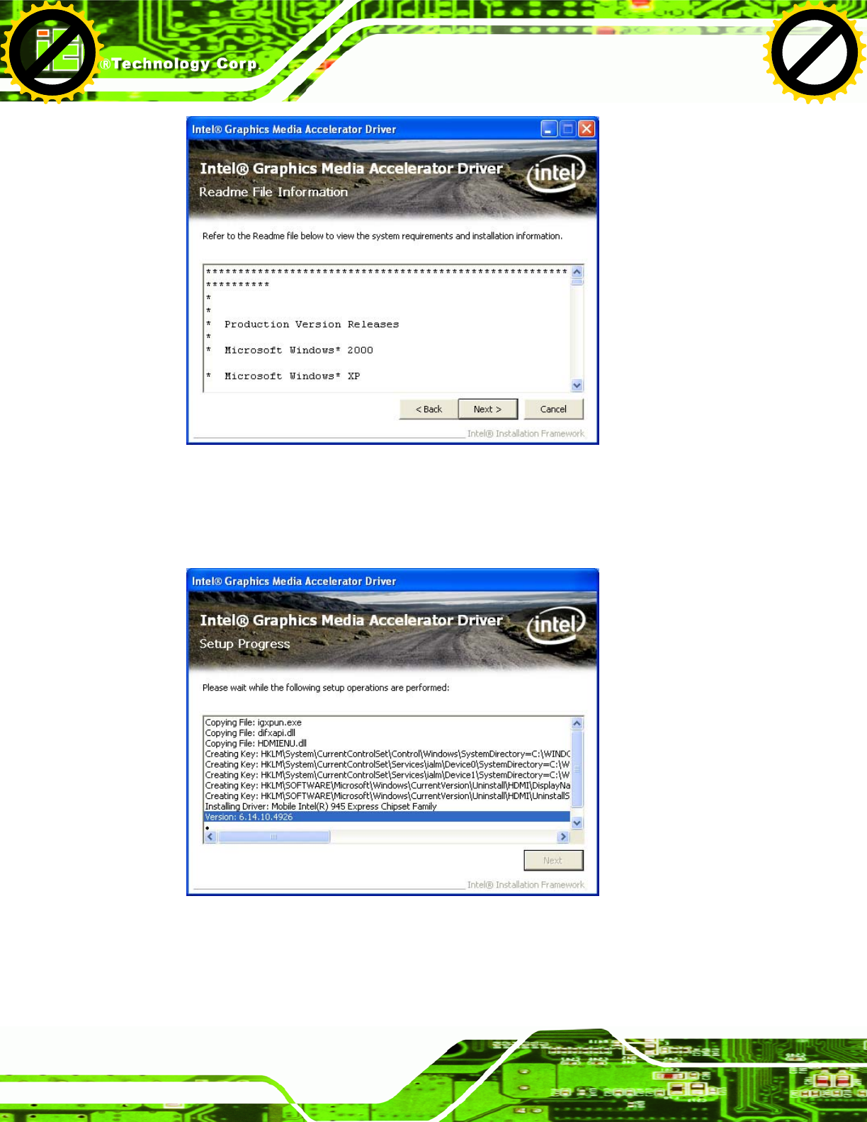
Step 10: The License Agreement in Figure 5-10 appears.
Step 11: Click Yes to accept the agreement and continue.
Figure 5-10: Graphics Driver License Agreement
Step 12: The Read Me file in Figure 5-11 appears.
Step 13: Click Next to continue.
Click to buy NOW!
P
D
F
-
X
C
h
a
n
g
e
V
i
e
w
e
r
w
w
w
.
d
o
c
u
-
t
r
a
c
k
.
c
o
m
Click to buy NOW!
P
D
F
-
X
C
h
a
n
g
e
V
i
e
w
e
r
w
w
w
.
d
o
c
u
-
t
r
a
c
k
.
c
o
m
UPC-V312-D525 Panel PC
Page 86
Figure 5-11: Graphics Driver Read Me File
Step 14: Setup Operations are performed as shown in Figure 5-12.
Step 15: Once the Setup Operations are complete, click Next to continue.
Figure 5-12: Graphics Driver Setup Operations
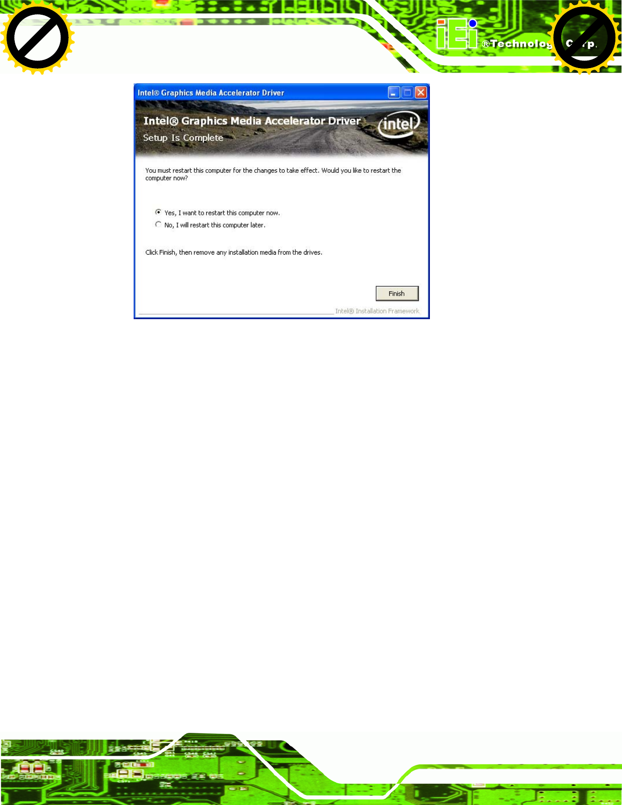
Step 16: The Finish screen in Figure 5-13 appears.
Step 17: Select “Yes, I want to restart this computer now” and click Finish.Step 0:
Click to buy NOW!
P
D
F
-
X
C
h
a
n
g
e
V
i
e
w
e
r
w
w
w
.
d
o
c
u
-
t
r
a
c
k
.
c
o
m
Click to buy NOW!
P
D
F
-
X
C
h
a
n
g
e
V
i
e
w
e
r
w
w
w
.
d
o
c
u
-
t
r
a
c
k
.
c
o
m
UPC-V312-D525 Panel PC
Page 87
Figure 5-13: Graphics Driver Installation Finish Screen
5.5 LAN Driver Installation
To install the LAN driver, please do the following.
Step 1: Access the driver list. (See Section 5.2)
Step 2: Click “LAN” and select the Realtek folder
Step 3: Select the folder which corresponds to the operating system.
Step 4: Double click the setup file.
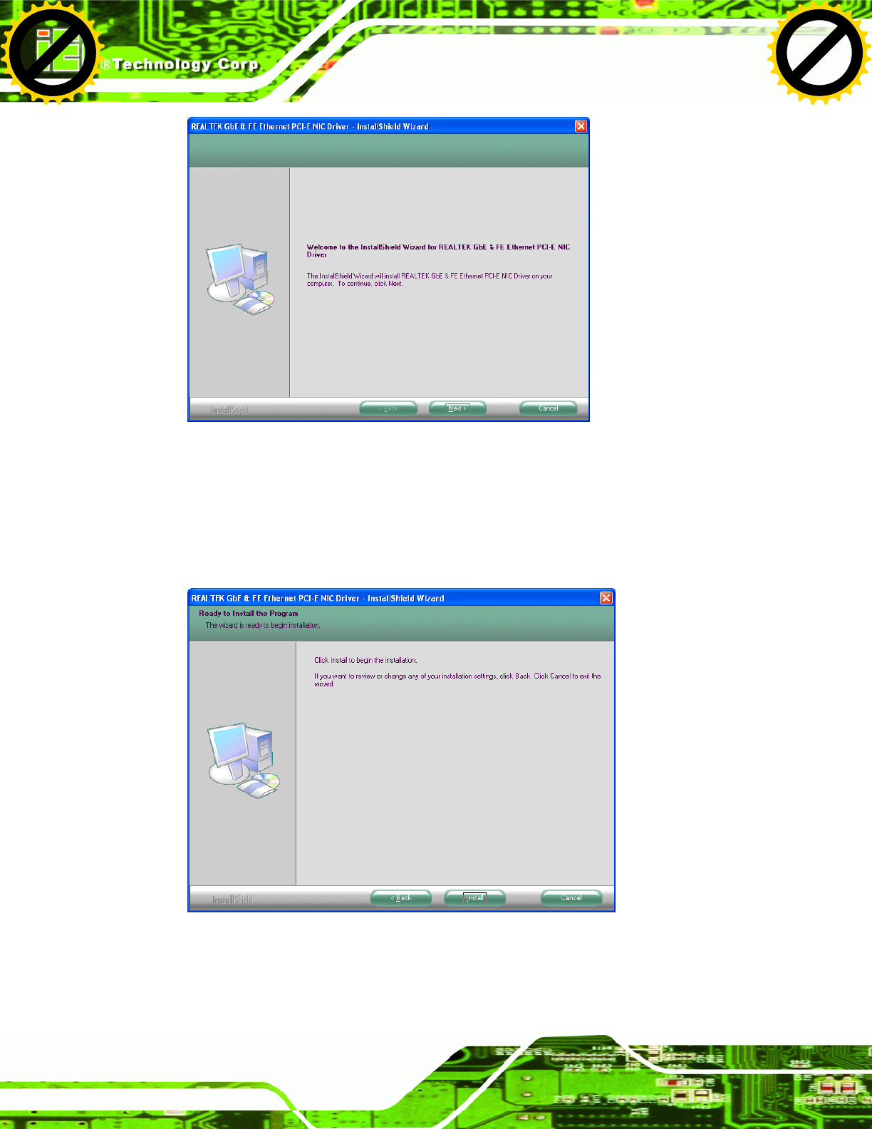
Step 5: The Welcome screen in Figure 5-31 appears.
Click to buy NOW!
P
D
F
-
X
C
h
a
n
g
e
V
i
e
w
e
r
w
w
w
.
d
o
c
u
-
t
r
a
c
k
.
c
o
m
Click to buy NOW!
P
D
F
-
X
C
h
a
n
g
e
V
i
e
w
e
r
w
w
w
.
d
o
c
u
-
t
r
a
c
k
.
c
o
m
UPC-V312-D525 Panel PC
Page 88
Figure 5-14: LAN Driver Welcome Screen
Step 6: Click Next to continue.
Step 7: The Ready to Install screen in Figure 5-15 appears.
Step 8: Click Next to proceed with the installation.
Figure 5-15: LAN Driver Welcome Screen
Step 9: The program begins to install.
Click to buy NOW!
P
D
F
-
X
C
h
a
n
g
e
V
i
e
w
e
r
w
w
w
.
d
o
c
u
-
t
r
a
c
k
.
c
o
m
Click to buy NOW!
P
D
F
-
X
C
h
a
n
g
e
V
i
e
w
e
r
w
w
w
.
d
o
c
u
-
t
r
a
c
k
.
c
o
m
UPC-V312-D525 Panel PC
Page 89
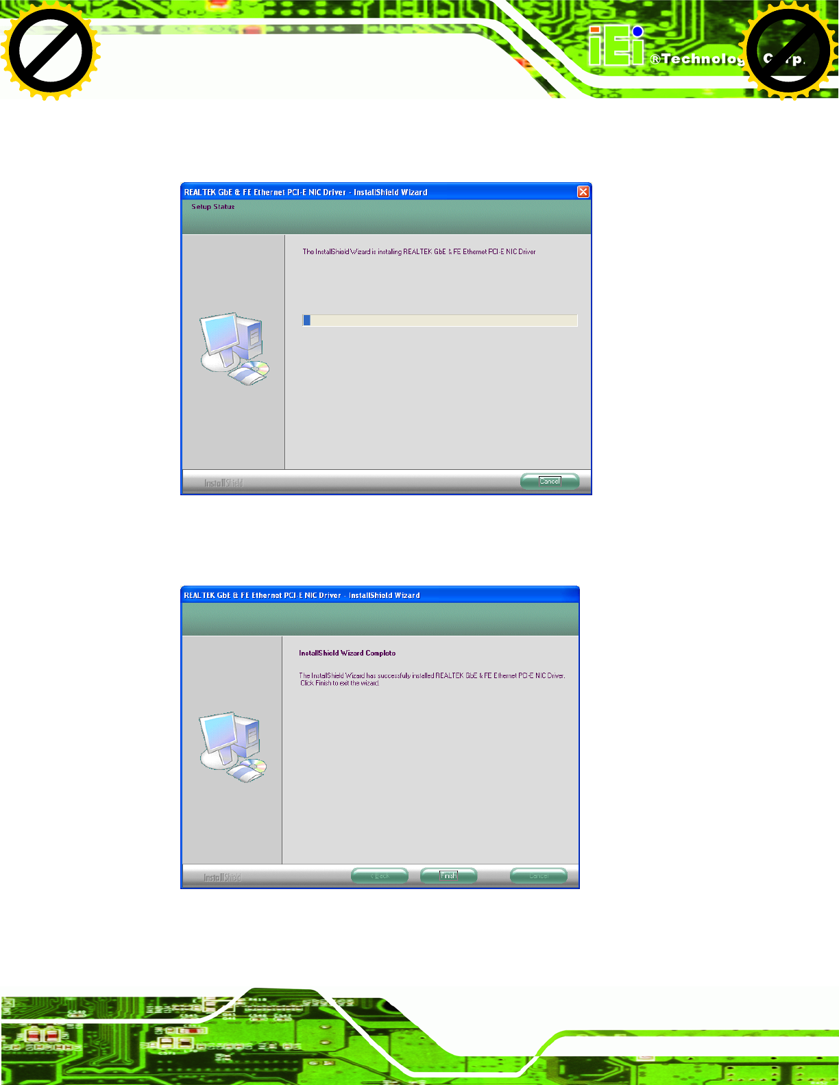
Step 10: The installation progress can be monitored in the progress bar shown in Figure
5-16.
Figure 5-16: LAN Driver Installation
Step 11: When the driver installation is complete, the screen in Figure 5-17 appears.
Figure 5-17: LAN Driver Installation Complete
Click to buy NOW!
P
D
F
-
X
C
h
a
n
g
e
V
i
e
w
e
r
w
w
w
.
d
o
c
u
-
t
r
a
c
k
.
c
o
m
Click to buy NOW!
P
D
F
-
X
C
h
a
n
g
e
V
i
e
w
e
r
w
w
w
.
d
o
c
u
-
t
r
a
c
k
.
c
o
m
UPC-V312-D525 Panel PC
Page 90
5.6 Audio Driver Installation
To install the audio driver, please do the following.
Step 1: Access the driver list. (See Section 5.2)
Step 2: Click “Audio”.
Step 3: Double click the setup file.
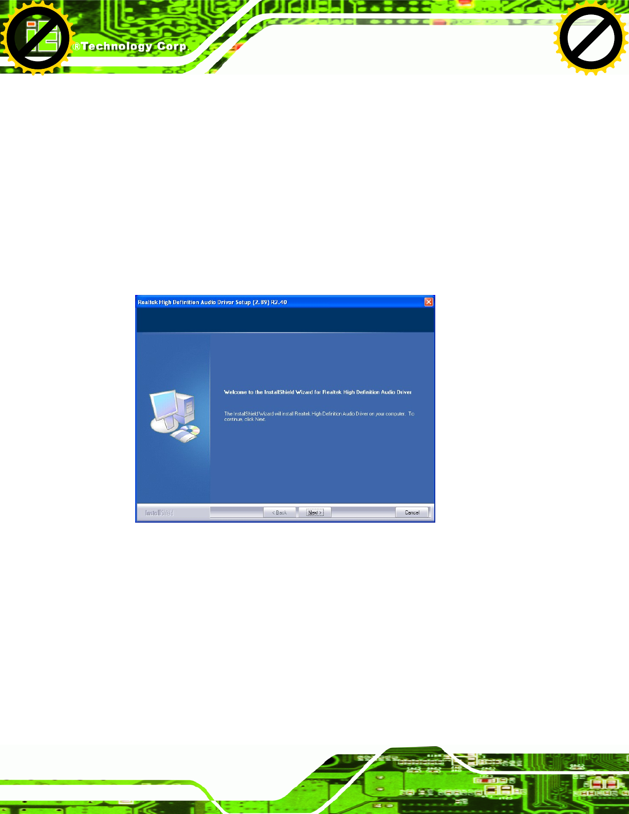
Step 4: The Audio Driver Welcome Screen in Figure 5-18 appears.
Step 5: Click Next to continue.
Figure 5-18: Audio Driver Welcome Screen
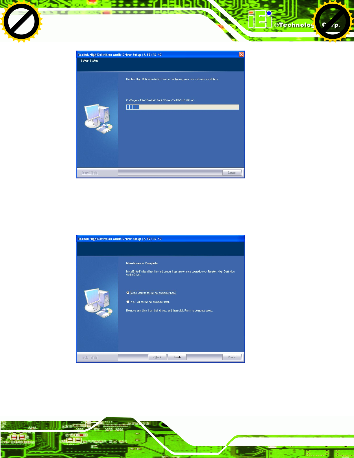
Step 6: The audio driver installation begins. See Figure 5-19.
Click to buy NOW!
P
D
F
-
X
C
h
a
n
g
e
V
i
e
w
e
r
w
w
w
.
d
o
c
u
-
t
r
a
c
k
.
c
o
m
Click to buy NOW!
P
D
F
-
X
C
h
a
n
g
e
V
i
e
w
e
r
w
w
w
.
d
o
c
u
-
t
r
a
c
k
.
c
o
m
UPC-V312-D525 Panel PC
Page 91
Figure 5-19: Audio Driver Installation
Step 7: When the installation is complete, the screen in Figure 5-20 appears.
Step 8: Select “Yes, I want to restart my computer now” and click Finish. Step 0:
Figure 5-20: AC’97 Driver Installation Complete
Click to buy NOW!
P
D
F
-
X
C
h
a
n
g
e
V
i
e
w
e
r
w
w
w
.
d
o
c
u
-
t
r
a
c
k
.
c
o
m
Click to buy NOW!
P
D
F
-
X
C
h
a
n
g
e
V
i
e
w
e
r
w
w
w
.
d
o
c
u
-
t
r
a
c
k
.
c
o
m
UPC-V312-D525 Panel PC
Page 92
5.7 Touch Screen Driver Installation
To install the touch panel software driver, please follow the steps below.
Step 1: Access the driver list. (See Section 5.2)
Step 2: Click “Touch Screen.”
Step 3: Locate the setup file and double click on it.
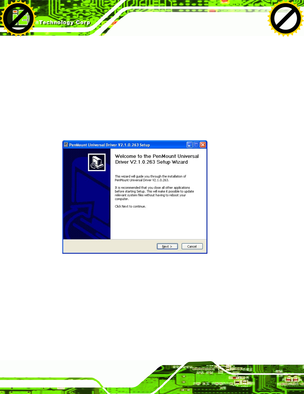
Step 4: A Welcome Screen appears (Figure 5-21).
Step 5: Click NEXT to continue.
Figure 5-21: Touch Screen Driver Welcome Screen
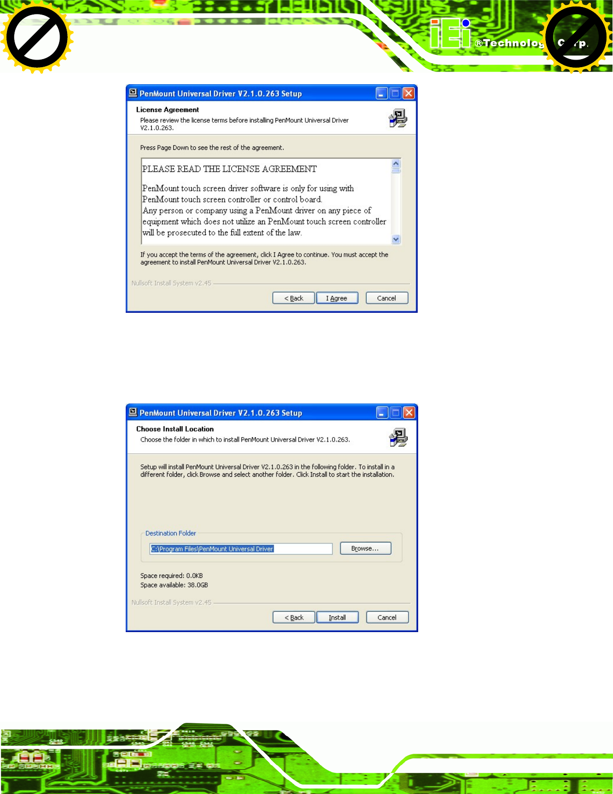
Step 6: The License Agreement shown in Figure 5-22 appears.
Step 7: Click I AGREE to accept and continue.
Click to buy NOW!
P
D
F
-
X
C
h
a
n
g
e
V
i
e
w
e
r
w
w
w
.
d
o
c
u
-
t
r
a
c
k
.
c
o
m
Click to buy NOW!
P
D
F
-
X
C
h
a
n
g
e
V
i
e
w
e
r
w
w
w
.
d
o
c
u
-
t
r
a
c
k
.
c
o
m
UPC-V312-D525 Panel PC
Page 93
Figure 5-22: Touch Screen Driver License Agreement
Step 8: Browse for an install location or use the one suggested (Figure 5-23).
Step 9: Click INSTALL to continue.
Figure 5-23: Touch Screen Driver Choose Install Location
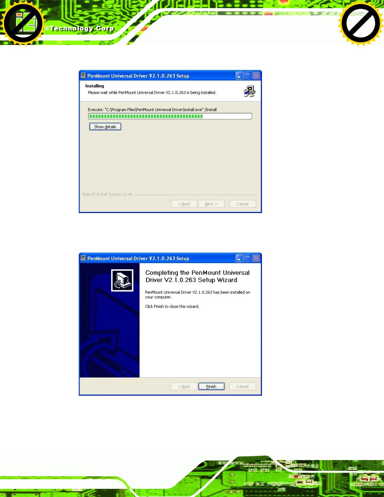
Step 10: The Install screen appears and displays the progress of the installation (Figure
5-24).
Click to buy NOW!
P
D
F
-
X
C
h
a
n
g
e
V
i
e
w
e
r
w
w
w
.
d
o
c
u
-
t
r
a
c
k
.
c
o
m
Click to buy NOW!
P
D
F
-
X
C
h
a
n
g
e
V
i
e
w
e
r
w
w
w
.
d
o
c
u
-
t
r
a
c
k
.
c
o
m
UPC-V312-D525 Panel PC
Page 94
Step 11: Click NEXT to continue.
Figure 5-24: Touch Screen Driver Installation Screen
Step 12: When the installation is complete, click FINISH to exit setup. (Figure 5-25).
Figure 5-25: Touch Screen Driver Update Complete
Click to buy NOW!
P
D
F
-
X
C
h
a
n
g
e
V
i
e
w
e
r
w
w
w
.
d
o
c
u
-
t
r
a
c
k
.
c
o
m
Click to buy NOW!
P
D
F
-
X
C
h
a
n
g
e
V
i
e
w
e
r
w
w
w
.
d
o
c
u
-
t
r
a
c
k
.
c
o
m
UPC-V312-D525 Panel PC
Page 95
5.7.1 Calibrating the Touch Screen
To calibrate the touch screen cursor with the motion of the touch screen pen (or finger),
please follow the steps below:
Step 1: Make sure the touch screen driver is properly installed.
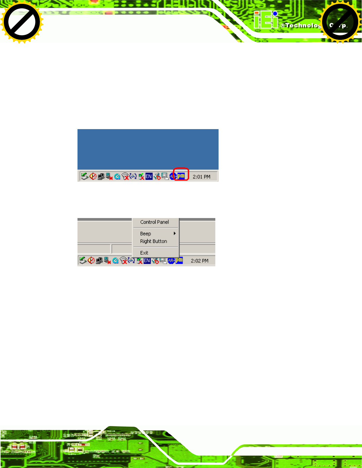
Step 2: Locate the PenMount Monitor icon in the bottom right corner of the screen.
Figure 5-26: PenMount Monitor Icon
Step 3: Click the icon. A pop up menu appears. See Figure 5-27.
Figure 5-27: PenMount Monitor Popup Menu
Step 4: Click Control Panel in the pop up menu shown in Figure 5-27.
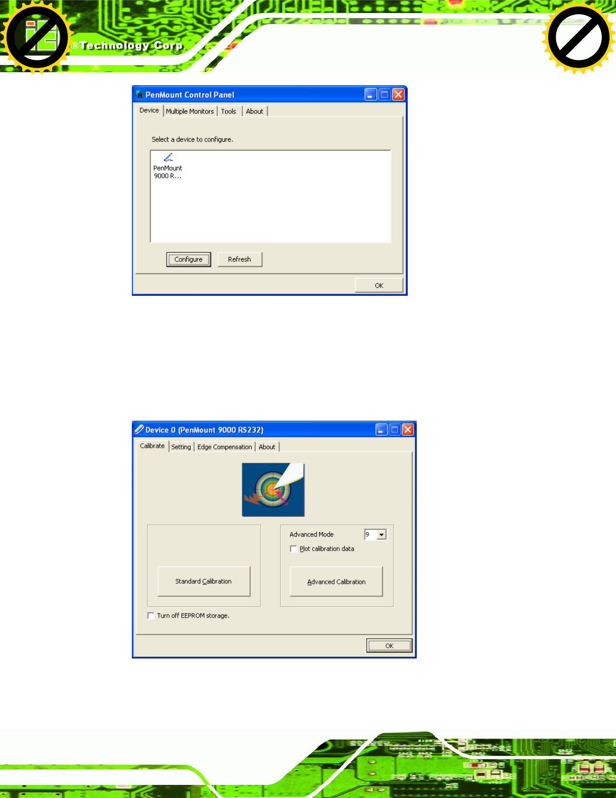
Step 5: The configuration screen in Figure 5-28 appears.
Click to buy NOW!
P
D
F
-
X
C
h
a
n
g
e
V
i
e
w
e
r
w
w
w
.
d
o
c
u
-
t
r
a
c
k
.
c
o
m
Click to buy NOW!
P
D
F
-
X
C
h
a
n
g
e
V
i
e
w
e
r
w
w
w
.
d
o
c
u
-
t
r
a
c
k
.
c
o
m
UPC-V312-D525 Panel PC
Page 96
Figure 5-28: Configuration Screen
Step 6: Double click the PenMount 9000 icon as shown in Figure 5-28.
Step 7: The calibration initiation screen in Figure 5-29 appears.
Step 8: Select the Standard Calibration button as shown in Figure 5-29.
Figure 5-29: Calibration Initiation Screen
Step 9: The calibration screen in is shown. See Figure 5-30.
Click to buy NOW!
P
D
F
-
X
C
h
a
n
g
e
V
i
e
w
e
r
w
w
w
.
d
o
c
u
-
t
r
a
c
k
.
c
o
m
Click to buy NOW!
P
D
F
-
X
C
h
a
n
g
e
V
i
e
w
e
r
w
w
w
.
d
o
c
u
-
t
r
a
c
k
.
c
o
m
UPC-V312-D525 Panel PC
Page 97
Figure 5-30: Calibration Screen
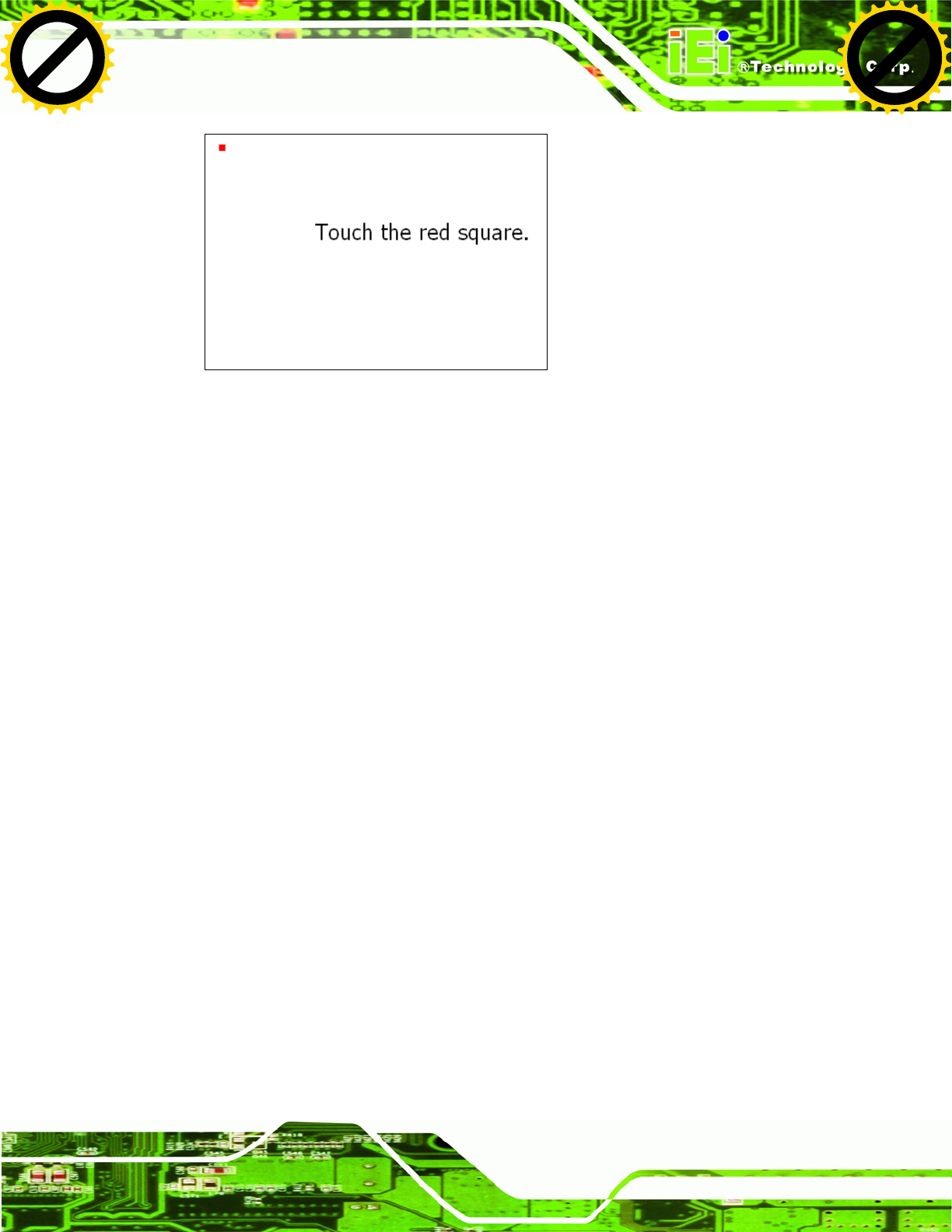
Step 10: Follow the instructions. The user is asked touch the screen at five specified
points after which the screen is calibrated. Step 0:
5.8 GPS Driver Installation
To install the GPS driver, please do the following.
Step 1: Access the driver list. (See Section 5.2)
Step 2: Click “GPS” and select the folder which corresponds to the operating system.
Step 3: Double click the setup file.
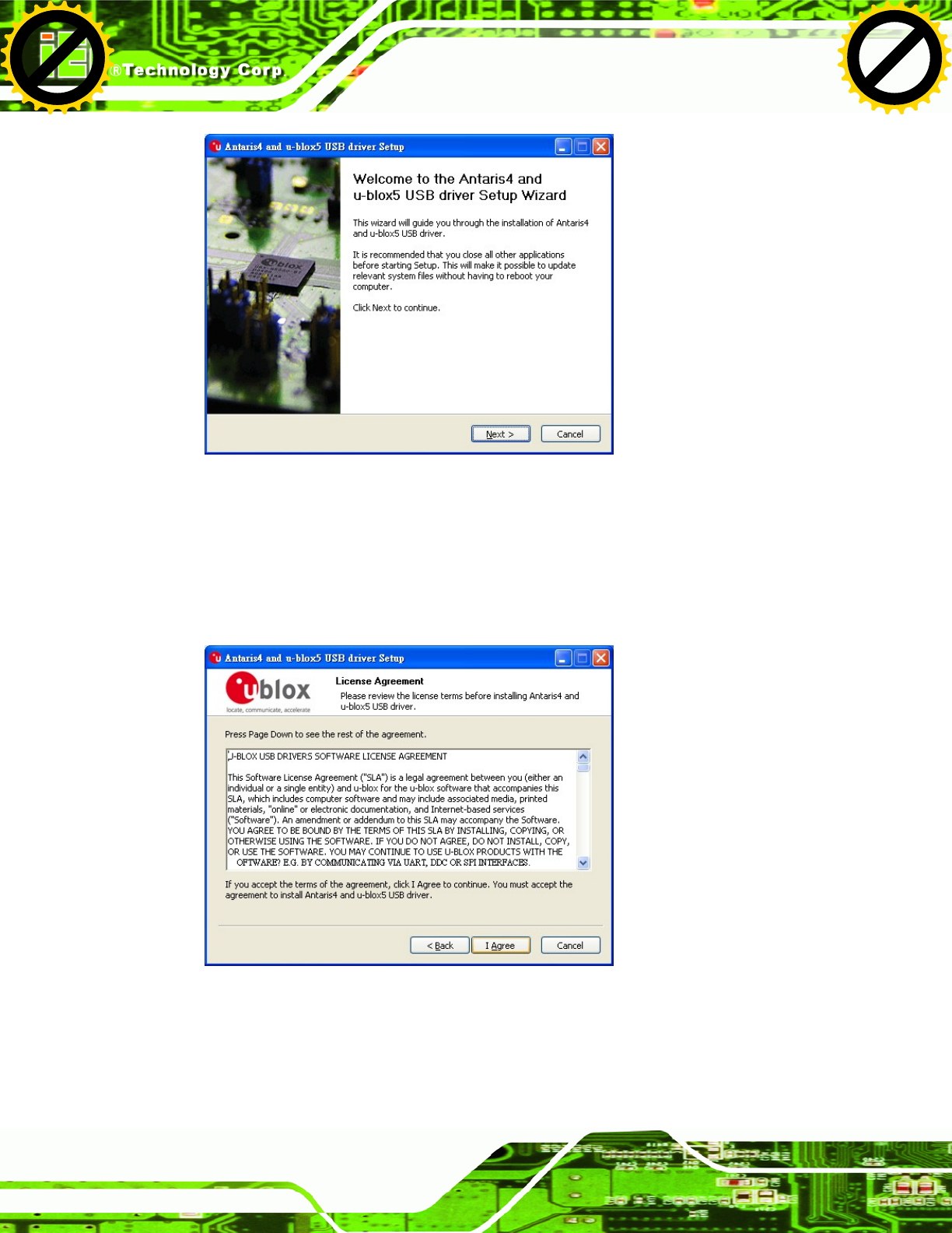
Step 4: The Welcome Screen in Figure 5-31 appears.
Step 5: Click Next to continue.
Click to buy NOW!
P
D
F
-
X
C
h
a
n
g
e
V
i
e
w
e
r
w
w
w
.
d
o
c
u
-
t
r
a
c
k
.
c
o
m
Click to buy NOW!
P
D
F
-
X
C
h
a
n
g
e
V
i
e
w
e
r
w
w
w
.
d
o
c
u
-
t
r
a
c
k
.
c
o
m
UPC-V312-D525 Panel PC
Page 98
Figure 5-31: GPS Driver Welcome Screen
Step 6: The license agreement in Figure 5-32 appears.
Step 7: Read the License Agreement.
Step 8: Click I Agree to continue.
Figure 5-32: GPS Driver Choose Install Location
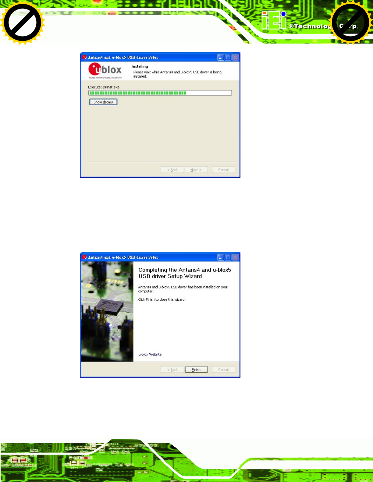
Step 9: The program begins to install.
Click to buy NOW!
P
D
F
-
X
C
h
a
n
g
e
V
i
e
w
e
r
w
w
w
.
d
o
c
u
-
t
r
a
c
k
.
c
o
m
Click to buy NOW!
P
D
F
-
X
C
h
a
n
g
e
V
i
e
w
e
r
w
w
w
.
d
o
c
u
-
t
r
a
c
k
.
c
o
m
UPC-V312-D525 Panel PC
Page 99
Figure 5-33: Installing GPS Driver
Step 10: When the driver installation is complete, the screen in Figure 5-34 appears.
Step 11: Click Finish to save and exit. Step 0:
Figure 5-34: GPS Driver Installation Complete
Click to buy NOW!
P
D
F
-
X
C
h
a
n
g
e
V
i
e
w
e
r
w
w
w
.
d
o
c
u
-
t
r
a
c
k
.
c
o
m
Click to buy NOW!
P
D
F
-
X
C
h
a
n
g
e
V
i
e
w
e
r
w
w
w
.
d
o
c
u
-
t
r
a
c
k
.
c
o
m

UPC-V312-D525 Panel PC
Page 100
5.9 CAN-bus Driver Installation
To install the CAN-bus driver, please follow the steps below.
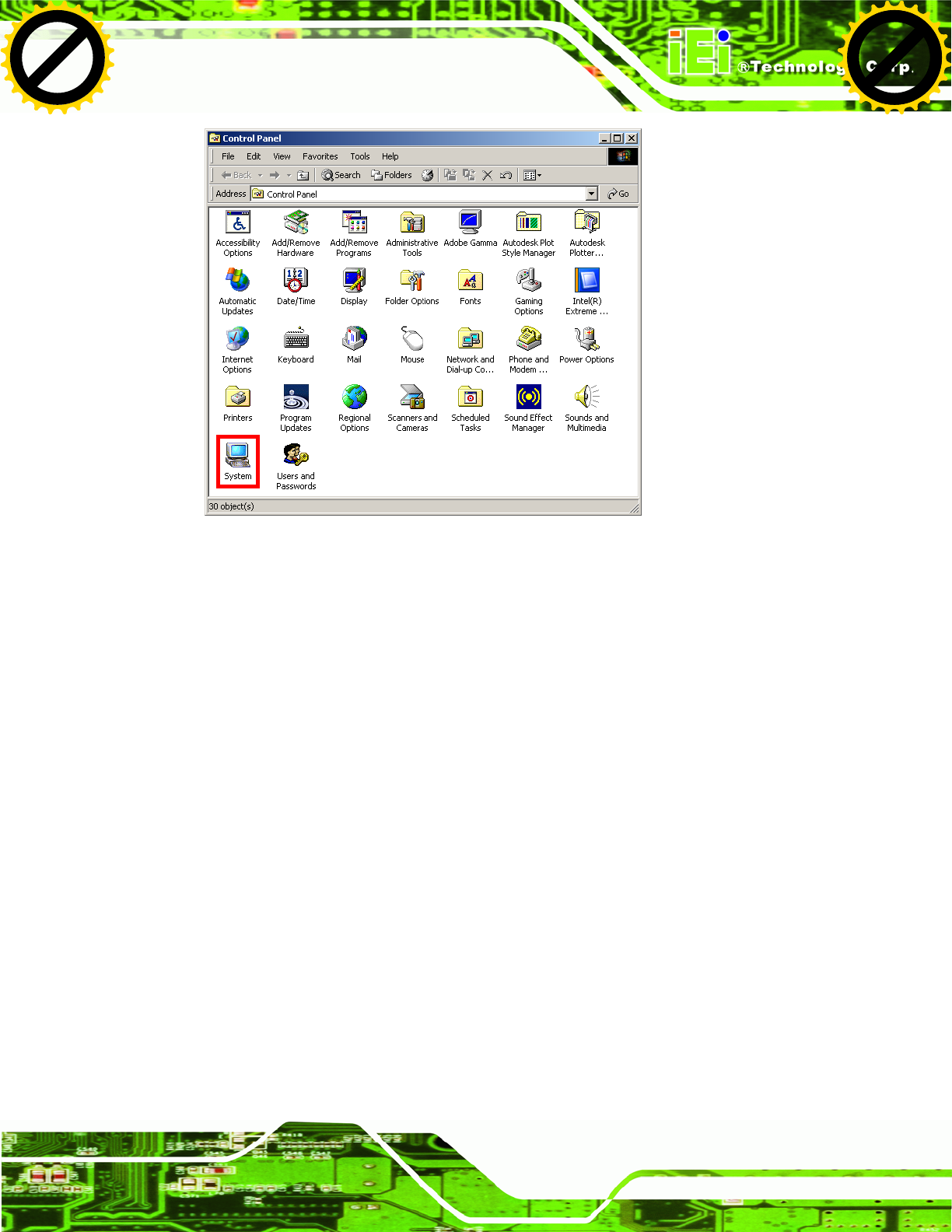
Step 1: Open Windows Control Panel (Figure 5-35).
Figure 5-35: Windows Control Panel
Step 2: Double-click the System icon (Figure 5-36).
Click to buy NOW!
P
D
F
-
X
C
h
a
n
g
e
V
i
e
w
e
r
w
w
w
.
d
o
c
u
-
t
r
a
c
k
.
c
o
m
Click to buy NOW!
P
D
F
-
X
C
h
a
n
g
e
V
i
e
w
e
r
w
w
w
.
d
o
c
u
-
t
r
a
c
k
.
c
o
m
UPC-V312-D525 Panel PC
Page 102
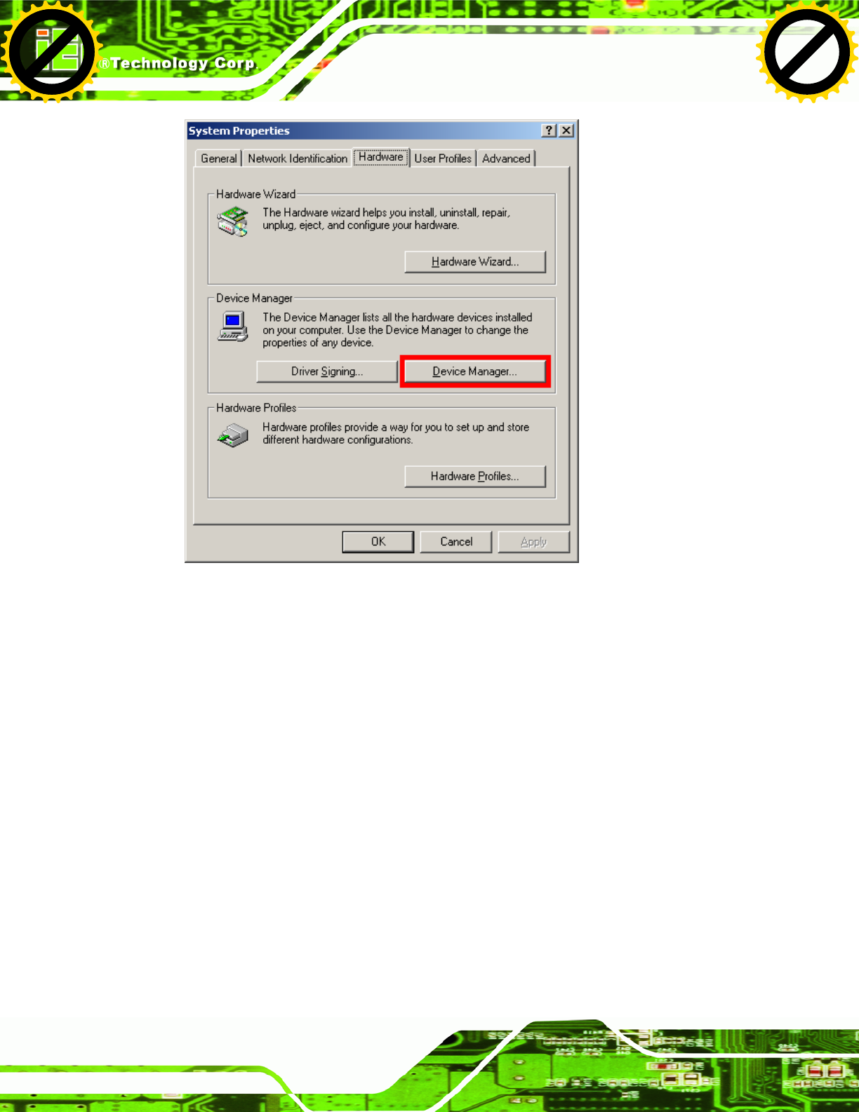
Figure 5-37: Device Manager Tab
Step 4: A list of system hardware devices appears.
Step 5: Double-click the listed device that has question marks next to it (this means
Windows does not recognize the device).
Step 6: The Device Driver Wizard appears (Figure 5-38).
Click to buy NOW!
P
D
F
-
X
C
h
a
n
g
e
V
i
e
w
e
r
w
w
w
.
d
o
c
u
-
t
r
a
c
k
.
c
o
m
Click to buy NOW!
P
D
F
-
X
C
h
a
n
g
e
V
i
e
w
e
r
w
w
w
.
d
o
c
u
-
t
r
a
c
k
.
c
o
m
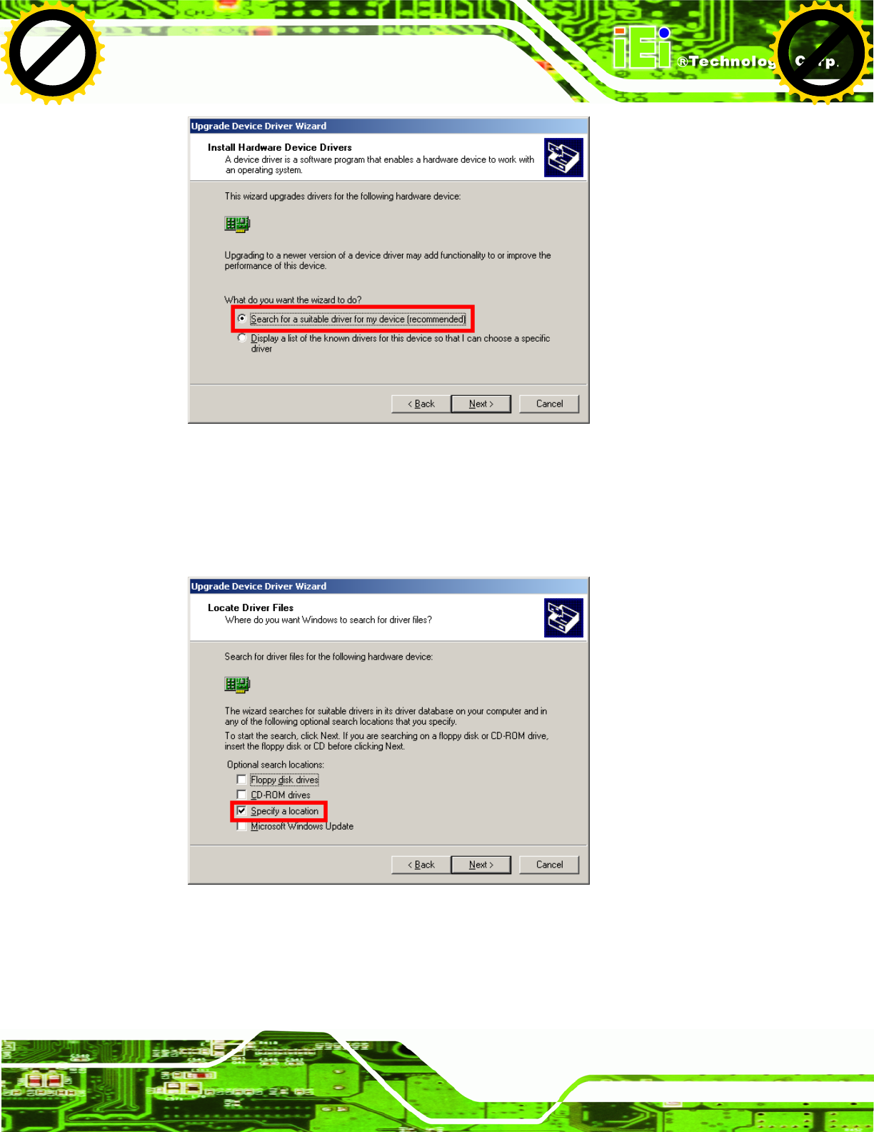
UPC-V312-D525 Panel PC
Page 103
Figure 5-38: Search for Suitable Driver
Step 7: Select “Search for a suitable driver for my device (recommended),” and click
NEXT to continue.
Step 8: Select “Specify a Location” in the Locate Driver Files window (Figure 5-39).
Figure 5-39: Locate Driver Files
Step 9: Click NEXT to continue.
Step 10: The Locate File window appears.
Click to buy NOW!
P
D
F
-
X
C
h
a
n
g
e
V
i
e
w
e
r
w
w
w
.
d
o
c
u
-
t
r
a
c
k
.
c
o
m
Click to buy NOW!
P
D
F
-
X
C
h
a
n
g
e
V
i
e
w
e
r
w
w
w
.
d
o
c
u
-
t
r
a
c
k
.
c
o
m

UPC-V312-D525 Panel PC
Page 104
Step 11: Select the setup file under the “X:\CAN02_Driver” directory in the Locate File
window, where “X:\” is the system CD drive.
Step 12: Click OPEN and the driver is installed.Step 0:
Click to buy NOW!
P
D
F
-
X
C
h
a
n
g
e
V
i
e
w
e
r
w
w
w
.
d
o
c
u
-
t
r
a
c
k
.
c
o
m
Click to buy NOW!
P
D
F
-
X
C
h
a
n
g
e
V
i
e
w
e
r
w
w
w
.
d
o
c
u
-
t
r
a
c
k
.
c
o
m


UPC-V312-D525 Panel PC
Page 106
A.1 BIOS Configuration Options
Below is a list of BIOS configuration options described in Chapter 664.
BIOS Information .................................................................................................................52
System Date [xx/xx/xx]........................................................................................................52
System Time [xx:xx:xx].......................................................................................................53
ACPI Sleep State [S1 (CPU Stop Clock)] ...........................................................................54
ATA/IDE Configurations [Compatible]...............................................................................56
Legacy IDE Channels [PATA Only]....................................................................................57
USB Devices.........................................................................................................................57
Legacy USB Support [Enabled]..........................................................................................58
Serial Port [Enabled]............................................................................................................59
Change Settings [Auto].......................................................................................................59
Serial Port [Enabled]............................................................................................................60
Change Settings [Auto].......................................................................................................60
Serial Port [Enabled]............................................................................................................61
Change Settings [Auto].......................................................................................................61
Serial Port [Enabled]............................................................................................................61
Change Settings [Auto].......................................................................................................62
Serial Port [Enabled]............................................................................................................62
Change Settings [Auto].......................................................................................................62
Serial Port [Enabled]............................................................................................................63
Change Settings [Auto].......................................................................................................63
PC Health Status..................................................................................................................65
Console Redirection [Disabled] .........................................................................................66
Terminal Type [ANSI]...........................................................................................................67
Bits per second [115200].....................................................................................................67
Auto Recovery Function [Disabled]...................................................................................68
High Definition Audio Controller [Enabled] ......................................................................70
USB Function [Enabled]......................................................................................................70
Set Spread Spectrum function [Disabled].........................................................................71
WIFI Support [Enabled] .......................................................................................................71
GPS Support [Disabled] ......................................................................................................71
MIC Support [Enabled] ........................................................................................................71
Click to buy NOW!
P
D
F
-
X
C
h
a
n
g
e
V
i
e
w
e
r
w
w
w
.
d
o
c
u
-
t
r
a
c
k
.
c
o
m
Click to buy NOW!
P
D
F
-
X
C
h
a
n
g
e
V
i
e
w
e
r
w
w
w
.
d
o
c
u
-
t
r
a
c
k
.
c
o
m

UPC-V312-D525 Panel PC
Page 107
Auto Dimming Support [Enabled]......................................................................................71
DVMT Mode Select [DVMT Mode].......................................................................................72
DVMT/FIXED Memory [Maximum] ......................................................................................72
IGD - Boot Type [VBIOS Default]........................................................................................73
LCD Panel Type [1024x768 18bit].......................................................................................73
Backlight Control [Inverted]................................................................................................73
Bootup NumLock State [On]...............................................................................................74
Quiet Boot [Enabled] ...........................................................................................................75
Launch PXE OpROM [Disabled].........................................................................................75
Boot Option #1 [PATA: IEI Technology Corp. ICF]...........................................................75
Save Changes and Reset ....................................................................................................76
Discard Changes and Reset ...............................................................................................76
Restore Defaults ..................................................................................................................76
Save as User Defaults .........................................................................................................76
Restore User Defaults .........................................................................................................76
Click to buy NOW!
P
D
F
-
X
C
h
a
n
g
e
V
i
e
w
e
r
w
w
w
.
d
o
c
u
-
t
r
a
c
k
.
c
o
m
Click to buy NOW!
P
D
F
-
X
C
h
a
n
g
e
V
i
e
w
e
r
w
w
w
.
d
o
c
u
-
t
r
a
c
k
.
c
o
m

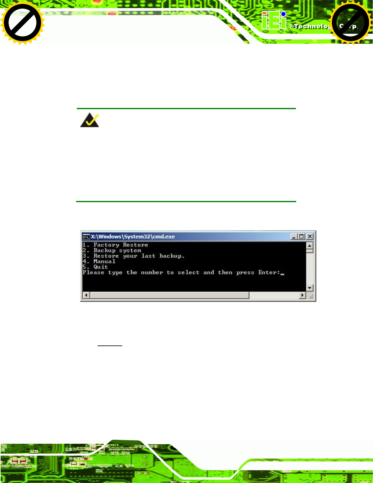
UPC-V312-D525 Panel PC
Page 109
B.1 One Key Recovery Introduction
The IEI one key recovery is an easy-to-use front end for the Norton Ghost system backup
and recovery tool. This tool provides quick and easy shortcuts for creating a backup and
reverting to that backup or reverting to the factory default settings.
NOTE:
The latest One Key Recovery software provides an auto recovery
function that allows a system running Microsoft Windows OS to
automatically restore from the factory default image after encountering
a Blue Screen of Death (BSoD) or a hang for around 10 minutes.
Please refer to Section B.3 for the detailed setup procedure.
The IEI One Key Recovery tool menu is shown below.
Figure B-1: IEI One Key Recovery Tool Menu
Prior to using the IEI One Key Recovery tool (as shown in Figure B-1) to backup or
restore Windows system, five setup procedures are required.
1. Hardware and BIOS setup (see Section B.2.1)
2. Create partitions (see Section B.2.2)
3. Install operating system, drivers and system applications (see Section B.2.3)
4. Build the recovery partition (see Section B.2.4)
5. Create factory default image (see Section B.2.5)
Click to buy NOW!
P
D
F
-
X
C
h
a
n
g
e
V
i
e
w
e
r
w
w
w
.
d
o
c
u
-
t
r
a
c
k
.
c
o
m
Click to buy NOW!
P
D
F
-
X
C
h
a
n
g
e
V
i
e
w
e
r
w
w
w
.
d
o
c
u
-
t
r
a
c
k
.
c
o
m
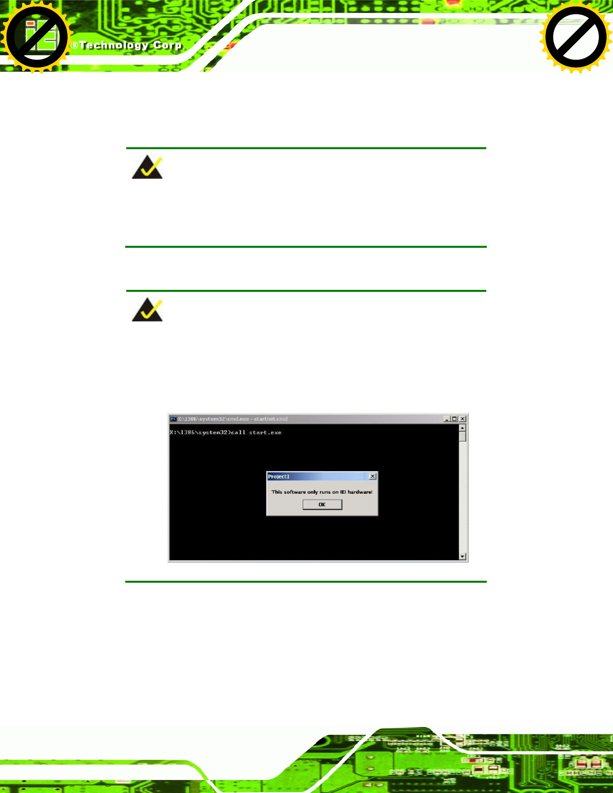
UPC-V312-D525 Panel PC
Page 110
After completing the five initial setup procedures as described above, users can access
the recovery tool by pressing <F3> while booting up the system. The detailed information
of each function is described in Section B.5.
NOTE:
The initial setup procedures for Linux system are described in
Section B.3.
B.1.1 System Requirement
NOTE:
The recovery CD can only be used with IEI products. The software will
fail to run and a warning message will appear when used on non-IEI
hardware.
To create the system backup, the main storage device must be split into two partitions
(three partitions for Linux). The first partition will be for the operating system, while the
second partition will be invisible to the operating system and contain the backup made by
the one key recovery software.
The partition created for recovery images must be big enough to contain both the factory
default image and the user backup image. The size must be calculated before creating the
Click to buy NOW!
P
D
F
-
X
C
h
a
n
g
e
V
i
e
w
e
r
w
w
w
.
d
o
c
u
-
t
r
a
c
k
.
c
o
m
Click to buy NOW!
P
D
F
-
X
C
h
a
n
g
e
V
i
e
w
e
r
w
w
w
.
d
o
c
u
-
t
r
a
c
k
.
c
o
m
UPC-V312-D525 Panel PC
Page 111
partitions. Please take the following table as a reference when calculating the size of the
partition.
OS OS Image after Ghost
Compression Ratio
Windows® 7 7 GB 5 GB 70%
Windows® XPE 776 MB 560 MB 70%
Windows® CE 6.0 36 MB 28 MB 77%
NOTE:
Specialized tools are required to change the partition size if the
operating system is already installed.
B.1.2 Supported Operating System
The recovery CD is compatible with both Microsoft Windows and Linux operating systems
(OS). The supported OS versions are listed below.
Microsoft Windows
o Windows XP (Service Pack 2 or 3 required)
o Windows Vista
o Windows 7
o Windows CE 5.0
o Windows CE 6.0
o Windows XP Embedded
Linux
o Fedora Core 12 (Constantine)
o Fedora Core 11 (Leonidas)
o Fedora Core 10 (Cambridge)
o Fedora Core 8 (Werewolf)
o Fedora Core 7 (Moonshine)
o RedHat RHEL-5.4
o RedHat 9 (Ghirke)
Click to buy NOW!
P
D
F
-
X
C
h
a
n
g
e
V
i
e
w
e
r
w
w
w
.
d
o
c
u
-
t
r
a
c
k
.
c
o
m
Click to buy NOW!
P
D
F
-
X
C
h
a
n
g
e
V
i
e
w
e
r
w
w
w
.
d
o
c
u
-
t
r
a
c
k
.
c
o
m

UPC-V312-D525 Panel PC
Page 112
o Ubuntu 8.10 (Intrepid)
o Ubuntu 7.10 (Gutsy)
o Ubuntu 6.10 (Edgy)
o Debian 5.0 (Lenny)
o Debian 4.0 (Etch)
o SuSe 11.2
o SuSe 10.3
NOTE:
Installing unsupported OS versions may cause the recovery tool to fail.
B.2 Setup Procedure for Windows
Prior to using the recovery tool to backup or restore, a few setup procedures are required.
Step 1: Hardware and BIOS setup (see Section B.2.1)
Step 2: Create partitions (see Section B.2.2)
Step 3: Install operating system, drivers and system applications (see Section B.2.3)
Step 4: Build the recovery partition (see Section B.2.4) or build the auto recovery
partition (see Section B.3)
Step 5: Create factory default image (see Section B.2.5) Step 0:
The detailed descriptions are described in the following sections.
NOTE:
The setup procedures described below are for Microsoft Windows
operating system users. For Linux, most of the setup procedures are
the same except for several steps described in Section B.3.
Click to buy NOW!
P
D
F
-
X
C
h
a
n
g
e
V
i
e
w
e
r
w
w
w
.
d
o
c
u
-
t
r
a
c
k
.
c
o
m
Click to buy NOW!
P
D
F
-
X
C
h
a
n
g
e
V
i
e
w
e
r
w
w
w
.
d
o
c
u
-
t
r
a
c
k
.
c
o
m

UPC-V312-D525 Panel PC
Page 113
B.2.1 Hardware and BIOS Setup
Step 1: Make sure the system is powered off and unplugged.
Step 2: Install a hard drive or SSD in the system. An unformatted and unpartitioned disk
is recommended.
Step 3: Connect an optical disk drive to the system and insert the recovery CD.
Step 4: Turn on the system.
Step 5: Press the <DELETE> key as soon as the system is turned on to enter the BIOS.
Step 6: Select the connected optical disk drive as the 1st boot device. (Boot Æ Boot
Device Priority Æ 1st Boot Device).
Step 7: Save changes and restart the computer. Continue to the next section for
instructions on partitioning the internal storage. Step 0:
B.2.2 Create Partitions
To create the system backup, the main storage device must be split into two partitions
(three partitions for Linux). The first partition will be for the operating system, while the
second partition will be invisible to the operating system and contain the backup made by
the one key recovery software.
Step 1: Put the recovery CD in the optical drive of the system.
Step 2: Boot the system from recovery CD. When prompted, press any key to boot
from the recovery CD. It will take a while to launch the recovery tool. Please be
patient!
Click to buy NOW!
P
D
F
-
X
C
h
a
n
g
e
V
i
e
w
e
r
w
w
w
.
d
o
c
u
-
t
r
a
c
k
.
c
o
m
Click to buy NOW!
P
D
F
-
X
C
h
a
n
g
e
V
i
e
w
e
r
w
w
w
.
d
o
c
u
-
t
r
a
c
k
.
c
o
m
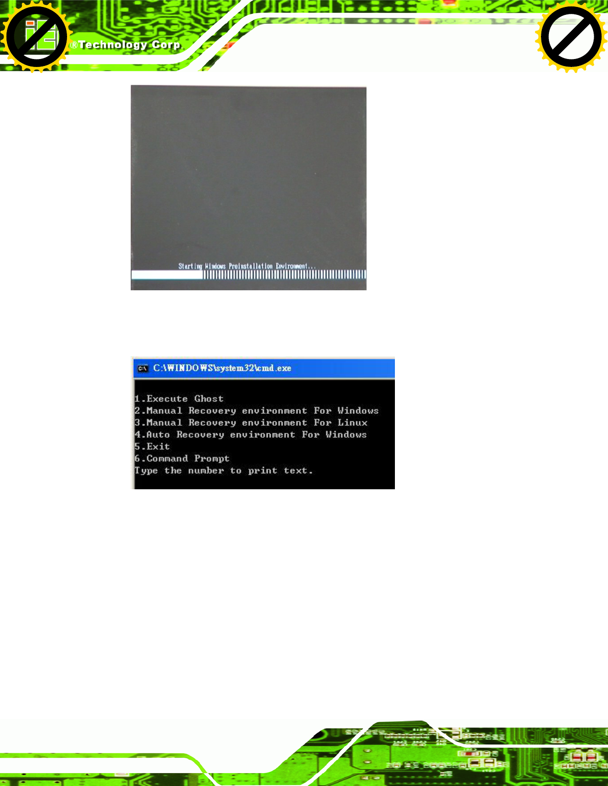
UPC-V312-D525 Panel PC
Page 114
Figure B-2: Launching the Recovery Tool
Step 3: The recovery tool setup menu is shown as below.
Figure B-3: Recovery Tool Setup Menu
Step 4: Press <6> then <Enter>.
Click to buy NOW!
P
D
F
-
X
C
h
a
n
g
e
V
i
e
w
e
r
w
w
w
.
d
o
c
u
-
t
r
a
c
k
.
c
o
m
Click to buy NOW!
P
D
F
-
X
C
h
a
n
g
e
V
i
e
w
e
r
w
w
w
.
d
o
c
u
-
t
r
a
c
k
.
c
o
m
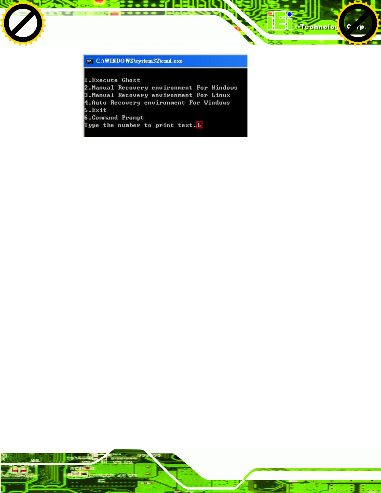
UPC-V312-D525 Panel PC
Page 115
Figure B-4: Command Prompt
Step 5: The command prompt window appears. Type the following commands (marked
in red) to create two partitions. One is for the OS installation; the other is for
saving recovery files and images which will be an invisible partition.
(Press <Enter> after entering each line below)
system32>diskpart
DISKPART>list vol
DISKPART>sel disk 0
DISKPART>create part pri size= ___
DISKPART>assign letter=N
DISKPART>create part pri size= ___
DISKPART>assign letter=F
DISKPART>exit
system32>format N: /fs:ntfs /q /y
system32>format F: /fs:ntfs /q /v:Recovery /y
system32>exit
Click to buy NOW!
P
D
F
-
X
C
h
a
n
g
e
V
i
e
w
e
r
w
w
w
.
d
o
c
u
-
t
r
a
c
k
.
c
o
m
Click to buy NOW!
P
D
F
-
X
C
h
a
n
g
e
V
i
e
w
e
r
w
w
w
.
d
o
c
u
-
t
r
a
c
k
.
c
o
m
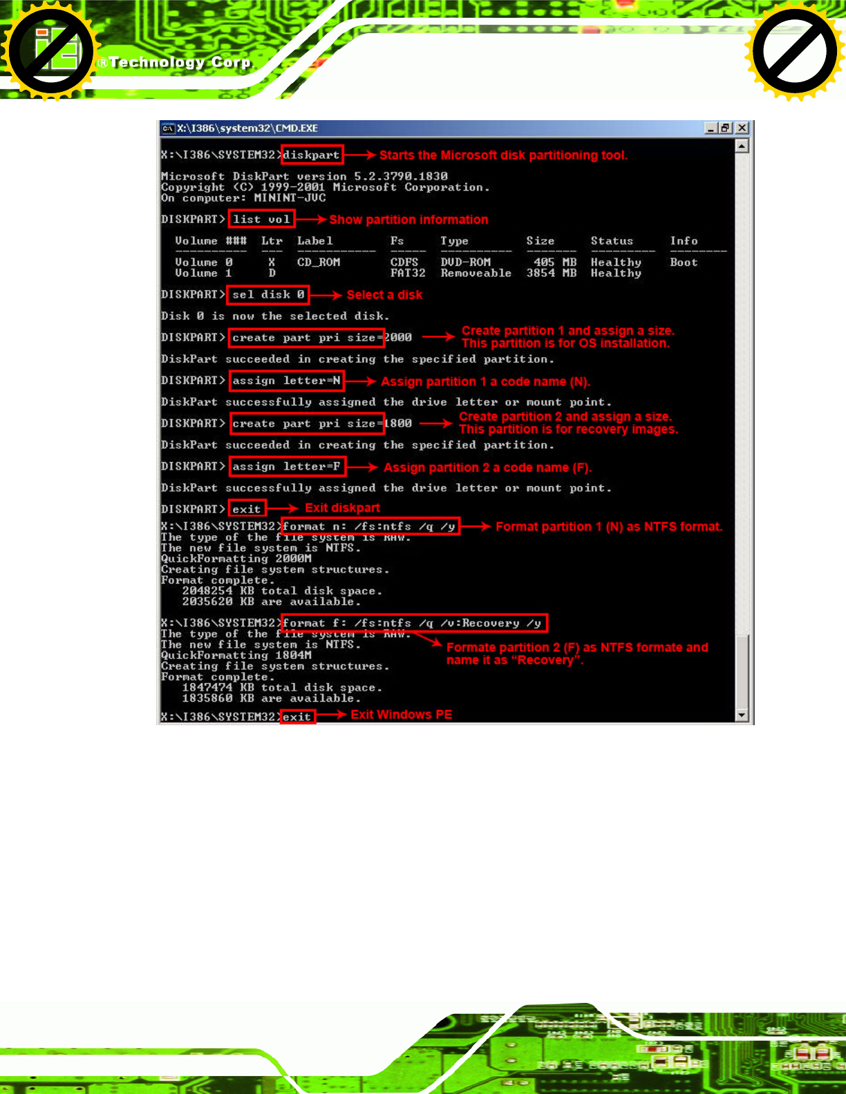
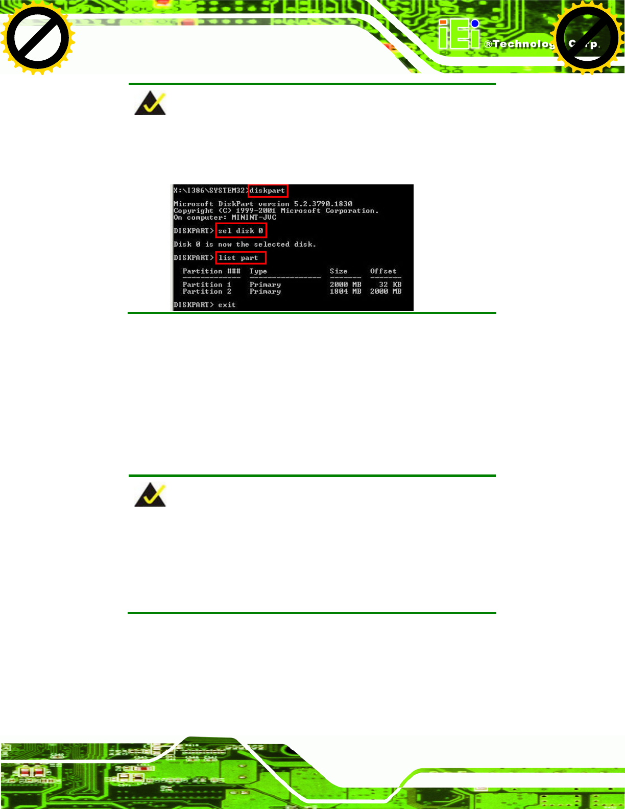
UPC-V312-D525 Panel PC
Page 117
NOTE:
Use the following commands to check if the partitions were created
successfully.
Step 6: Press any key to exit the recovery tool and automatically reboot the system.
Please continue to the following procedure: Build the Recovery Partition.Step 0:
B.2.3 Install Operating System, Drivers and Applications
Install the operating system onto the unlabelled partition. The partition labeled "Recovery"
is for use by the system recovery tool and should not be used for installing the operating
system or any applications.
NOTE:
The operating system installation program may offer to reformat the
chosen partition. DO NOT format the partition again. The partition has
already been formatted and is ready for installing the new operating
system.
To install the operating system, insert the operating system installation CD into the optical
drive. Restart the computer and follow the installation instructions.
Click to buy NOW!
P
D
F
-
X
C
h
a
n
g
e
V
i
e
w
e
r
w
w
w
.
d
o
c
u
-
t
r
a
c
k
.
c
o
m
Click to buy NOW!
P
D
F
-
X
C
h
a
n
g
e
V
i
e
w
e
r
w
w
w
.
d
o
c
u
-
t
r
a
c
k
.
c
o
m
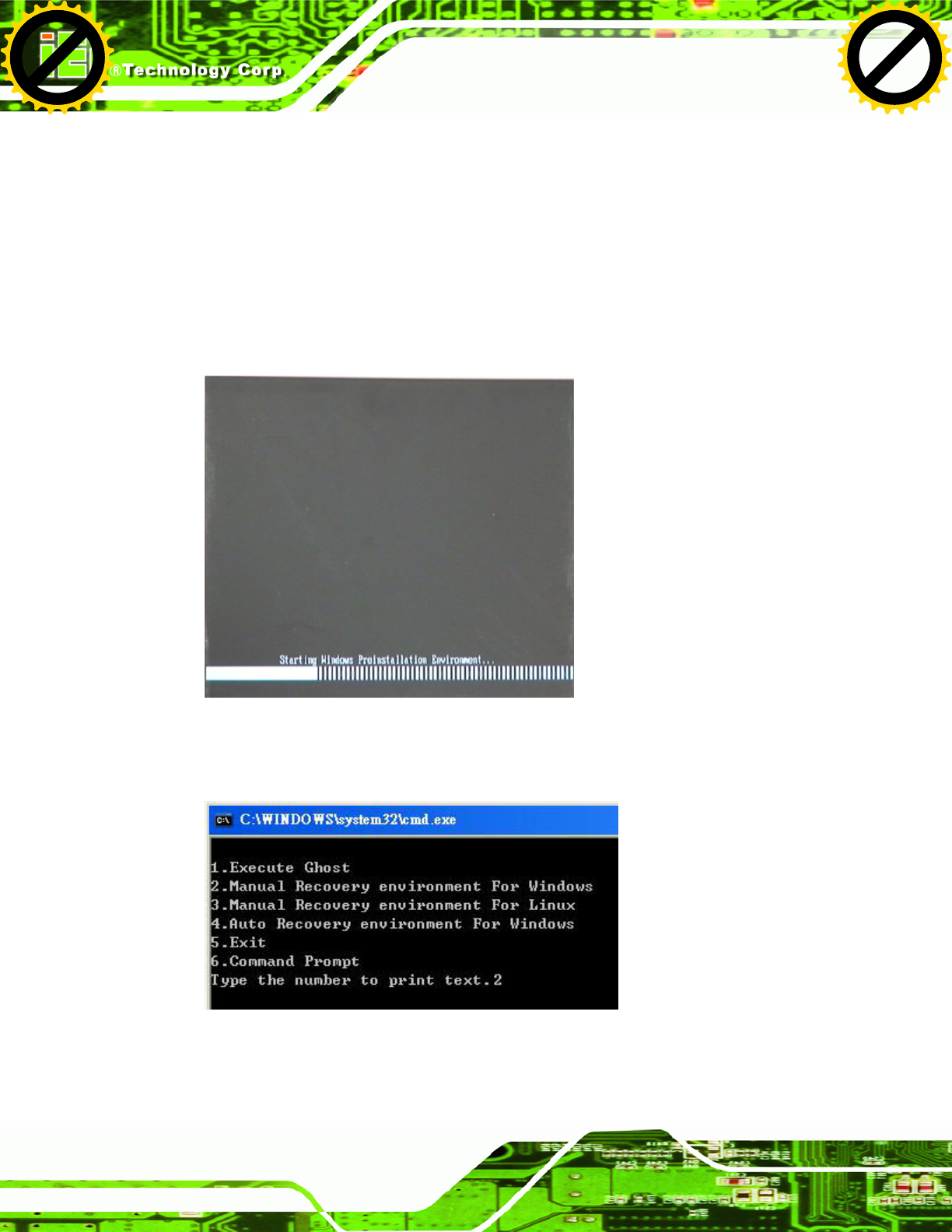
UPC-V312-D525 Panel PC
Page 118
B.2.4 Building the Recovery Partition
Step 1: Put the recover CD in the optical drive.
Step 2: Start the system.
Step 3: Boot the system from the recovery CD. When prompted, press any key to
boot from the recovery CD. It will take a while to launch the recovery tool. Please
be patient!
Figure B-6: Launching the Recovery Tool
Step 4: When the recovery tool setup menu appears, press <2> then <Enter>.
Figure B-7: Manual Recovery Environment for Windows
Click to buy NOW!
P
D
F
-
X
C
h
a
n
g
e
V
i
e
w
e
r
w
w
w
.
d
o
c
u
-
t
r
a
c
k
.
c
o
m
Click to buy NOW!
P
D
F
-
X
C
h
a
n
g
e
V
i
e
w
e
r
w
w
w
.
d
o
c
u
-
t
r
a
c
k
.
c
o
m
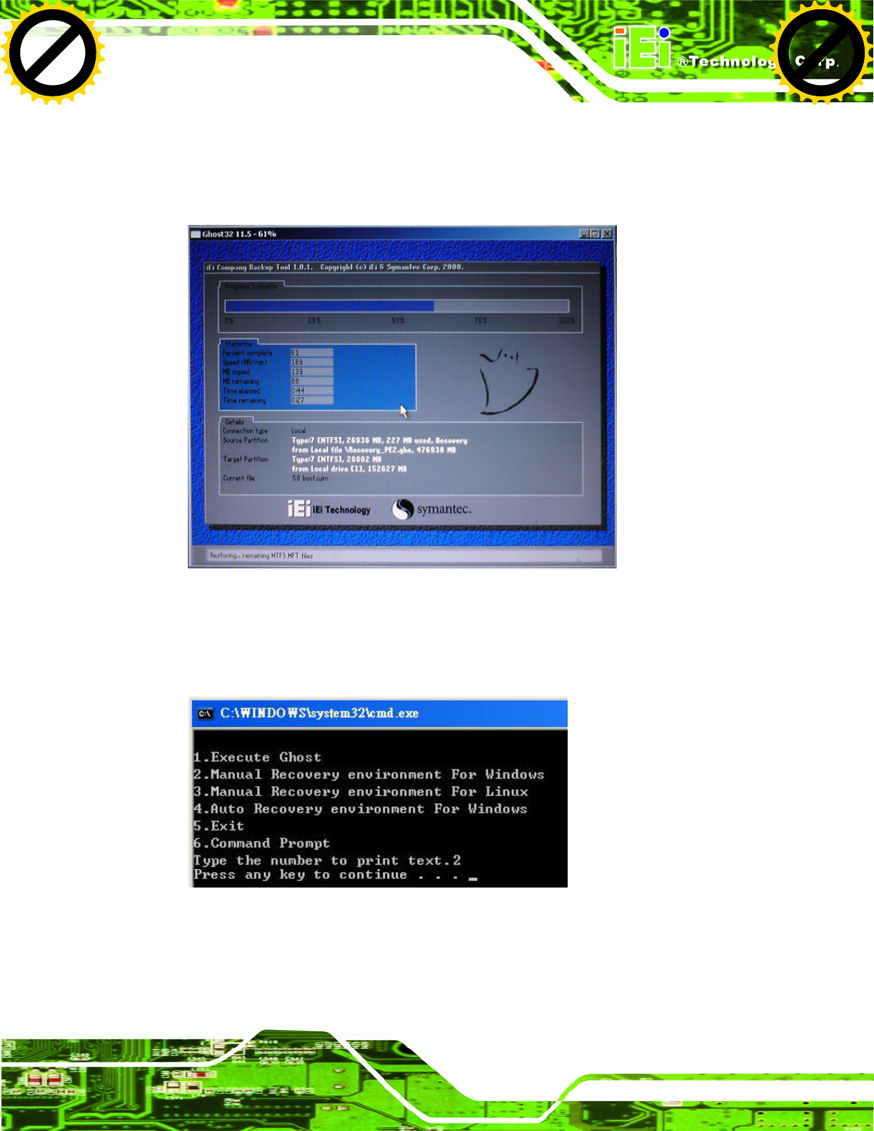
UPC-V312-D525 Panel PC
Page 119
Step 5: The Symantec Ghost window appears and starts configuring the system to build
a recovery partition. In this process the partition created for recovery files in
Section B.2.2 is hidden and the recovery tool is saved in this partition.
Figure B-8: Building the Recovery Partition
Step 6: After completing the system configuration, press any key in the following window
to reboot the system.
Figure B-9: Press Any Key to Continue
Step 7: Eject the recovery CD. Step 0:
Click to buy NOW!
P
D
F
-
X
C
h
a
n
g
e
V
i
e
w
e
r
w
w
w
.
d
o
c
u
-
t
r
a
c
k
.
c
o
m
Click to buy NOW!
P
D
F
-
X
C
h
a
n
g
e
V
i
e
w
e
r
w
w
w
.
d
o
c
u
-
t
r
a
c
k
.
c
o
m
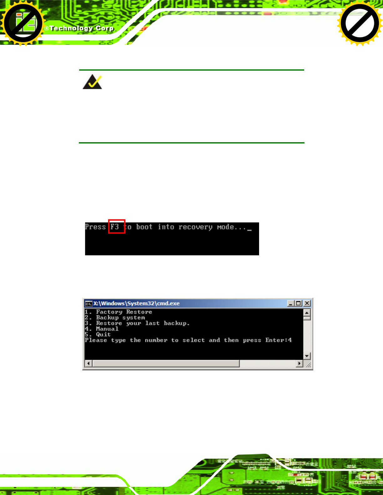
UPC-V312-D525 Panel PC
Page 120
B.2.5 Create Factory Default Image
NOTE:
Before creating the factory default image, please configure the system
to a factory default environment, including driver and application
installations.
To create a factory default image, please follow the steps below.
Step 1: Turn on the system. When the following screen displays (Figure B-10), press
the <F3> key to access the recovery tool. The message will display for 10
seconds, please press F3 before the system boots into the operating system.
Figure B-10: Press F3 to Boot into Recovery Mode
Step 2: The recovery tool menu appears. Type <4> and press <Enter>. (Figure B-11)
Figure B-11: Recovery Tool Menu
Step 3: The About Symantec Ghost window appears. Click OK button to continue.
Click to buy NOW!
P
D
F
-
X
C
h
a
n
g
e
V
i
e
w
e
r
w
w
w
.
d
o
c
u
-
t
r
a
c
k
.
c
o
m
Click to buy NOW!
P
D
F
-
X
C
h
a
n
g
e
V
i
e
w
e
r
w
w
w
.
d
o
c
u
-
t
r
a
c
k
.
c
o
m
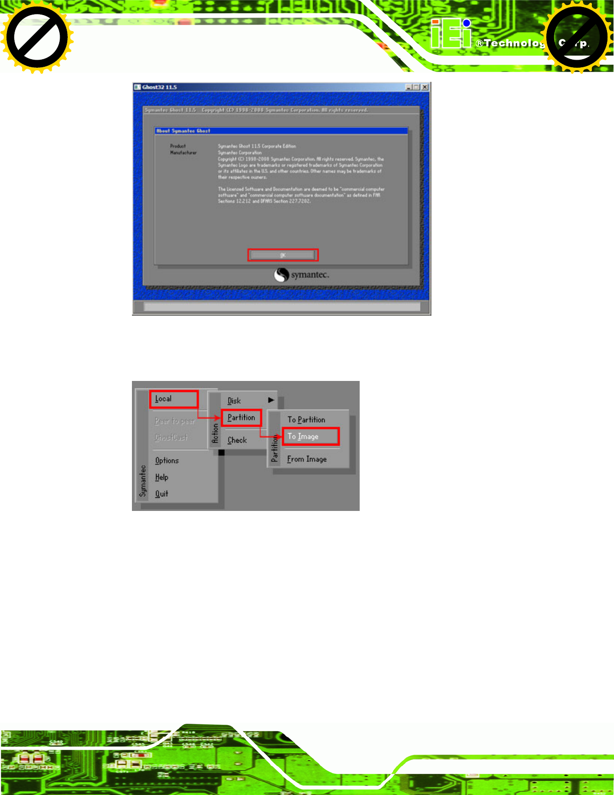
UPC-V312-D525 Panel PC
Page 121
Figure B-12: About Symantec Ghost Window
Step 4: Use mouse to navigate to the option shown below (Figure B-13).
Figure B-13: Symantec Ghost Path
Step 5: Select the local source drive (Drive 1) as shown in Figure B-14. Then click OK.
Click to buy NOW!
P
D
F
-
X
C
h
a
n
g
e
V
i
e
w
e
r
w
w
w
.
d
o
c
u
-
t
r
a
c
k
.
c
o
m
Click to buy NOW!
P
D
F
-
X
C
h
a
n
g
e
V
i
e
w
e
r
w
w
w
.
d
o
c
u
-
t
r
a
c
k
.
c
o
m
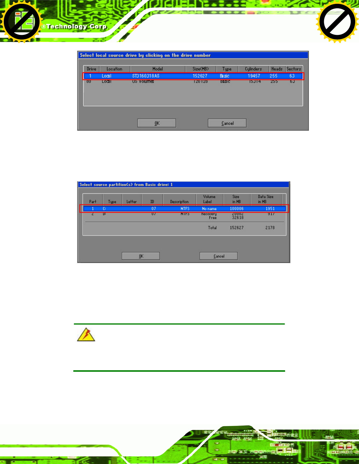
UPC-V312-D525 Panel PC
Page 122
Figure B-14: Select a Local Source Drive
Step 6: Select a source partition (Part 1) from basic drive as shown in Figure B-15.
Then click OK.
Figure B-15: Select a Source Partition from Basic Drive
Step 7: Select 1.2: [Recovery] NTFS drive and enter a file name called iei
(Figure B-16). Click Save. The factory default image will then be saved in the
selected recovery drive and named IEI.GHO.
WARNING:
The file name of the factory default image must be iei.GHO.
Click to buy NOW!
P
D
F
-
X
C
h
a
n
g
e
V
i
e
w
e
r
w
w
w
.
d
o
c
u
-
t
r
a
c
k
.
c
o
m
Click to buy NOW!
P
D
F
-
X
C
h
a
n
g
e
V
i
e
w
e
r
w
w
w
.
d
o
c
u
-
t
r
a
c
k
.
c
o
m
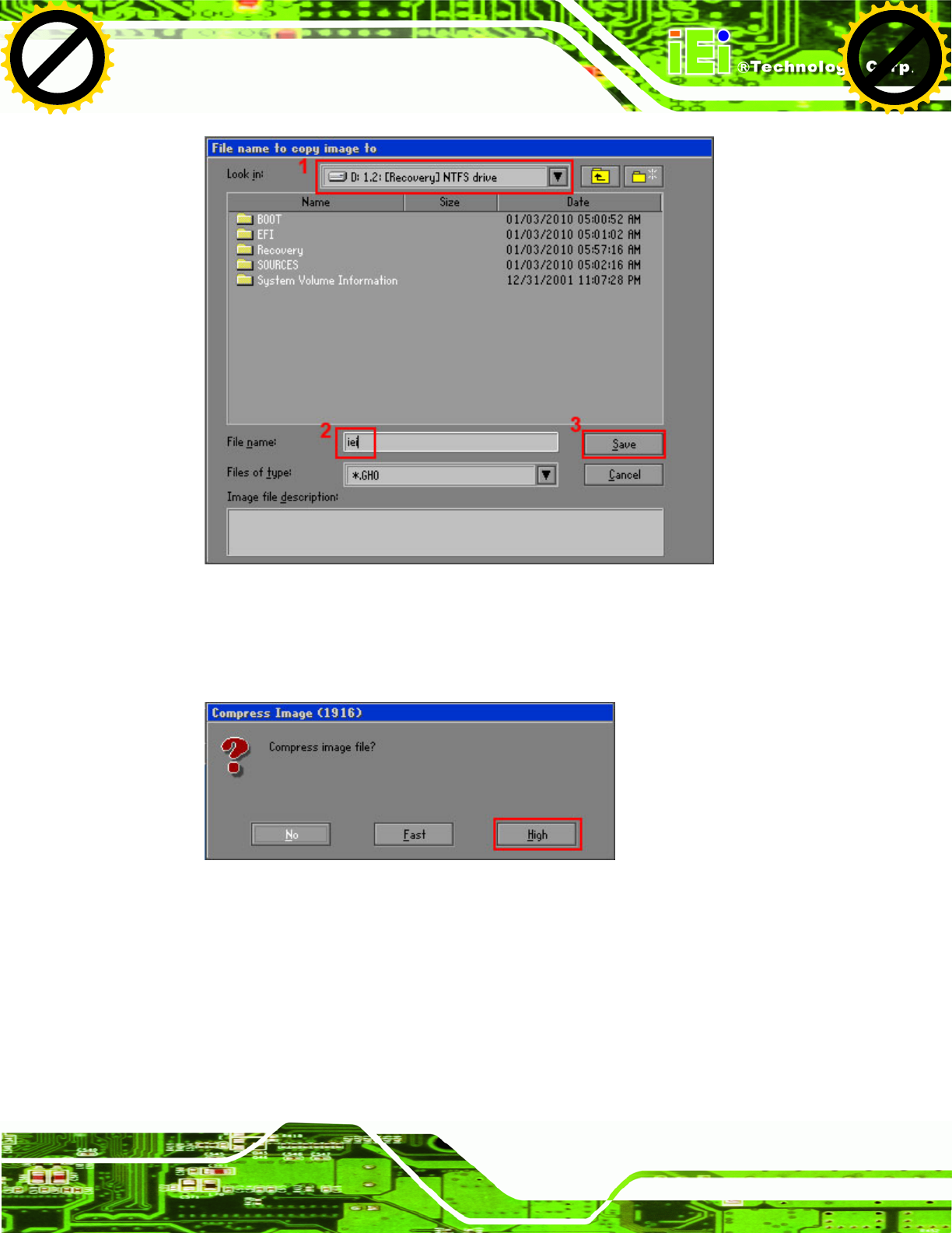
UPC-V312-D525 Panel PC
Page 123
Figure B-16: File Name to Copy Image to
Step 8: When the Compress Image screen in Figure B-17 prompts, click High to make
the image file smaller.
Figure B-17: Compress Image
Click to buy NOW!
P
D
F
-
X
C
h
a
n
g
e
V
i
e
w
e
r
w
w
w
.
d
o
c
u
-
t
r
a
c
k
.
c
o
m
Click to buy NOW!
P
D
F
-
X
C
h
a
n
g
e
V
i
e
w
e
r
w
w
w
.
d
o
c
u
-
t
r
a
c
k
.
c
o
m
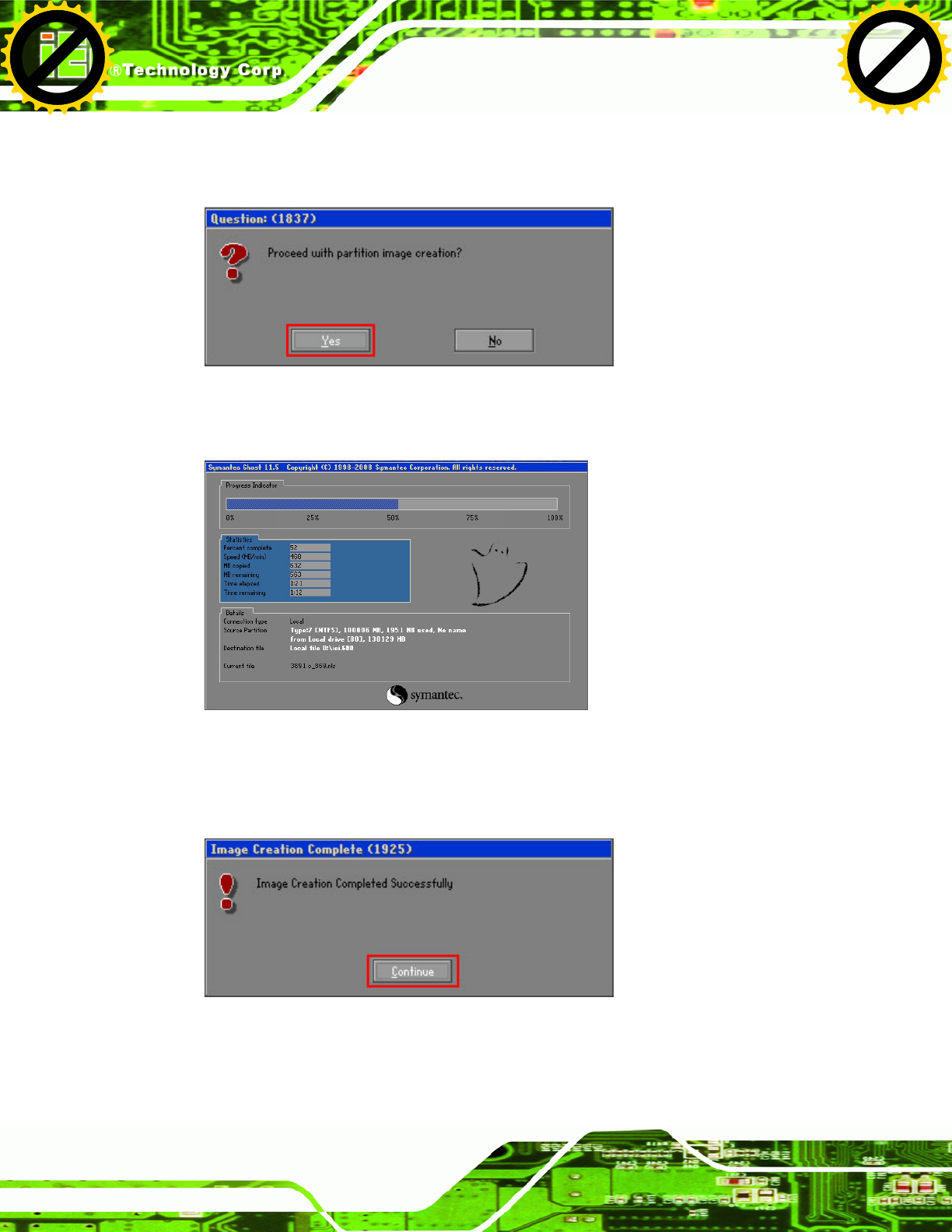
UPC-V312-D525 Panel PC
Page 124
Step 9: The Proceed with partition image creation window appears, click Yes to
continue.
Figure B-18: Image Creation Confirmation
Step 10: The Symantec Ghost starts to create the factory default image (Figure B-19).
Figure B-19: Image Creation Complete
Step 11: When the image creation completes, a screen prompts as shown in Figure B-20.
Click Continue and close the Ghost window to exit the program.
Figure B-20: Image Creation Complete
Click to buy NOW!
P
D
F
-
X
C
h
a
n
g
e
V
i
e
w
e
r
w
w
w
.
d
o
c
u
-
t
r
a
c
k
.
c
o
m
Click to buy NOW!
P
D
F
-
X
C
h
a
n
g
e
V
i
e
w
e
r
w
w
w
.
d
o
c
u
-
t
r
a
c
k
.
c
o
m
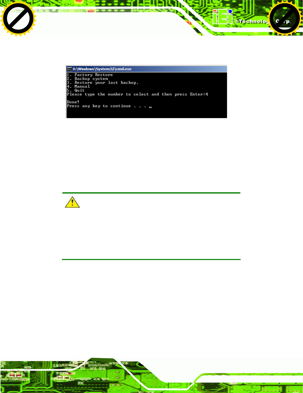
UPC-V312-D525 Panel PC
Page 125
Step 12: The recovery tool main menu window is shown as below. Press any key to
reboot the system. Step 0:
Figure B-21: Press Any Key to Continue
B.3 Auto Recovery Setup Procedure
The auto recovery function allows a system to automatically restore from the factory
default image after encountering a Blue Screen of Death (BSoD) or a hang for around 10
minutes. To use the auto recovery function, follow the steps described in the following
sections.
CAUTION:
The setup procedure may include a step to create a factory default
image. It is suggested to configure the system to a factory default
environment before the configuration, including driver and application
installations.
Step 1: Follow the steps described in Section B.2.1 ~ Section B.2.3 to setup BIOS,
create partitions and install operating system.
Step 2: Install the auto recovery utility into the system by double clicking the
Utility/AUTORECOVERY-SETUP.exe in the One Key Recovery CD. This utility
MUST be installed in the system, otherwise, the system will automatically
restore from the factory default image every ten (10) minutes.
Click to buy NOW!
P
D
F
-
X
C
h
a
n
g
e
V
i
e
w
e
r
w
w
w
.
d
o
c
u
-
t
r
a
c
k
.
c
o
m
Click to buy NOW!
P
D
F
-
X
C
h
a
n
g
e
V
i
e
w
e
r
w
w
w
.
d
o
c
u
-
t
r
a
c
k
.
c
o
m
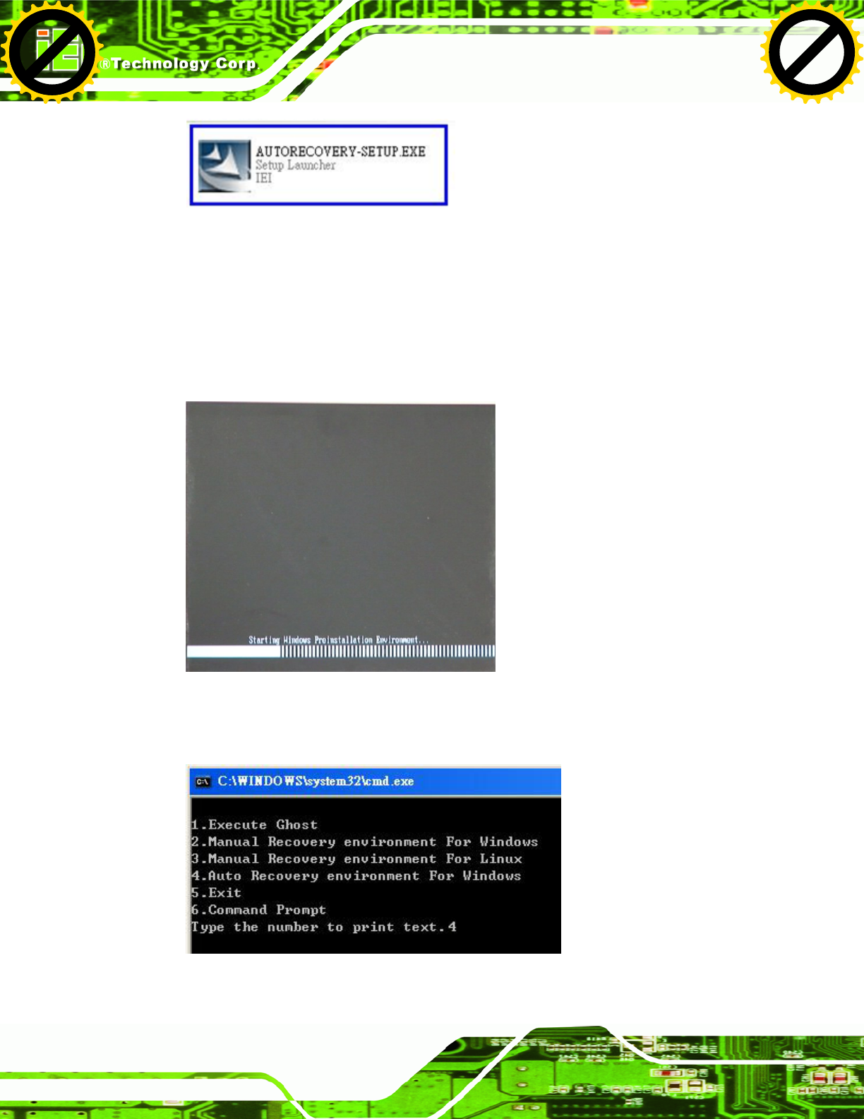
UPC-V312-D525 Panel PC
Page 126
Figure B-22: Auto Recovery Utility
Step 3: Reboot the system from the recovery CD. When prompted, press any key to
boot from the recovery CD. It will take a while to launch the recovery tool. Please
be patient!
Figure B-23: Launching the Recovery Tool
Step 4: When the recovery tool setup menu appears, press <4> then <Enter>.
Figure B-24: Auto Recovery Environment for Windows
Click to buy NOW!
P
D
F
-
X
C
h
a
n
g
e
V
i
e
w
e
r
w
w
w
.
d
o
c
u
-
t
r
a
c
k
.
c
o
m
Click to buy NOW!
P
D
F
-
X
C
h
a
n
g
e
V
i
e
w
e
r
w
w
w
.
d
o
c
u
-
t
r
a
c
k
.
c
o
m
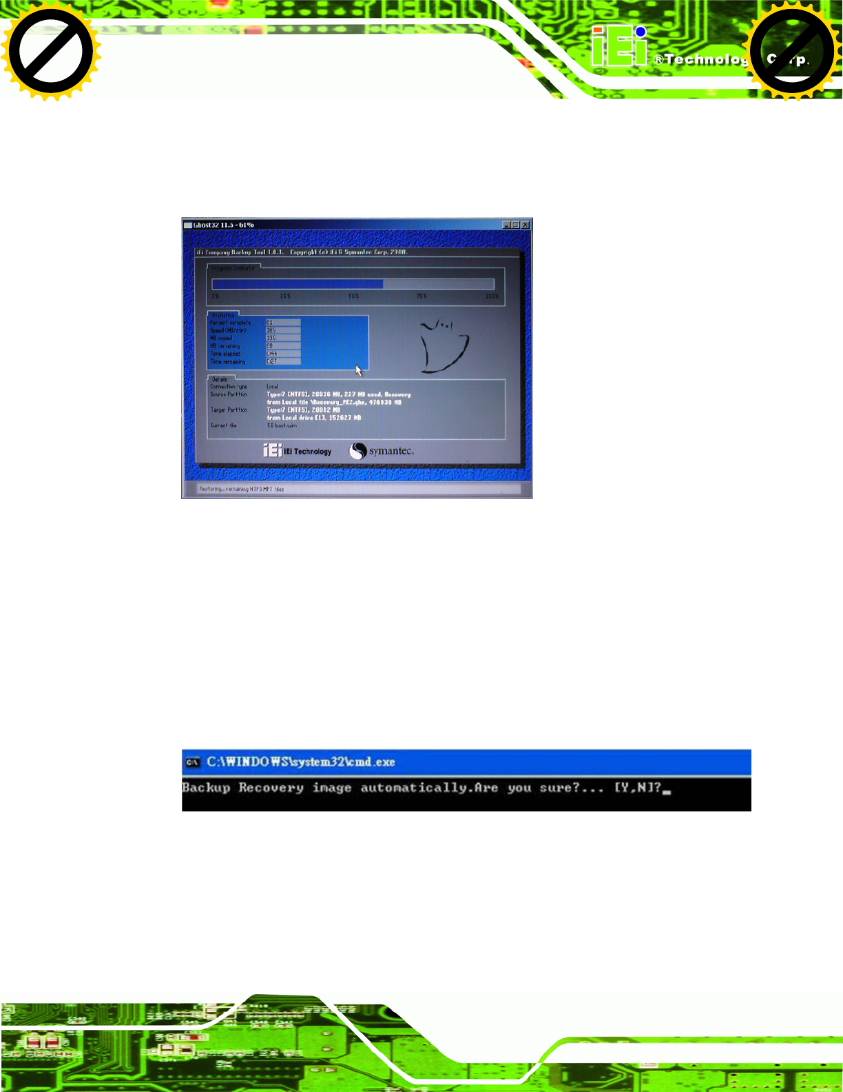
UPC-V312-D525 Panel PC
Page 127
Step 5: The Symantec Ghost window appears and starts configuring the system to build
an auto recovery partition. In this process the partition created for recovery files
in Section B.2.2 is hidden and the auto recovery tool is saved in this partition.
Figure B-25: Building the Auto Recovery Partition
Step 6: After completing the system configuration, the following message prompts to
confirm whether to create a factory default image. Type Y to have the system
create a factory default image automatically. Type N within 6 seconds to skip this
process (The default option is YES). It is suggested to choose YES for this
option.
Figure B-26: Factory Default Image Confirmation
Click to buy NOW!
P
D
F
-
X
C
h
a
n
g
e
V
i
e
w
e
r
w
w
w
.
d
o
c
u
-
t
r
a
c
k
.
c
o
m
Click to buy NOW!
P
D
F
-
X
C
h
a
n
g
e
V
i
e
w
e
r
w
w
w
.
d
o
c
u
-
t
r
a
c
k
.
c
o
m

UPC-V312-D525 Panel PC
Page 128
Step 7: The Symantec Ghost starts to create the factory default image (Figure B-27).
Figure B-27: Image Creation Complete
Step 8: After completing the system configuration, press any key in the following window
to restart the system.
Figure B-28: Press any key to continue
Step 9: Eject the One Key Recovery CD and restart the system.
Step 10: Press the <DELETE> key as soon as the system is turned on to enter the BIOS.
Step 11: Enable the Auto Recovery Function option (Advanced Æ iEi Feature Æ Auto
Recovery Function).
Click to buy NOW!
P
D
F
-
X
C
h
a
n
g
e
V
i
e
w
e
r
w
w
w
.
d
o
c
u
-
t
r
a
c
k
.
c
o
m
Click to buy NOW!
P
D
F
-
X
C
h
a
n
g
e
V
i
e
w
e
r
w
w
w
.
d
o
c
u
-
t
r
a
c
k
.
c
o
m
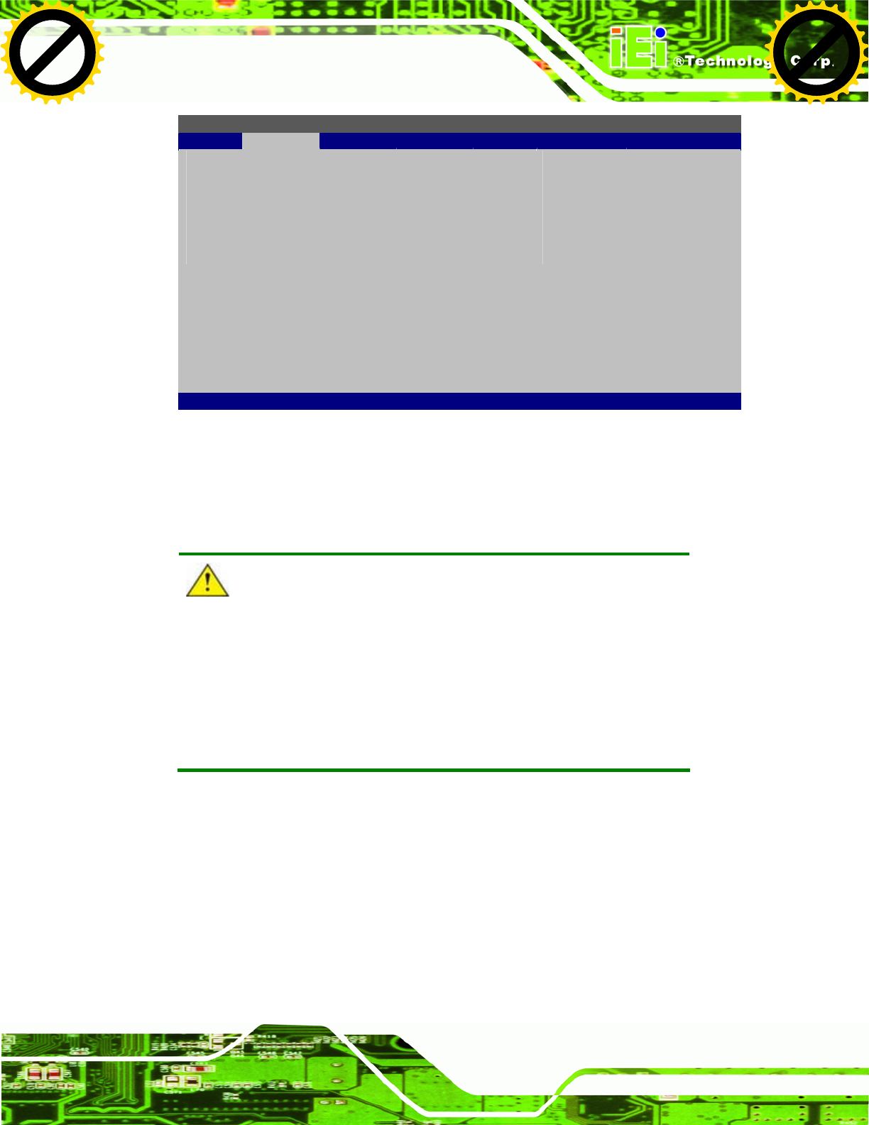
UPC-V312-D525 Panel PC
Page 129
BIOS SETUP UTILITY
Main Advanced PCIPNP Boot Security Chipset Exit
iEi Feature
⎯⎯⎯⎯⎯⎯⎯⎯⎯⎯⎯⎯⎯⎯⎯⎯⎯⎯⎯⎯⎯⎯⎯⎯⎯⎯⎯
Auto Recovery Function [Enabled]
Recover from PXE [Disabled]
ÅÆ
Select Screen
↑ ↓ Select Item
Enter Go to SubScreen
F1 General Help
F10 Save and Exit
ESC Exit
v02.61 ©Copyright 1985-2006, American Megatrends, Inc.
BIOS Menu 19: IEI Feature
Step 12: Save changes and restart the system. If the system encounters a Blue Screen of
Death (BSoD) or a hang for around 10 minutes, it will automatically restore from
the factory default image. Step 0:
CAUTION:
The auto recovery function can only apply on a Microsoft Windows
system running the following OS versions:
Windows XP
Windows Vista
Windows 7
B.4 Setup Procedure for Linux
The initial setup procedure for Linux system is mostly the same with the procedure for
Microsoft Windows. Please follow the steps below to setup recovery tool for Linux OS.
Step 1: Hardware and BIOS setup. Refer to Section B.2.1.
Click to buy NOW!
P
D
F
-
X
C
h
a
n
g
e
V
i
e
w
e
r
w
w
w
.
d
o
c
u
-
t
r
a
c
k
.
c
o
m
Click to buy NOW!
P
D
F
-
X
C
h
a
n
g
e
V
i
e
w
e
r
w
w
w
.
d
o
c
u
-
t
r
a
c
k
.
c
o
m
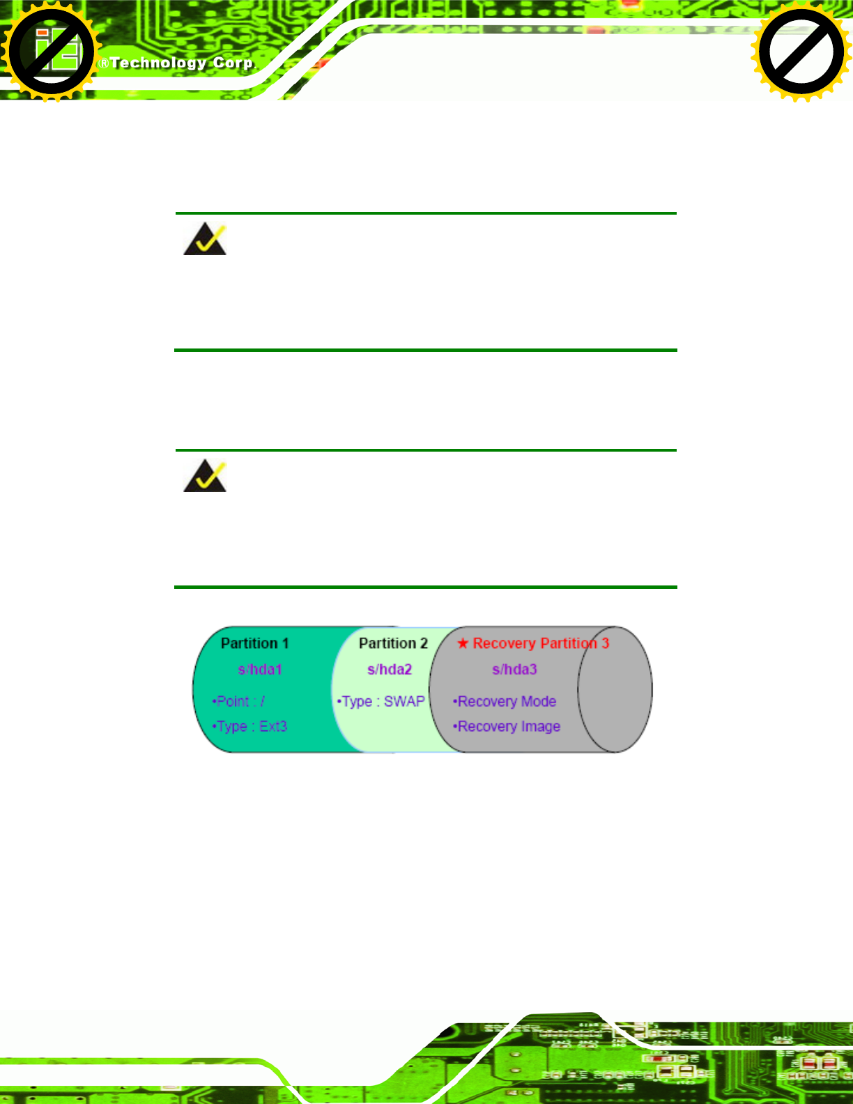
UPC-V312-D525 Panel PC
Page 130
Step 2: Install Linux operating system. Make sure to install GRUB (v0.97 or earlier)
MBR type and Ext3 partition type. Leave enough space on the hard drive to
create the recover partition later.
NOTE:
If the Linux OS is not installed with GRUB (v0.97 or earlier) and Ext3,
the Symantec Ghost may not function properly.
While installing Linux OS, please create two partitions:
Partition 1: /
Partition 2: SWAP
NOTE:
Please reserve enough space for partition 3 for saving recovery
images.
Figure B-29: Partitions for Linux
Step 3: Create a recovery partition. Insert the recovery CD into the optical disk drive.
Follow Step 1 ~ Step 3 described in Section B.2.2. Then type the following
commands (marked in red) to create a partition for recovery images.
system32>diskpart
DISKPART>list vol
DISKPART>sel disk 0
Click to buy NOW!
P
D
F
-
X
C
h
a
n
g
e
V
i
e
w
e
r
w
w
w
.
d
o
c
u
-
t
r
a
c
k
.
c
o
m
Click to buy NOW!
P
D
F
-
X
C
h
a
n
g
e
V
i
e
w
e
r
w
w
w
.
d
o
c
u
-
t
r
a
c
k
.
c
o
m
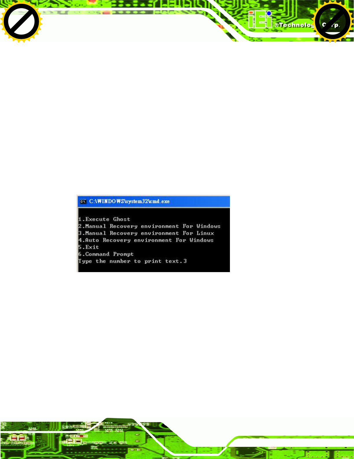
UPC-V312-D525 Panel PC
Page 131
DISKPART>create part pri size= ___
DISKPART>assign letter=N
DISKPART>exit
system32>format N: /fs:ntfs /q /v:Recovery /y
system32>exit
Step 4: Build the recovery partition. Press any key to boot from the recovery CD. It will
take a while to launch the recovery tool. Please be patient. When the recovery
tool setup menu appears, type <3> and press <Enter> (Figure B-30). The
Symantec Ghost window appears and starts configuring the system to build a
recovery partition. After completing the system configuration, press any key to
reboot the system. Eject the recovery CD.
Figure B-30: Manual Recovery Environment for Linux
Step 5: Access the recovery tool main menu by modifying the “menu.lst”. To first
access the recovery tool main menu, the menu.lst must be modified. In Linux,
enter Administrator (root). When prompt appears, type:
cd /boot/grub
vi menu.lst
Click to buy NOW!
P
D
F
-
X
C
h
a
n
g
e
V
i
e
w
e
r
w
w
w
.
d
o
c
u
-
t
r
a
c
k
.
c
o
m
Click to buy NOW!
P
D
F
-
X
C
h
a
n
g
e
V
i
e
w
e
r
w
w
w
.
d
o
c
u
-
t
r
a
c
k
.
c
o
m
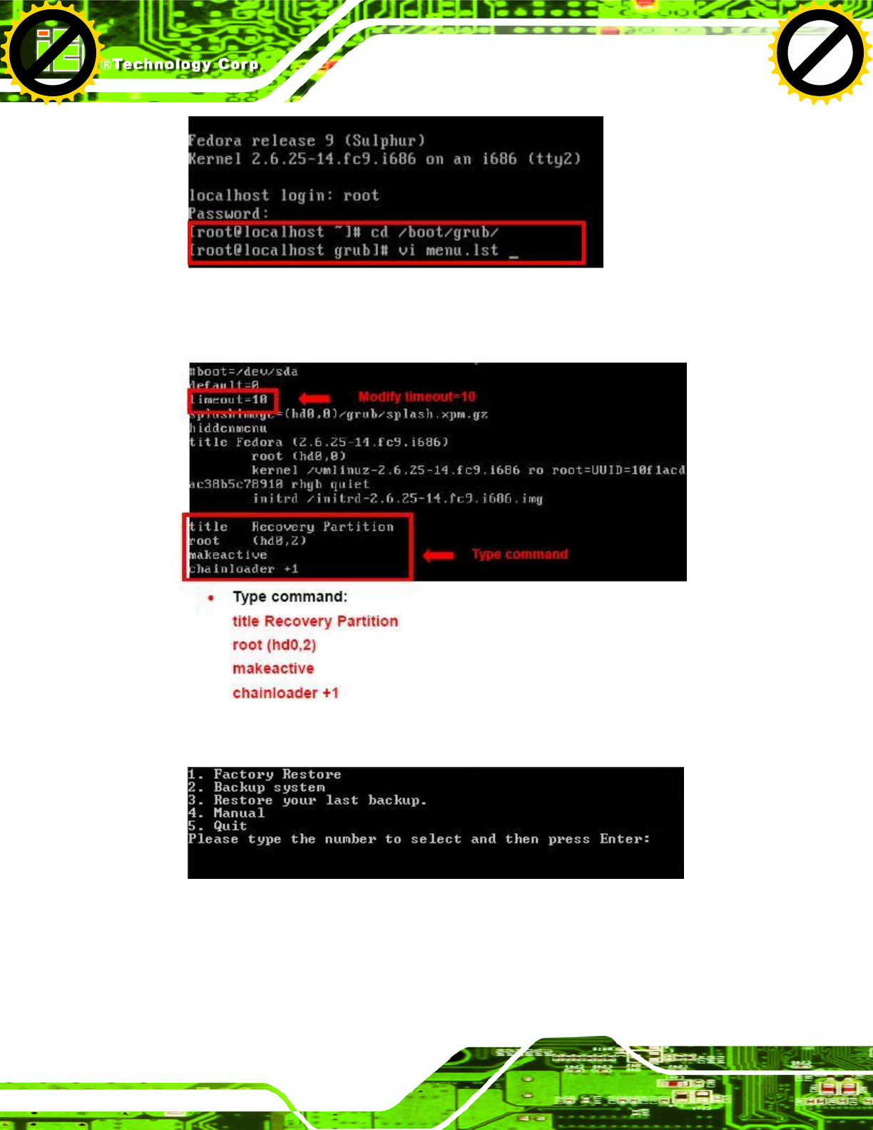
UPC-V312-D525 Panel PC
Page 132
Figure B-31: Access menu.lst in Linux (Text Mode)
Step 6: Modify the menu.lst as shown below.
Step 7: The recovery tool menu appears. (Figure B-32)
Figure B-32: Recovery Tool Menu
Step 8: Create a factory default image. Follow Step 2 ~ Step 12 described in Section
B.2.5 to create a factory default image. Step 0:
Click to buy NOW!
P
D
F
-
X
C
h
a
n
g
e
V
i
e
w
e
r
w
w
w
.
d
o
c
u
-
t
r
a
c
k
.
c
o
m
Click to buy NOW!
P
D
F
-
X
C
h
a
n
g
e
V
i
e
w
e
r
w
w
w
.
d
o
c
u
-
t
r
a
c
k
.
c
o
m
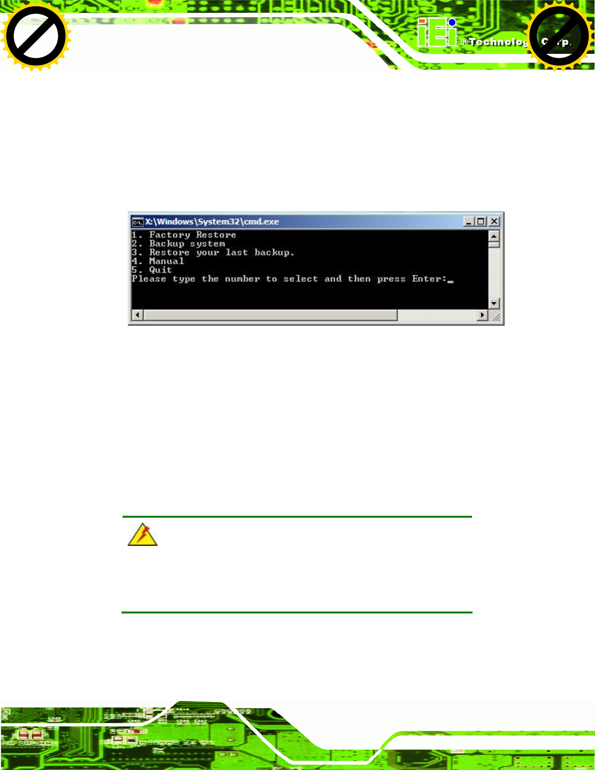
UPC-V312-D525 Panel PC
Page 133
B.5 Recovery Tool Functions
After completing the initial setup procedures as described above, users can access the
recovery tool by pressing <F3> while booting up the system. However, if the setup
procedure in Section B.3 has been completed and the auto recovery function is enabled,
the system will automatically restore from the factory default image without pressing the
F3 key. The recovery tool main menu is shown below.
Figure B-33: Recovery Tool Main Menu
The recovery tool has several functions including:
1. Factory Restore: Restore the factory default image (iei.GHO) created in
Section B.2.5.
2. Backup system: Create a system backup image (iei_user.GHO) which will be
saved in the hidden partition.
3. Restore your last backup: Restore the last system backup image
4. Manual: Enter the Symantec Ghost window to configure manually.
5. Quit: Exit the recovery tool and restart the system.
WARNING:
Please do not turn off the system power during the process of system
recovery or backup.
Click to buy NOW!
P
D
F
-
X
C
h
a
n
g
e
V
i
e
w
e
r
w
w
w
.
d
o
c
u
-
t
r
a
c
k
.
c
o
m
Click to buy NOW!
P
D
F
-
X
C
h
a
n
g
e
V
i
e
w
e
r
w
w
w
.
d
o
c
u
-
t
r
a
c
k
.
c
o
m
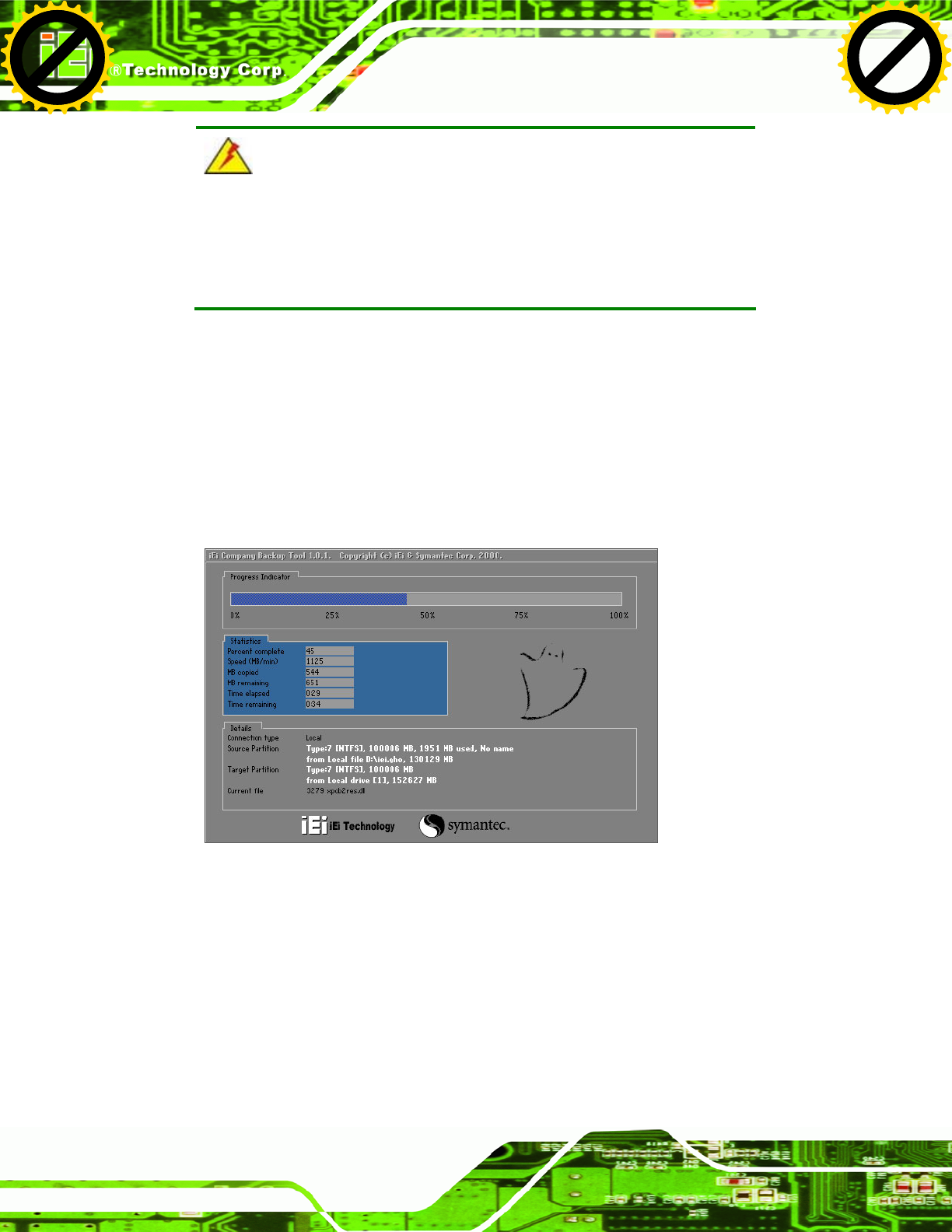
UPC-V312-D525 Panel PC
Page 134
WARNING:
All data in the system will be deleted during the system recovery.
Please backup the system files before restoring the system (either
Factory Restore or Restore Backup).
B.5.1 Factory Restore
To restore the factory default image, please follow the steps below.
Step 1: Type <1> and press <Enter> in the main menu.
Step 2: The Symantec Ghost window appears and starts to restore the factory default. A
factory default image called iei.GHO is created in the hidden Recovery partition.
Figure B-34: Restore Factory Default
Step 3: The screen shown in Figure B-35 appears when completed. Press any key to
reboot the system.
Click to buy NOW!
P
D
F
-
X
C
h
a
n
g
e
V
i
e
w
e
r
w
w
w
.
d
o
c
u
-
t
r
a
c
k
.
c
o
m
Click to buy NOW!
P
D
F
-
X
C
h
a
n
g
e
V
i
e
w
e
r
w
w
w
.
d
o
c
u
-
t
r
a
c
k
.
c
o
m
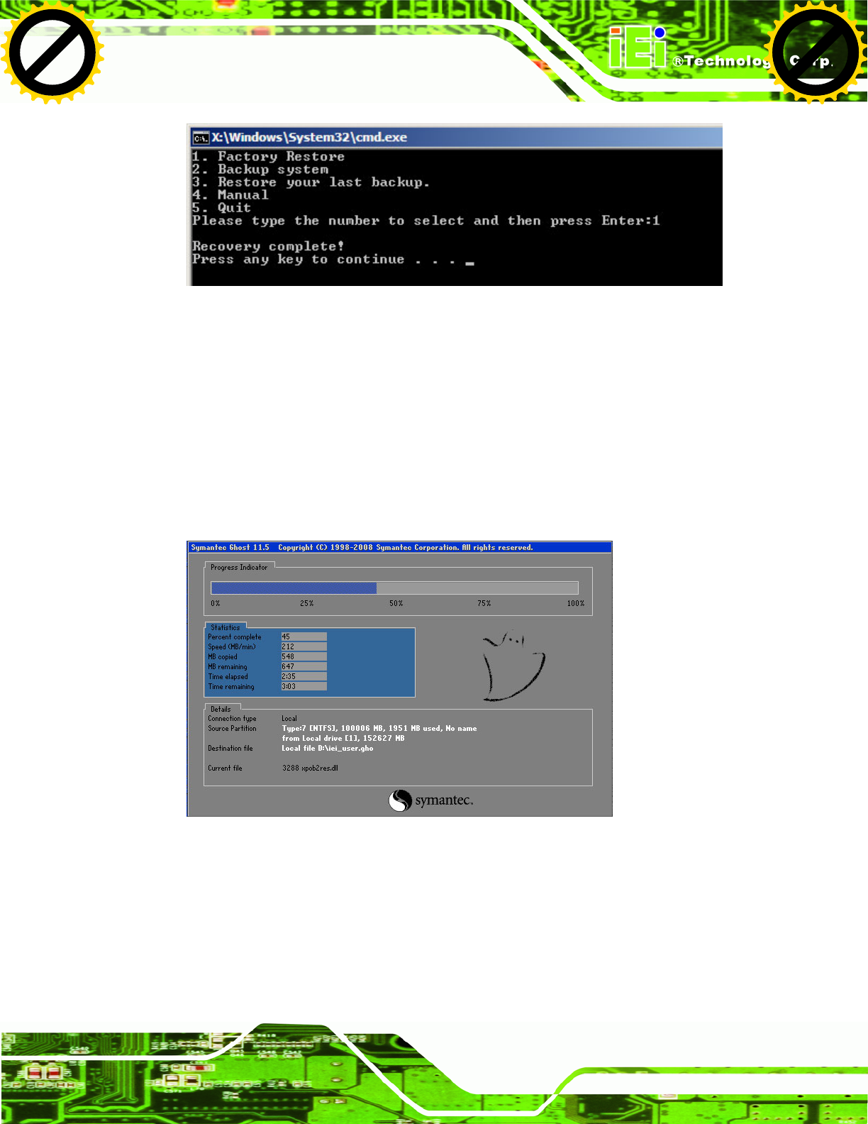
UPC-V312-D525 Panel PC
Page 135
Figure B-35: Recovery Complete Window
B.5.2 Backup System
To backup the system, please follow the steps below.
Step 1: Type <2> and press <Enter> in the main menu.
Step 2: The Symantec Ghost window appears and starts to backup the system. A
backup image called iei_user.GHO is created in the hidden Recovery partition.
Figure B-36: Backup System
Step 3: The screen shown in Figure B-37 appears when system backup is complete.
Press any key to reboot the system.
Click to buy NOW!
P
D
F
-
X
C
h
a
n
g
e
V
i
e
w
e
r
w
w
w
.
d
o
c
u
-
t
r
a
c
k
.
c
o
m
Click to buy NOW!
P
D
F
-
X
C
h
a
n
g
e
V
i
e
w
e
r
w
w
w
.
d
o
c
u
-
t
r
a
c
k
.
c
o
m
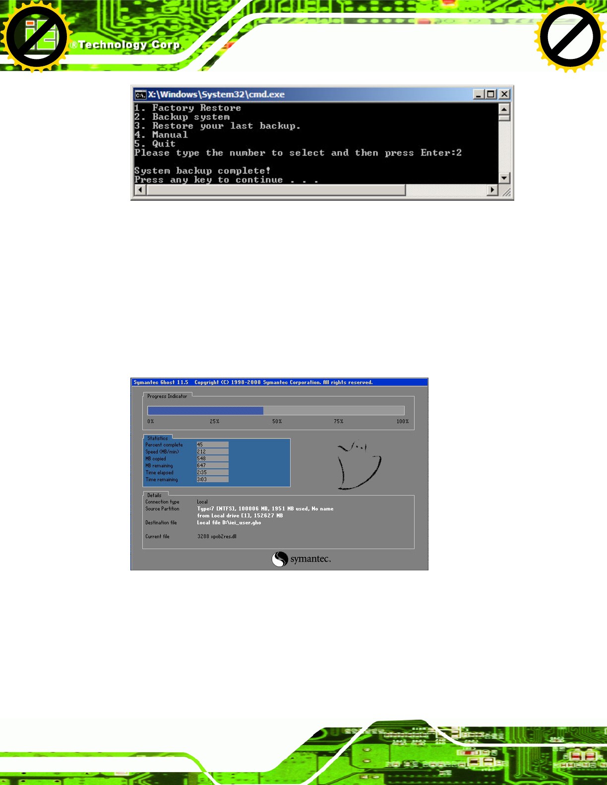
UPC-V312-D525 Panel PC
Page 136
Figure B-37: System Backup Complete Window
B.5.3 Restore Your Last Backup
To restore the last system backup, please follow the steps below.
Step 1: Type <3> and press <Enter> in the main menu.
Step 2: The Symantec Ghost window appears and starts to restore the last backup
image (iei_user.GHO).
Figure B-38: Restore Backup
Step 3: The screen shown in Figure B-39 appears when backup recovery is complete.
Press any key to reboot the system.
Click to buy NOW!
P
D
F
-
X
C
h
a
n
g
e
V
i
e
w
e
r
w
w
w
.
d
o
c
u
-
t
r
a
c
k
.
c
o
m
Click to buy NOW!
P
D
F
-
X
C
h
a
n
g
e
V
i
e
w
e
r
w
w
w
.
d
o
c
u
-
t
r
a
c
k
.
c
o
m
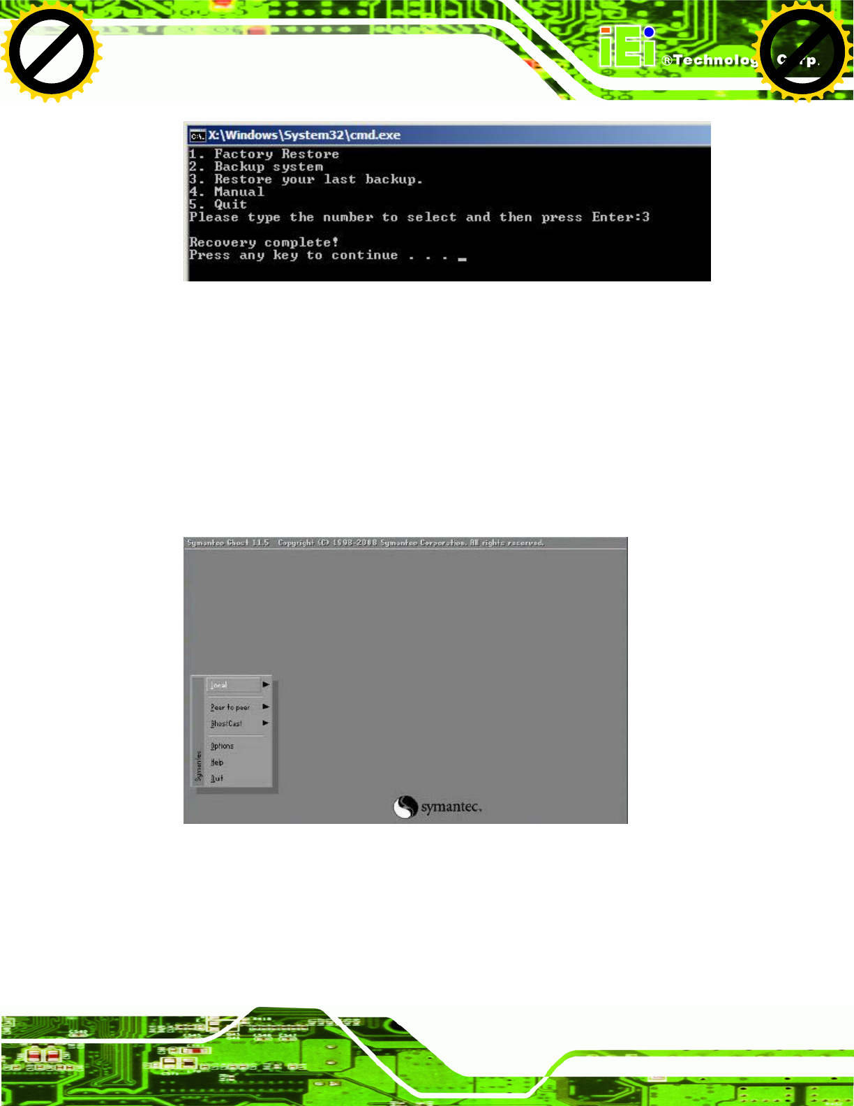
UPC-V312-D525 Panel PC
Page 137
Figure B-39: Restore System Backup Complete Window
B.5.4 Manual
To restore the last system backup, please follow the steps below.
Step 1: Type <4> and press <Enter> in the main menu.
Step 2: The Symantec Ghost window appears. Use the Ghost program to backup or
recover the system manually.
Figure B-40: Symantec Ghost Window
Step 3: When backup or recovery is completed, press any key to reboot the system.
Step 0:
Click to buy NOW!
P
D
F
-
X
C
h
a
n
g
e
V
i
e
w
e
r
w
w
w
.
d
o
c
u
-
t
r
a
c
k
.
c
o
m
Click to buy NOW!
P
D
F
-
X
C
h
a
n
g
e
V
i
e
w
e
r
w
w
w
.
d
o
c
u
-
t
r
a
c
k
.
c
o
m
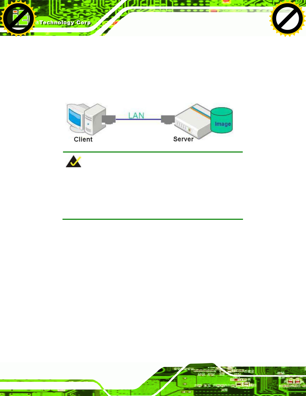
UPC-V312-D525 Panel PC
Page 138
B.6 Restore Systems from a Linux Server through LAN
The One Key Recovery allows a client system to automatically restore to a factory default
image saved in a Linux system (the server) through LAN connectivity after encountering a
Blue Screen of Death (BSoD) or a hang for around 10 minutes. To be able to use this
function, the client system and the Linux system MUST reside in the same domain.
NOTE:
The supported client OS includes:
Windows 2000 Windows 7
Windows XP Windows CE
Windows Vista Windows XP Embedded
Prior to restoring client systems from a Linux server, a few setup procedures are required.
Step 1: Configure DHCP server settings
Step 2: Configure TFTP settings
Step 3: Configure One Key Recovery server settings
Step 4: Start DHCP, TFTP and HTTP
Step 5: Create a shared directory
Step 6: Setup a client system for auto recovery
The detailed descriptions are described in the following sections. In this document, two
types of Linux OS are used as examples to explain the configuration process – CentOS
5.5 (Kernel 2.6.18) and Debian 5.0.7 (Kernel 2.6.26).
Click to buy NOW!
P
D
F
-
X
C
h
a
n
g
e
V
i
e
w
e
r
w
w
w
.
d
o
c
u
-
t
r
a
c
k
.
c
o
m
Click to buy NOW!
P
D
F
-
X
C
h
a
n
g
e
V
i
e
w
e
r
w
w
w
.
d
o
c
u
-
t
r
a
c
k
.
c
o
m
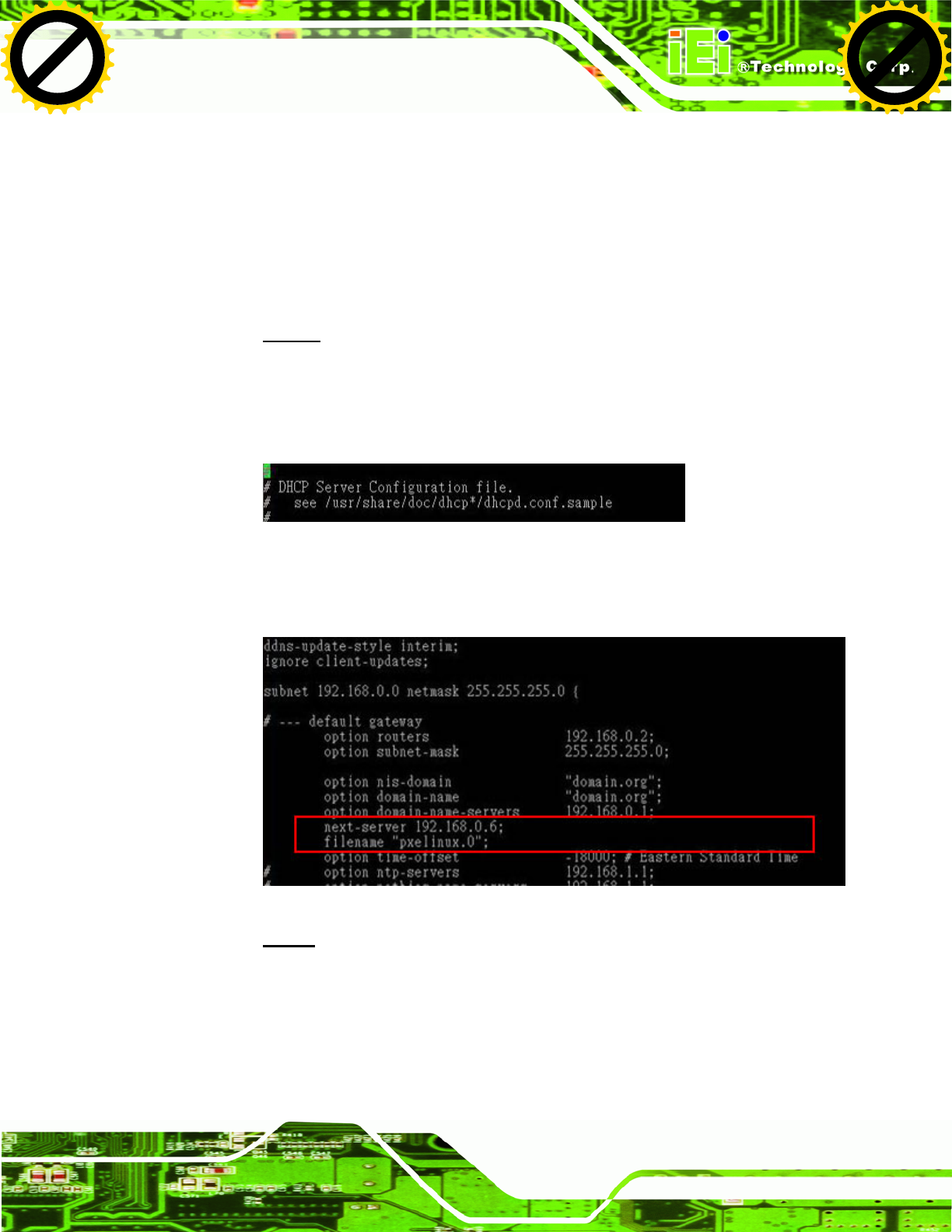
UPC-V312-D525 Panel PC
Page 139
B.6.1 Configure DHCP Server Settings
Step 1: Install the DHCP
#yum install dhcp (CentOS, commands marked in red)
#apt-get install dhcp3-server (Debian, commands marked in blue)
Step 2: Confirm the operating system default settings: dhcpd.conf.
CentOS
Use the following command to show the DHCP server sample location:
#vi /etc/dhcpd.conf
The DHCP server sample location is shown as below:
Use the following command to copy the DHCP server sample to etc/dhcpd.conf:
#cp /usr/share/doc/dhcp-3.0.5/dhcpd.conf.sample /etc/dhcpd.conf
#vi /etc/dhcpd.conf
Debian
#vi /etc/dhcpd.conf
Edit “/etc/dhcpd.conf” for your environment. For example, add
next-server PXE server IP address;
Click to buy NOW!
P
D
F
-
X
C
h
a
n
g
e
V
i
e
w
e
r
w
w
w
.
d
o
c
u
-
t
r
a
c
k
.
c
o
m
Click to buy NOW!
P
D
F
-
X
C
h
a
n
g
e
V
i
e
w
e
r
w
w
w
.
d
o
c
u
-
t
r
a
c
k
.
c
o
m
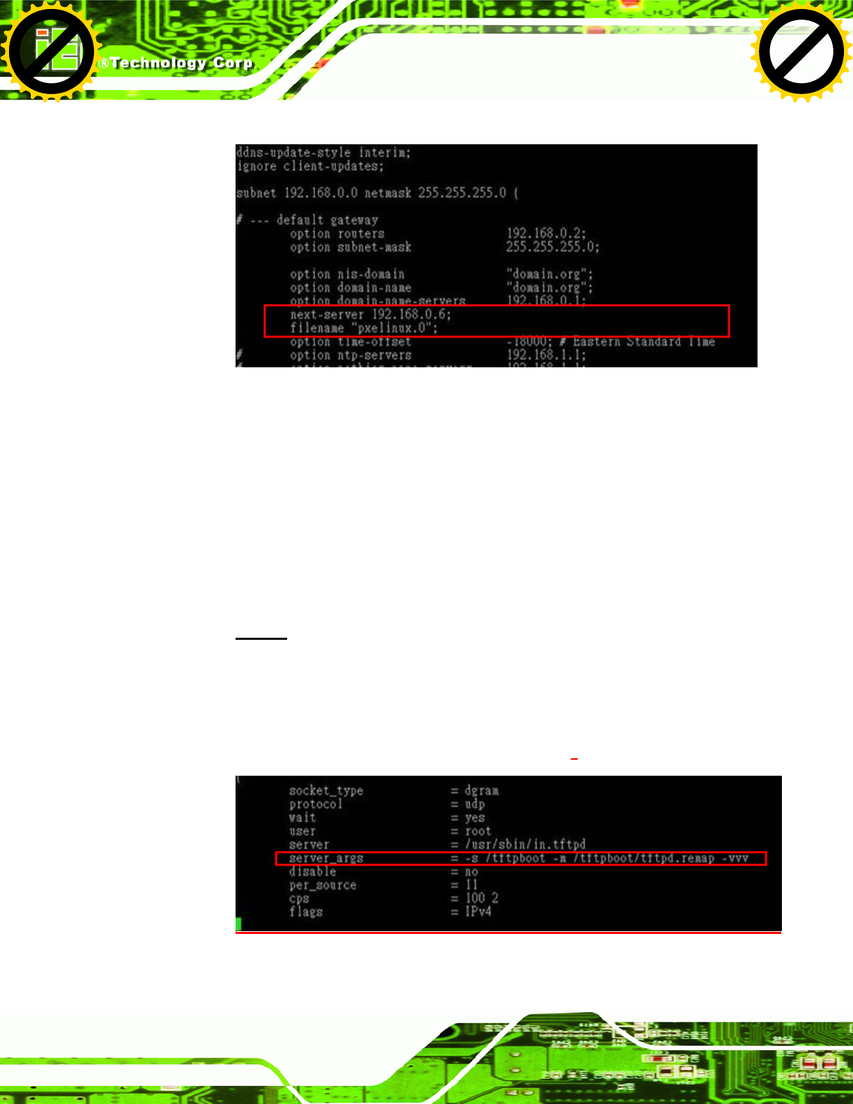
UPC-V312-D525 Panel PC
Page 140
filename “pxelinux.0”;
B.6.2 Configure TFTP Settings
Step 1: Install the tftp, httpd and syslinux.
#yum install tftp-server httpd syslinux (CentOS)
#apt-get install tftpd-hpa xinetd syslinux (Debian)
Step 2: Enable the TFTP server by editing the “/etc/xinetd.d/tftp” file and make it use the
remap file. The “-vvv” is optional but it could definitely help on getting more
information while running the remap file. For example:
CentOS
#vi /etc/xinetd.d/tftp
Modify:
disable = no
server_args = -s /tftpboot –m /tftpboot/tftpd.remap -vvv
Click to buy NOW!
P
D
F
-
X
C
h
a
n
g
e
V
i
e
w
e
r
w
w
w
.
d
o
c
u
-
t
r
a
c
k
.
c
o
m
Click to buy NOW!
P
D
F
-
X
C
h
a
n
g
e
V
i
e
w
e
r
w
w
w
.
d
o
c
u
-
t
r
a
c
k
.
c
o
m
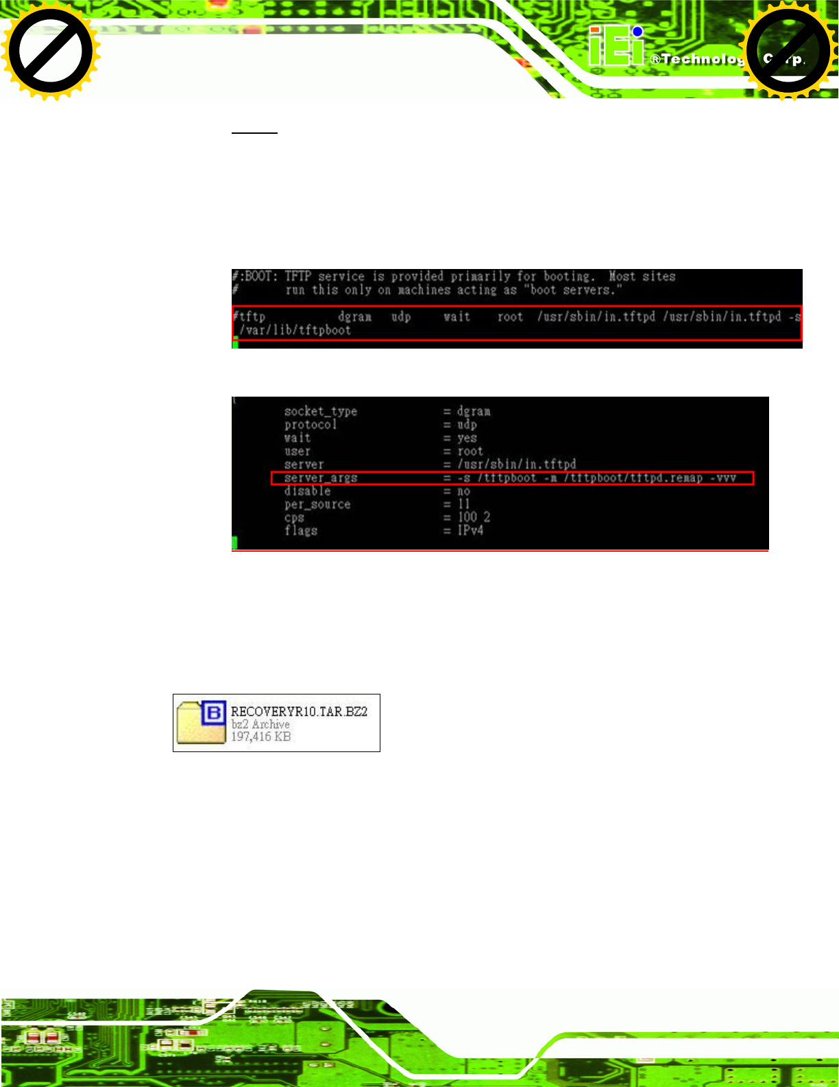
UPC-V312-D525 Panel PC
Page 141
Debian
Replace the TFTP settings from “inetd” to “xinetd” and annotate the “inetd” by
adding “#”.
#vi /etc/inetd.conf
Modify: #tftp dgram udp wait root /usr/sbin....... (as shown below)
#vi /etc/xinetd.d/tftp
B.6.3 Configure One Key Recovery Server Settings
Step 1: Copy the Utility/RECOVERYR10.TAR.BZ2 package from the One Key
Recovery CD to the system (server side).
Step 2: Extract the recovery package to /.
#cp RecoveryR10.tar.bz2 /
#cd /
#tar –xvjf RecoveryR10.tar.bz2
Step 3: Copy “pxelinux.0” from “syslinux” and install to “/tftboot”.
#cp /usr/lib/syslinux/pxelinux.0 /tftpboot/
Click to buy NOW!
P
D
F
-
X
C
h
a
n
g
e
V
i
e
w
e
r
w
w
w
.
d
o
c
u
-
t
r
a
c
k
.
c
o
m
Click to buy NOW!
P
D
F
-
X
C
h
a
n
g
e
V
i
e
w
e
r
w
w
w
.
d
o
c
u
-
t
r
a
c
k
.
c
o
m

UPC-V312-D525 Panel PC
Page 142
B.6.4 Start the DHCP, TFTP and HTTP
Start the DHCP, TFTP and HTTP. For example:
CentOS
#service xinetd restart
#service httpd restart
#service dhcpd restart
Debian
#/etc/init.d/xinetd reload
#/etc/init.d/xinetd restart
#/etc/init.d/dhcp3-server restart
B.6.5 Create Shared Directory
Step 1: Install the samba.
#yum install samba
Step 2: Create a shared directory for the factory default image.
#mkdir /share
#cd /share
#mkdir /image
#cp iei.gho /image
WARNING:
The file name of the factory default image must be iei.gho.
Step 3: Confirm the operating system default settings: smb.conf.
#vi /etc/samba/smb.conf
Click to buy NOW!
P
D
F
-
X
C
h
a
n
g
e
V
i
e
w
e
r
w
w
w
.
d
o
c
u
-
t
r
a
c
k
.
c
o
m
Click to buy NOW!
P
D
F
-
X
C
h
a
n
g
e
V
i
e
w
e
r
w
w
w
.
d
o
c
u
-
t
r
a
c
k
.
c
o
m
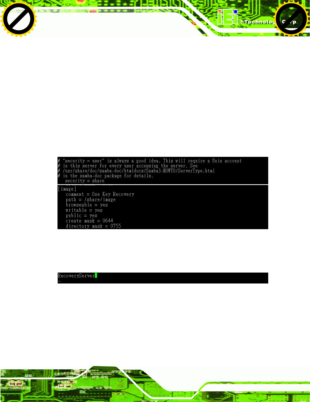
UPC-V312-D525 Panel PC
Page 143
Modify:
[image]
comment = One Key Recovery
path = /share/image
browseable = yes
writable = yes
public = yes
create mask = 0644
directory mask = 0755
Step 4: Edit “/etc/samba/smb.conf” for your environment. For example:
Step 5: Modify the hostname
#vi /etc/hostname
Modify: RecoveryServer
B.6.6 Setup a Client System for Auto Recovery
Step 1: Configure the following BIOS options of the client system.
Advanced → iEi Feature → Auto Recovery Function → Enabled
Advanced → iEi Feature → Recover from PXE → Enabled
Boot → Launch PXE OpROM → Enabled
Click to buy NOW!
P
D
F
-
X
C
h
a
n
g
e
V
i
e
w
e
r
w
w
w
.
d
o
c
u
-
t
r
a
c
k
.
c
o
m
Click to buy NOW!
P
D
F
-
X
C
h
a
n
g
e
V
i
e
w
e
r
w
w
w
.
d
o
c
u
-
t
r
a
c
k
.
c
o
m
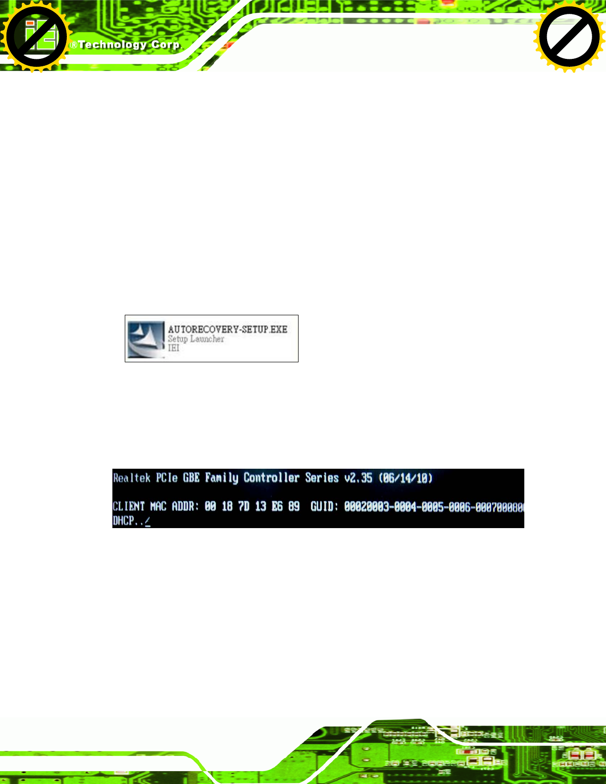
UPC-V312-D525 Panel PC
Page 144
Step 2: Continue to configure the Boot Option Priorities BIOS option of the client
system:
Boot Option #1 Æ remain the default setting to boot from the original OS.
Boot Option #2 Æ select the boot from LAN option.
Step 3: Save changes and exit BIOS menu.
Exit Æ Save Changes and Exit
Step 4: Install the auto recovery utility into the system by double clicking the
Utility/AUTORECOVERY-SETUP.exe in the One Key Recovery CD. This utility
MUST be installed in the system, otherwise, the system will automatically
restore from the factory default image every ten (10) minutes.
Step 5: Restart the client system from LAN. If the system encounters a Blue Screen of
Death (BSoD) or a hang for around 10 minutes, it will automatically restore from
the factory default image. The following screens will show when the system
starts auto recovering.
Click to buy NOW!
P
D
F
-
X
C
h
a
n
g
e
V
i
e
w
e
r
w
w
w
.
d
o
c
u
-
t
r
a
c
k
.
c
o
m
Click to buy NOW!
P
D
F
-
X
C
h
a
n
g
e
V
i
e
w
e
r
w
w
w
.
d
o
c
u
-
t
r
a
c
k
.
c
o
m
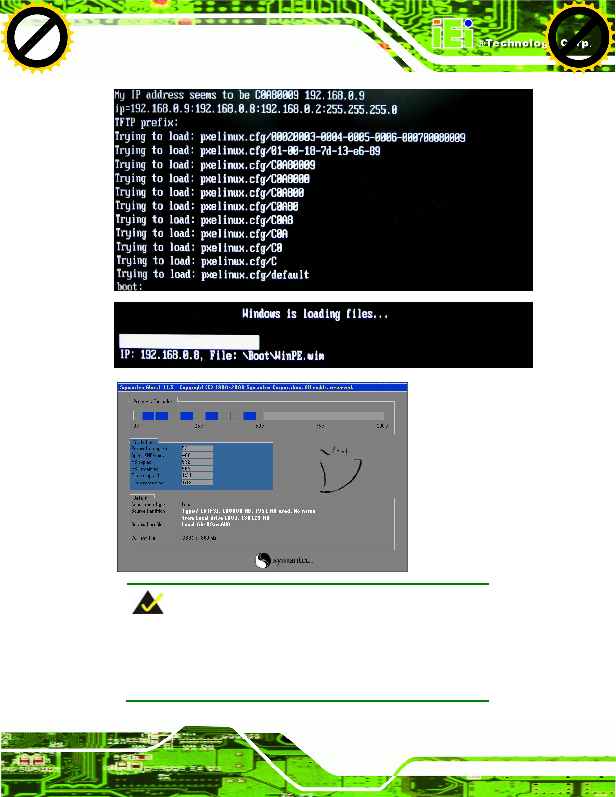
UPC-V312-D525 Panel PC
Page 145
NOTE:
A firewall or a SELinux is not in use in the whole setup process. If there
is a firewall or a SELinux protecting the system, modify the
configuration information to accommodate them.
Click to buy NOW!
P
D
F
-
X
C
h
a
n
g
e
V
i
e
w
e
r
w
w
w
.
d
o
c
u
-
t
r
a
c
k
.
c
o
m
Click to buy NOW!
P
D
F
-
X
C
h
a
n
g
e
V
i
e
w
e
r
w
w
w
.
d
o
c
u
-
t
r
a
c
k
.
c
o
m
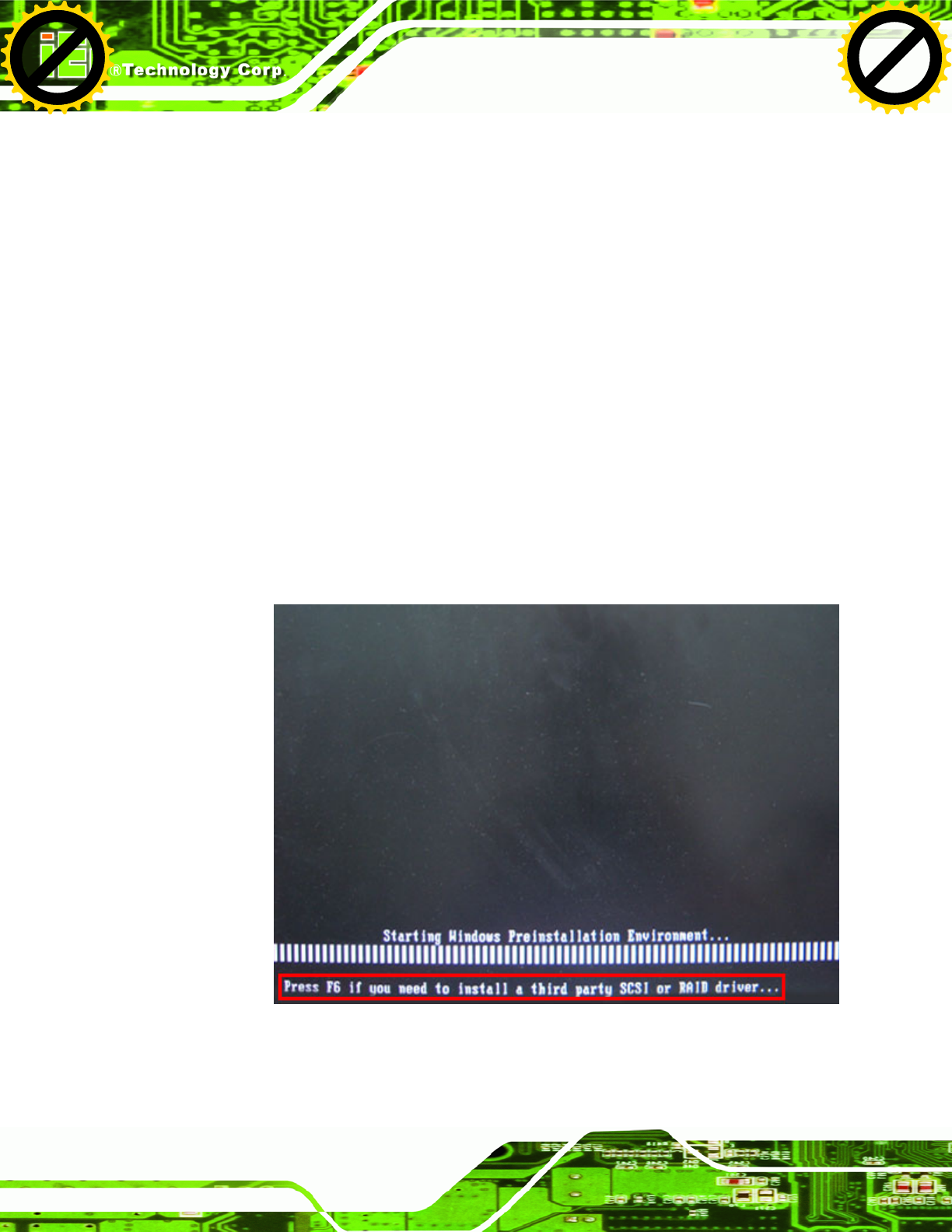
UPC-V312-D525 Panel PC
Page 146
B.7 Other Information
B.7.1 Using AHCI Mode or ALi M5283 / VIA VT6421A Controller
When the system uses AHCI mode or some specific SATA controllers such as ALi M5283
or VIA VT6421A, the SATA RAID/AHCI driver must be installed before using one key
recovery. Please follow the steps below to install the SATA RAID/AHCI driver.
Step 1: Copy the SATA RAID/AHCI driver to a floppy disk and insert the floppy disk into
a USB floppy disk drive. The SATA RAID/AHCI driver must be especially
designed for the on-board SATA controller.
Step 2: Connect the USB floppy disk drive to the system.
Step 3: Insert the One Key Recovery CD into the system and boot the system from the
CD.
Step 4: When launching the recovery tool, press <F6>.
Click to buy NOW!
P
D
F
-
X
C
h
a
n
g
e
V
i
e
w
e
r
w
w
w
.
d
o
c
u
-
t
r
a
c
k
.
c
o
m
Click to buy NOW!
P
D
F
-
X
C
h
a
n
g
e
V
i
e
w
e
r
w
w
w
.
d
o
c
u
-
t
r
a
c
k
.
c
o
m

UPC-V312-D525 Panel PC
Page 147
Step 5: When the following window appears, press <S> to select “Specify Additional
Device”.
Step 6: In the following window, select a SATA controller mode used in the system. Then
press <Enter>. The user can now start using the SATA HDD.
Click to buy NOW!
P
D
F
-
X
C
h
a
n
g
e
V
i
e
w
e
r
w
w
w
.
d
o
c
u
-
t
r
a
c
k
.
c
o
m
Click to buy NOW!
P
D
F
-
X
C
h
a
n
g
e
V
i
e
w
e
r
w
w
w
.
d
o
c
u
-
t
r
a
c
k
.
c
o
m

UPC-V312-D525 Panel PC
Page 148
Step 7: After pressing <Enter>, the system will get into the recovery tool setup menu.
Continue to follow the setup procedure from Step 4 in Section B.2.2 Create
Partitions to finish the whole setup process. Step 0:
B.7.2 System Memory Requirement
To be able to access the recovery tool by pressing <F3> while booting up the system,
please make sure to have enough system memory. The minimum memory requirement is
listed below.
Using Award BIOS: 128 MB system memory
Using AMI BIOS: 512 MB system memory.
Click to buy NOW!
P
D
F
-
X
C
h
a
n
g
e
V
i
e
w
e
r
w
w
w
.
d
o
c
u
-
t
r
a
c
k
.
c
o
m
Click to buy NOW!
P
D
F
-
X
C
h
a
n
g
e
V
i
e
w
e
r
w
w
w
.
d
o
c
u
-
t
r
a
c
k
.
c
o
m


UPC-V312-D525 Panel PC
Page 150
WARNING:
The precautions outlined in this chapter should be strictly followed.
Failure to follow these precautions may result in permanent damage to
the EP series.
C.1 Safety Precautions
Please follow the safety precautions outlined in the sections that follow:
C.1.1 General Safety Precautions
Please ensure the following safety precautions are adhered to at all times.
Follow the electrostatic precautions outlined below whenever the EP
series is opened.
Make sure the power is turned off and the power cord is disconnected
whenever the EP series is being installed, moved or modified.
Do not apply voltage levels that exceed the specified voltage range.
Doing so may cause fire and/or an electrical shock.
Electric shocks can occur if the EP series chassis is opened when the EP
series is running.
Do not drop or insert any objects into the ventilation openings of the EP
series.
If considerable amounts of dust, water, or fluids enter the EP series, turn
off the power supply immediately, unplug the power cord, and contact the EP
series vendor.
DO NOT:
o Drop the EP series against a hard surface.
o Strike or exert excessive force onto the LCD panel.
o Touch any of the LCD panels with a sharp object
o In a site where the ambient temperature exceeds the rated temperature
Click to buy NOW!
P
D
F
-
X
C
h
a
n
g
e
V
i
e
w
e
r
w
w
w
.
d
o
c
u
-
t
r
a
c
k
.
c
o
m
Click to buy NOW!
P
D
F
-
X
C
h
a
n
g
e
V
i
e
w
e
r
w
w
w
.
d
o
c
u
-
t
r
a
c
k
.
c
o
m
UPC-V312-D525 Panel PC
Page 151
C.1.2 Anti-static Precautions
WARNING:
Failure to take ESD precautions during the installation of the EP series
may result in permanent damage to the EP series and severe injury to
the user.
Electrostatic discharge (ESD) can cause serious damage to electronic components,
including the EP series. Dry climates are especially susceptible to ESD. It is therefore
critical that whenever the EP series is opened and any of the electrical components are
handled, the following anti-static precautions are strictly adhered to.
Wear an anti-static wristband: Wearing a simple anti-static wristband can
help to prevent ESD from damaging any electrical component.
Self-grounding: Before handling any electrical component, touch any
grounded conducting material. During the time the electrical component is
handled, frequently touch any conducting materials that are connected to the
ground.
Use an anti-static pad: When configuring or working with an electrical
component, place it on an antic-static pad. This reduces the possibility of ESD
damage.
Only handle the edges of the electrical component: When handling the
electrical component, hold the electrical component by its edges.
C.1.3 Product Disposal
CAUTION:
Risk of explosion if battery is replaced by and incorrect type. Only certified
engineers should replace the on-board battery.
Dispose of used batteries according to instructions and local regulations.
Click to buy NOW!
P
D
F
-
X
C
h
a
n
g
e
V
i
e
w
e
r
w
w
w
.
d
o
c
u
-
t
r
a
c
k
.
c
o
m
Click to buy NOW!
P
D
F
-
X
C
h
a
n
g
e
V
i
e
w
e
r
w
w
w
.
d
o
c
u
-
t
r
a
c
k
.
c
o
m
UPC-V312-D525 Panel PC
Page 152
Outside the European Union - If you wish to dispose of used electrical and
electronic products outside the European Union, please contact your local
authority so as to comply with the correct disposal method.
Within the European Union:
EU-wide legislation, as implemented in each Member State, requires that
waste electrical and electronic products carrying the mark (left) must be
disposed of separately from normal household waste. This includes
monitors and electrical accessories, such as signal cables or power cords.
When you need to dispose of your display products, please follow the
guidance of your local authority, or ask the shop where you purchased the product. The
mark on electrical and electronic products only applies to the current European Union
Member States.
Please follow the national guidelines for electrical and electronic product disposal.
C.2 Maintenance and Cleaning Precautions
When maintaining or cleaning the EP series, please follow the guidelines below.
C.2.1 Maintenance and Cleaning
Prior to cleaning any part or component of the EP series, please read the details below.
Except for the LCD panel, never spray or squirt liquids directly onto any other
components. To clean the LCD panel, gently wipe it with a piece of soft dry
cloth or a slightly moistened cloth.
The interior of the EP series does not require cleaning. Keep fluids away from
the EP series interior.
Be cautious of all small removable components when vacuuming the EP
series.
Turn the EP series off before cleaning the EP series.
Never drop any objects or liquids through the openings of the EP series.
Be cautious of any possible allergic reactions to solvents or chemicals used
when cleaning the EP series.
Avoid eating, drinking and smoking within vicinity of the EP series.
Click to buy NOW!
P
D
F
-
X
C
h
a
n
g
e
V
i
e
w
e
r
w
w
w
.
d
o
c
u
-
t
r
a
c
k
.
c
o
m
Click to buy NOW!
P
D
F
-
X
C
h
a
n
g
e
V
i
e
w
e
r
w
w
w
.
d
o
c
u
-
t
r
a
c
k
.
c
o
m

UPC-V312-D525 Panel PC
Page 153
C.2.2 Cleaning Tools
Some components in the EP series may only be cleaned using a product specifically
designed for the purpose. In such case, the product will be explicitly mentioned in the
cleaning tips. Below is a list of items to use when cleaning the EP series.
Cloth – Although paper towels or tissues can be used, a soft, clean piece of
cloth is recommended when cleaning the EP series.
Water or rubbing alcohol – A cloth moistened with water or rubbing alcohol
can be used to clean the EP series.
Using solvents – The use of solvents is not recommended when cleaning the
EP series as they may damage the plastic parts.
Vacuum cleaner – Using a vacuum specifically designed for computers is
one of the best methods of cleaning the EP series. Dust and dirt can restrict
the airflow in the EP series and cause its circuitry to corrode.
Cotton swabs - Cotton swaps moistened with rubbing alcohol or water are
excellent tools for wiping hard to reach areas.
Foam swabs - Whenever possible, it is best to use lint free swabs such as
foam swabs for cleaning.
Click to buy NOW!
P
D
F
-
X
C
h
a
n
g
e
V
i
e
w
e
r
w
w
w
.
d
o
c
u
-
t
r
a
c
k
.
c
o
m
Click to buy NOW!
P
D
F
-
X
C
h
a
n
g
e
V
i
e
w
e
r
w
w
w
.
d
o
c
u
-
t
r
a
c
k
.
c
o
m

UPC-V312-D525 Panel PC
Page 155
NOTE:
The following discussion applies to DOS environment. IEI support is
contacted or the IEI website visited for specific drivers for more
sophisticated operating systems, e.g., Windows and Linux.
The Watchdog Timer is provided to ensure that standalone systems can always recover
from catastrophic conditions that cause the CPU to crash. This condition may have
occurred by external EMI or a software bug. When the CPU stops working correctly,
Watchdog Timer either performs a hardware reset (cold boot) or a Non-Maskable Interrupt
(NMI) to bring the system back to a known state.
A BIOS function call (INT 15H) is used to control the Watchdog Timer:
INT 15H:
AH – 6FH Sub-function:
AL – 2: Sets the Watchdog Timer’s period.
BL: Time-out value (Its unit-second is dependent on the item “Watchdog
Timer unit select” in CMOS setup).
Table D-1: AH-6FH Sub-function
Call sub-function 2 to set the time-out period of Watchdog Timer first. If the time-out value
is not zero, the Watchdog Timer starts counting down. While the timer value reaches zero,
the system resets. To ensure that this reset condition does not occur, calling sub-function
2 must periodically refresh the Watchdog Timer. However, the Watchdog timer is disabled
if the time-out value is set to zero.
A tolerance of at least 10% must be maintained to avoid unknown routines within the
operating system (DOS), such as disk I/O that can be very time-consuming.
Click to buy NOW!
P
D
F
-
X
C
h
a
n
g
e
V
i
e
w
e
r
w
w
w
.
d
o
c
u
-
t
r
a
c
k
.
c
o
m
Click to buy NOW!
P
D
F
-
X
C
h
a
n
g
e
V
i
e
w
e
r
w
w
w
.
d
o
c
u
-
t
r
a
c
k
.
c
o
m

UPC-V312-D525 Panel PC
Page 156
NOTE:
When exiting a program it is necessary to disable the Watchdog Timer,
otherwise the system resets.
Example program:
; INITIAL TIMER PERIOD COUNTER
;
W_LOOP:
MOV AX, 6F02H ;setting the time-out value
MOV BX, 05 ;time-out value is 5 seconds
INT 15H
;
; ADD THE APPLICATION PROGRAM HERE
;
CMP EXIT_AP, 1 ;is the application over?
JNE W_LOOP ;No, restart the application
MOV AX, 6F02H ;disable Watchdog Timer
MOV BX, 0 ;
INT 15H
;
; EXIT ;
Click to buy NOW!
P
D
F
-
X
C
h
a
n
g
e
V
i
e
w
e
r
w
w
w
.
d
o
c
u
-
t
r
a
c
k
.
c
o
m
Click to buy NOW!
P
D
F
-
X
C
h
a
n
g
e
V
i
e
w
e
r
w
w
w
.
d
o
c
u
-
t
r
a
c
k
.
c
o
m


UPC-V312-D525 Panel PC
Page 158
E.1 Hazardous Material Disclosure Table for IPB Products
Certified as RoHS Compliant Under 2002/95/EC Without Mercury
The details provided in this appendix are to ensure that the product is compliant with the
Peoples Republic of China (China) RoHS standards. The table below acknowledges the
presences of small quantities of certain materials in the product, and is applicable to China
RoHS only.
A label will be placed on each product to indicate the estimated “Environmentally Friendly
Use Period” (EFUP). This is an estimate of the number of years that these substances
would “not leak out or undergo abrupt change.” This product may contain replaceable
sub-assemblies/components which have a shorter EFUP such as batteries and lamps.
These components will be separately marked.
Please refer to the table on the next page.
Click to buy NOW!
P
D
F
-
X
C
h
a
n
g
e
V
i
e
w
e
r
w
w
w
.
d
o
c
u
-
t
r
a
c
k
.
c
o
m
Click to buy NOW!
P
D
F
-
X
C
h
a
n
g
e
V
i
e
w
e
r
w
w
w
.
d
o
c
u
-
t
r
a
c
k
.
c
o
m
UPC-V312-D525 Panel PC
Page 159
Toxic or Hazardous Substances and Elements Part Name
Lead
(Pb)
Mercury
(Hg)
Cadmium
(Cd)
Hexavalent
Chromium
(CR(VI))
Polybrominated
Biphenyls
(PBB)
Polybrominated
Diphenyl Ethers
(PBDE)
Housing X O O O O X
Display X
O O O O X
Printed Circuit
Board
X O O O O X
Metal Fasteners X O O O O O
Cable Assembly X O O O O X
Fan Assembly X O O O O X
Power Supply
Assemblies
X O O O O X
Battery O
O O O O O
O: This toxic or hazardous substance is contained in all of the homogeneous materials for the part is below
the limit requirement in SJ/T11363-2006
X: This toxic or hazardous substance is contained in at least one of the homogeneous materials for this part
is above the limit requirement in SJ/T11363-2006
Click to buy NOW!
P
D
F
-
X
C
h
a
n
g
e
V
i
e
w
e
r
w
w
w
.
d
o
c
u
-
t
r
a
c
k
.
c
o
m
Click to buy NOW!
P
D
F
-
X
C
h
a
n
g
e
V
i
e
w
e
r
w
w
w
.
d
o
c
u
-
t
r
a
c
k
.
c
o
m
UPC-V312-D525 Panel PC
Page 160
此附件旨在确保本产品符合中国 RoHS 标准。以下表格标示此产品中某有毒物质的含量符
合中国 RoHS 标准规定的限量要求。
本产品上会附有”环境友好使用期限”的标签,此期限是估算这些物质”不会有泄漏或突变”的
年限。本产品可能包含有较短的环境友好使用期限的可替换元件,像是电池或灯管,这些
元件将会单独标示出来。
有毒有害物质或元素
部件名称
铅
(Pb)
汞
(Hg)
镉
(Cd)
六价铬
(CR(VI))
多溴联苯
(PBB)
多溴二苯醚
(PBDE)
壳体 X O O O O X
显示 X O O O O X
印刷电路板 X O O O O X
金属螺帽 X O O O O O
电缆组装 X O O O O X
风扇组装 X O O O O X
电力供应组装 X O O O O X
电池 O O O O O O
O: 表示该有毒有害物质在该部件所有物质材料中的含量均在 SJ/T11363-2006 标准规定的限量要求以下。
X: 表示该有毒有害物质至少在该部件的某一均质材料中的含量超出 SJ/T11363-2006 标准规定的限量要求。
Click to buy NOW!
P
D
F
-
X
C
h
a
n
g
e
V
i
e
w
e
r
w
w
w
.
d
o
c
u
-
t
r
a
c
k
.
c
o
m
Click to buy NOW!
P
D
F
-
X
C
h
a
n
g
e
V
i
e
w
e
r
w
w
w
.
d
o
c
u
-
t
r
a
c
k
.
c
o
m