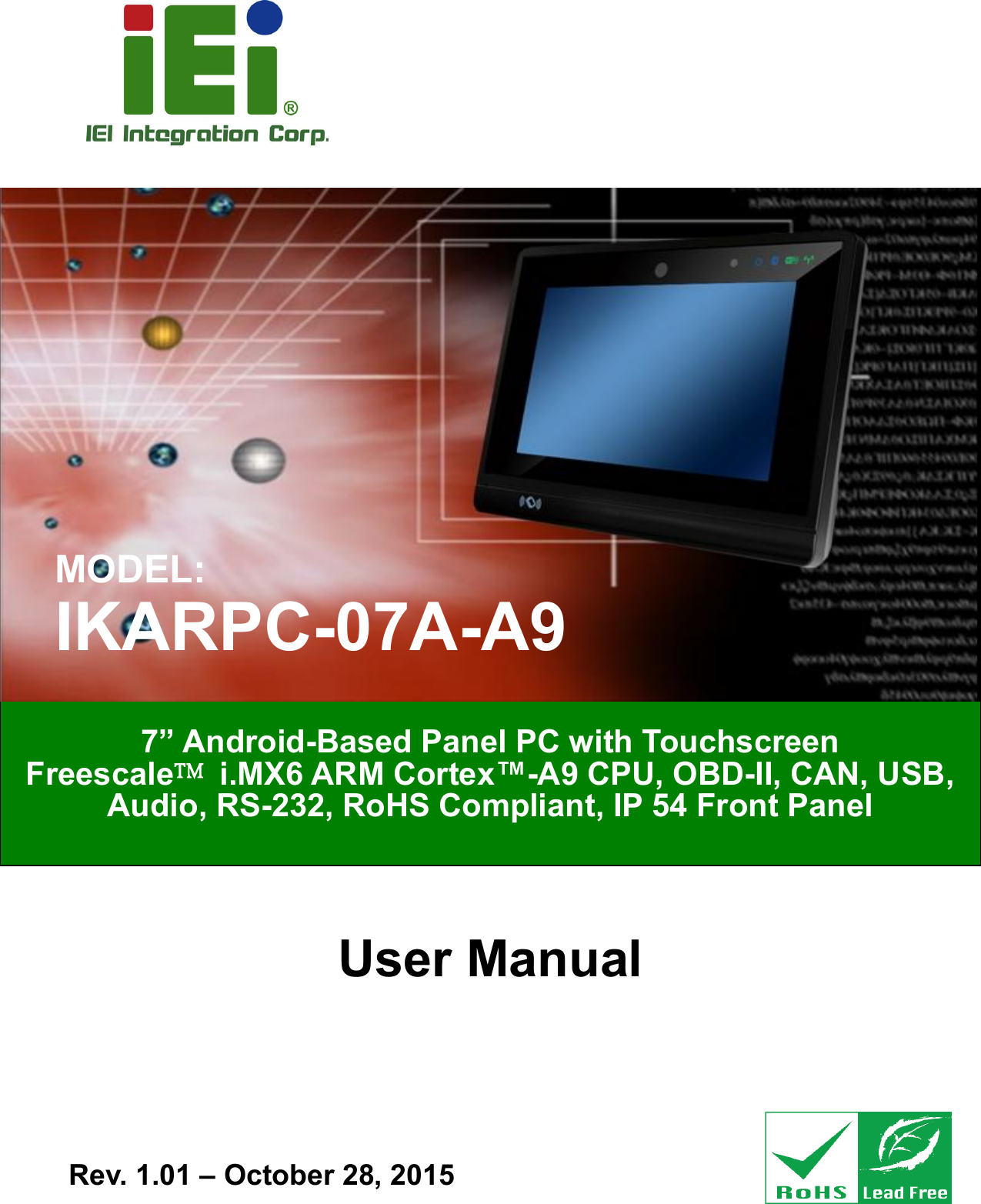
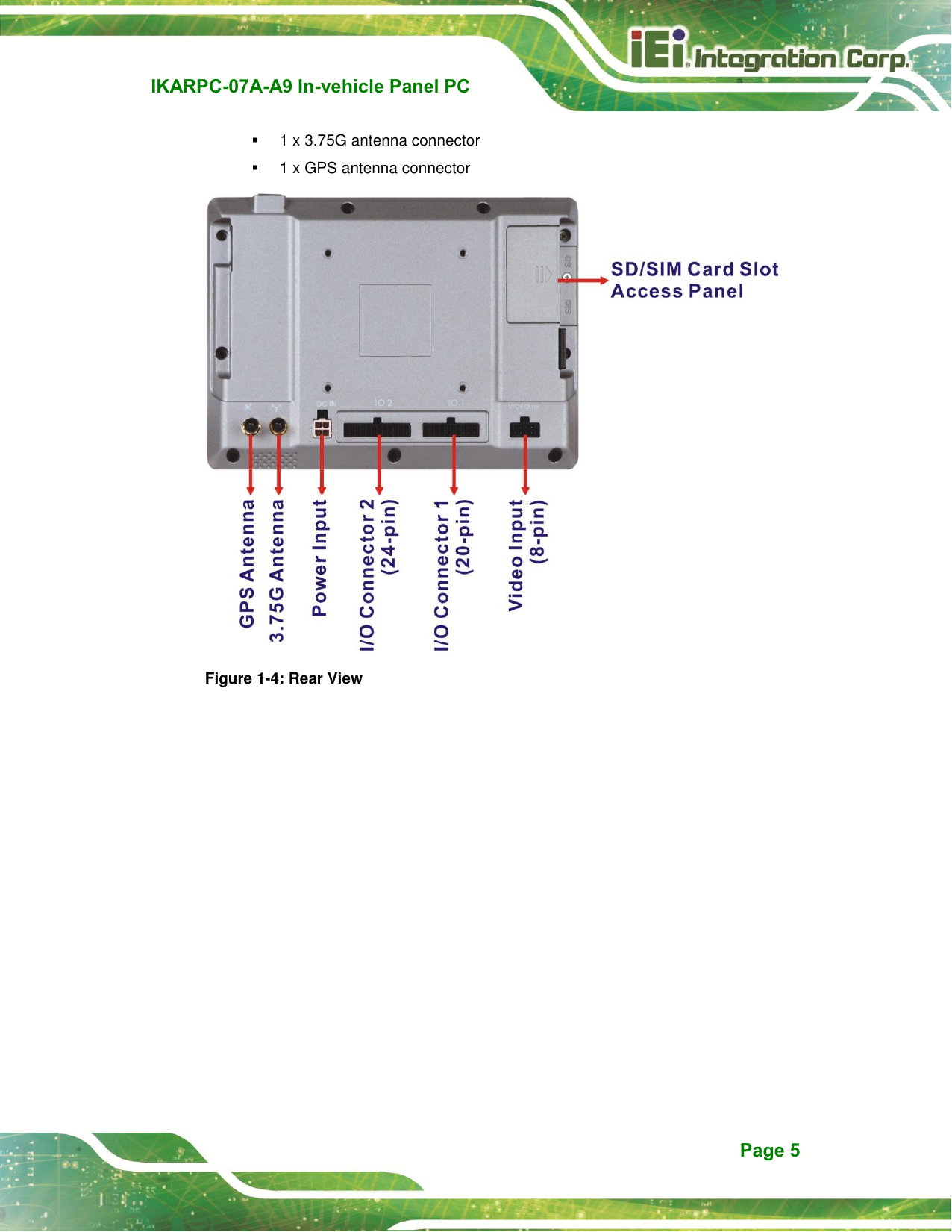
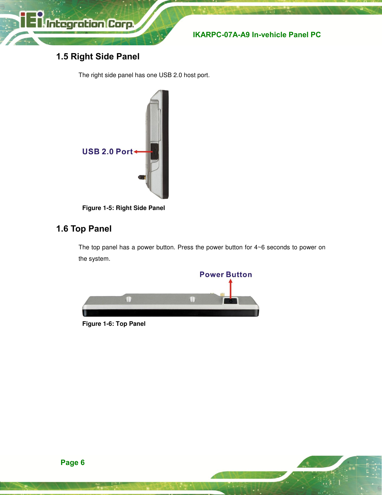
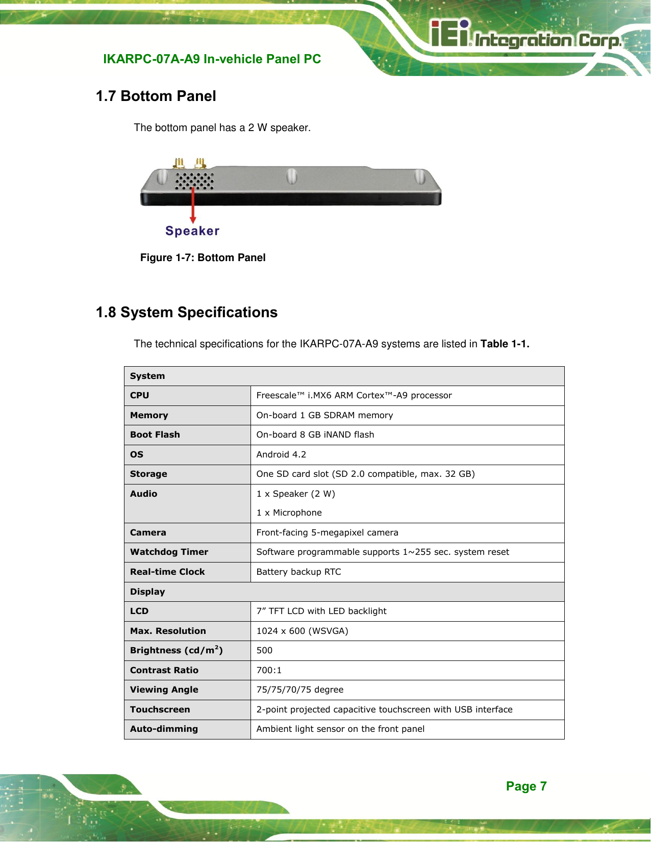
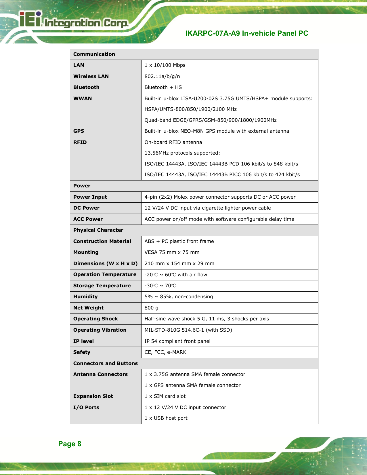
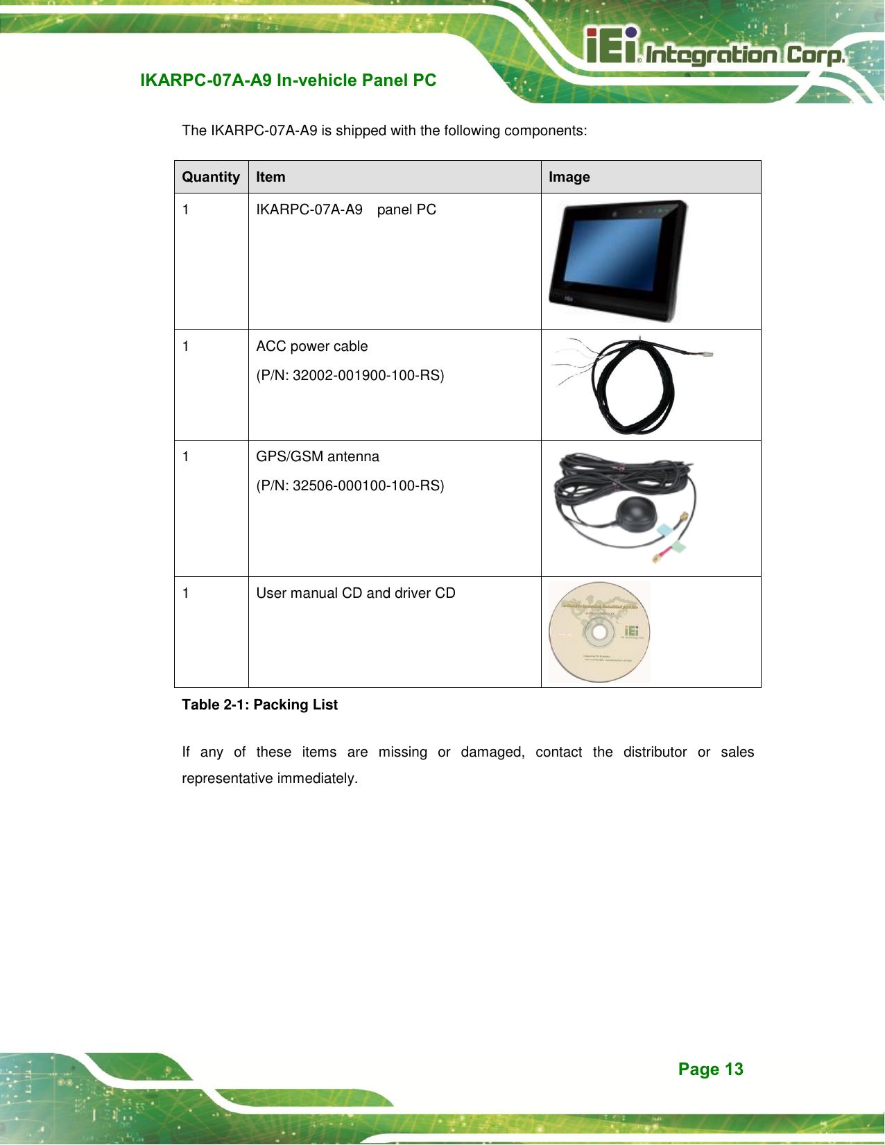
IEI Integration IKARPC07AA9 Panel PC User Manual IKARPC 07A A9 In vehicle Panel PC
IEI Integration Corp. Panel PC IKARPC 07A A9 In vehicle Panel PC
UserManual.wiki
>
IEI Integration
>
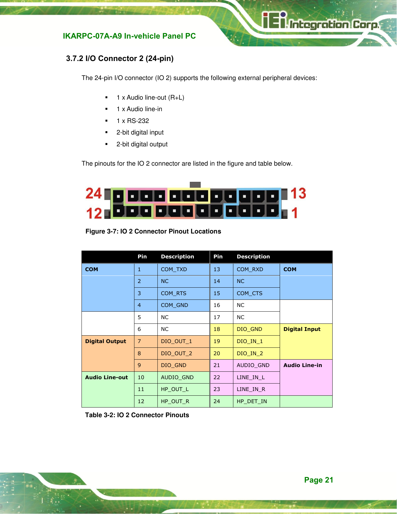
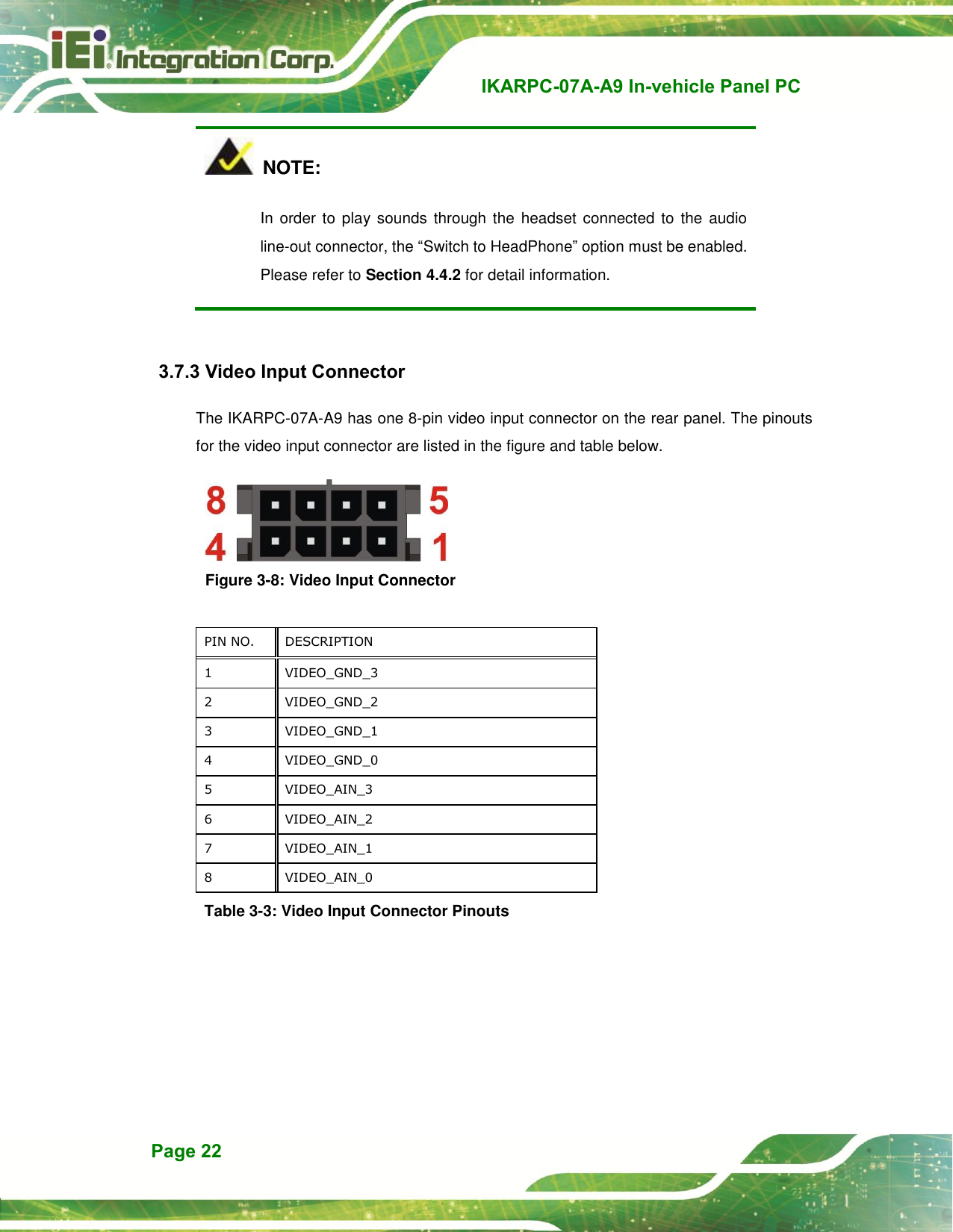
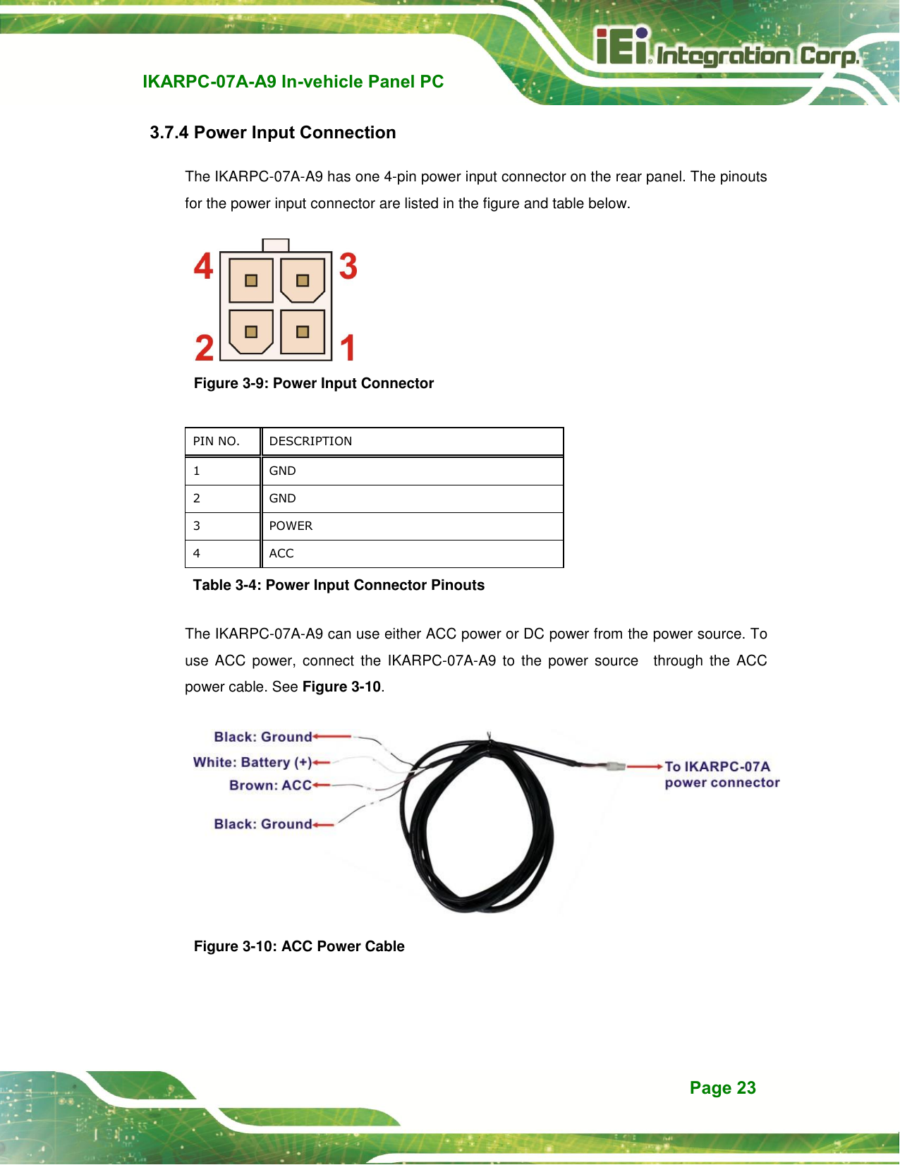
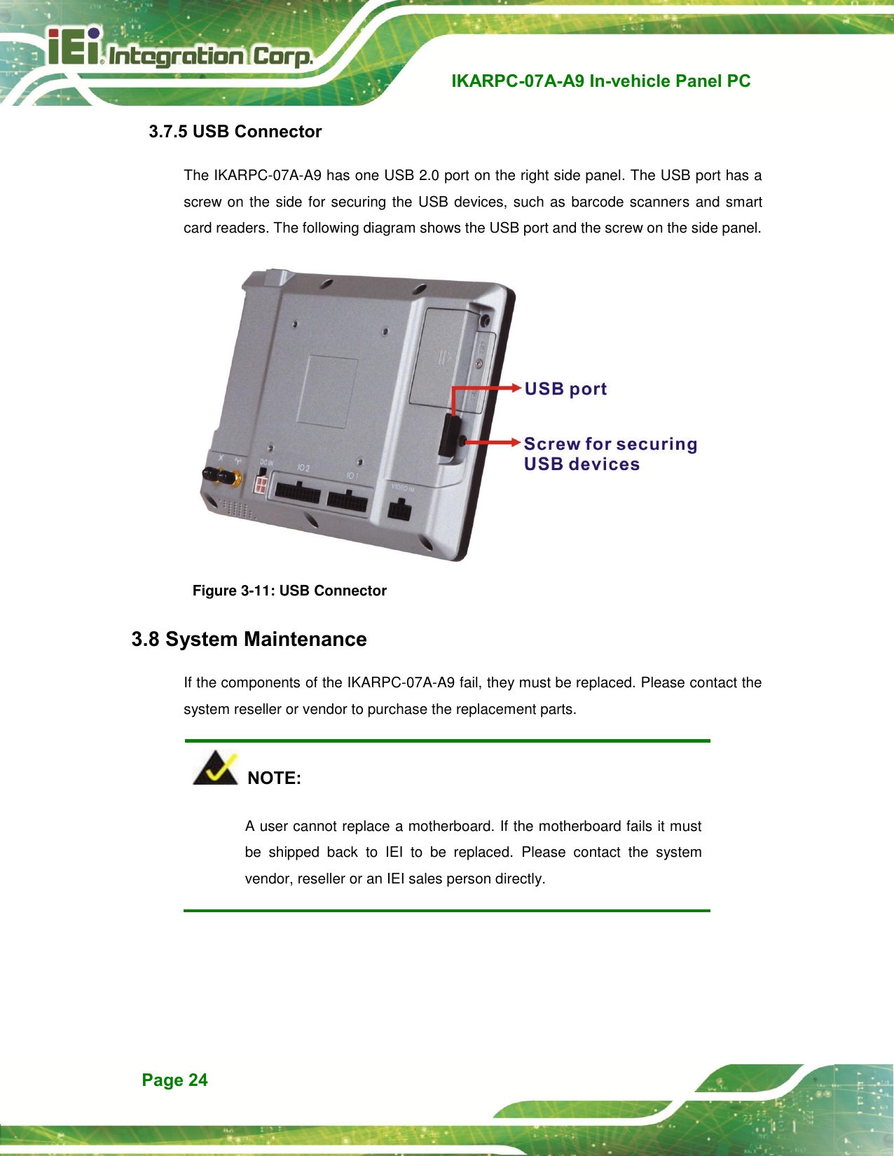
IKARPC07AA9 User Manual
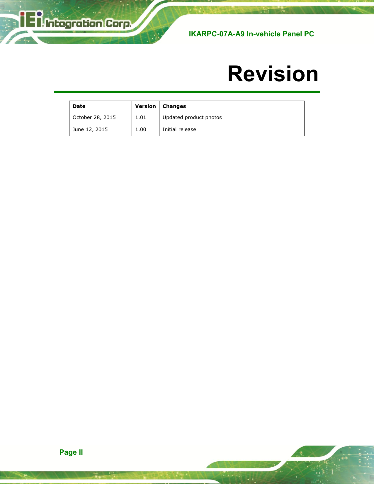
User Manual rev
Navigation menu
Upload a User Manual
Namespaces
Wiki Guide
HTML
PDF
Info
Views
User Manual
Discussion / Help
Navigation
![IKARPC-07A-A9 In-vehicle Panel PC Page 59 DECLARATION OF CONFORMITY This equipment is in conformity with the following EU directives: EMC Directive 2004/108/EC Low-Voltage Directive 2006/95/EC RoHS II Directive 2011/65/EU Ecodesign Directive 2009/125/EC If the user modifies and/or install other devices in the equipment, the CE conformity declaration may no longer apply. If this equipment has telecommunications functionality, it also complies with the requirements of the R&TTE Directive 1999/5/EC. English IEI Integration Corp declares that this equipment is in compliance with the essential requirements and other relevant provisions of Directive 1999/5/EC. Български [Bulgarian] IEI Integration Corp. декларира, че този оборудване е в съответствие със съществените изисквания и другите приложими правила на Директива 1999/5/ЕС. Česky [Czech] IEI Integration Corp tímto prohlašuje, že tento zařízení je ve shodě se základními požadavky a dalšími příslušnými ustanoveními směrnice 1999/5/ES. Dansk [Danish] IEI Integration Corp erklæ rer herved, at følgende udstyr overholder de væ sentlige krav og øvrige relevante krav i direktiv 1999/5/EF. Deutsch [German] IEI Integration Corp, erklärt dieses Gerät entspricht den grundlegenden Anforderungen und den weiteren entsprechenden Vorgaben der Richtlinie 1999/5/EU. Eesti [Estonian] IEI Integration Corp deklareerib seadme seadme vastavust direktiivi 1999/5/EÜ põhinõuetele ja nimetatud direktiivist tulenevatele teistele asjakohastele sätetele.](https://usermanual.wiki/IEI-Integration/IKARPC07AA9/User-Guide-3089626-Page-69.png)
![IKARPC-07A-A9 In-vehicle Panel PC Page 60 Español [Spanish] IEI Integration Corp declara que el equipo cumple con los requisitos esenciales y cualesquiera otras disposiciones aplicables o exigibles de la Directiva 1999/5/CE. Ελληνική [Greek] IEI Integration Corp ΔΗΛΩΝΕΙ ΟΣΙ ΕΞΟΠΛΙΜΟ ΤΜΜΟΡΦΩΝΕΣΑΙ ΠΡΟ ΣΙ ΟΤΙΩΔΕΙ ΑΠΑΙΣΗΕΙ ΚΑΙ ΣΙ ΛΟΙΠΕ ΥΕΣΙΚΕ ΔΙΑΣΑΞΕΙ ΣΗ ΟΔΗΓΙΑ 1999/5/ΕΚ. Français [French] IEI Integration Corp déclare que l'appareil est conforme aux exigences essentielles et aux autres dispositions pertinentes de la directive 1999/5/CE. Italiano [Italian] IEI Integration Corp dichiara che questo apparecchio è conforme ai requisiti essenziali ed alle altre disposizioni pertinenti stabilite dalla direttiva 1999/5/CE. Latviski [Latvian] IEI Integration Corp deklarē, ka iekārta atbilst būtiskajām prasībām un citiem ar to saistītajiem noteikumiem Direktīvas 1999/5/EK. Lietuvių [Lithuanian] IEI Integration Corp deklaruoja, kad šis įranga atitinka esminius reikalavimus ir kitas 1999/5/EB Direktyvos nuostatas. Nederlands [Dutch] IEI Integration Corp dat het toestel toestel in overeenstemming is met de essentiële eisen en de andere relevante bepalingen van richtlijn 1999/5/EG. Malti [Maltese] IEI Integration Corp jiddikjara li dan prodott jikkonforma mal-ħtiġijiet essenzjali u ma provvedimenti oħrajn relevanti li hemm fid-Dirrettiva 1999/5/EC. Magyar [Hungarian] IEI Integration Corp nyilatkozom, hogy a berendezés megfelel a vonatkozó alapvetõ követelményeknek és az 1999/5/EC irányelv egyéb elõírásainak. Polski [Polish] IEI Integration Corp oświadcza, że wyrobu jest zgodny z zasadniczymi wymogami oraz pozostałymi stosownymi postanowieniami Dyrektywy 1999/5/EC. Português [Portuguese] IEI Integration Corp declara que este equipamento está conforme com os requisitos essenciais e outras disposições da Directiva 1999/5/CE.](https://usermanual.wiki/IEI-Integration/IKARPC07AA9/User-Guide-3089626-Page-70.png)
![IKARPC-07A-A9 In-vehicle Panel PC Page 61 Româna [Romanian] IEI Integration Corp declară că acest echipament este in conformitate cu cerinţele esenţiale şi cu celelalte prevederi relevante ale Directivei 1999/5/CE. Slovensko [Slovenian] IEI Integration Corp izjavlja, da je ta opreme v skladu z bistvenimi zahtevami in ostalimi relevantnimi določili direktive 1999/5/ES. Slovensky [Slovak] IEI Integration Corp týmto vyhlasuje, že zariadenia spĺňa základné požiadavky a všetky príslušné ustanovenia Smernice 1999/5/ES. Suomi [Finnish] IEI Integration Corp vakuuttaa täten että laitteet on direktiivin 1999/5/EY oleellisten vaatimusten ja sitä koskevien direktiivin muiden ehtojen mukainen. Svenska [Swedish] IEI Integration Corp förklarar att denna utrustningstyp står I överensstämmelse med de väsentliga egenskapskrav och övriga relevanta bestämmelser som framgår av direktiv 1999/5/EG.](https://usermanual.wiki/IEI-Integration/IKARPC07AA9/User-Guide-3089626-Page-71.png)