IEI Integration IKARPC07AA9 Panel PC User Manual IKARPC 07A A9 In vehicle Panel PC
IEI Integration Corp. Panel PC IKARPC 07A A9 In vehicle Panel PC
User Manual rev
IKARPC-07A-A9 In-vehicle Panel PC
Page I
User Manual
MODEL:
IKARPC-07A-A9
7” Android-Based Panel PC with Touchscreen
Freescale™ i.MX6 ARM Cortex™-A9 CPU, OBD-II, CAN, USB,
Audio, RS-232, RoHS Compliant, IP 54 Front Panel
Rev. 1.01 – October 28, 2015
IKARPC-07A-A9 In-vehicle Panel PC
Page II
Revision
Date
Version
Changes
October 28, 2015
1.01
Updated product photos
June 12, 2015
1.00
Initial release

IKARPC-07A-A9 In-vehicle Panel PC
Page III
Copyright
COPYRIGHT NOTICE
The information in this document is subject to change without prior notice in order to
improve reliability, design and function and does not represent a commitment on the part
of the manufacturer.
In no event will the manufacturer be liable for direct, indirect, special, incidental, or
consequential damages arising out of the use or inability to use the product or
documentation, even if advised of the possibility of such damages.
This document contains proprietary information protected by copyright. All rights are
reserved. No part of this manual may be reproduced by any mechanical, electronic, or
other means in any form without prior written permission of the manufacturer.
TRADEMARKS
All registered trademarks and product names mentioned herein are used for identification
purposes only and may be trademarks and/or registered trademarks of their respective
owners.
IKARPC-07A-A9 In-vehicle Panel PC
Page IV
Manual Conventions
WARNING
Warnings appear where overlooked details may cause damage to the
equipment or result in personal injury. Warnings should be taken
seriously.
CAUTION
Cautionary messages should be heeded to help reduce the chance of
losing data or damaging the product.
NOTE
These messages inform the reader of essential but non-critical
information. These messages should be read carefully as any directions
or instructions contained therein can help avoid making mistakes.
HOT SURFACE
This symbol indicates a hot surface that should not be touched without
taking care.

IKARPC-07A-A9 In-vehicle Panel PC
Page V
Table of Contents
1 INTRODUCTION .......................................................................................................... 1
1.1 OVERVIEW.................................................................................................................. 2
1.2 FEATURES ................................................................................................................... 2
1.3 FRONT PANEL ............................................................................................................. 3
1.3.1 LED Indicators ................................................................................................... 4
1.4 REAR PANEL ............................................................................................................... 4
1.5 RIGHT SIDE PANEL ..................................................................................................... 6
1.6 TOP PANEL ................................................................................................................. 6
1.7 BOTTOM PANEL .......................................................................................................... 7
1.8 SYSTEM SPECIFICATIONS ............................................................................................ 7
1.9 DIMENSIONS ............................................................................................................. 10
2 UNPACKING ................................................................................................................ 11
2.1 PACKING LIST ........................................................................................................... 12
3 INSTALLATION ......................................................................................................... 14
3.1 ANTI-STATIC PRECAUTIONS ...................................................................................... 15
3.2 INSTALLATION PRECAUTIONS ................................................................................... 15
3.3 INSTALLATION AND CONFIGURATION STEPS ............................................................. 16
3.4 SD CARD INSTALLATION .......................................................................................... 16
3.5 SIM CARD INSTALLATION ........................................................................................ 17
3.6 MOUNTING THE SYSTEM .......................................................................................... 19
3.7 EXTERNAL I/O CONNECTORS ................................................................................... 20
3.7.1 I/O Connector 1 (20-pin) ................................................................................. 20
3.7.2 I/O Connector 2 (24-pin) ................................................................................. 21
3.7.3 Video Input Connector ..................................................................................... 22
3.7.4 Power Input Connection .................................................................................. 23
3.7.5 USB Connector ................................................................................................ 24
3.8 SYSTEM MAINTENANCE ........................................................................................... 24
4 USING THE IKARPC-07A-A9 .................................................................................. 25

IKARPC-07A-A9 In-vehicle Panel PC
Page VI
4.1 POWER-ON/OFF PROCEDURE ................................................................................... 26
4.1.1 Installation Checklist ....................................................................................... 26
4.1.2 Power-on Procedure ........................................................................................ 26
4.1.3 Power-off Procedure ........................................................................................ 27
4.2 HOME SCREEN ......................................................................................................... 28
4.2.1 Navigation Buttons ........................................................................................... 28
4.2.2 Multiple Home Screens .................................................................................... 29
4.2.3 Adding Shortcut................................................................................................ 29
4.2.4 Favorites Tray .................................................................................................. 31
4.2.5 Arranging Home Screen ................................................................................... 31
4.3 STATUS BAR ............................................................................................................. 32
4.4 SETTINGS ................................................................................................................. 34
4.4.1 WIRELESS & NETWORKS .............................................................................. 34
4.4.1.1 More Settings ............................................................................................ 35
4.4.2 Sound ................................................................................................................ 36
4.4.3 Display ............................................................................................................. 37
4.4.4 Storage ............................................................................................................. 38
4.4.5 Apps .................................................................................................................. 39
4.4.6 Users ................................................................................................................ 39
4.4.7 Location Access................................................................................................ 40
4.4.8 Security ............................................................................................................ 41
4.4.9 Language & Input ............................................................................................ 42
4.4.10 Backup & Reset .............................................................................................. 43
4.4.11 Add account .................................................................................................... 44
4.4.12 Date & Time ................................................................................................... 44
4.4.13 Accessibility ................................................................................................... 45
4.4.14 About Tablet ................................................................................................... 46
4.5 FILE MANAGEMENT ................................................................................................. 47
4.6 CAMERA ................................................................................................................... 49
4.7 SYSTEM UPDATE ...................................................................................................... 50
5 INTERFACE CONNECTORS ................................................................................... 51
5.1 PERIPHERAL INTERFACE CONNECTORS ..................................................................... 52
5.2 INTERNAL PERIPHERAL CONNECTORS ...................................................................... 53
5.2.1 Camera Connector (CAMERA1) ..................................................................... 54

IKARPC-07A-A9 In-vehicle Panel PC
Page VII
5.2.2 LED Connector (LED_BD2) ............................................................................ 54
5.2.3 LVDS Connector (CN2) ................................................................................... 55
5.2.4 Microphone Connector (MIC1) ....................................................................... 55
5.2.5 Programming Connector (MCU1) ................................................................... 56
5.2.6 Programming Connector (JP2) ....................................................................... 56
5.2.7 Speaker Connector (SPK1) .............................................................................. 56
5.2.8 Touch Panel Connector (CN10) ....................................................................... 56
A REGULATORY COMPLIANCE .............................................................................. 58
B SAFETY PRECAUTIONS ......................................................................................... 63
B.1 SAFETY PRECAUTIONS ............................................................................................. 64
B.1.1 General Safety Precautions ............................................................................. 64
B.1.2 Anti-static Precautions .................................................................................... 65
B.1.3 Product Disposal ............................................................................................. 66
B.2 MAINTENANCE AND CLEANING PRECAUTIONS ........................................................ 66
B.2.1 Maintenance and Cleaning .............................................................................. 66
B.2.2 Cleaning Tools ................................................................................................. 67
C OBD-II READER COMMAND ................................................................................ 68
C.1 SELECT A CHIP INITIAL MODE: UPDATE F/W OR RUN F/W .................................... 69
C.2 BOOT MODE ............................................................................................................ 69
C.3 RUN MODE .............................................................................................................. 69
C.4 INTO CAN_STANDARD V2.2.B (CAN STANDARD) .................................................. 71
C.5 INTO TELEMATICS .................................................................................................. 73
D WATCHDOG TIMER ................................................................................................ 77
E HAZARDOUS MATERIALS DISCLOSURE ......................................................... 80
E.1 HAZARDOUS MATERIALS DISCLOSURE TABLE FOR IPB PRODUCTS CERTIFIED AS
ROHS COMPLIANT UNDER 2002/95/EC WITHOUT MERCURY ....................................... 81

IKARPC-07A-A9 In-vehicle Panel PC
Page VIII
List of Figures
Figure 1-1: IKARPC-07A-A9 Panel PC .......................................................................................... 2
Figure 1-2: Front View .................................................................................................................... 3
Figure 1-3: LED Indicators ............................................................................................................. 4
Figure 1-4: Rear View ..................................................................................................................... 5
Figure 1-5: Right Side Panel .......................................................................................................... 6
Figure 1-6: Top Panel ..................................................................................................................... 6
Figure 1-7: Bottom Panel ............................................................................................................... 7
Figure 1-8: Dimensions (unit: mm) .............................................................................................10
Figure 3-1: SD Card Slot Access Panel Retention Screw ........................................................16
Figure 3-2: Install SD Card ...........................................................................................................17
Figure 3-3: SIM Card Slot Access Panel Retention Screw .......................................................17
Figure 3-4: Install SIM Card .........................................................................................................18
Figure 3-5: VESA Mount Retention Screw Holes ......................................................................19
Figure 3-6: IO 1 Connector Pinout Locations ............................................................................20
Figure 3-7: IO 2 Connector Pinout Locations ............................................................................21
Figure 3-8: Video Input Connector ..............................................................................................22
Figure 3-9: Power Input Connector .............................................................................................23
Figure 3-10: ACC Power Cable ....................................................................................................23
Figure 3-12: USB Connector ........................................................................................................24
Figure 4-1: Power Connector and Power Button ......................................................................27
Figure 4-2: Power-off Confirmation Screen ...............................................................................28
Figure 4-3: Navigation Buttons ...................................................................................................28
Figure 4-4: Multiple Home Screens .............................................................................................29
Figure 4-5: Launcher Button .......................................................................................................30
Figure 4-6: Launcher Page ..........................................................................................................30
Figure 4-7: Favorites Tray ............................................................................................................31
Figure 4-8: Move and Trash Item on Home Screen ...................................................................32
Figure 4-9: Status Bar ..................................................................................................................32
Figure 4-10: Status Bar – Setting Shortcut ................................................................................33
Figure 4-11: Status Bar – Notification ........................................................................................33

IKARPC-07A-A9 In-vehicle Panel PC
Page IX
Figure 4-12: Wireless and Networks Settings ...........................................................................34
Figure 4-13: More Settings Menu ................................................................................................35
Figure 4-14: Sound Menu .............................................................................................................36
Figure 4-15: Display Menu ...........................................................................................................37
Figure 4-16: Storage Menu ..........................................................................................................38
Figure 4-17: Apps Menu ...............................................................................................................39
Figure 4-18: Users Menu ..............................................................................................................39
Figure 4-19: Location Access Menu ...........................................................................................40
Figure 4-20: Security Menu ..........................................................................................................41
Figure 4-21: Language & Input Menu .........................................................................................42
Figure 4-22: Backup & Reset Menu ............................................................................................43
Figure 4-23: Add Account Menu .................................................................................................44
Figure 4-24: Date & Time Menu ...................................................................................................44
Figure 4-25: Accessibility Menu ..................................................................................................45
Figure 4-26: About Tablet Menu ..................................................................................................46
Figure 4-27: ES File Explorer Icon ..............................................................................................47
Figure 4-28: ES File Explorer Screen ..........................................................................................48
Figure 4-29: Possible Storage Devices ......................................................................................48
Figure 4-30: Camera Application ................................................................................................49
Figure 4-31: Additional System Updates ...................................................................................50
Figure 5-1: Main Board Layout Diagram (Front Side) ...............................................................52
Figure 5-2: Main Board Layout Diagram (Solder Side) .............................................................52

IKARPC-07A-A9 In-vehicle Panel PC
Page X
List of Tables
Table 1-1: Technical Specifications .............................................................................................. 9
Table 2-1: Packing List .................................................................................................................13
Table 3-1: IO 1 Connector Pinouts ..............................................................................................20
Table 3-2: IO 2 Connector Pinouts ..............................................................................................21
Table 3-3: Video Input Connector Pinouts .................................................................................22
Table 3-4: Power Input Connector Pinouts ................................................................................23
Table 4-1: Power State and Ignition System .............................................. 錯誤! 尚未定義書籤。
Table 4-2: Navigation Buttons .....................................................................................................29
Table 4-3: Camera Application–Camera Setting Buttons .........................................................49
Table 5-1: Peripheral Interface Connectors ...............................................................................53
Table 5-2: Camera Connector (CAMERA1) Pinouts ..................................................................54
Table 5-3: LED Connector (LED_BD2) Pinouts .........................................................................54
Table 5-4: LVDS Connector (CN2) Pinouts ................................................................................55
Table 5-5: Microphone Connector (MIC1) Pinouts ....................................................................55
Table 5-6: Programming Connector (MCU1) Pinouts ...............................................................56
Table 5-7: Programming Connector (JP2) Pinouts ...................................................................56
Table 5-8: Speaker Connector (SPK1) Pinouts ..........................................................................56
Table 5-9: Touch Panel Connector (CN10) Pinouts ..................................................................57

IKARPC-07A-A9 In-vehicle Panel PC
Page 1
Chapter
1
1 Introduction
IKARPC-07A-A9 In-vehicle Panel PC
Page 2
1.1 Overview
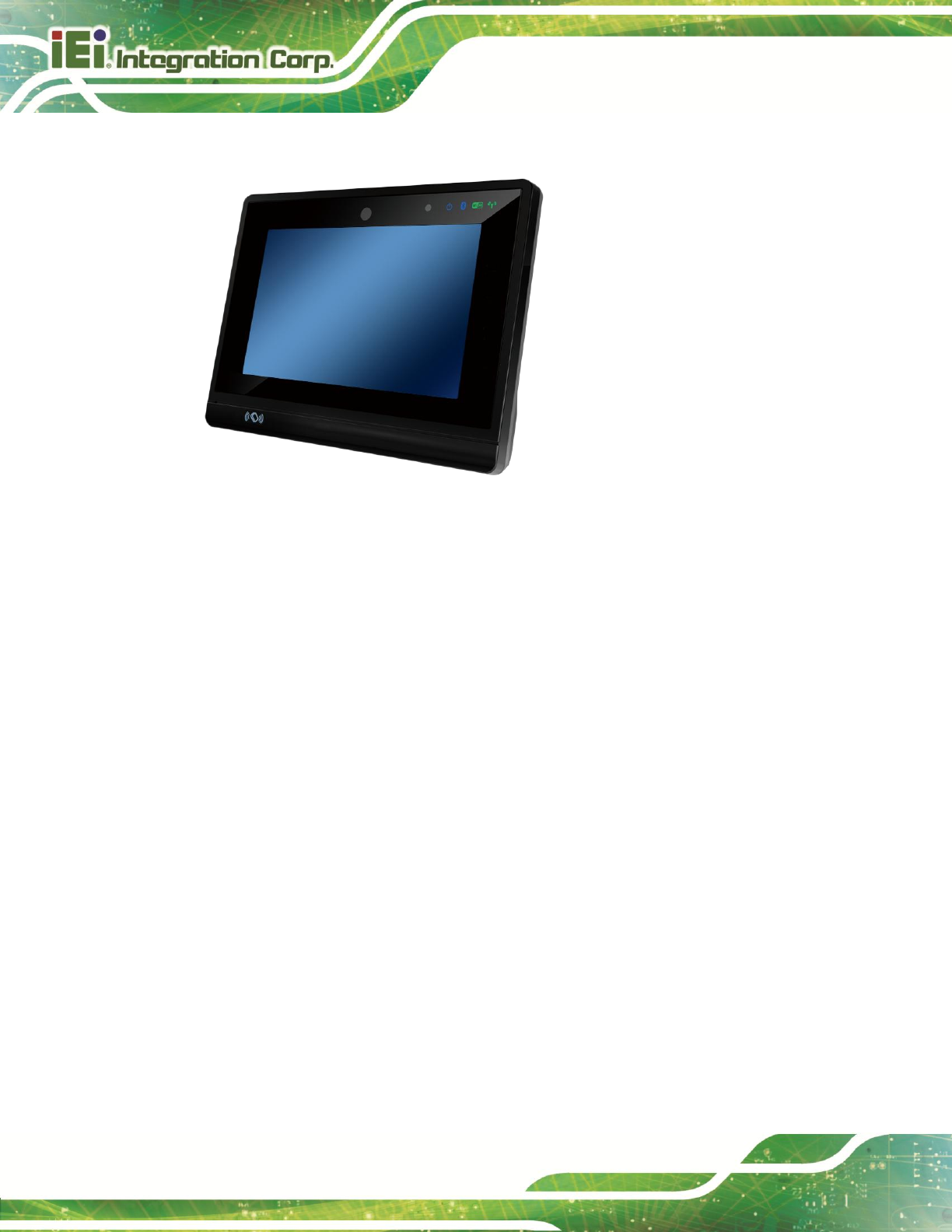
Figure 1-1: IKARPC-07A-A9 Panel PC
The IKARPC-07A-A9 is a 7” Android-based panel PC
At the heart of the system is the Freescale™ i.MX6 ARM Cortex™-A9 processor, offering
low power in a powerful package. The system also offers a multimedia experience with a
built-in camera, microphone and speaker. Other peripherals include one USB port, one
video input connector, and two I/O connectors which support RS-232, OBD-II, CAN 2.0 B,
digital I/O, USB and audio input/output. Wireless networking capabilities include
Bluetooth and 802.11a/b/g/n.
1.2 Features
The IKARPC-07A-A9 features the following:
2-point projected capacitive touchscreen
Freescale™ i.MX6 ARM Cortex™-A9 processor
On-board 1.0 GB SDRAM memory
Pre-installed Android 4.2 operating system
802.11a/b/g/n wireless
Bluetooth + EDR Class 1
3.75G connectivity with optional external antenna
Support OBD-II, CAN 2.0 B, digital I/O and RS-232
IKARPC-07A-A9 In-vehicle Panel PC
Page 3
GPS antenna connector
5-megapixel front-facing camera, speaker, microphone
IP 54 compliant front panel
RoHS compliance
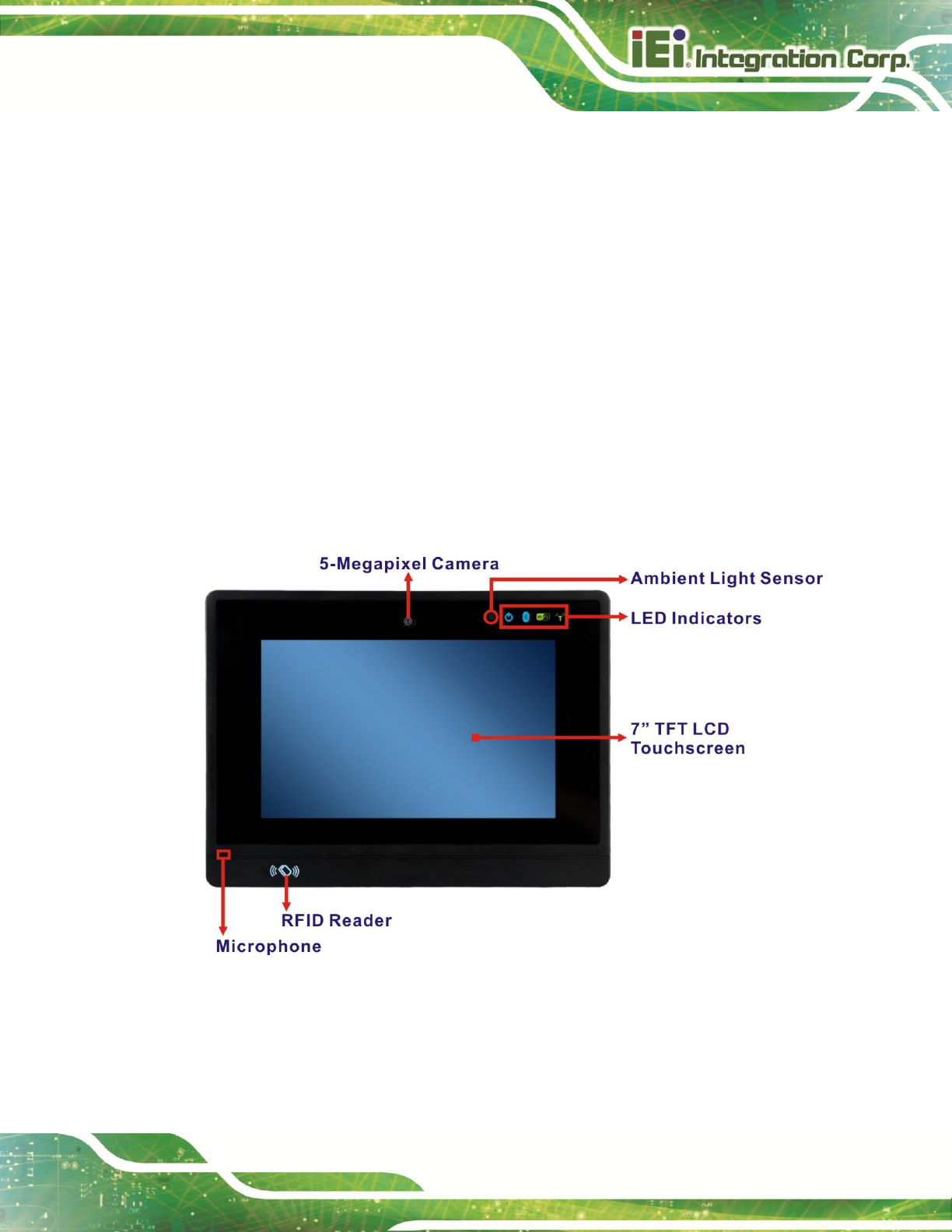
1.3 Front Panel
The front of the IKARPC-07A-A9 is a flat panel screen with a plastic frame. The
components on the front panel are listed below:
5-megapixel camera
Ambient light sensor
LED indicators (see Section 1.3.1)
Microphone
RFID reader
Figure 1-2: Front View
IKARPC-07A-A9 In-vehicle Panel PC
Page 4
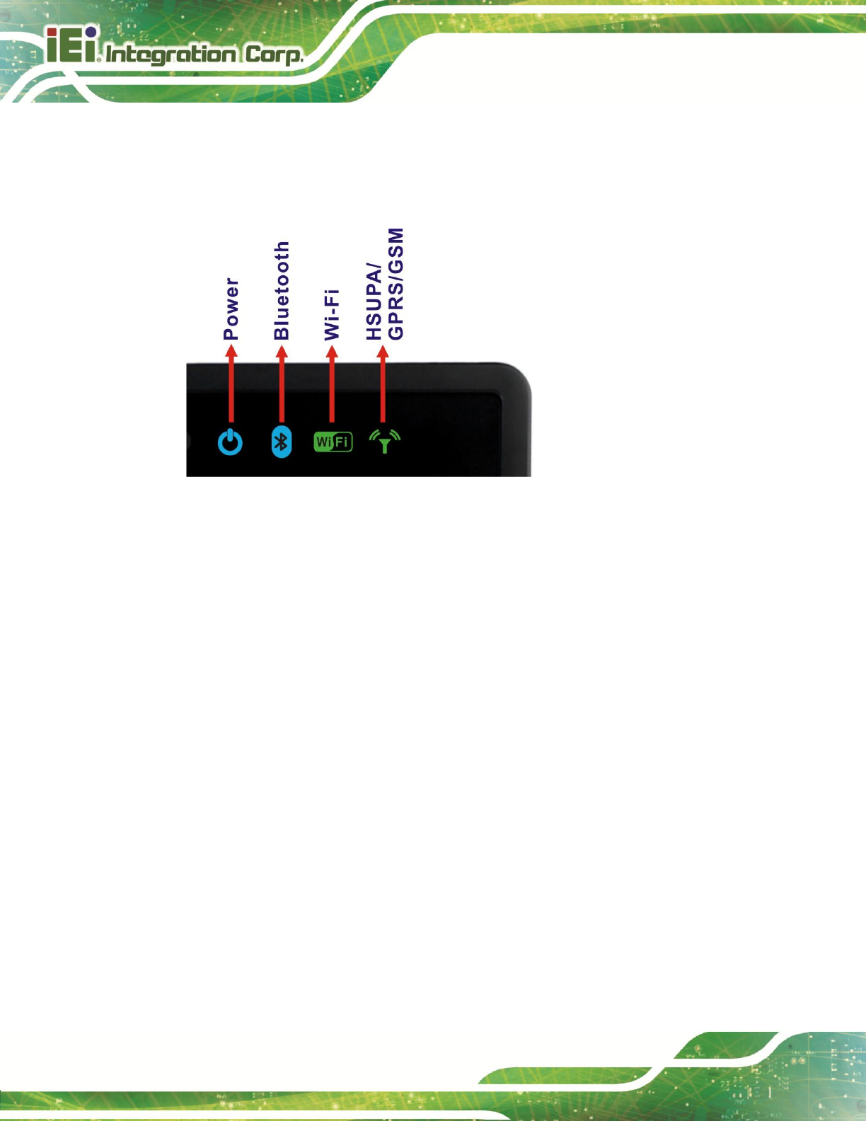
1.3.1 LED Indicators
The LED indicators on the front panel show the status of power, Bluetooth, Wi-Fi and
GPRS/HSUPA connection.
Figure 1-3: LED Indicators
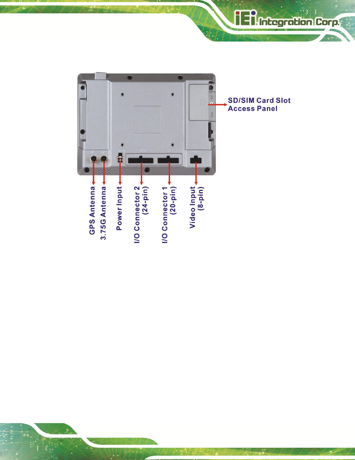
1.4 Rear Panel
The rear panel has VESA mounting screw holes and an access panel for SD card and SIM
card. The following I/O connectors can also be found on the rear panel.
1 x 12 V/24 V DC input connector
20-pin connector:
o 1 x 10/100 Mbps LAN
o 1 x CAN 2.0 B
o 1 x OBD-II
o 1 x USB
24-pin connector:
o 1 x Audio line-out (R+L)
o 1 x Audio line-in
o 1 x RS-232
o 2-bit digital input
o 2-bit digital output
8-pin connector:
o 4 x Video in
IKARPC-07A-A9 In-vehicle Panel PC
Page 5
1 x 3.75G antenna connector
1 x GPS antenna connector
Figure 1-4: Rear View
IKARPC-07A-A9 In-vehicle Panel PC
Page 6
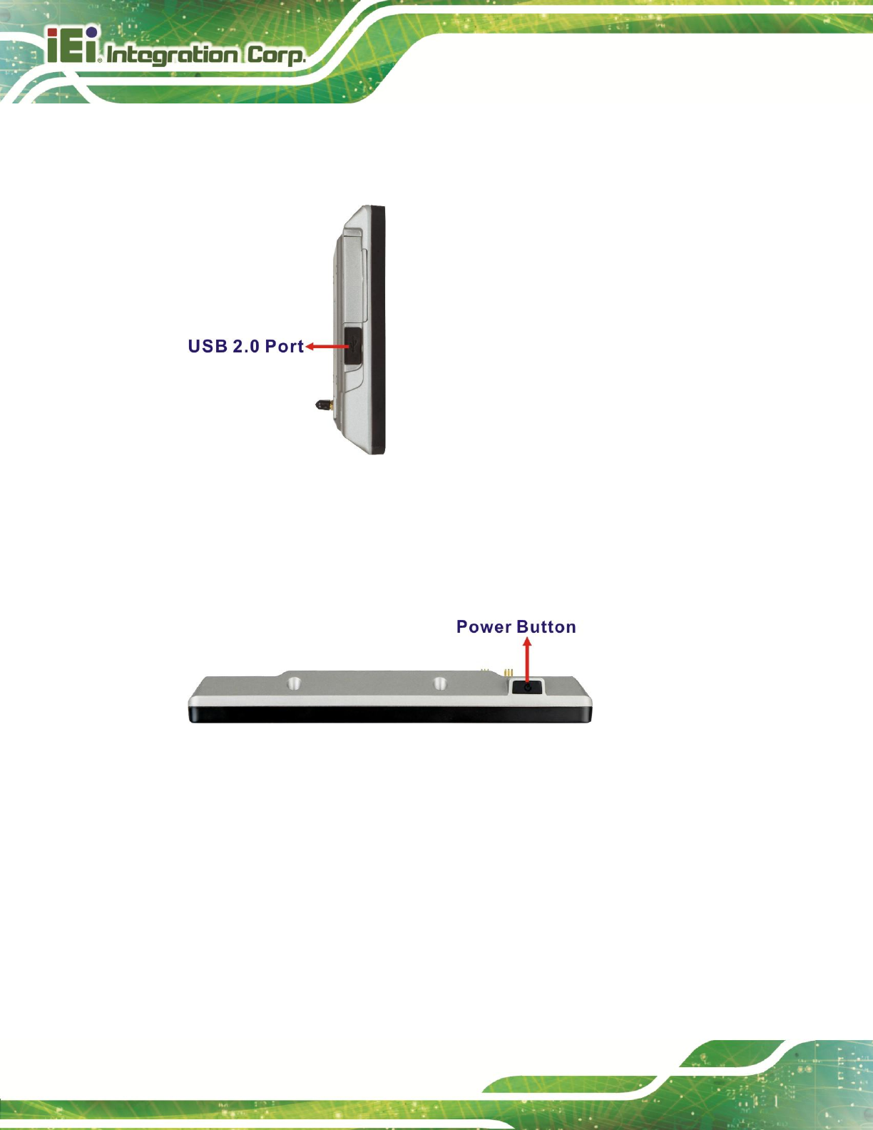
1.5 Right Side Panel
The right side panel has one USB 2.0 host port.
Figure 1-5: Right Side Panel
1.6 Top Panel
The top panel has a power button. Press the power button for 4~6 seconds to power on
the system.
Figure 1-6: Top Panel
IKARPC-07A-A9 In-vehicle Panel PC
Page 7
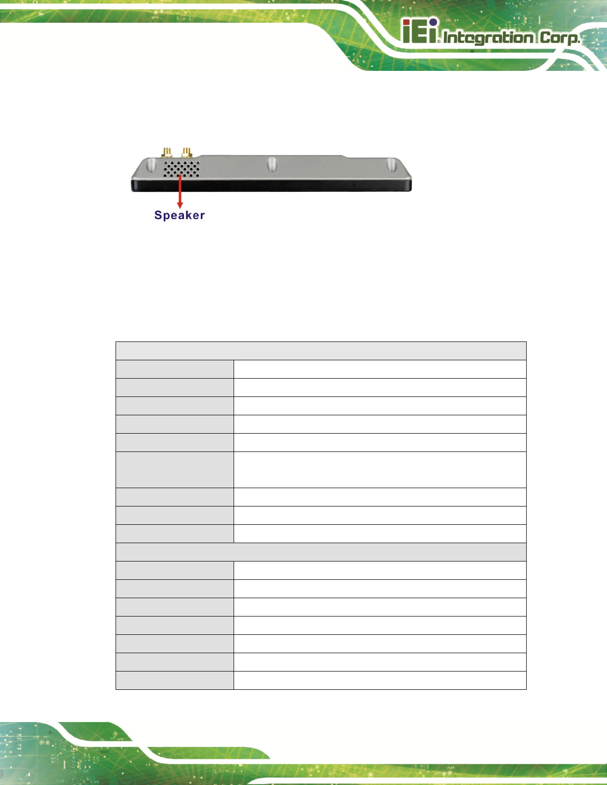
1.7 Bottom Panel
The bottom panel has a 2 W speaker.
Figure 1-7: Bottom Panel
1.8 System Specifications
The technical specifications for the IKARPC-07A-A9 systems are listed in Table 1-1.
System
CPU
Freescale™ i.MX6 ARM Cortex™-A9 processor
Memory
On-board 1 GB SDRAM memory
Boot Flash
On-board 8 GB iNAND flash
OS
Android 4.2
Storage
One SD card slot (SD 2.0 compatible, max. 32 GB)
Audio
1 x Speaker (2 W)
1 x Microphone
Camera
Front-facing 5-megapixel camera
Watchdog Timer
Software programmable supports 1~255 sec. system reset
Real-time Clock
Battery backup RTC
Display
LCD
7” TFT LCD with LED backlight
Max. Resolution
1024 x 600 (WSVGA)
Brightness (cd/m2)
500
Contrast Ratio
700:1
Viewing Angle
75/75/70/75 degree
Touchscreen
2-point projected capacitive touchscreen with USB interface
Auto-dimming
Ambient light sensor on the front panel
IKARPC-07A-A9 In-vehicle Panel PC
Page 8
Communication
LAN
1 x 10/100 Mbps
Wireless LAN
802.11a/b/g/n
Bluetooth
Bluetooth + HS
WWAN
Built-in u-blox LISA-U200-02S 3.75G UMTS/HSPA+ module supports:
HSPA/UMTS-800/850/1900/2100 MHz
Quad-band EDGE/GPRS/GSM-850/900/1800/1900MHz
GPS
Built-in u-blox NEO-M8N GPS module with external antenna
RFID
On-board RFID antenna
13.56MHz protocols supported:
ISO/IEC 14443A, ISO/IEC 14443B PCD 106 kbit/s to 848 kbit/s
ISO/IEC 14443A, ISO/IEC 14443B PICC 106 kbit/s to 424 kbit/s
Power
Power Input
4-pin (2x2) Molex power connector supports DC or ACC power
DC Power
12 V/24 V DC input via cigarette lighter power cable
ACC Power
ACC power on/off mode with software configurable delay time
Physical Character
Construction Material
ABS + PC plastic front frame
Mounting
VESA 75 mm x 75 mm
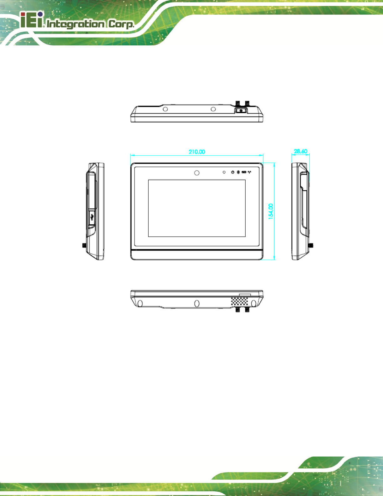
Dimensions (W x H x D)
210 mm x 154 mm x 29 mm
Operation Temperature
-20ºC ~ 60ºC with air flow
Storage Temperature
-30ºC ~ 70ºC
Humidity
5% ~ 85%, non-condensing
Net Weight
800 g
Operating Shock
Half-sine wave shock 5 G, 11 ms, 3 shocks per axis
Operating Vibration
MIL-STD-810G 514.6C-1 (with SSD)
IP level
IP 54 compliant front panel
Safety
CE, FCC, e-MARK
Connectors and Buttons
Antenna Connectors
1 x 3.75G antenna SMA female connector
1 x GPS antenna SMA female connector
Expansion Slot
1 x SIM card slot
I/O Ports
1 x 12 V/24 V DC input connector
1 x USB host port
IKARPC-07A-A9 In-vehicle Panel PC
Page 9
20-pin connector:
1 x 10/100 Mbps LAN
1 x CAN 2.0 B
1 x OBD-II
1 x USB
24-pin connector:
1 x Audio line-out (R+L)
1 x Audio line-in
1 x RS-232
2-bit digital input
2-bit digital output
8-pin connector:
4 x Video input
Button
1 x Power button
LED Indicators
1 x Power LED
1 x Bluetooth status LED
1 x Wi-Fi connection LED
1 x 3G connection LED
Table 1-1: Technical Specifications
IKARPC-07A-A9 In-vehicle Panel PC
Page 10
1.9 Dimensions
The dimensions are shown below.
Figure 1-8: Dimensions (unit: mm)

IKARPC-07A-A9 In-vehicle Panel PC
Page 11
Chapter
2
2 Unpacking

IKARPC-07A-A9 In-vehicle Panel PC
Page 12
To unpack the panel PC, follow the steps below:
WARNING!
The front side LCD screen has a protective plastic cover stuck to the
screen. Only remove the plastic cover after the system has been
properly installed. This ensures the screen is protected during the
installation process.
Step 1: Use box cutters, a knife or a sharp pair of scissors that seals the top side of the
external (second) box.
Step 2: Open the external (second) box.
Step 3: Use box cutters, a knife or a sharp pair of scissors that seals the top side of the
internal (first) box.
Step 4: Lift the monitor out of the boxes.
Step 5: Remove both polystyrene ends, one from each side.
Step 6: Pull the plastic cover off the flat panel PC.
Step 7: Make sure all the components listed in the packing list are present.
2.1 Packing List
NOTE:
If any of the components listed in the checklist below are missing, do
not proceed with the installation. Contact the IEI reseller or vendor the
IKARPC-07A-A9 was purchased from or contact an IEI sales
representative directly by sending an email to 326H378Hsales@ieiworld.com.
IKARPC-07A-A9 In-vehicle Panel PC
Page 13
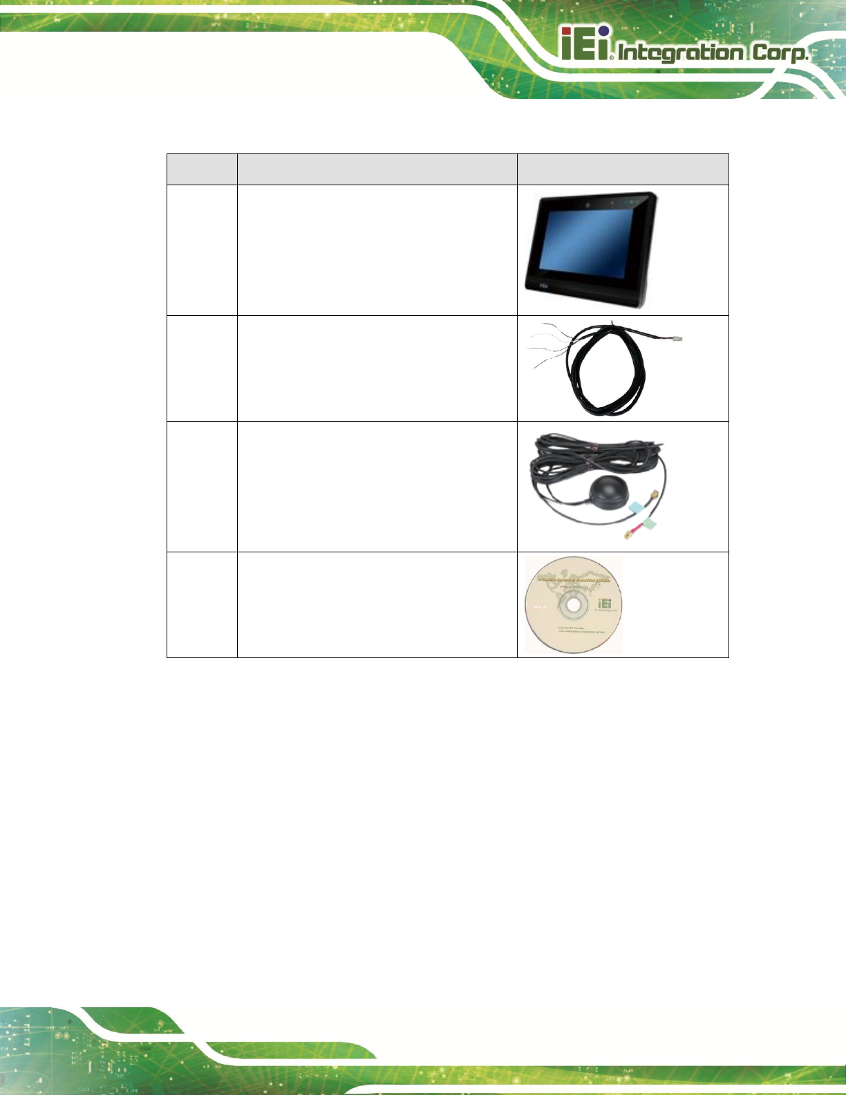
The IKARPC-07A-A9 is shipped with the following components:
Quantity
Item
Image
1
IKARPC-07A-A9 panel PC
1
ACC power cable
(P/N: 32002-001900-100-RS)
1
GPS/GSM antenna
(P/N: 32506-000100-100-RS)
1
User manual CD and driver CD
Table 2-1: Packing List
If any of these items are missing or damaged, contact the distributor or sales
representative immediately.

IKARPC-07A-A9 In-vehicle Panel PC
Page 14
Chapter
3
3 Installation

IKARPC-07A-A9 In-vehicle Panel PC
Page 15
3.1 Anti-static Precautions
WARNING:
Failure to take ESD precautions during the maintenance of the
IKARPC-07A-A9 may result in permanent damage to the
IKARPC-07A-A9 and severe injury to the user.
Electrostatic discharge (ESD) can cause serious damage to electronic components,
including the IKARPC-07A-A9. Dry climates are especially susceptible to ESD. It is
therefore critical that whenever the IKARPC-07A-A9 is accessed internally, or any other
electrical component is handled, the following anti-static precautions are strictly adhered
to.
Wear an anti-static wristband: Wearing a simple anti-static wristband can
help to prevent ESD from damaging the board.
Self-grounding: Before handling the board, touch any grounded conducting
material. During the time the board is handled, frequently touch any
conducting materials that are connected to the ground.
Use an anti-static pad: When configuring the IKARPC-07A-A9, place it on an
anti-static pad. This reduces the possibility of ESD damaging the
IKARPC-07A-A9.
Only handle the edges of the PCB: When handling the PCB, hold the PCB
by the edges.
3.2 Installation Precautions
When installing the flat panel PC, please follow the precautions listed below:
Power turned off: When installing the flat panel PC, make sure the power is
off. Failing to turn off the power may cause severe injury to the body and/or
damage to the system.
Certified Engineers: Only certified engineers should install and modify
onboard functionalities.
IKARPC-07A-A9 In-vehicle Panel PC
Page 16
Anti-static Discharge: If a user open the rear panel of the flat panel PC, to
configure the jumpers or plug in added peripheral devices, ground themselves
first and wear an anti-static wristband.
3.3 Installation and Configuration Steps
The following installation steps must be followed.
Step 1: Unpack the system
Step 2: Install a SD card
Step 3: Install a SIM card
Step 4: Mount the system
Step 5: Connect peripheral devices
Step 6: Power up the system Step 0:
3.4 SD Card Installation
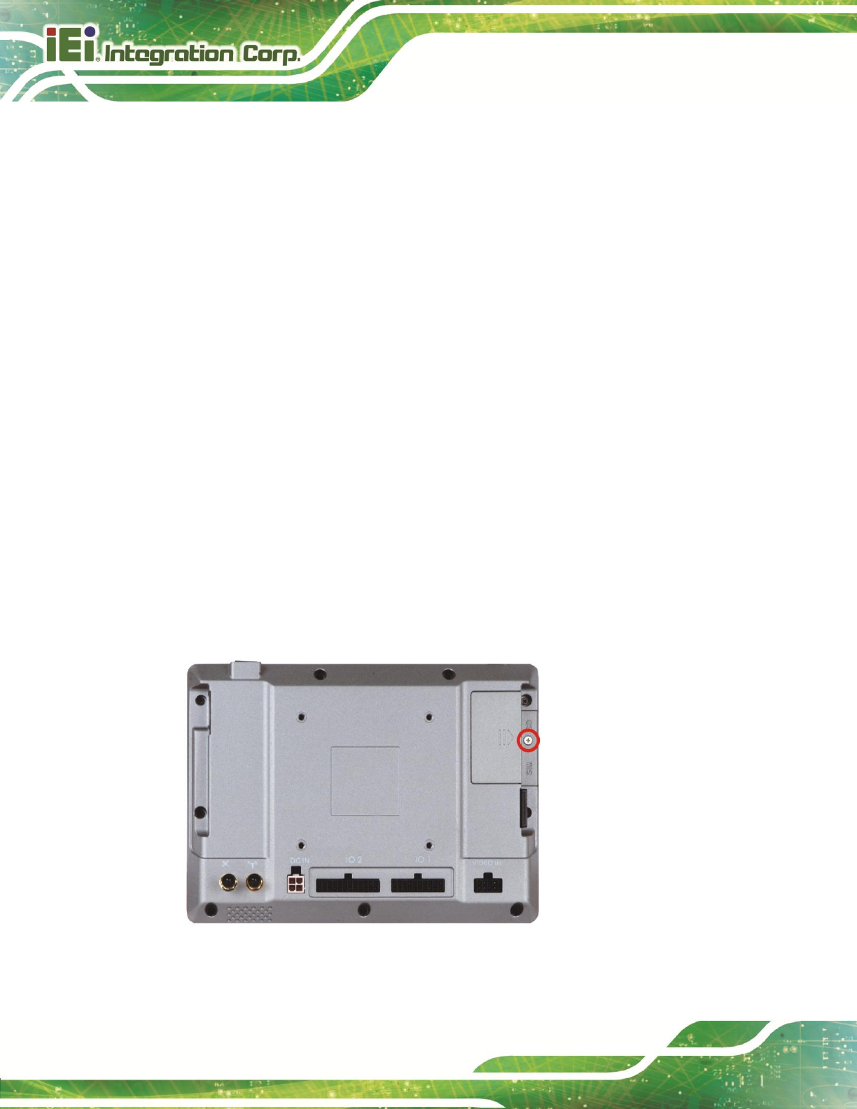
To install the SD card, follow the instructions below.
Step 1: Remove the retention screw and lift the SD card slot access panel.
Figure 3-1: SD Card Slot Access Panel Retention Screw
IKARPC-07A-A9 In-vehicle Panel PC
Page 17
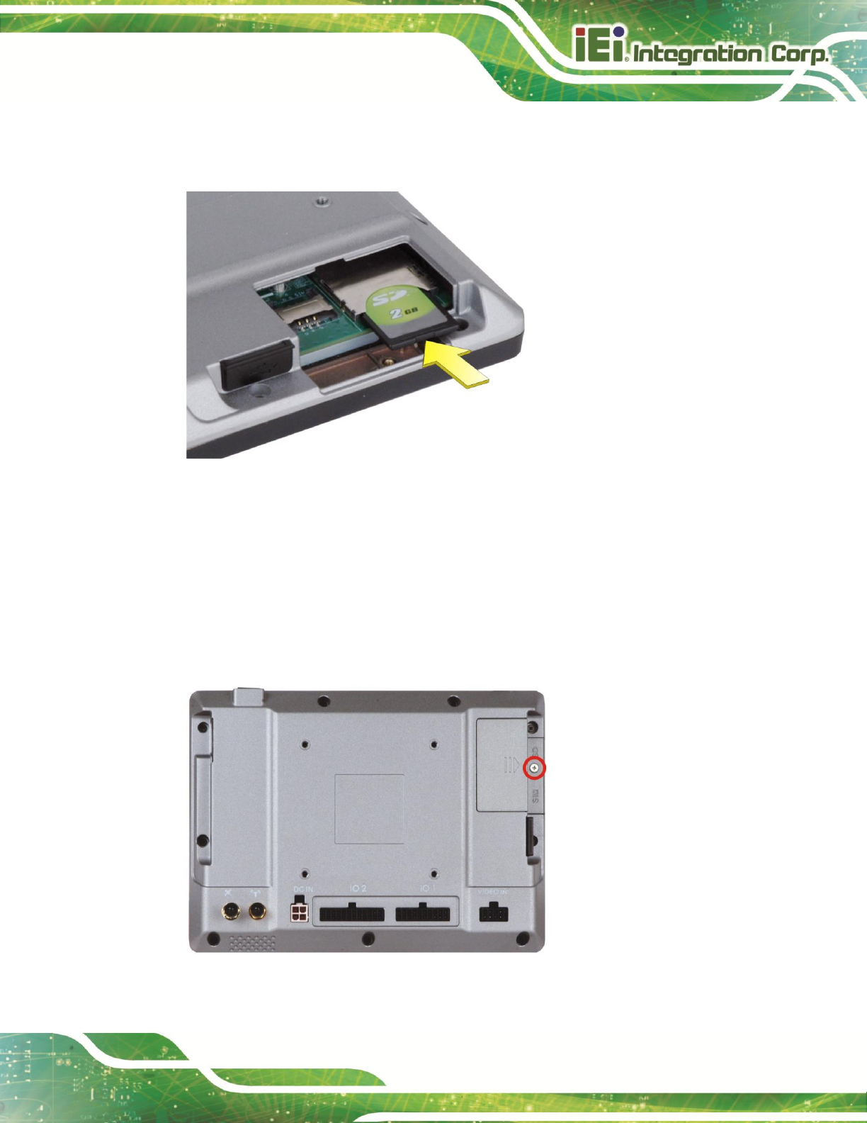
Step 2: Locate the SD card slot. Insert the SD card into the slot to install it. To remove
the SD card, push the SD card inward to release it.
Figure 3-2: Install SD Card
Step 3: Replace the SD card slot access panel. Step 0:
3.5 SIM Card Installation
To install the SIM card, follow the instructions below.
Step 1: Remove the retention screw and lift the SIM card slot access panel.
Figure 3-3: SIM Card Slot Access Panel Retention Screw
IKARPC-07A-A9 In-vehicle Panel PC
Page 18
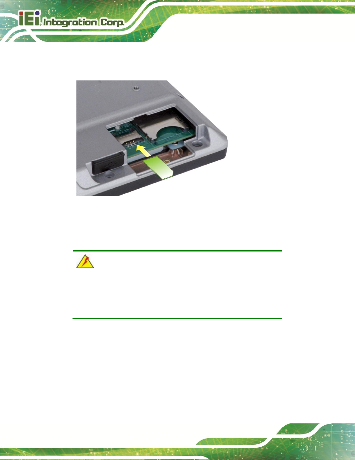
Step 2: Locate the SIM card slot. Insert the SIM card into the slot to install it. To remove
the SIM card, slide the SIM card outward.
Figure 3-4: Install SIM Card
Step 3: Replace the SIM card slot access panel. Step 0:
WARNING:
The IKARPC-07A-A9 is not compatible with a micro-SIM (3FF) adapter
or a nano-SIM (4FF) adapter. Please install a mini-SIM (2FF or
Standard SIM) card for proper network connection.
IKARPC-07A-A9 In-vehicle Panel PC
Page 19
3.6 Mounting the System
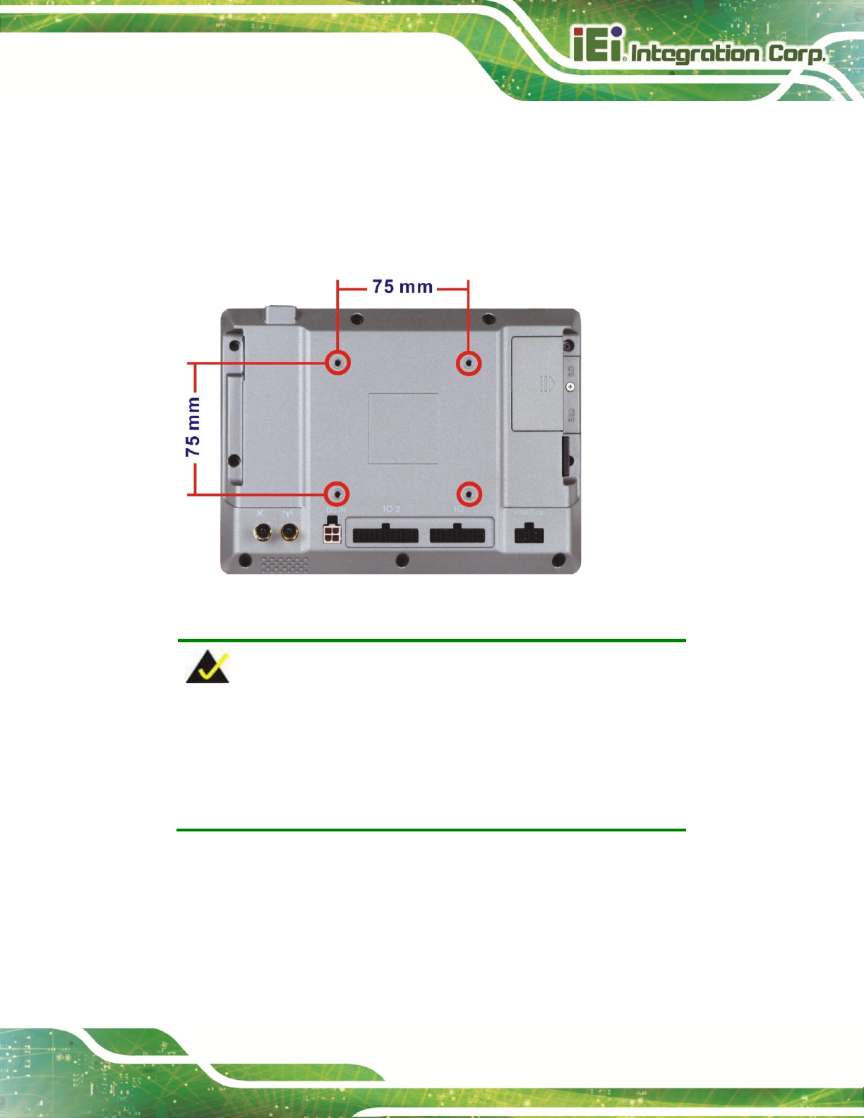
The IKARPC-07A-A9 is VESA (Video Electronics Standards Association) compliant and
can be mounted on a mounting device with a 75 mm interface pad. The IKARPC-07A-A9
VESA mount retention screw holes are shown in Figure 3-5. Refer to the installation
documentation that came with the mounting device to mount the IKARPC-07A-A9.
Figure 3-5: VESA Mount Retention Screw Holes
NOTE:
When purchasing the mounting device please ensure that it is VESA
compliant and that the device has a 75 mm interface pad. If the
mounting device is not VESA compliant it cannot be used to support
the IKARPC-07A-A9.
IKARPC-07A-A9 In-vehicle Panel PC
Page 20
3.7 External I/O Connectors
This section provides an overview of the external I/O connectors of the IKARPC-07A-A9.
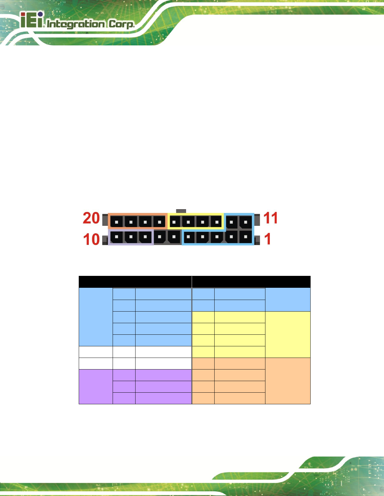
3.7.1 I/O Connector 1 (20-pin)
The 20-pin I/O connector (IO 1) supports the following external peripheral devices:
1 x 10/100 Mbps LAN
1 x CAN 2.0 B
1 x OBD-II
1 x USB
The pinouts for the IO 1 connector are listed in the figure and table below.
Figure 3-6: IO 1 Connector Pinout Locations
Pin
Description
Pin
Description
1
OBD_CAN_H
11
ISO9141-2-K
OBD-II
2
OBD_CAN_L
12
ISO9141-2-L
OBD-II
3
GND
13
LAN_MDI0-
10/100 Mbps
4
J2850_BUS+
14
LAN_MDI0+
LAN
5
J2850_BUS-
15
LAN_MDI1-
6
GND
16
LAN_MDI1+
7
GND
17
GND
USB 2.0
CAN Bus
8
GND
18
USB DATA-
9
CAN_L
19
USB DATA+
10
CAN_H
20
USB VCC (+5V)
Table 3-1: IO 1 Connector Pinouts
IKARPC-07A-A9 In-vehicle Panel PC
Page 21
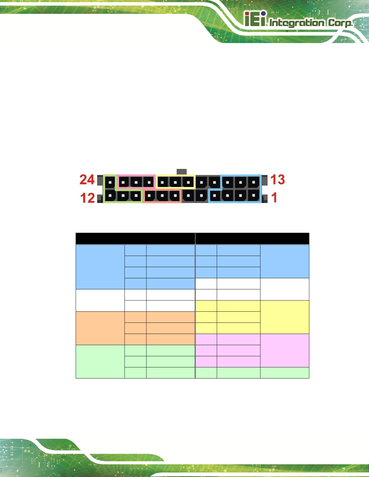
3.7.2 I/O Connector 2 (24-pin)
The 24-pin I/O connector (IO 2) supports the following external peripheral devices:
1 x Audio line-out (R+L)
1 x Audio line-in
1 x RS-232
2-bit digital input
2-bit digital output
The pinouts for the IO 2 connector are listed in the figure and table below.
Figure 3-7: IO 2 Connector Pinout Locations
Pin
Description
Pin
Description
COM
1
COM_TXD
13
COM_RXD
COM
2
NC
14
NC
3
COM_RTS
15
COM_CTS
4
COM_GND
16
NC
5
NC
17
NC
6
NC
18
DIO_GND
Digital Input
Digital Output
7
DIO_OUT_1
19
DIO_IN_1
8
DIO_OUT_2
20
DIO_IN_2
9
DIO_GND
21
AUDIO_GND
Audio Line-in
Audio Line-out
10
AUDIO_GND
22
LINE_IN_L
11
HP_OUT_L
23
LINE_IN_R
12
HP_OUT_R
24
HP_DET_IN
Table 3-2: IO 2 Connector Pinouts
IKARPC-07A-A9 In-vehicle Panel PC
Page 22
NOTE:
In order to play sounds through the headset connected to the audio
line-out connector, the “Switch to HeadPhone” option must be enabled.
Please refer to Section 4.4.2 for detail information.
3.7.3 Video Input Connector
The IKARPC-07A-A9 has one 8-pin video input connector on the rear panel. The pinouts
for the video input connector are listed in the figure and table below.
Figure 3-8: Video Input Connector
PIN NO.
DESCRIPTION
1
VIDEO_GND_3
2
VIDEO_GND_2
3
VIDEO_GND_1
4
VIDEO_GND_0
5
VIDEO_AIN_3
6
VIDEO_AIN_2
7
VIDEO_AIN_1
8
VIDEO_AIN_0
Table 3-3: Video Input Connector Pinouts
IKARPC-07A-A9 In-vehicle Panel PC
Page 23
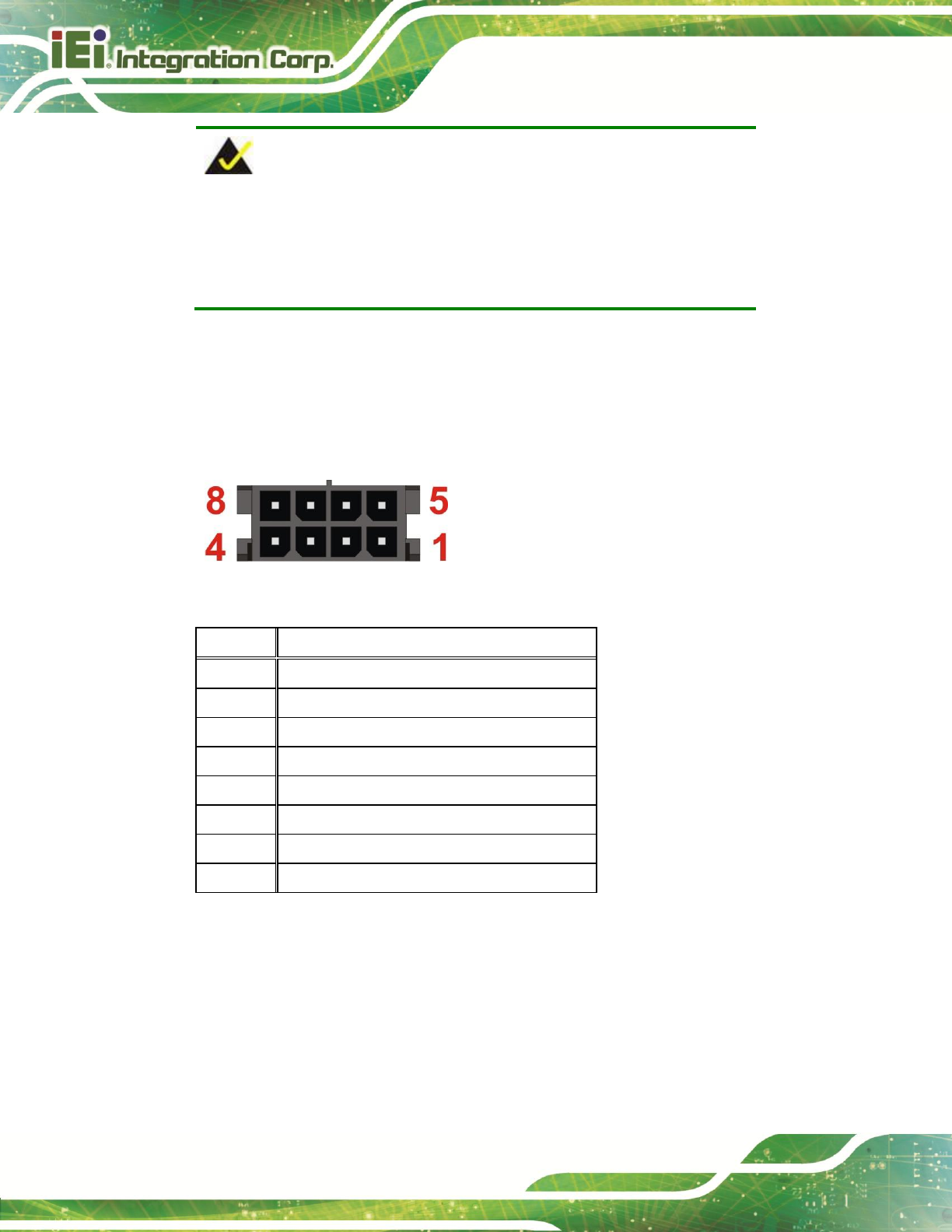
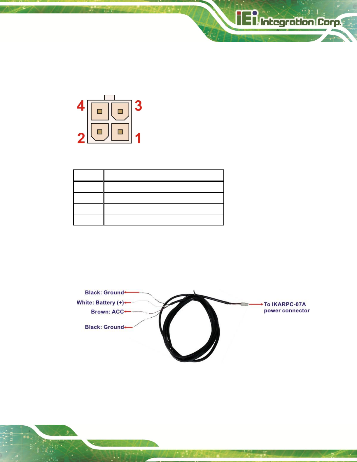
3.7.4 Power Input Connection
The IKARPC-07A-A9 has one 4-pin power input connector on the rear panel. The pinouts
for the power input connector are listed in the figure and table below.
Figure 3-9: Power Input Connector
PIN NO.
DESCRIPTION
1
GND
2
GND
3
POWER
4
ACC
Table 3-4: Power Input Connector Pinouts
The IKARPC-07A-A9 can use either ACC power or DC power from the power source. To
use ACC power, connect the IKARPC-07A-A9 to the power source through the ACC
power cable. See Figure 3-10.
Figure 3-10: ACC Power Cable
IKARPC-07A-A9 In-vehicle Panel PC
Page 24
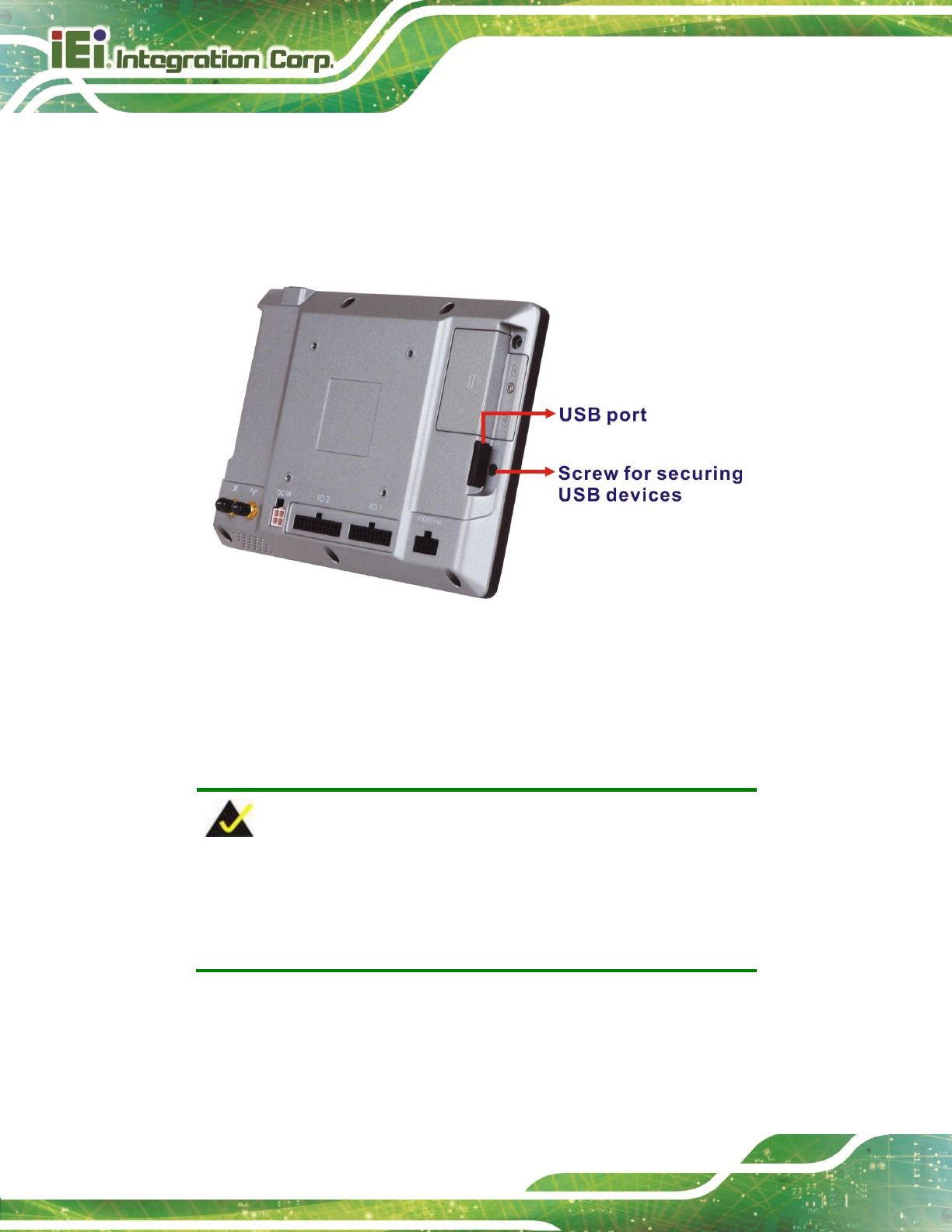
3.7.5 USB Connector
The IKARPC-07A-A9 has one USB 2.0 port on the right side panel. The USB port has a
screw on the side for securing the USB devices, such as barcode scanners and smart
card readers. The following diagram shows the USB port and the screw on the side panel.
Figure 3-11: USB Connector
3.8 System Maintenance
If the components of the IKARPC-07A-A9 fail, they must be replaced. Please contact the
system reseller or vendor to purchase the replacement parts.
NOTE:
A user cannot replace a motherboard. If the motherboard fails it must
be shipped back to IEI to be replaced. Please contact the system
vendor, reseller or an IEI sales person directly.

IKARPC-07A-A9 In-vehicle Panel PC
Page 25
Chapter
4
4 Using the
IKARPC-07A-A9

IKARPC-07A-A9 In-vehicle Panel PC
Page 26
4.1 Power-On/Off Procedure
4.1.1 Installation Checklist
WARNING:
Make sure a power supply with the correct input voltage is being fed into
the system. Incorrect voltages applied to the system may cause damage to
the internal electronic components and may also cause injury to the user.
To power on the system please make sure of the following:
The rear cover is installed
All peripheral devices (antenna, serial communications devices etc.) are
connected
The system is securely mounted
The power cables are plugged in
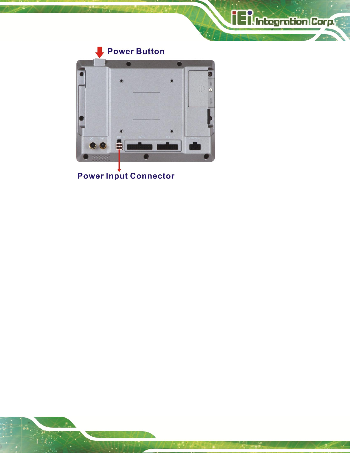
4.1.2 Power-on Procedure
To power-on the IKARPC-07A-A9 please follow the steps below:
Step 1: Connect the ACC power cable from the IKARPC-07A-A9 to the power source.
See Section 3.7.4.
IKARPC-07A-A9 In-vehicle Panel PC
Page 27
Figure 4-1: Power Connector and Power Button
Step 2: The system starts booting. When the main screen shows, press and slide the
lock button on the screen to the unlock icon to unlock the system.
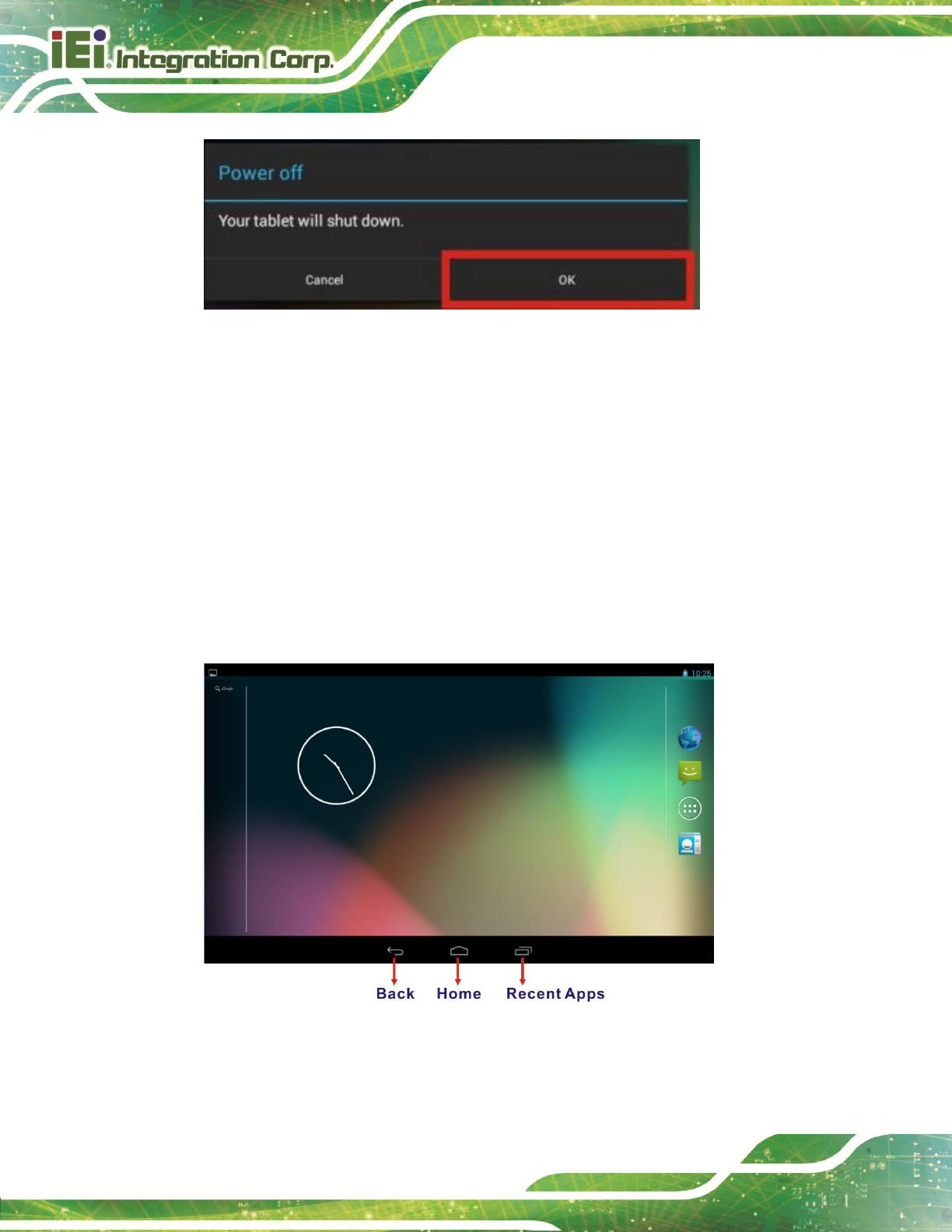
4.1.3 Power-off Procedure
To power-off the IKARPC-07A-A9 please follow the steps below:
Step 1: (1) Turn off the power source, or
(2) Hold down the power button for 4~6 seconds to turn off the system.
Step 2: The power-off confirmation window appears. Tap OK to turn off the system.
IKARPC-07A-A9 In-vehicle Panel PC
Page 28
Figure 4-2: Power-off Confirmation Screen
4.2 Home Screen
The IKARPC-07A-A9 has multiple home screens allowing users to customize the screen
with widgets, apps, folders and shortcuts. The following sections describe the basic
technique to manage the home screen.
4.2.1 Navigation Buttons
The IKARPC-07A-A9 Android home screen has three navigation buttons to control the
system. The navigation buttons are shown in Figure 4-3 and described in Table 4-1.
Figure 4-3: Navigation Buttons
IKARPC-07A-A9 In-vehicle Panel PC
Page 29
Buttons
Description
Back
Tap to return to the previous screen.
Home
Tap to return to the home screen.
Recent Apps
Tap to display all the recently used applications.
Table 4-1: Navigation Buttons
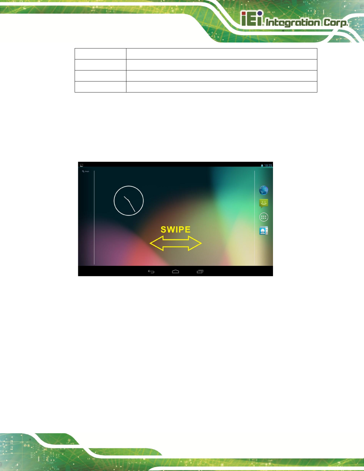
4.2.2 Multiple Home Screens
Swipe left or right to switch. Long press an item on the home screen and when it vibrates
drag the item to other screen.
Figure 4-4: Multiple Home Screens
4.2.3 Adding Shortcut
To add app or widget shortcuts on the home screen, follow the steps below.
Step 1: Click the launcher button on the home screen to access the launcher/widget
page.
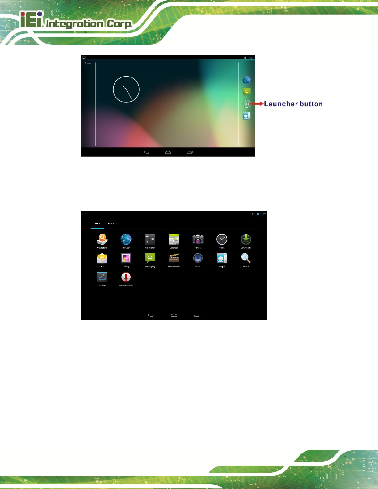
IKARPC-07A-A9 In-vehicle Panel PC
Page 30
Figure 4-5: Launcher Button
Step 2: Long press an app icon or a widget (click the WIDGETS tab to access the
widgets page). When it vibrates, drag app/widget to the home screen.
Figure 4-6: Launcher Page
IKARPC-07A-A9 In-vehicle Panel PC
Page 31
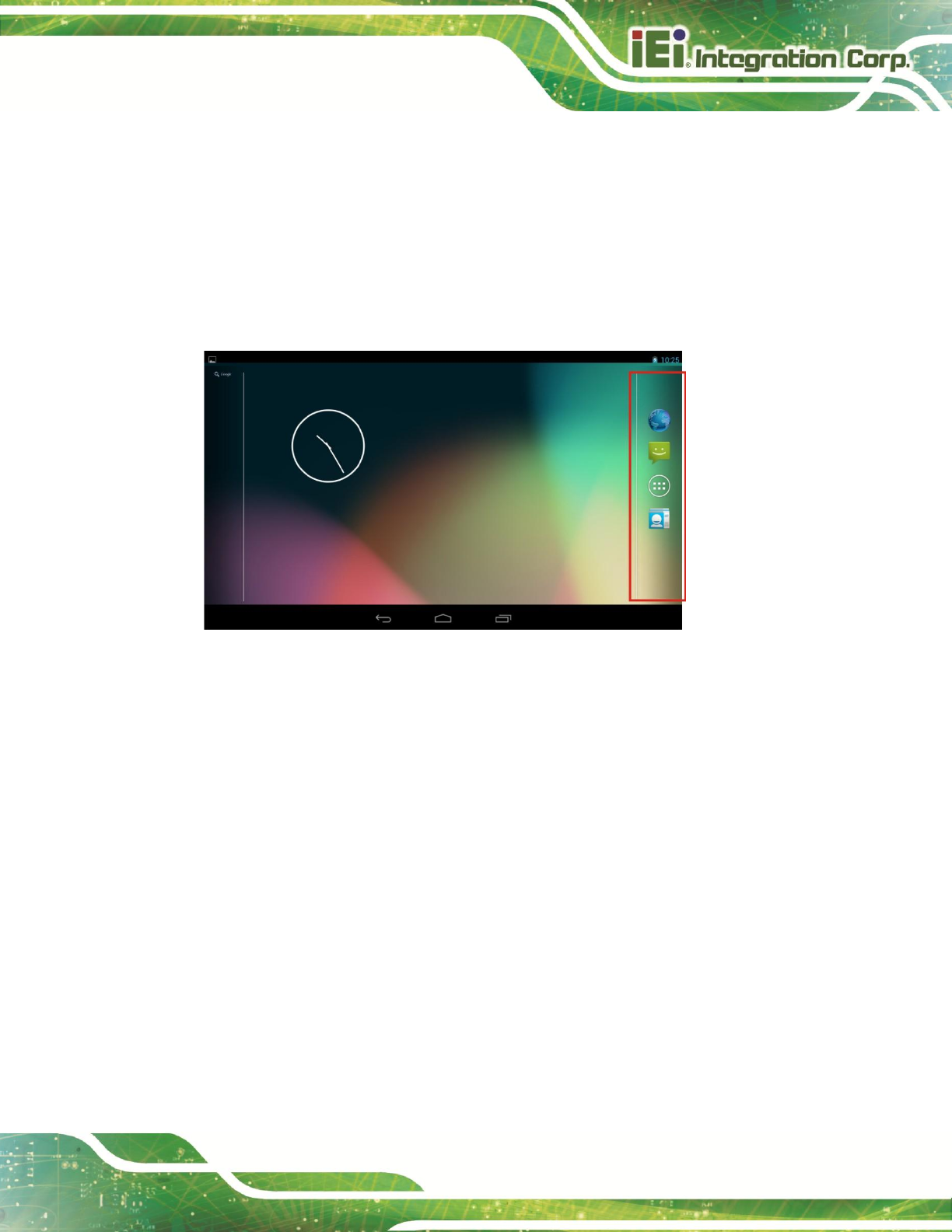
4.2.4 Favorites Tray
The Favorites tray at the side of each home screen allows users to keep the most
important or frequently used shortcuts and folders.
Long press an item on the home screen. When it vibrates, drag it to the favorites tray or
move it from the favorites tray. The launcher button at the center of the favorites tray is
fixed and can not be moved.
Figure 4-7: Favorites Tray
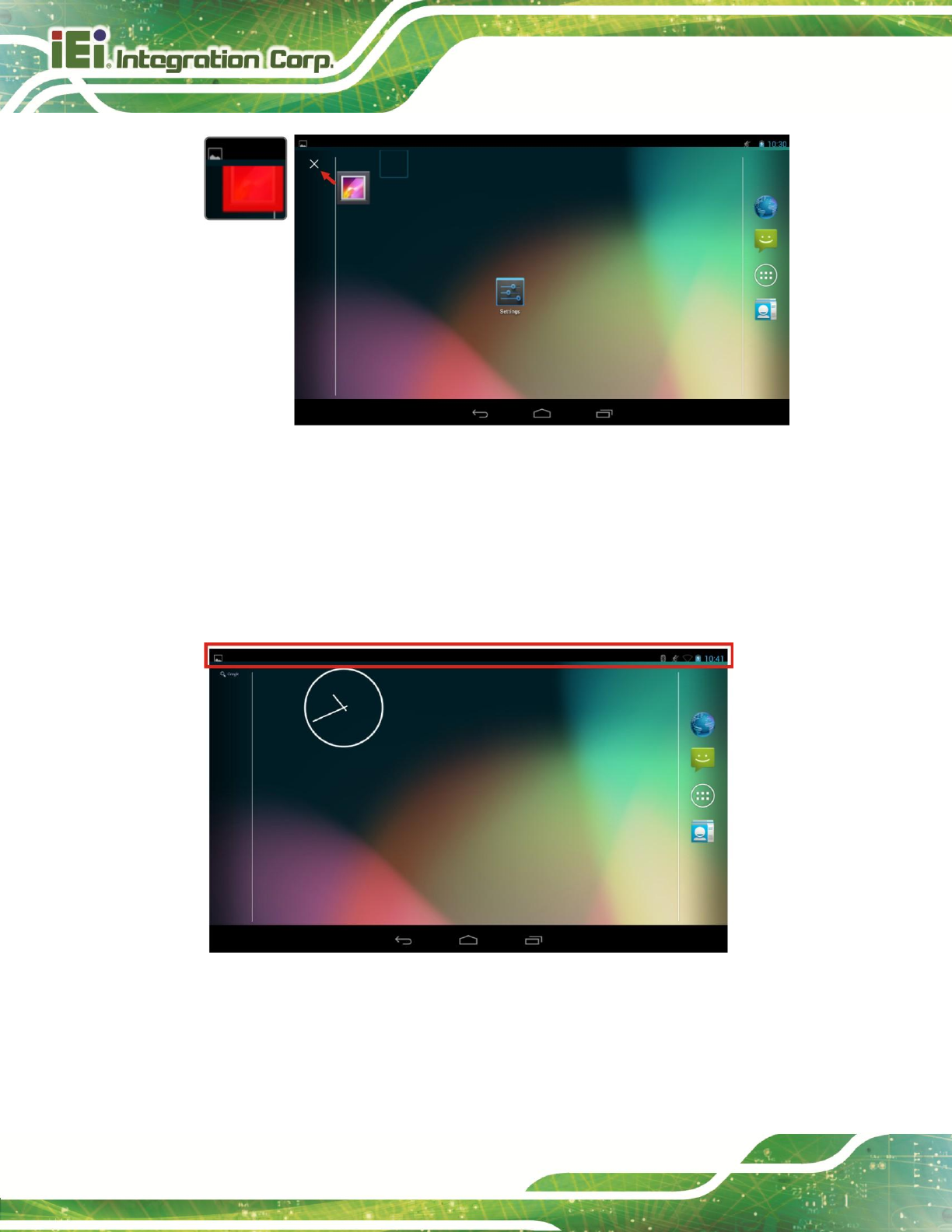
4.2.5 Arranging Home Screen
The items on the home screen can be moved and deleted. Long press an item on the
home screen. When it vibrates, drag it where you want. To trash the item on the desktop,
drag it to the “X” icon. Release the icon when it turns red.
IKARPC-07A-A9 In-vehicle Panel PC
Page 33
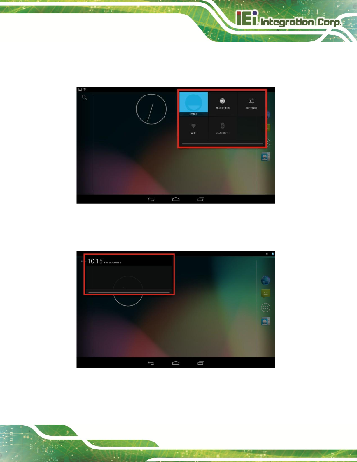
Swipe down from the right of the status bar to view the setting shortcut.
Figure 4-10: Status Bar – Setting Shortcut
Swipe down from the left of the status bar to view notification details.
Figure 4-11: Status Bar – Notification
IKARPC-07A-A9 In-vehicle Panel PC
Page 34
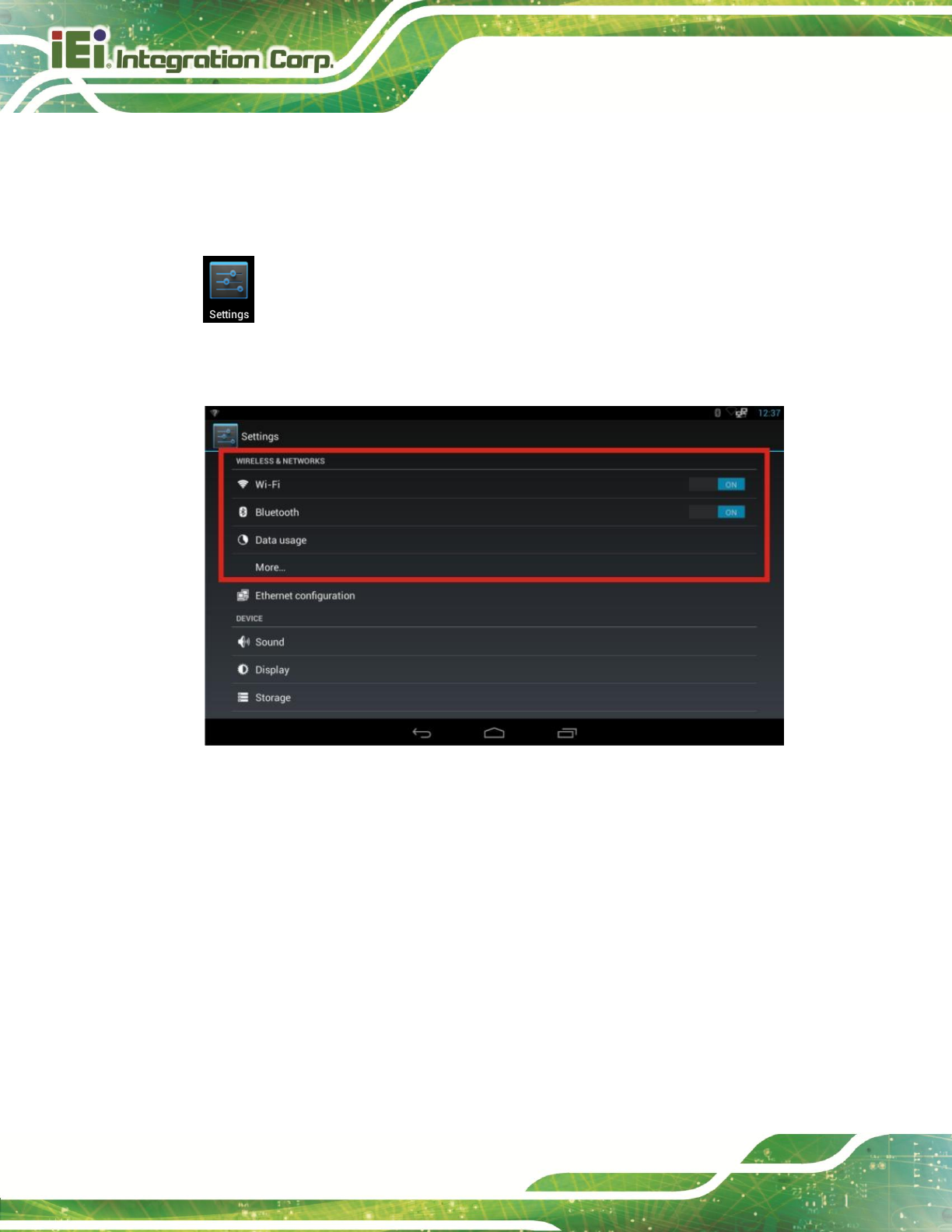
4.4 Settings
The Settings menu allows configuration to the IKARPC-07A-A9, such as Wi-Fi, volume,
screen brightness, etc. To enter the Settings menu, tap Settings on the launcher page.
4.4.1 WIRELESS & NETWORKS
Figure 4-12: Wireless and Networks Settings
In the WIRELESS & NETWORKS field, the user can turn on/off the Wi-Fi and Bluetooth
functions, and configure the network settings.
Wi-Fi
allows the user to turn on or turn off the Wi-Fi function. When the Wi-Fi
function is turned on, tap this item to manage the access points.
Bluetooth
allows the user to turn on or turn off the Bluetooth function. When the
Bluetooth function is turned on, tap this item to manage the Bluetooth
connections.
IKARPC-07A-A9 In-vehicle Panel PC
Page 35
Data usage
displays the data usage in a certain period of time.
Ethernet configuration
configures the Ethernet settings.
4.4.1.1 More Settings
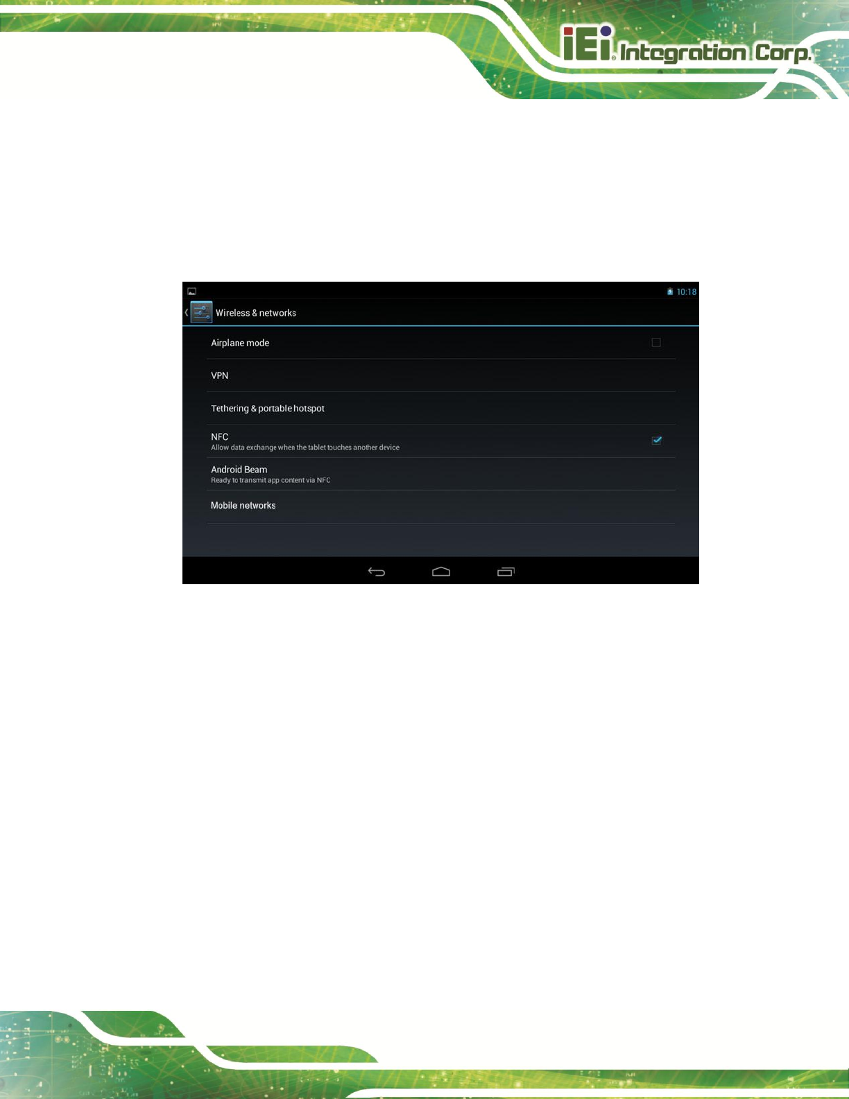
Figure 4-13: More Settings Menu
After tapping More… in the WIRELESS & NETWORKS field, the user can configure the
following network settings.
Airplane mode
turns on or turns off the airplane mode.
VPN
sets up and manages Virtual Private Networks (VPNs).
Tethering & portable hotspot
allows the user to set this device as a portable Wi-Fi hotspot and configure the
hotspot settings.
NFC
turns on or turns off the NFC function.
IKARPC-07A-A9 In-vehicle Panel PC
Page 36
Android Beam
allows the user to beam app content to another NFC-capable device when it
is enabled. This item is available only when the NFC function is turned on.
Mobile networks
configure Mobile network settings, including data enabled, data roaming,
access point names, use only 2G networks, and network operators.
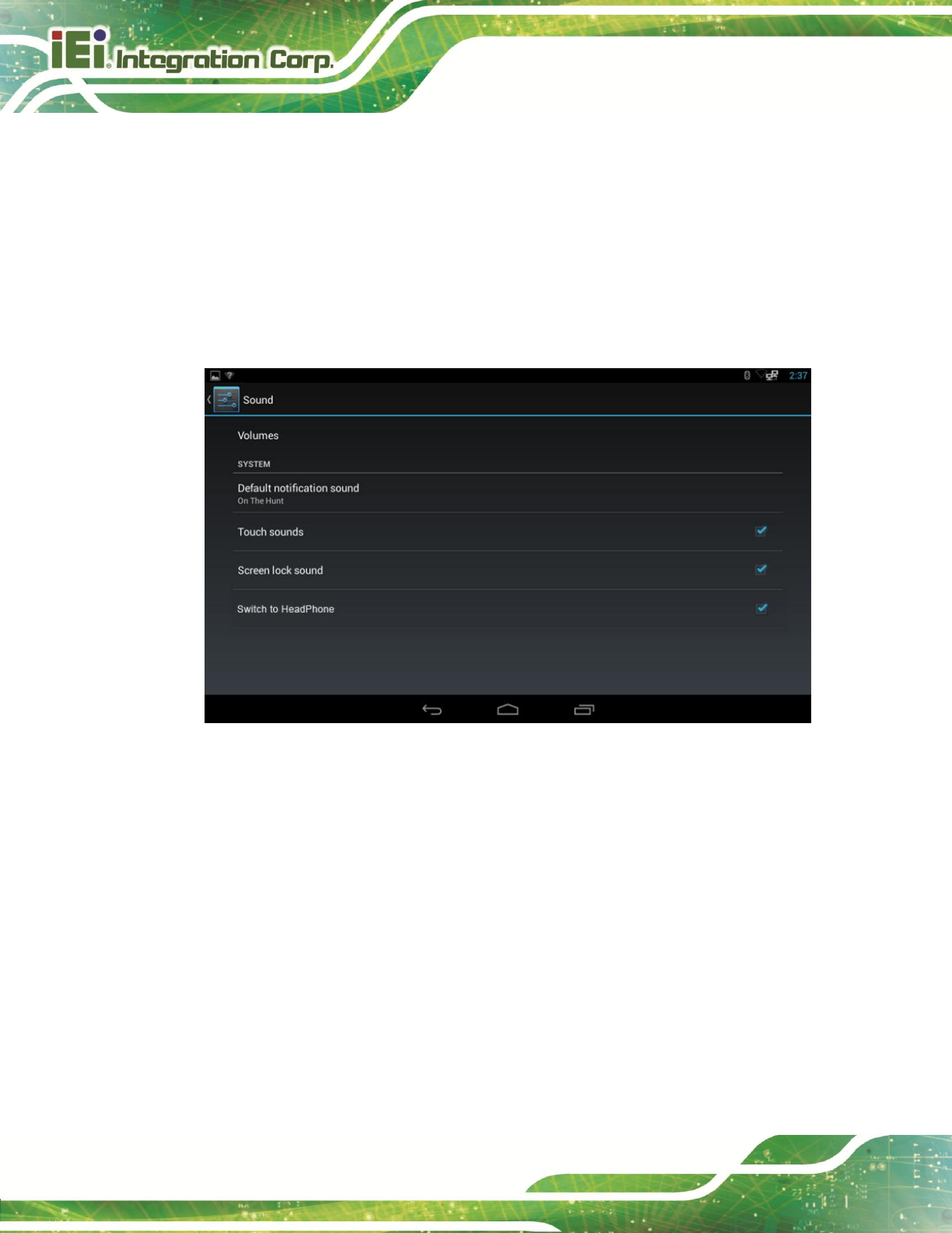
4.4.2 Sound
Figure 4-14: Sound Menu
Use the Sound menu to configure the following items.
Volumes
allowing the user to adjust the volume of alarms, notifications, music, video,
games and other media.
Default notification sound
sets up the notification ringtone.
Touch sounds
enables or disables playing a sound when making screen selection.
Screen lock sound
enables or disables playing a sound when unlocking the home screen.
IKARPC-07A-A9 In-vehicle Panel PC
Page 37
Switch to HeadPhone
allowing the user to play sounds through the headset connected to the audio
line-out connector of the IKARPC-07A-A9.
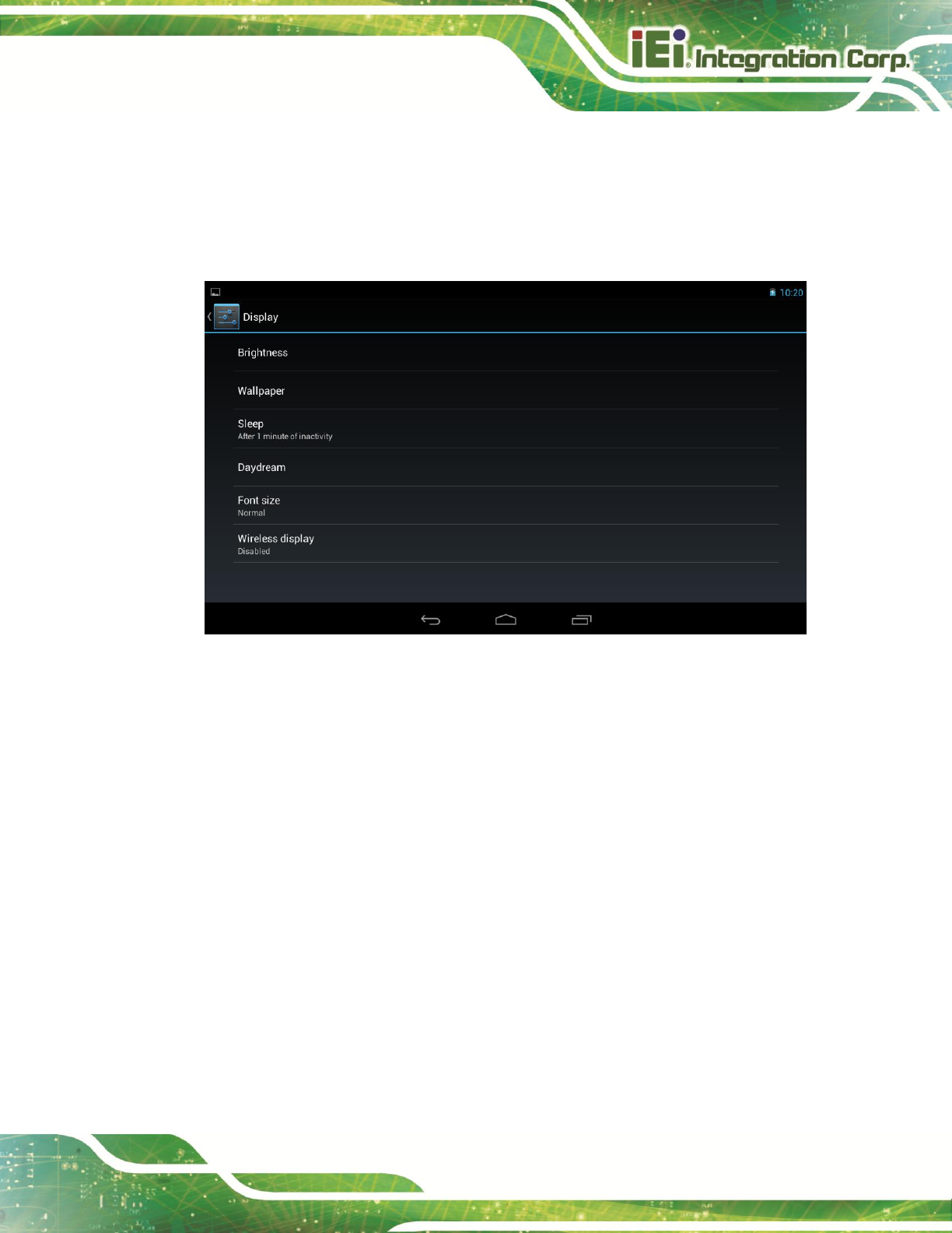
4.4.3 Display
Figure 4-15: Display Menu
Use the Display menu to configure the following items.
Brightness
adjusts the screen brightness.
Wallpaper
sets up the wallpaper.
Sleep
sets up the time of inactivity after which the screen turns to sleep mode.
Daydream
configures the screensaver settings.
Font size
sets up the font size.
Wireless display
turns on or turns off the wireless display function and configures its settings.
IKARPC-07A-A9 In-vehicle Panel PC
Page 38
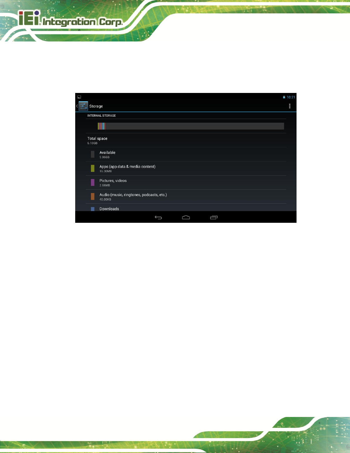
4.4.4 Storage
The Storage menu displays the status of the internal storage and the installed SD card,
and allows users to manage the data stored in them.
Figure 4-16: Storage Menu
IKARPC-07A-A9 In-vehicle Panel PC
Page 39
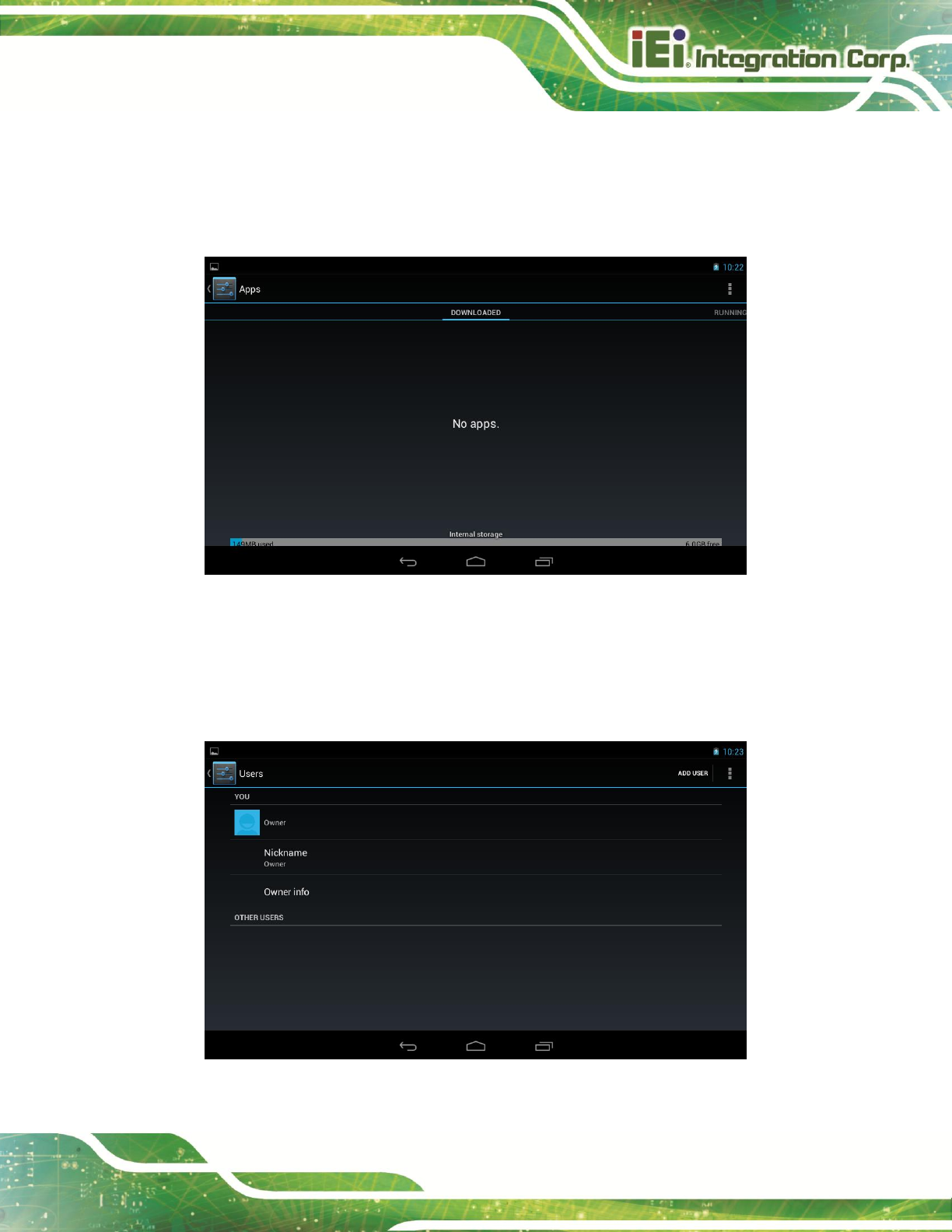
4.4.5 Apps
The Apps menu displays the applications installed in the device, and allows users to
manage them.
Figure 4-17: Apps Menu
4.4.6 Users
The Users menu allows the user to configure the owner information.
Figure 4-18: Users Menu
IKARPC-07A-A9 In-vehicle Panel PC
Page 40
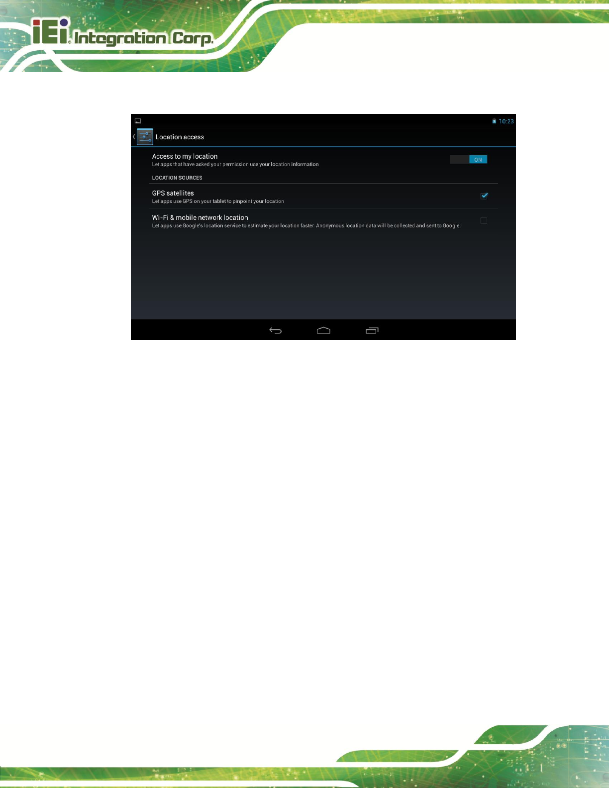
4.4.7 Location Access
Figure 4-19: Location Access Menu
Use the Location access menu to configure the following items.
Access to my location
lets apps obtain the user’s location information.
GPS satellites
allows apps to use the GPS in the device to pinpoint the user’s location. This
item is available only when the Access to my location item is enabled.
Wi-Fi & mobile network location
allows the apps to use Google’s location service to estimate the user’s
location. This item is available only when the Access to my location item is
enabled.

IKARPC-07A-A9 In-vehicle Panel PC
Page 41
4.4.8 Security
Figure 4-20: Security Menu
Use the Security menu to configure the following items.
Screen lock
sets up the way to unlock the screen.
Owner info
configures the owner information to display on the lock screen.
Make passwords visible
allows the device to show password when typing.
Device administrators
displays or deactivates the device administrators.
Unknown sources
allows installation of applications from unknown sources.
Trusted credentials
displays trusted CA certificates.
Install from SD card
allows the user to install certificates from the SD card.
IKARPC-07A-A9 In-vehicle Panel PC
Page 42
4.4.9 Language & Input
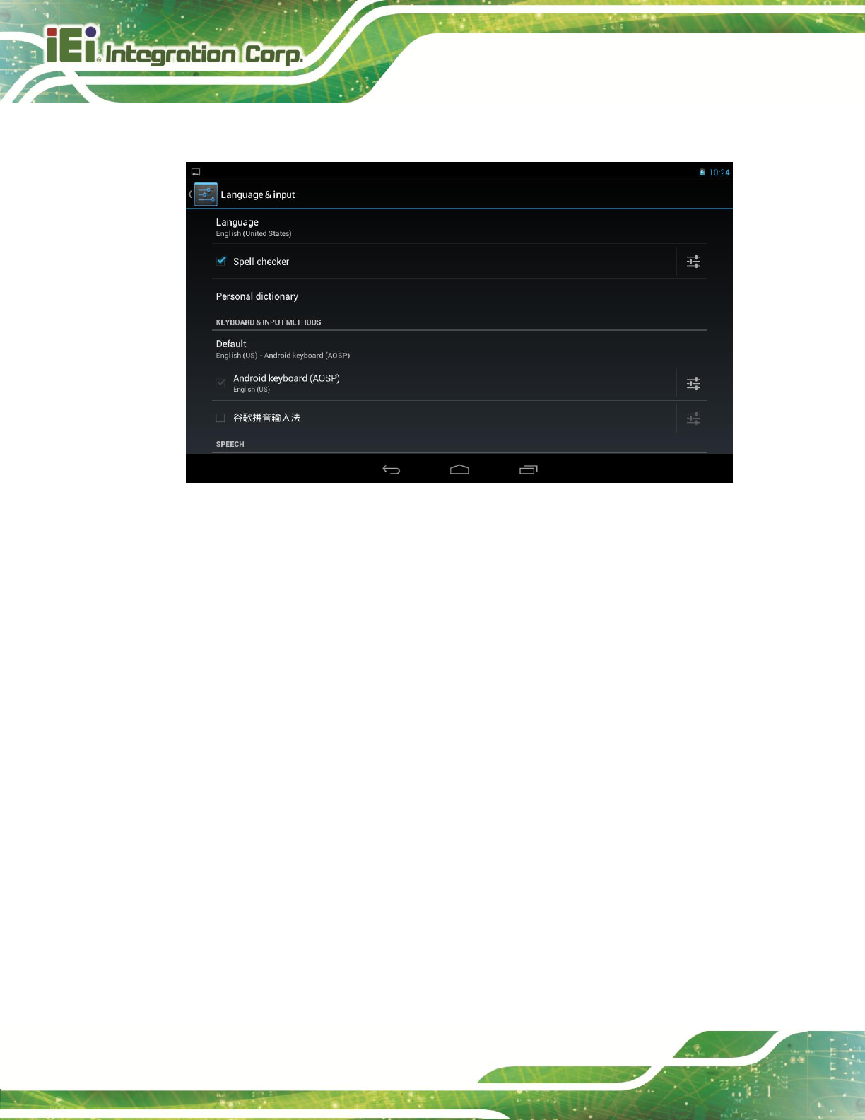
Figure 4-21: Language & Input Menu
Use the Language & input menu to configure the following items.
Language
sets up the language for IKARPC-07A-A9.
Spell checker
allows the user to enable the spell checking function and configure its
settings.
Personal dictionary
configures the user dictionary.
KEYBOARD & INPUT METHODS
allows the user to set up the onscreen keyboard.
Text-to-speech output
configures the text-to-speech settings.
Pointer speed
sets up the pointer speed.
IKARPC-07A-A9 In-vehicle Panel PC
Page 43
4.4.10 Backup & Reset
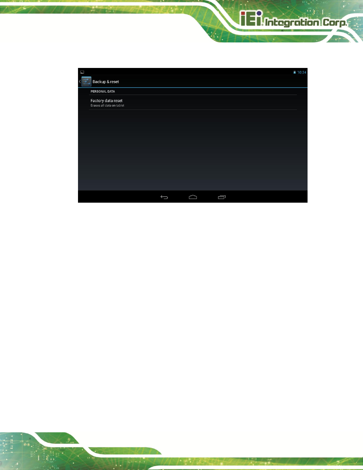
Figure 4-22: Backup & Reset Menu
Use the Back & reset menu to configure the following items.
Factory data reset
erases all data from the internal storage of the IKARPC-07A-A9.
IKARPC-07A-A9 In-vehicle Panel PC
Page 44
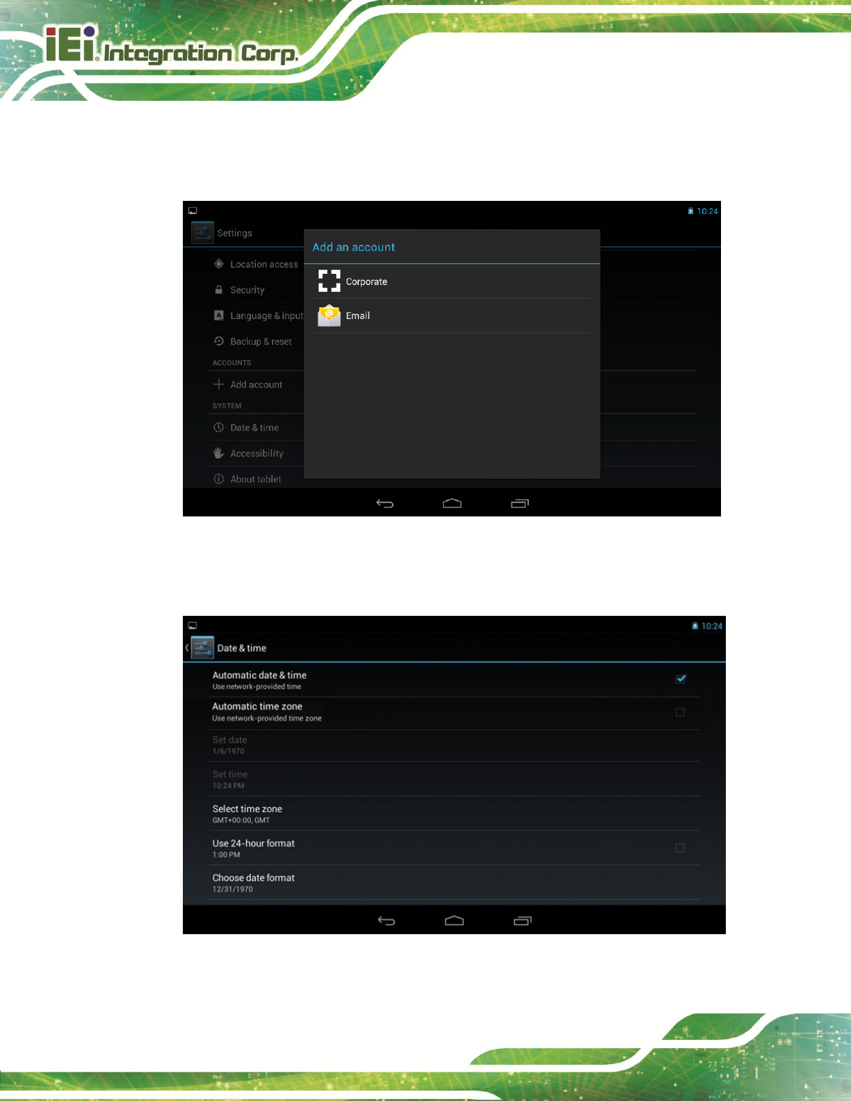
4.4.11 Add account
Tap Add account to start setting up an e-mail or corporate account.
Figure 4-23: Add Account Menu
4.4.12 Date & Time
Figure 4-24: Date & Time Menu
IKARPC-07A-A9 In-vehicle Panel PC
Page 45
Use the Date & time menu to configure the following items.
Automatic date & time
uses the network-provided time.
Automatic time zone
uses the network-provided time zone
Select time zone
sets up the time zone.
Use 24-hour format
uses the 24-hour format.
Choose date format
sets up the date format.
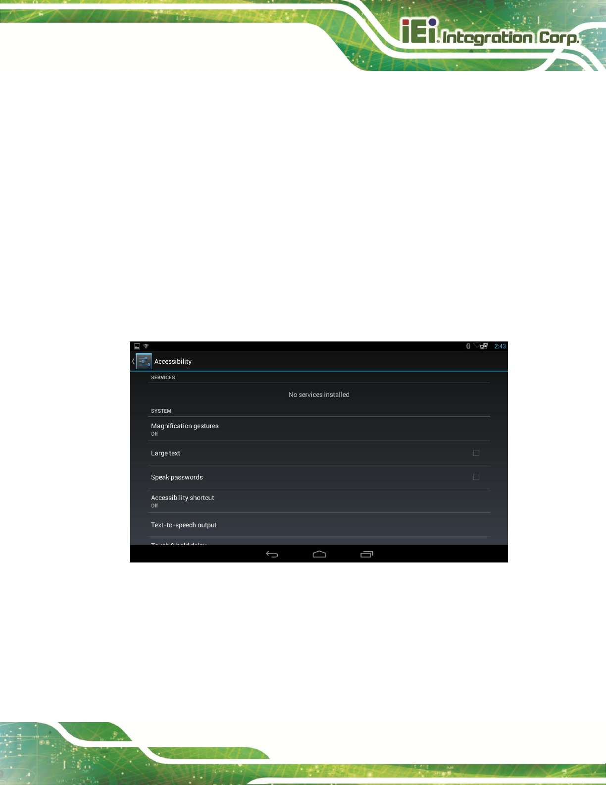
4.4.13 Accessibility
Figure 4-25: Accessibility Menu
Use the Accessibility menu to configure the following items.
Magnification gesture
allows the user to zoom in and out by triple-tapping the screen.
Large text
allows the device to display text in large font.
IKARPC-07A-A9 In-vehicle Panel PC
Page 46
Speak passwords
allows the system to speak passwords.
Text-to-speech output
configures the text-to-speech settings.
Touch & hold delay
configures the touch & hold delay settings.
Enhance web accessibility
allows apps to install scripts from Google that make their web content more
accessible.
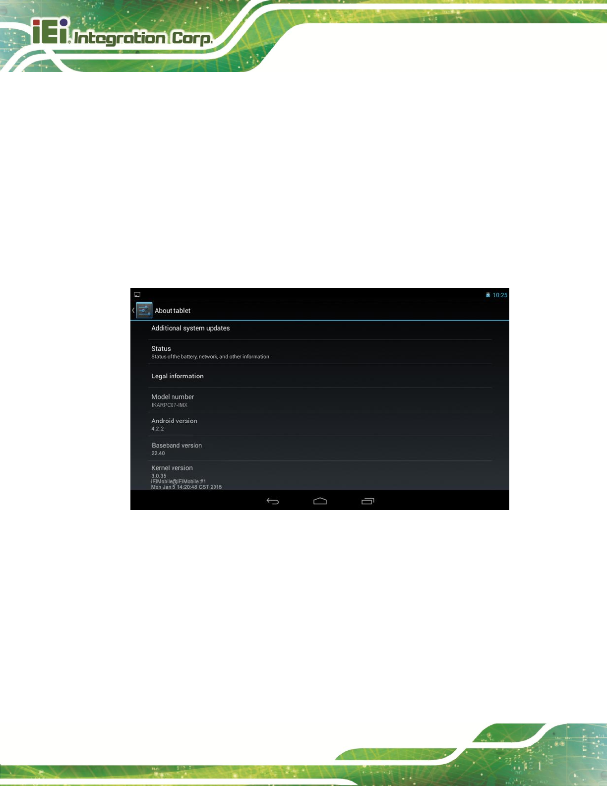
4.4.14 About Tablet
Figure 4-26: About Tablet Menu
Use the About tablet menu to display the following items.
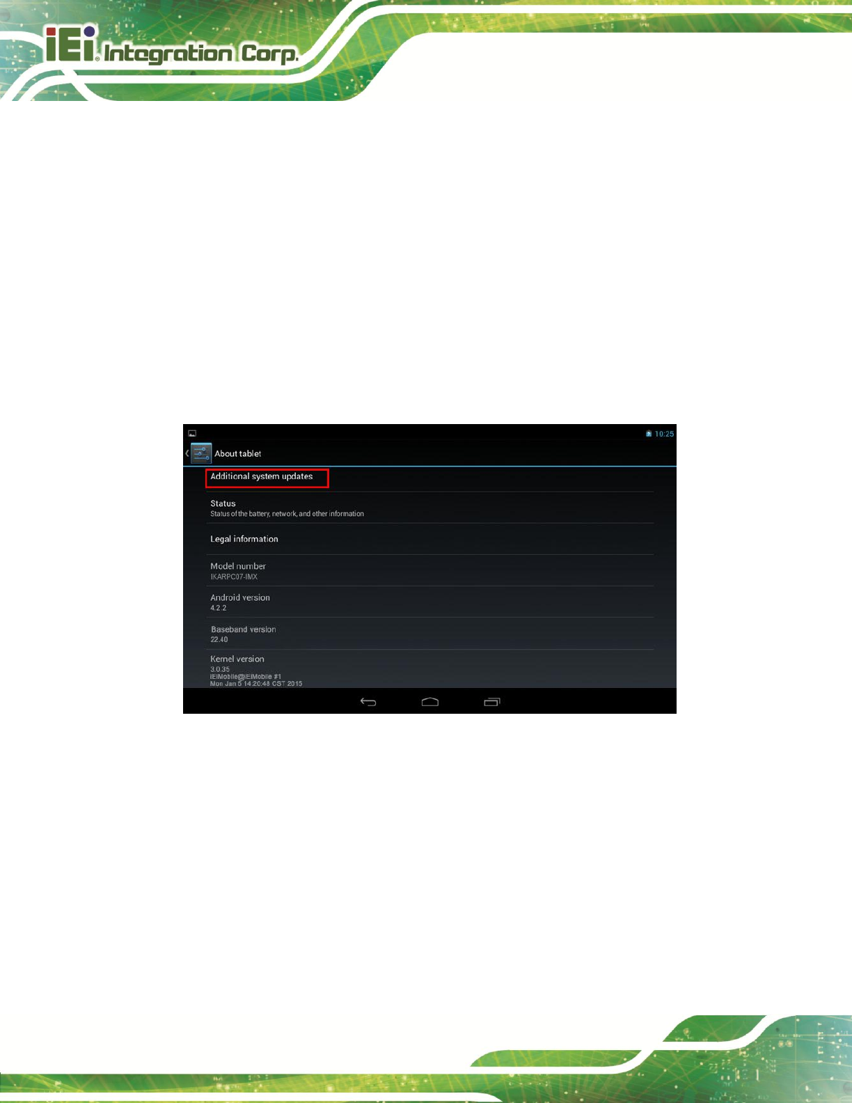
Additional system updates
allows the user to update the system from OTA (over-the-air) or from the SD
card.
Status
displays the status of batteries, network, signal, etc.
Legal information
displays the legal information.

IKARPC-07A-A9 In-vehicle Panel PC
Page 47
Model number
displays the model number.
Android version
displays the Android version.
Baseband version
displays the baseband version.
Kernel version
displays the kernal version.
Build number
displays the device build number.
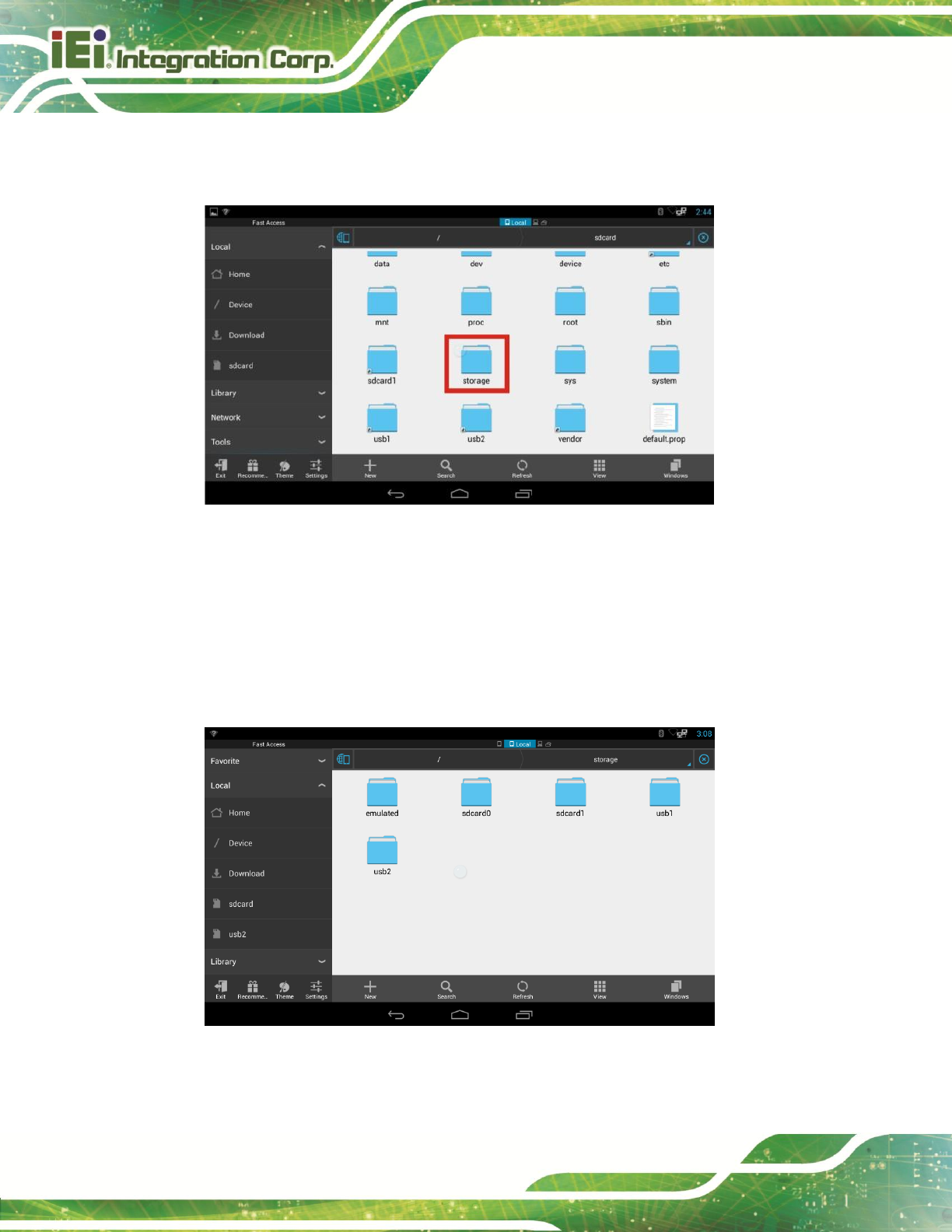
4.5 File Management
The IKARPC-07A-A9 provides a file management tool that allows users to manage files in
the internal storage and external storage devices. Tap ES File Explorer on the application
page to launch it.
Figure 4-27: ES File Explorer Icon
IKARPC-07A-A9 In-vehicle Panel PC
Page 48
The ES File Explorer application user interface appears (Figure 4-28). Tap the storage
folder.
Figure 4-28: ES File Explorer Screen
The user can view all the possible storage devices, including
sdcard0: internal storage of the IKARPC-07A-A9
sdcard1: SD card connected to the IKARPC-07A-A9
usb1: USB storage device connected to the USB host connector on the side
panel. Refer to Figure 1-5 for the connector location.
Figure 4-29: Possible Storage Devices
IKARPC-07A-A9 In-vehicle Panel PC
Page 49
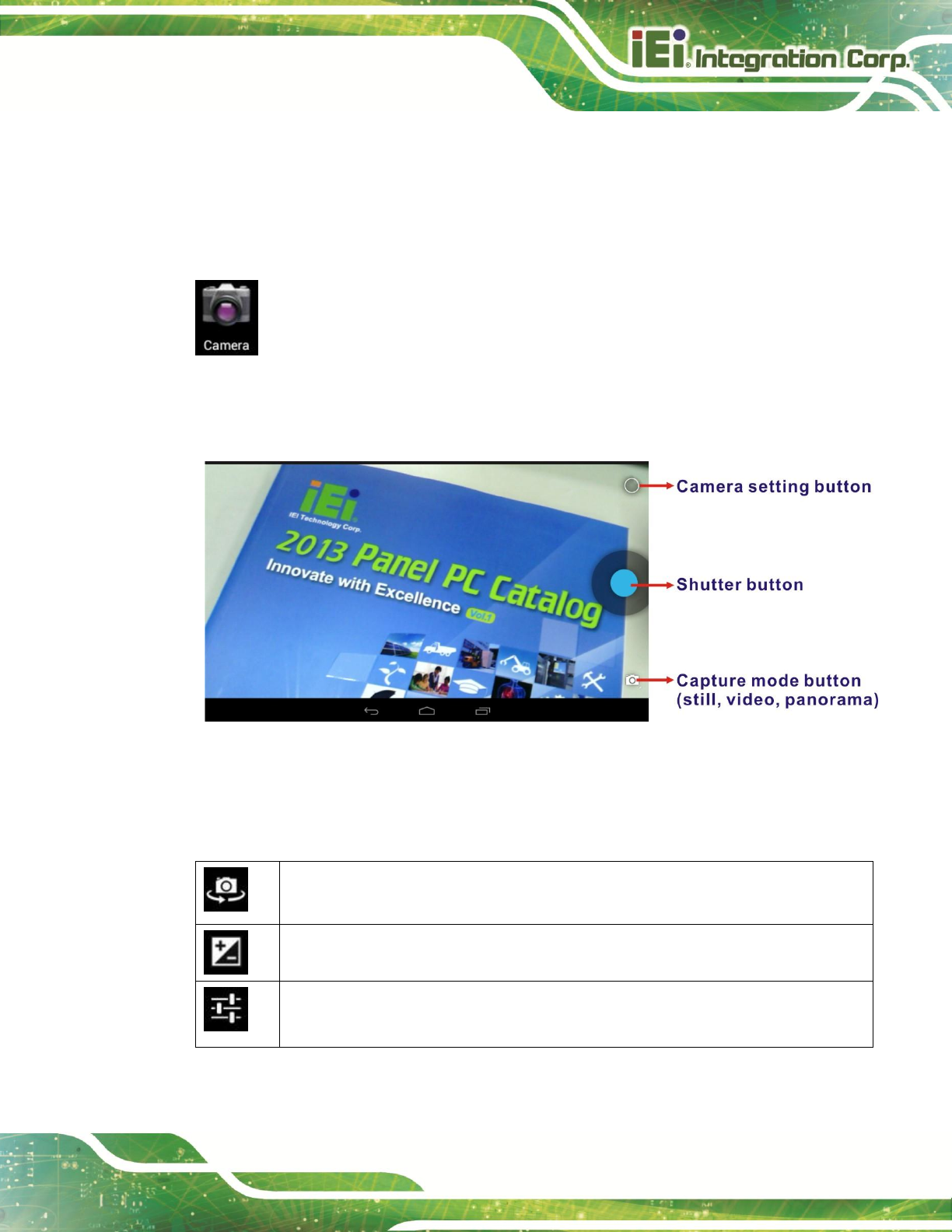
4.6 Camera
The IKARPC-07A-A9 equips with a 5-megapixel front-facing auto-focus camera, and also
accepts a video device through the video input connector on the rear panel. To manage
the built-in camera or the connected video device, tap Camera on the Launcher page.
The user interface of the camera application appears. Figure 4-30 and Table 4-2 describe
each button in detail.
Figure 4-30: Camera Application
After pressing the camera setting button on the top right side, the following three icons will
appear in the middle of the screen. Adjust the settings if necessary.
Switch between the front-facing camera and the video device connected to the video
input connector on the rear panel.
Adjust exposure
Enable or disable image location information.
Adjust the megapixel of the image size.
Table 4-2: Camera Application–Camera Setting Buttons
IKARPC-07A-A9 In-vehicle Panel PC
Page 50
4.7 System Update
If there is a newer version of OS or firmware available, please follow the steps below to
update the system.
Step 3: If choosing to update the OS or firmware from the SD card, save the update file
to an SD card and insert the SD card to the IKARPC-07A-A9 (see Section 3.4
for the SD card installation instruction). The user can also update from OTA
(over-the-air) via Wi-Fi connection.
Step 4: Access the Launcher page and click Settings. Scroll down to select About
Tablet. Then, tap Additional system updates.
Figure 4-31: Additional System Updates
Step 5: The System Update page shows. Select either to update from OTA (over-the-air)
or from the installed SD card.

IKARPC-07A-A9 In-vehicle Panel PC
Page 51
Chapter
5
5 Interface Connectors
IKARPC-07A-A9 In-vehicle Panel PC
Page 52
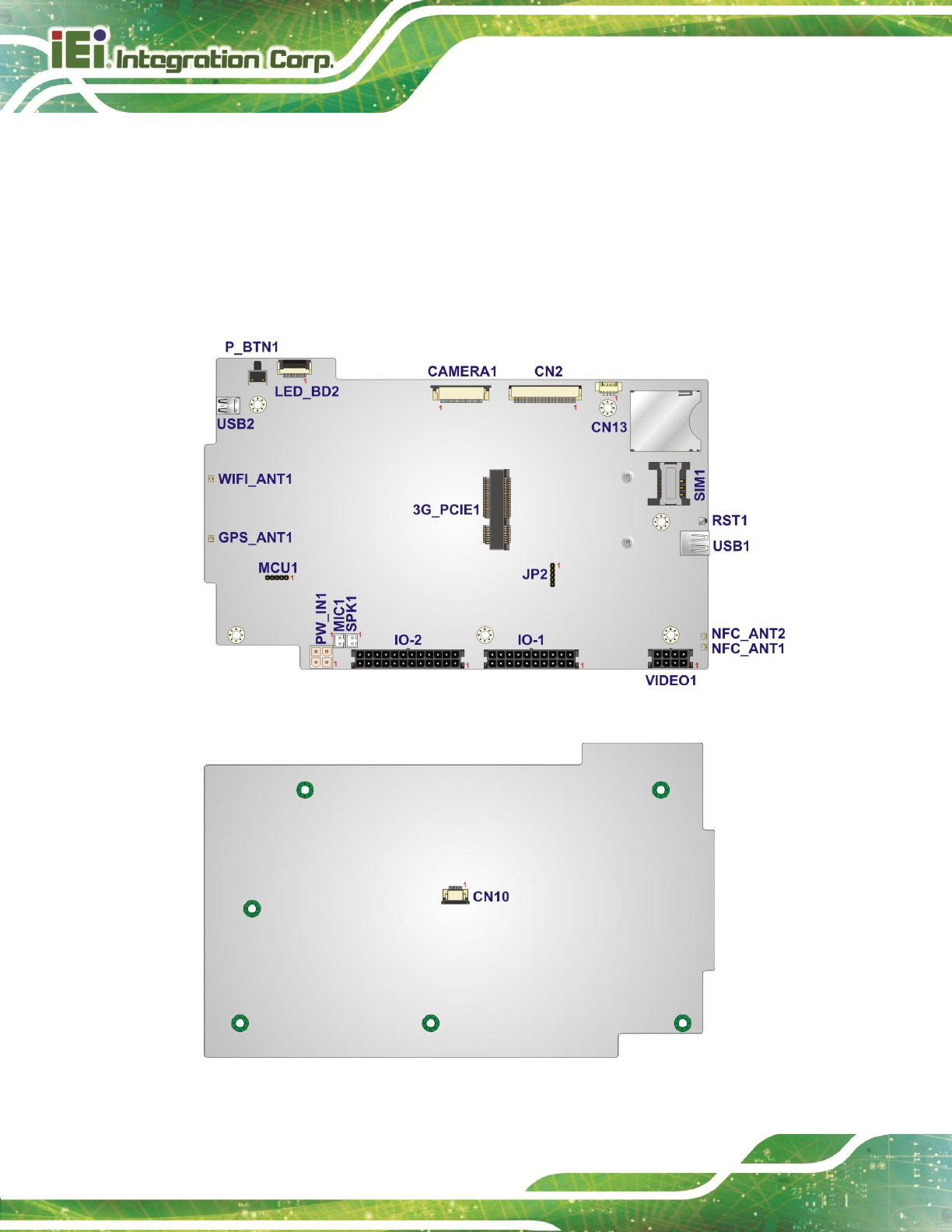
5.1 Peripheral Interface Connectors
The motherboard of the IKARPC-07A-A9 comes with a number of peripheral interface
connectors and configuration jumpers. The connector locations are shown in Figure 5-1
and Figure 5-2. The Pin 1 locations of the on-board connectors are also indicated in the
diagrams below. The connector pinouts for these connectors are listed in the following
sections.
Figure 5-1: Main Board Layout Diagram (Front Side)
Figure 5-2: Main Board Layout Diagram (Solder Side)
IKARPC-07A-A9 In-vehicle Panel PC
Page 53
5.2 Internal Peripheral Connectors
Internal peripheral connectors are found on the motherboard and are only accessible
when the motherboard is outside of the chassis. The table below shows a list of the
peripheral interface connectors on the IKARPC-07A-A9 motherboard. Pinouts of these
connectors can be found in the following sections.
Connector
Type
Label
Camera connector
24-pin FPC
CAMERA1
GPS antenna connector
Antenna connector
GPS_ANT1
LED connector
12-pin FPC
LED_BD2
LVDS connector
40-pin FPC
CN2
Microphone connector
2-pin wafer
MIC1
PCIe Mini card slot for 3.75G module
Full-size PCIe Mini slot
3G_PCIE1
Power button
Push button
P_BTN1
Power input connector
4-pin Molex
PW_IN1
Programming connector
5-pin header
MCU1
JP2
Reset button
Push button
RST1
RFID antenna connector
Antenna connector
NFC_ANT1
NFC_ANT2
SD card socket
SD card socket
CN13
SIM card socket
SIM card socket
SIM1
Speaker connector
2-pin wafer
SPK1
Touch panel connector
8-pin FPC
CN10
USB ports
External USB port
USB1
USB2
Wi-Fi antenna connector
Antenna connector
WIFI_ANT1
Table 5-1: Peripheral Interface Connectors
IKARPC-07A-A9 In-vehicle Panel PC
Page 54
5.2.1 Camera Connector (CAMERA1)
PIN NO.
DESCRIPTION
PIN NO.
DESCRIPTION
1
GND
13
NC
2
CIM_AF2V8
14
CIM_nRST
3
NC
15
NC
4
NC
16
NC
5
GND
17
NC
6
MIPI_D1_P
18
I2C_SDA1
7
MIPI_D1_N
19
I2C_SCL1
8
MIPI_CLK_P
20
CAMERA_PWD
9
MIPI_CLK_N
21
CAMERA_MCLK
10
MIPI_D0_P
22
CIM_IO_1V5
11
MIPI_D0_N
23
CIM_IO1V8
12
NC
24
CIM_A2V8
Table 5-2: Camera Connector (CAMERA1) Pinouts
5.2.2 LED Connector (LED_BD2)
PIN NO.
DESCRIPTION
1
VIO_3V3
2
VIO_3V3
3
VIO_3V3
4
NC
5
I2C_SDA
6
I2C_SCL
7
GND
8
LED_3.5G
9
LED_WLAN
10
LED_BT
11
GND
12
GND
Table 5-3: LED Connector (LED_BD2) Pinouts
IKARPC-07A-A9 In-vehicle Panel PC
Page 55
5.2.3 LVDS Connector (CN2)
PIN NO.
DESCRIPTION
PIN NO.
DESCRIPTION
1
LCM_LEDA
21
LCM_RIN3-
2
LCM_LEDA
22
GND
3
VLCD_VGH
23
LCM_CLK+
4
GND
24
LCM_CLK-
5
GND
25
GND
6
VLCD_VGL
26
LCM_RIN2+
7
GND
27
LCM_RIN2-
8
VLCD_3V3
28
GND
9
LCM_LEDK
29
LCM_RIN1+
10
LCM_LEDK
30
LCM_RIN1-
11
GND
31
GND
12
VCC_LCD_AVDD
32
LCM_RIN0+
13
GND
33
LCM_RIN0-
14
DIMO
34
GND
15
NC
35
VLCD_3V3
16
GND
36
LCM_nRST
17
NC
37
NC
18
NC
38
VLCD_3V3
19
GND
39
VLCD_3V3
20
LCM_RIN3+
40
VLCD_VCOM
Table 5-4: LVDS Connector (CN2) Pinouts
5.2.4 Microphone Connector (MIC1)
PIN NO.
DESCRIPTION
1
MIC_IN_P
2
MIC_IN_N
Table 5-5: Microphone Connector (MIC1) Pinouts
IKARPC-07A-A9 In-vehicle Panel PC
Page 56
5.2.5 Programming Connector (MCU1)
PIN NO.
DESCRIPTION
1
MCLR
2
MCU_PWR
3
GND
4
ICSPCLK2
5
ICSPDAT2
Table 5-6: Programming Connector (MCU1) Pinouts
5.2.6 Programming Connector (JP2)
PIN NO.
DESCRIPTION
1
MCLR#-1
2
5V_OBD
3
GND
4
2580_CLK
5
2580_DAT
Table 5-7: Programming Connector (JP2) Pinouts
5.2.7 Speaker Connector (SPK1)
PIN NO.
DESCRIPTION
1
SPK_OUT_P
2
SPK_OUT_N
Table 5-8: Speaker Connector (SPK1) Pinouts
5.2.8 Touch Panel Connector (CN10)
PIN NO.
DESCRIPTION
1
TH_PWR
2
GND
3
CTP_DM5
4
CTP_DP5

IKARPC-07A-A9 In-vehicle Panel PC
Page 57
5
CTP_RST#
6
I2C_SCL3
7
I2C_SDA3
8
CTP_INTR
Table 5-9: Touch Panel Connector (CN10) Pinouts

IKARPC-07A-A9 In-vehicle Panel PC
Page 58
Appendix
A
A Regulatory Compliance
IKARPC-07A-A9 In-vehicle Panel PC
Page 59
DECLARATION OF CONFORMITY
This equipment is in conformity with the following EU directives:
EMC Directive 2004/108/EC
Low-Voltage Directive 2006/95/EC
RoHS II Directive 2011/65/EU
Ecodesign Directive 2009/125/EC
If the user modifies and/or install other devices in the equipment, the CE conformity
declaration may no longer apply.
If this equipment has telecommunications functionality, it also complies with the
requirements of the R&TTE Directive 1999/5/EC.
English
IEI Integration Corp declares that this equipment is in compliance with the essential
requirements and other relevant provisions of Directive 1999/5/EC.
Български [Bulgarian]
IEI Integration Corp. декларира, че този оборудване е в съответствие със
съществените изисквания и другите приложими правила на Директива 1999/5/ЕС.
Česky [Czech]
IEI Integration Corp tímto prohlašuje, že tento zařízení je ve shodě se základními
požadavky a dalšími příslušnými ustanoveními směrnice 1999/5/ES.
Dansk [Danish]
IEI Integration Corp erklæ rer herved, at følgende udstyr overholder de væ sentlige krav
og øvrige relevante krav i direktiv 1999/5/EF.
Deutsch [German]
IEI Integration Corp, erklärt dieses Gerät entspricht den grundlegenden Anforderungen
und den weiteren entsprechenden Vorgaben der Richtlinie 1999/5/EU.
Eesti [Estonian]
IEI Integration Corp deklareerib seadme seadme vastavust direktiivi 1999/5/EÜ
põhinõuetele ja nimetatud direktiivist tulenevatele teistele asjakohastele sätetele.

IKARPC-07A-A9 In-vehicle Panel PC
Page 60
Español [Spanish]
IEI Integration Corp declara que el equipo cumple con los requisitos esenciales y
cualesquiera otras disposiciones aplicables o exigibles de la Directiva 1999/5/CE.
Ελληνική [Greek]
IEI Integration Corp ΔΗΛΩΝΕΙ ΟΣΙ ΕΞΟΠΛΙΜΟ ΤΜΜΟΡΦΩΝΕΣΑΙ ΠΡΟ ΣΙ
ΟΤΙΩΔΕΙ ΑΠΑΙΣΗΕΙ ΚΑΙ ΣΙ ΛΟΙΠΕ ΥΕΣΙΚΕ ΔΙΑΣΑΞΕΙ ΣΗ ΟΔΗΓΙΑ
1999/5/ΕΚ.
Français [French]
IEI Integration Corp déclare que l'appareil est conforme aux exigences essentielles et
aux autres dispositions pertinentes de la directive 1999/5/CE.
Italiano [Italian]
IEI Integration Corp dichiara che questo apparecchio è conforme ai requisiti essenziali
ed alle altre disposizioni pertinenti stabilite dalla direttiva 1999/5/CE.
Latviski [Latvian]
IEI Integration Corp deklarē, ka iekārta atbilst būtiskajām prasībām un citiem ar to
saistītajiem noteikumiem Direktīvas 1999/5/EK.
Lietuvių [Lithuanian]
IEI Integration Corp deklaruoja, kad šis įranga atitinka esminius reikalavimus ir kitas
1999/5/EB Direktyvos nuostatas.
Nederlands [Dutch]
IEI Integration Corp dat het toestel toestel in overeenstemming is met de essentiële
eisen en de andere relevante bepalingen van richtlijn 1999/5/EG.
Malti [Maltese]
IEI Integration Corp jiddikjara li dan prodott jikkonforma mal-ħtiġijiet essenzjali u ma
provvedimenti oħrajn relevanti li hemm fid-Dirrettiva 1999/5/EC.
Magyar [Hungarian]
IEI Integration Corp nyilatkozom, hogy a berendezés megfelel a vonatkozó alapvetõ
követelményeknek és az 1999/5/EC irányelv egyéb elõírásainak.
Polski [Polish]
IEI Integration Corp oświadcza, że wyrobu jest zgodny z zasadniczymi wymogami oraz
pozostałymi stosownymi postanowieniami Dyrektywy 1999/5/EC.
Português [Portuguese]
IEI Integration Corp declara que este equipamento está conforme com os requisitos
essenciais e outras disposições da Directiva 1999/5/CE.
IKARPC-07A-A9 In-vehicle Panel PC
Page 61
Româna [Romanian]
IEI Integration Corp declară că acest echipament este in conformitate cu cerinţele
esenţiale şi cu celelalte prevederi relevante ale Directivei 1999/5/CE.
Slovensko [Slovenian]
IEI Integration Corp izjavlja, da je ta opreme v skladu z bistvenimi zahtevami in ostalimi
relevantnimi določili direktive 1999/5/ES.
Slovensky [Slovak]
IEI Integration Corp týmto vyhlasuje, že zariadenia spĺňa základné požiadavky a všetky
príslušné ustanovenia Smernice 1999/5/ES.
Suomi [Finnish]
IEI Integration Corp vakuuttaa täten että laitteet on direktiivin 1999/5/EY oleellisten
vaatimusten ja sitä koskevien direktiivin muiden ehtojen mukainen.
Svenska [Swedish]
IEI Integration Corp förklarar att denna utrustningstyp står I överensstämmelse med de
väsentliga egenskapskrav och övriga relevanta bestämmelser som framgår av direktiv
1999/5/EG.

IKARPC-07A-A9 In-vehicle Panel PC
Page 62
FCC WARNING
This device complies with Part 15 of the FCC Rules. Operation is subject to the following
two conditions: (1) this device may not cause harmful interference, and(2) this device
must accept any interference received, including interference that may cause undesired
operation.
NOTE: This equipment has been tested and found to comply with the limits for a Class B
digital device, pursuant to part 15 of the FCC Rules. These limits are designed to
provide reasonable protection against harmful interference in a residential installation.
This equipment generates, uses and can radiate radio frequency energy and, if not
installed and used in accordance with the instructions, may cause harmful interference
to radio communications.
However, there is no guarantee that interference will not occur in a particular installation.
If this equipment does cause harmful interference to radio or television reception, which
can be determined by turning the equipment off and on, the user is encouraged to try to
correct the interference by one or more of the following measures:
—Reorient or relocate the receiving antenna.
—Increase the separation between the equipment and receiver.
—Connect the equipment into an outlet on a circuit different from that to which the
receiver is connected.
—Consult the dealer or an experienced radio/ TV technician for help.
You are cautioned that any change or modifications to the equipment not expressly
approve by the party responsible for compliance could void your authority to operate
such equipment.
IMPORTANT NOTE:
FCC Radiation Exposure Statement:
This equipment complies with FCC radiation exposure limits set forth for an uncontrolled
environment. This equipment should be installed and operated with minimum distance
20cm between the radiator & your body.

IKARPC-07A-A9 In-vehicle Panel PC
Page 63
Appendix
B
B Safety Precautions

IKARPC-07A-A9 In-vehicle Panel PC
Page 64
WARNING:
The precautions outlined in this chapter should be strictly followed.
Failure to follow these precautions may result in permanent damage to
the IKARPC-07A-A9.
B.1 Safety Precautions
Please follow the safety precautions outlined in the sections that follow:
B.1.1 General Safety Precautions
Please ensure the following safety precautions are adhered to at all times.
Follow the electrostatic precautions outlined below whenever the
IKARPC-07A-A9 is opened.
Make sure the power is turned off and the power cord is disconnected
whenever the IKARPC-07A-A9 is being installed, moved or modified.
Do not apply voltage levels that exceed the specified voltage range.
Doing so may cause fire and/or an electrical shock.
Electric shocks can occur if the IKARPC-07A-A9 chassis is opened when
the IKARPC-07A-A9 is running.
Do not drop or insert any objects into the ventilation openings of the
IKARPC-07A-A9.
If considerable amounts of dust, water, or fluids enter the
IKARPC-07A-A9, turn off the power supply immediately, unplug the power
cord, and contact the IKARPC-07A-A9 vendor.
DO NOT:
o Drop the IKARPC-07A-A9 against a hard surface.
o Strike or exert excessive force onto the LCD panel.
o Touch any of the LCD panels with a sharp object
o In a site where the ambient temperature exceeds the rated temperature

IKARPC-07A-A9 In-vehicle Panel PC
Page 65
B.1.2 Anti-static Precautions
WARNING:
Failure to take ESD precautions during the installation of the
IKARPC-07A-A9 may result in permanent damage to the
IKARPC-07A-A9 and severe injury to the user.
Electrostatic discharge (ESD) can cause serious damage to electronic components,
including the IKARPC-07A-A9. Dry climates are especially susceptible to ESD. It is
therefore critical that whenever the IKARPC-07A-A9 is opened and any of the electrical
components are handled, the following anti-static precautions are strictly adhered to.
Wear an anti-static wristband: Wearing a simple anti-static wristband can
help to prevent ESD from damaging any electrical component.
Self-grounding: Before handling any electrical component, touch any
grounded conducting material. During the time the electrical component is
handled, frequently touch any conducting materials that are connected to the
ground.
Use an anti-static pad: When configuring or working with an electrical
component, place it on an antic-static pad. This reduces the possibility of ESD
damage.
Only handle the edges of the electrical component: When handling the
electrical component, hold the electrical component by its edges.
IKARPC-07A-A9 In-vehicle Panel PC
Page 66
B.1.3 Product Disposal
CAUTION:
Risk of explosion if battery is replaced by an incorrect type. Only
certified engineers should replace the on-board battery.
Dispose of used batteries according to instructions and local
regulations.
Outside the European Union - If you wish to dispose of used electrical and
electronic products outside the European Union, please contact your local
authority so as to comply with the correct disposal method.
Within the European Union:
EU-wide legislation, as implemented in each Member State, requires that
waste electrical and electronic products carrying the mark (left) must be
disposed of separately from normal household waste. This includes
monitors and electrical accessories, such as signal cables or power cords.
When you need to dispose of your display products, please follow the
guidance of your local authority, or ask the shop where you purchased the product. The
mark on electrical and electronic products only applies to the current European Union
Member States.
Please follow the national guidelines for electrical and electronic product disposal.
B.2 Maintenance and Cleaning Precautions
When maintaining or cleaning the IKARPC-07A-A9, please follow the guidelines below.
B.2.1 Maintenance and Cleaning
Prior to cleaning any part or component of the IKARPC-07A-A9, please read the details
below.

IKARPC-07A-A9 In-vehicle Panel PC
Page 67
Except for the LCD panel, never spray or squirt liquids directly onto any other
components. To clean the LCD panel, gently wipe it with a piece of soft dry
cloth or a slightly moistened cloth.
The interior of the IKARPC-07A-A9 does not require cleaning. Keep fluids
away from the IKARPC-07A-A9 interior.
Be cautious of all small removable components when vacuuming the
IKARPC-07A-A9.
Turn the IKARPC-07A-A9 off before cleaning the IKARPC-07A-A9.
Never drop any objects or liquids through the openings of the
IKARPC-07A-A9.
Be cautious of any possible allergic reactions to solvents or chemicals used
when cleaning the IKARPC-07A-A9.
Avoid eating, drinking and smoking within vicinity of the IKARPC-07A-A9.
B.2.2 Cleaning Tools
Some components in the IKARPC-07A-A9 may only be cleaned using a product
specifically designed for the purpose. In such case, the product will be explicitly mentioned
in the cleaning tips. Below is a list of items to use when cleaning the IKARPC-07A-A9.
Cloth – Although paper towels or tissues can be used, a soft, clean piece of
cloth is recommended when cleaning the IKARPC-07A-A9.
Water or rubbing alcohol – A cloth moistened with water or rubbing alcohol
can be used to clean the IKARPC-07A-A9.
Using solvents – The use of solvents is not recommended when cleaning the
IKARPC-07A-A9 as they may damage the plastic parts.
Vacuum cleaner – Using a vacuum specifically designed for computers is
one of the best methods of cleaning the IKARPC-07A-A9. Dust and dirt can
restrict the airflow in the IKARPC-07A-A9 and cause its circuitry to corrode.
Cotton swabs - Cotton swaps moistened with rubbing alcohol or water are
excellent tools for wiping hard to reach areas.
Foam swabs - Whenever possible, it is best to use lint free swabs such as
foam swabs for cleaning.

IKARPC-07A-A9 In-vehicle Panel PC
Page 68
Appendix
C
C OBD-II Reader
Command
IKARPC-07A-A9 In-vehicle Panel PC
Page 69
C.1 Select a Chip Initial Mode: UpDate F/W or RUN F/W
AP sends query
F/W receives query
1
2
3
4
5
6
7
8
9
10
11
12
13
14
15
16
17
18
19
Enter Boot
Mode
0x3
1
Enter RUN
Mode
0x3
0
C.2 Boot Mode
Launch AP: P1618QP (Pic18F Bootloader )
Baud Rate:115200
C.3 Run Mode
Any mode in Run mode
AP sends query
F/W receives query
1
2
3
4
5
6
7
8
9
10
11
12
13
14
15
16
17
18
19
Enter
OBD-II
$
M
A
0x0
A
0x0
D
Enter
CAN
Standard
V2.2.B
$
M
B
0x0
A
0x0
D
Request
mode &
version
$
M
R
0x0
A
0x0
D
IKARPC-07A-A9 In-vehicle Panel PC
Page 70
F/W returns (after receiving query)
1
2
3
4
5
6
7
8
9
10
11
12
13
14
15
16
17
18
19
Select a
mode to
send
$
M
0
0x0
0
Ver
(1)
0x1
0
Ver
(2)
0x0
6
0x0
A
0x0
D
Tele mode
response
$
M
1
0x0
0
Ver
(1)
0x1
0
Ver
(2)
0x0
6
0x0
A
0x0
D
CAN S
mode
response
$
M
2
0x0
0
Ver
(1)
0x1
0
Ver
(2)
0x0
6
0x0
A
0x0
D
Enter Tele
mode to
respond
$
M
T
0x0
A
0x0
D
Enter CAN
S mode to
respond
$
M
C
0x0
A
0x0
D
IKARPC-07A-A9 In-vehicle Panel PC
Page 71
C.4 Into CAN_Standard V2.2.B (CAN standard)
AP sends query
F/W receives query
1
2
3
4
5
6
7
8
9
10
11
12
13
14
15
16
17
18
19
Sent by
CAN
$
C
T
0x0A
0x0D
Set CAN
baud
$
C
B
xxx Baud
0x00
Reserved
0x0
A
0x0
D
Set to
send by
CAN
$
C
X
0x00
Reserved
TxIDE RTR
B0 B1
DLC
ID(1
)
ID(2
)
ID(3
)
ID(4
)
D1
D2
D3
D4
D5
D6
D7
D8
0x0
A
0x0
D
Setup
menu
$
C
M
M1ID(1)
M1ID(2)
M1I
D(3)
M1I
D(4)
M1
F1I
D(1)
M1F
1ID(
2)
M1
F1I
D(3)
M1F
1ID(
4)
M1
F2I
D(1)
M1F
2ID(
2)
M1F
2ID(
3)
M1
F2I
D(4)
M2I
D(1)
M2I
D(2)
M2I
D(3)
M2I
D(4
)
M2
F1I
D(1)
M2F
1ID(
2)
M2
F1I
D(3)
M2F1ID(4
)
M2F2ID(1)
M2F
2ID(
2)
M2F
2ID(
3)
M2
F2I
D(4)
M3F
3ID(
1)
M3
F3I
D(2)
M3F
3ID(
3)
M3
F3I
D(4)
M3F
4ID(
1)
M3F
4ID(
2)
M3
F4I
D(3)
M3F
4ID(
4)
RxI
DE
xxx
xxx
x
0x0
A
0x0
D
Read
setting
$
C
R
0x0A
0x0D
Setup
read
menu
$
C
G
0x0A
0x0D
F/W returns (after receiving query)
1
2
3
4
5
6
7
8
9
10
11
12
13
14
15
16
17
18
19
Set CAN
baud
complete
$
C
9
0x0A
0x0
D
CAN query
setup
$
C
3
0x0A
0x0
D
IKARPC-07A-A9 In-vehicle Panel PC
Page 72
complete
Menu setup
complete
$
C
4
0x0A
0x0
D
Read query
setup
$
C
5
xxx
Bau
d
TxID
E
RTR
B0
B1
DLC
ID(1)
ID(2)
ID(3)
ID(4)
D1
D2
D3
D4
D5
D6
D7
D8
0x0A
0x0
D
Read menu
setup
$
C
7
M1I
D(1)
M1I
D(2)
M1I
D(3)
M1I
D(4)
M1F
1ID(
1)
M1F
1ID(
2)
M1F
1ID(
3)
M1F
1ID(
4)
M1F
2ID(
1)
M1F
2ID(
2)
M1F
2ID(
3)
M1F
2ID(
4)
M2I
D(1)
M2I
D(2)
M2I
D(3)
M2I
D(4)
M2F
1ID(
1)
M2F
1ID(
2)
M2F
1ID(
3)
M2F
1ID(
4)
M2F
2ID(
1)
M2F
2ID(
2)
M2F
2ID(
3)
M2F
2ID(
4)
M3F
3ID(
1)
M3F
3ID(
2)
M3F
3ID(
3)
M3F
3ID(
4)
M3F
4ID(
1)
M3F
4ID(
2)
M3F
4ID(
3)
M3F
4ID(
4)
RxID
E
xxx
xxxx
0x0A
0x0
D
Read CAN
complete
$
C
6
xxx
Bau
d
IDE
RTR
B0
B1
DLC
ID(1)
ID(2)
ID(3)
ID(4)
D1
D2
D3
D4
D5
D6
D7
D8
0x0A
0x0
D
CAN starts
query
$
C
8
0x0A
0x0
D
CAN query
error
$
C
E
0x0A
0x0
D
CAN query
succeed
$
C
F
0x0A
0x0
D
IKARPC-07A-A9 In-vehicle Panel PC
Page 73
C.5 Into Telematics
F/W:Telematics
AP: Telematics V1.005
AP sends query
F/W receives query
1
2
3
4
5
6
7
8
9
10
11
12
13
14
15
16
17
18
19
Scan all
Z
0
0x0
D
Scan all
Z
0x0
D
Scan
OBD-II
Z
1
0x0
D
Scan J1939
Z
2
0x0
D
Scan FMS
Z
1
0x0
D
OBD-II
input PID-1
A
Mo
de-
1
Mo
de-
2
PI
D-1
PI
D-2
0x0
D
OBD-II
input PID-2
B
Mo
de-
1
Mo
de-
2
PI
D-1
PI
D-2
0x0
D
OBD-II
input PID-3
C
Mo
de-
1
Mo
de-
2
PI
D-1
PI
D-2
0x0
D
OBD-II
input PID-4
D
Mo
de-
1
Mo
de-
2
PI
D-1
PI
D-2
0x0
D
Reserved
E
Reserved
F
Reserved
G
IKARPC-07A-A9 In-vehicle Panel PC
Page 74
Reserved
H
J1939 input
PSPF
I
P
-1
P
-2
P
-1
P
-2
0x0
D
FMS input
PSPF
J
P
-1
P
-2
P
-1
P
-2
0x0
D
Version
Y
0x0
D
F/W returns (after receiving query)
1
2
3
4
5
6
7
8
9
10
11
12
13
14
15
16
17
18
19
No
device is
scanned
Devices
Scanned
IKARPC-07A-A9 In-vehicle Panel PC
Page 75
OBD packet format (ASCII code)
OBD packet has five different format, they are:
1. CAN 11bits 250
2. CAN 29bits 250
3. CAN 11bits 500
4. CAN 29bits 500
5.Scanning
Each format has its input code, they are:
CAN 11bits 250: A
CAN 29bits 250: B
CAN 11bits 500: C
CAN 29bits 500: D
Scanning: Z
Example 1: To get PID=0104 from CAN 29bits 500 format
Input: D0104+CR (Use ASCII code as the input format of the firmware)
Output: CAN 29bits 500,0104 18DAF111 08 0241040000000000+LF+CR
(Use ASCII code as the input format of the firmware)
□ ID number □ Key-in value □ ID □ Len □ Data
Other Information: Data include eight different bytes
Byte 1: Data include some return information. For example,
1. 18DAF110 08 064100BE1B301300
Byte1 is 06 followed by six non-zero values.
2. 18DAF110 08 0341043200000000
Byte1 is 03 followed by three non-zero values.
Byte 2: Mode is related with the Key-in value. For example:
0104 18DAF110 08 0341043200000000
Key-in value is 01, Byte 2 value will change to 41. The main difference is: 0 means to
send out by query side, 4 means to send out by receiver side
Byte 3: PID is the same with the Key-in value. For example:
0104 18DAF110 08 0341043200000000
Key-in value is 04, Byte 3 value will be 04.
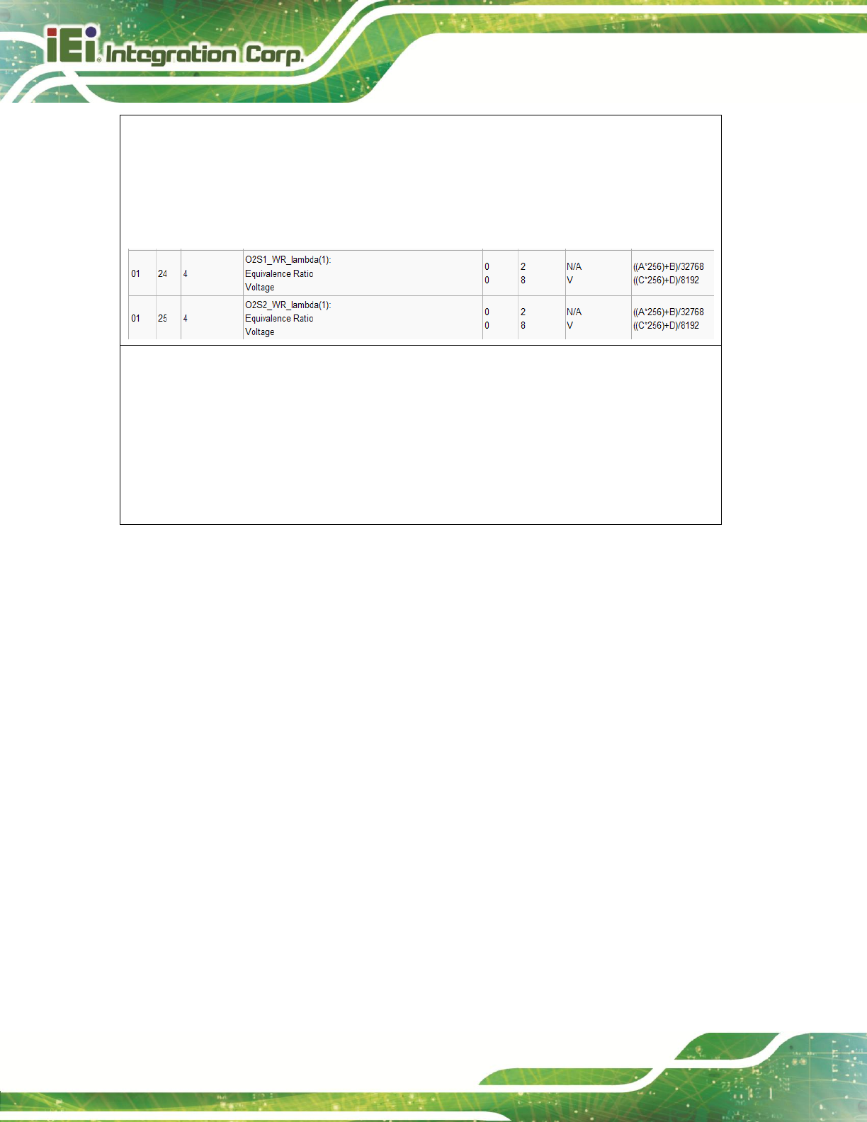
IKARPC-07A-A9 In-vehicle Panel PC
Page 76
Byte 4 define as A. (same with the PID code table on Wikipedia)
Byte 5 define as B. (same with the PID code table on Wikipedia)
Byte 6 define as C. (same with the PID code table on Wikipedia)
Byte 7 define as D. (same with the PID code table on Wikipedia)
As shown below:
Example 2: To Scan
Input: Z+CR (Use ASCII code as the input format of the firmware)
Output: CAN 11bits 250,1 NO SUPPORT+LF+CR
CAN 29bits 250,2 NO SUPPORT+LF+CR
CAN 11bits 500,3 NO SUPPORT+LF+CR
CAN 29bits 500,4 SUPPORT+LF+CR
(Use ASCII code as the input format of the firmware)

IKARPC-07A-A9 In-vehicle Panel PC
Page 77
Appendix
D
D Watchdog Timer
IKARPC-07A-A9 In-vehicle Panel PC
Page 78
NOTE:
The following discussion applies to DOS. Contact IEI support or visit the IEI
website for drivers for other operating systems.
The Watchdog Timer is a hardware-based timer that attempts to restart the system when it
stops working. The system may stop working because of external EMI or software bugs.
The Watchdog Timer ensures that standalone systems like ATMs will automatically
attempt to restart in the case of system problems.
A BIOS function call (INT 15H) is used to control the Watchdog Timer.
INT 15H:
AH – 6FH Sub-function:
AL – 2:
Sets the Watchdog Timer’s period.
BL:
Time-out value (Its unit-second is dependent on the item “Watchdog
Timer unit select” in CMOS setup).
Table D-1: AH-6FH Sub-function
Call sub-function 2 to set the time-out period of Watchdog Timer first. If the time-out value
is not zero, the Watchdog Timer starts counting down. When the timer value reaches zero,
the system resets. To ensure that this reset condition does not occur, calling sub-function
2 must periodically refresh the Watchdog Timer. However, the watchdog timer is disabled
if the time-out value is set to zero.
A tolerance of at least 10% must be maintained to avoid unknown routines within the
operating system (DOS), such as disk I/O that can be very time-consuming.

IKARPC-07A-A9 In-vehicle Panel PC
Page 79
NOTE:
The Watchdog Timer is activated through software. The software
application that activates the Watchdog Timer must also deactivate it
when closed. If the Watchdog Timer is not deactivated, the system will
automatically restart after the Timer has finished its countdown.
EXAMPLE PROGRAM:
; INITIAL TIMER PERIOD COUNTER
;
W_LOOP:
;
MOV AX, 6F02H ;setting the time-out value
MOV BL, 30 ;time-out value is 48 seconds
INT 15H
;
; ADD THE APPLICATION PROGRAM HERE
;
CMP EXIT_AP, 1 ;is the application over?
JNE W_LOOP ;No, restart the application
MOV AX, 6F02H ;disable Watchdog Timer
MOV BL, 0;
INT 15H
;
; EXIT ;

IKARPC-07A-A9 In-vehicle Panel PC
Page 80
Appendix
E
E Hazardous Materials
Disclosure

IKARPC-07A-A9 In-vehicle Panel PC
Page 81
E.1 Hazardous Materials Disclosure Table for IPB Products
Certified as RoHS Compliant Under 2002/95/EC Without
Mercury
The details provided in this appendix are to ensure that the product is compliant with the
Peoples Republic of China (China) RoHS standards. The table below acknowledges the
presences of small quantities of certain materials in the product, and is applicable to China
RoHS only.
A label will be placed on each product to indicate the estimated “Environmentally Friendly
Use Period” (EFUP). This is an estimate of the number of years that these substances
would “not leak out or undergo abrupt change.” This product may contain replaceable
sub-assemblies/components which have a shorter EFUP such as batteries and lamps.
These components will be separately marked.
Please refer to the table on the next page.
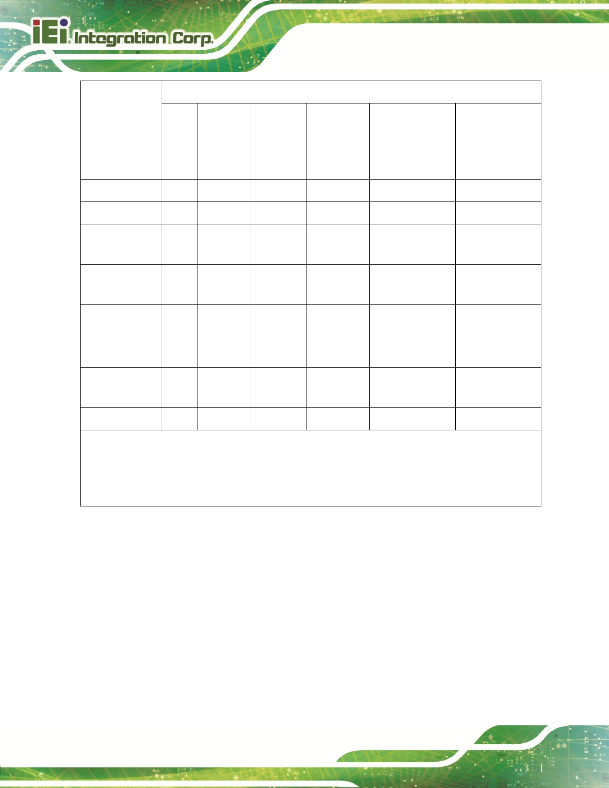
IKARPC-07A-A9 In-vehicle Panel PC
Page 82
Part Name
Toxic or Hazardous Substances and Elements
Lead
(Pb)
Mercury
(Hg)
Cadmium
(Cd)
Hexavalent
Chromium
(CR(VI))
Polybrominated
Biphenyls
(PBB)
Polybrominated
Diphenyl
Ethers
(PBDE)
Housing
O
O
O
O
O
O
Display
O
O
O
O
O
O
Printed Circuit
Board
O
O
O
O
O
O
Metal
Fasteners
O
O
O
O
O
O
Cable
Assembly
O
O
O
O
O
O
Fan Assembly
O
O
O
O
O
O
Power Supply
Assemblies
O
O
O
O
O
O
Battery
O
O
O
O
O
O
O: This toxic or hazardous substance is contained in all of the homogeneous materials for the part is
below the limit requirement in SJ/T11363-2006
X: This toxic or hazardous substance is contained in at least one of the homogeneous materials for
this part is above the limit requirement in SJ/T11363-2006
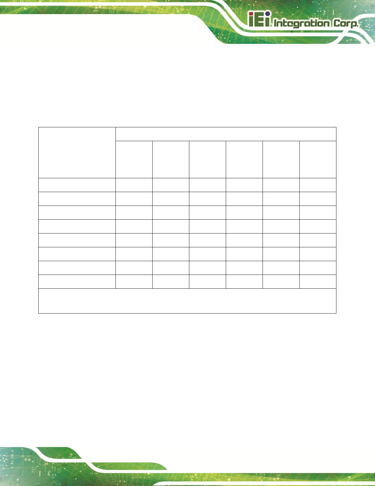
IKARPC-07A-A9 In-vehicle Panel PC
Page 83
此附件旨在确保本产品符合中国 RoHS 标准。以下表格标示此产品中某有毒物质的含量符
合中国 RoHS 标准规定的限量要求。
本产品上会附有”环境友好使用期限”的标签,此期限是估算这些物质”不会有泄漏或突变”的
年限。本产品可能包含有较短的环境友好使用期限的可替换元件,像是电池或灯管,这些元
件将会单独标示出来。
部件名称
有毒有害物质或元素
铅
(Pb)
汞
(Hg)
镉
(Cd)
六价铬
(CR(VI))
多溴联苯
(PBB)
多溴二苯
醚
(PBDE)
壳体
O
O
O
O
O
O
显示
O
O
O
O
O
O
印刷电路板
O
O
O
O
O
O
金属螺帽
O
O
O
O
O
O
电缆组装
O
O
O
O
O
O
风扇组装
O
O
O
O
O
O
电力供应组装
O
O
O
O
O
O
电池
O
O
O
O
O
O
O: 表示该有毒有害物质在该部件所有物质材料中的含量均在 SJ/T11363-2006 标准规定的限量要求以下。
X: 表示该有毒有害物质至少在该部件的某一均质材料中的含量超出 SJ/T11363-2006 标准规定的限量要求。