INID ISORDR RFID User Manual mdoc091201
INID BV RFID mdoc091201
UserManual.wiki
>
INID
>
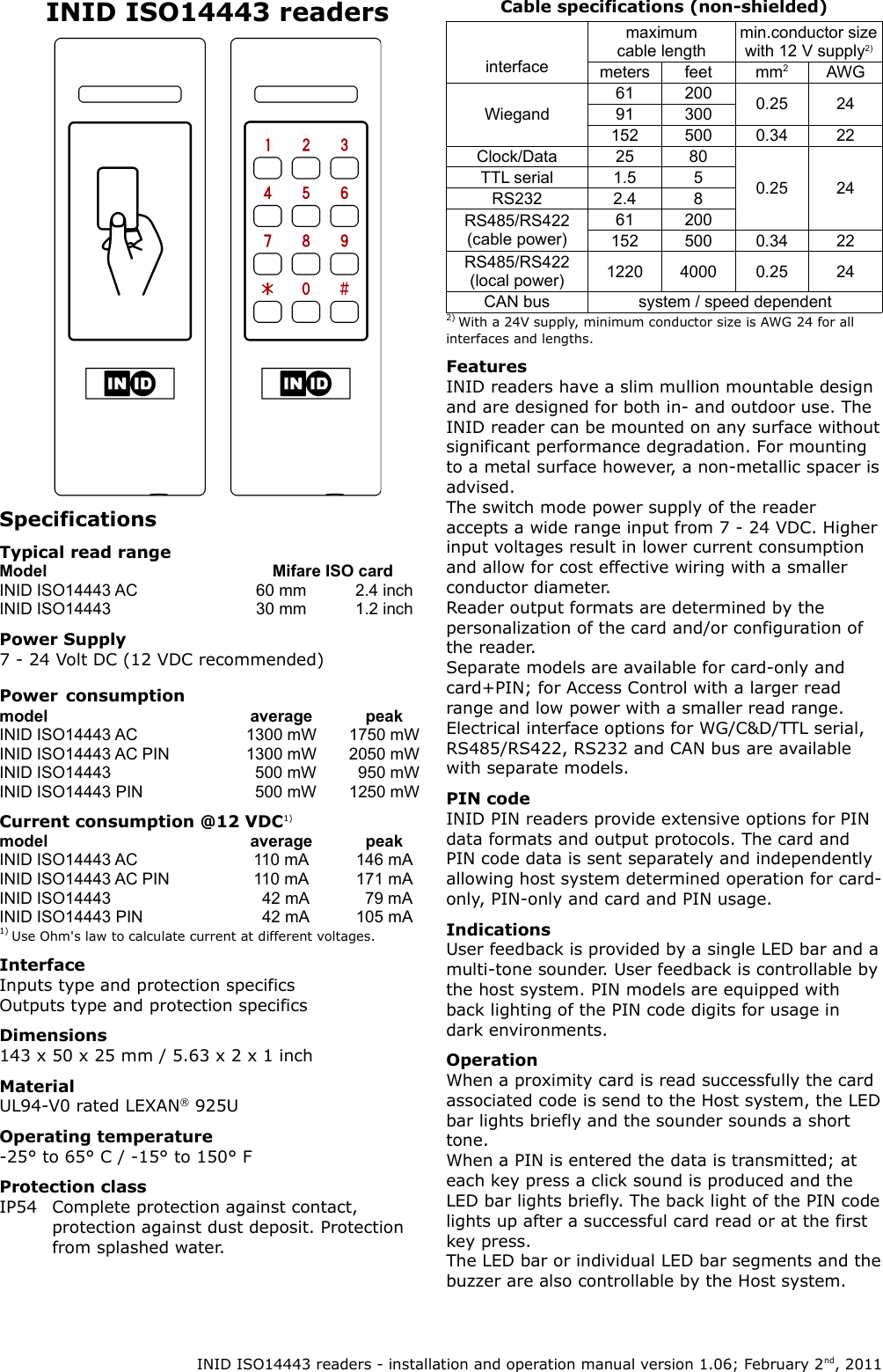
ISORDR User Manual
User manual
Navigation menu
Upload a User Manual
Namespaces
Wiki Guide
HTML
PDF
Info
Views
User Manual
Discussion / Help
Navigation