User manual
INID ISO14443 readers
Specifications
Typical read range
Model Mifare ISO card
INID ISO14443 AC 60 mm 2.4 inch
INID ISO14443 30 mm 1.2 inch
Power Supply
7 - 24 Volt DC (12 VDC recommended)
Power consumption
model average peak
INID ISO14443 AC 1300 mW 1750 mW
INID ISO14443 AC PIN 1300 mW 2050 mW
INID ISO14443 500 mW 950 mW
INID ISO14443 PIN 500 mW 1250 mW
Current consumption @12 VDC1)
model average peak
INID ISO14443 AC 110 mA 146 mA
INID ISO14443 AC PIN 110 mA 171 mA
INID ISO14443 42 mA 79 mA
INID ISO14443 PIN 42 mA 105 mA
1) Use Ohm's law to calculate current at different voltages.
Interface
Inputs type and protection specifics
Outputs type and protection specifics
Dimensions
143 x 50 x 25 mm / 5.63 x 2 x 1 inch
Material
UL94-V0 rated LEXAN® 925U
Operating temperature
-25° to 65° C / -15° to 150° F
Protection class
IP54 Complete protection against contact,
protection against dust deposit. Protection
from splashed water.
Cable specifications (non-shielded)
interface
maximum
cable length
min.conductor size
with 12 V supply2)
meters feet mm2AWG
Wiegand
61 200 0.25 24
91 300
152 500 0.34 22
Clock/Data 25 80
0.25 24
TTL serial 1.5 5
RS232 2.4 8
RS485/RS422
(cable power)
61 200
152 500 0.34 22
RS485/RS422
(local power) 1220 4000 0.25 24
CAN bus system / speed dependent
2) With a 24V supply, minimum conductor size is AWG 24 for all
interfaces and lengths.
Features
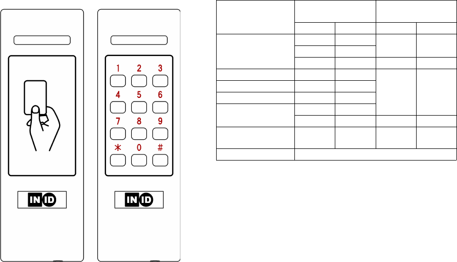
INID readers have a slim mullion mountable design
and are designed for both in- and outdoor use. The
INID reader can be mounted on any surface without
significant performance degradation. For mounting
to a metal surface however, a non-metallic spacer is
advised.
The switch mode power supply of the reader
accepts a wide range input from 7 - 24 VDC. Higher
input voltages result in lower current consumption
and allow for cost effective wiring with a smaller
conductor diameter.
Reader output formats are determined by the
personalization of the card and/or configuration of
the reader.
Separate models are available for card-only and
card+PIN; for Access Control with a larger read
range and low power with a smaller read range.
Electrical interface options for WG/C&D/TTL serial,
RS485/RS422, RS232 and CAN bus are available
with separate models.
PIN code
INID PIN readers provide extensive options for PIN
data formats and output protocols. The card and
PIN code data is sent separately and independently
allowing host system determined operation for card-
only, PIN-only and card and PIN usage.
Indications
User feedback is provided by a single LED bar and a
multi-tone sounder. User feedback is controllable by
the host system. PIN models are equipped with
back lighting of the PIN code digits for usage in
dark environments.
Operation
When a proximity card is read successfully the card
associated code is send to the Host system, the LED
bar lights briefly and the sounder sounds a short
tone.
When a PIN is entered the data is transmitted; at
each key press a click sound is produced and the
LED bar lights briefly. The back light of the PIN code
lights up after a successful card read or at the first
key press.
The LED bar or individual LED bar segments and the
buzzer are also controllable by the Host system.
INID ISO14443 readers - installation and operation manual version 1.06; February 2nd, 2011
Connector Assignments
Wiegand / Clock and Data / TTL serial
500-5000 INID ISO14443 AC reader WG/C&D/TTL
500-5040 INID ISO14443 AC PIN reader WG/C&D/TTL
500-5100 INID ISO14443 reader WG/C&D/TTL
500-5140 INID ISO14443 PIN reader WG/C&D/TTL
1 LED 1 - Green 5 BUZZER RXD
2 LED 2 - Amber 6 TAMPER
3 D1 DATA TXD 7 GND
4 D0 CLOCK TXE 8 POWER
RS485 / RS422
500-5010 INID ISO14443 AC reader RS485/RS422
500-5050 INID ISO14443 AC PIN reader RS485/RS422
500-5110 INID ISO14443 reader RS485/RS422
500-5150 INID ISO14443 PIN reader RS485/RS422
1 LED 1 - Green 5 RS485 n.c. RS422 RX-
2 LED 2 - Amber 6 RS485 n.c. RS422 RX+
3 RS485 TRX+ RS422 TX+ 7 GND
4 RS485 TRX- RS422 TX- 8 POWER
Caution:
floating communication lines may cause spurious emissions.
Ensure all communication lines are properly biased and terminated.
RS232
500-5020 INID ISO14443 AC reader RS232
500-5060 INID ISO14443 AC PIN reader RS232
500-5120 INID ISO14443 reader RS232
500-5160 INID ISO14443 PIN reader RS232
1 LED 1 - Green 5 RTS
2 LED 2 - Amber 6 RXD
3 CTS 7 GND
4 TXD 8 POWER
CAN bus
500-5030 INID ISO14443 AC reader CAN bus
500-5070 INID ISO14443 AC PIN reader CAN bus
500-5130 INID ISO14443 reader CAN bus
500-5170 INID ISO14443 PIN reader CAN bus
1 LED 1 - Green 5 n.c.
2 LED 2 - Amber 6 n.c.
3 CANL 7 GND
4 CANH 8 POWER
Parts list
1 Reader front qty: 1
2 Terminal connector qty: 1
3 Mounting backplate qty: 1
4 Enclosure screw qty: 1
5 Installation sheet qty: 1
Installation instructions
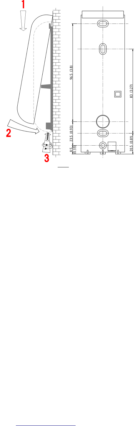
1 Determine an appropriate position for the reader
and drill two holes for mounting the backplate
and one hole for the cable, see diagram for
measurements. Do not mount readers less than
20 cm (8 inches) apart.
2 Pull the cable trough the hole in the backplate
and mount the backplate. Protect the cable
against sharp edges and any damage from
chafing.
3 Remove the terminal connector from the front of
the reader. Prepare the end of the cable and
wires, eliminate any loose or frayed strands. Keep
the wire ends as short as practical.
4 Connect the wires to the connector according to
the reader type. Wire ends, termination resistor
leads and optional permanent links shall be kept
as short as possible.
5 Place the connector on the reader pins.
6 Place the reader front over the hinge of the
backplate and close the reader (see diagram),
keeping the wiring in the lower part of the reader
housing. DO NOT use excessive force, retract the
cable if necessary.
7 Test the reader: apply power and present a valid
card. The LED bar should flash and the sounder
should produce a short tone indicating a
successful read. If the Host system is connected
to LED bar and sounder inputs these should
follow the functionality of the Host system.
8 The reader front should now be secured to the
backplate using the supplied enclosure screw.
Certifications
CE, FCC
FCC ID: YAB-ISOACRDR (model 50XX)
YAB-ISORDR (model 51XX)
Compliance statement
This device complies with part 15 of the FCC Rules.
Operation is subject to the following two conditions:
1) this device may not cause harmful interference, and
2) this device must accept any interference received,
including interference that may cause undesired
operation.
Warning (part 15.21)
Changes or modifications not expressly approved by the
party responsible for compliance could void the user’s
authority to operate the equipment.
This in particular is applicable for the antenna which has
been delivered with the reader.
Consult your National Authority if any authorization
is needed for this product.
INID ISO14443 readers - installation and operation manual version 1.06; February 2nd, 2011
INID BV
Kollenbergweg 78c
1101AV Amsterdam Zuidoost
The Netherlands
Phone: +31 (0)20 6967 441
Web: www.inid-readers.com
For mounting, use only flat head screws with a
maximum shank size of 4 mm (5/32”, #7)