IPS Group IPS2007SSPM Parking Meter with Data Collection User Manual MK5 Manual
IPS Group Inc. Parking Meter with Data Collection MK5 Manual
Users Manual
IP
S
Us
e
V
ersi
S
Singl
e
e
r’s M
a
on 1.0
I
All infor
m
e
-Spac
e
a
nual
I
PS GROUP, In
c
m
ation containe
d
e
Parki
c
. – M5 Manual
(
d
herein is consi
d
ng Me
t
(
Ver. 1.0)
d
ered confidenti
a
t
er M5:
560
1
E-mail: s
Web: htt
a
l
IP
S
1
Oberlin Dri
San Die
g
Phone: (8
5
upport@ips
g
p://www.ips
g
S
Group, In
c
i
ve, Suite 1
0
g
o, CA 921
2
5
8) 404-06
0
g
roupinc.co
m
g
roupinc.co
m
1
c
.
0
0
2
1
0
7
m
m

INFORMATION TO USER
This device complies with Part 15 of the FCC Rules. Operation is subject to the following two
conditions: (1) This device may not cause harmful interference, and (2) This device must accept
any interference received, including interference that may cause undesired operation.
This equipment has been tested and found to comply with the limits for Class B Digital Device,
pursuant to Part 15 of the FCC Rules. These limits are designed to provide reasonable protection
against harmful interference in a residential installation. This equipment generates and can radiate
radio frequency energy and, if not installed and used in accordance with the instructions, may cause
harmful interference to radio communications. However, there is no guarantee that interference will
not occur in a particular installation. If this equipment does cause harmful interference to radio or
television reception, which can be determined by turning the equipment off and on, the user is
encouraged to try to correct the interference by one or more of the following measures.
• Reorient or relocate the receiving antenna
• Increase the separation between the equipment and receiver
Any changes or modifications not expressly approved by the party responsible for compliance could
void the user’s authority to operate the equipment

IPS GROUP, Inc. – M5 Manual (Ver. 1.0)
All information contained herein is considered confidential
2
TABLE OF CONTENTS
INTRODUCTION ............................................................................................................... 4
BASIC METER OPERATION ............................................................................................ 5
Turning the Meter On and Off ..................................................................................... 5
Coins ........................................................................................................................... 5
Credit Cards ................................................................................................................ 5
Smart Cards ................................................................................................................ 6
PARKING METER FEATURES ........................................................................................ 7
Display ........................................................................................................................ 8
Idle/Expired ........................................................................................................ 9
Paid .................................................................................................................... 9
Faulty ................................................................................................................ 10
Prepay .............................................................................................................. 11
Payment Not Accepted ..................................................................................... 11
LEDs ......................................................................................................................... 11
No Parking/After Hours .................................................................................... 11
Idle/Expired ...................................................................................................... 11
Paid .................................................................................................................. 12
Out of Order ..................................................................................................... 12
Keypad ...................................................................................................................... 12
Diagnostics Button .................................................................................................... 13
Card Entry Slot / Card Payment ................................................................................ 13
Coin Entry Slot .......................................................................................................... 13
Payment Method Decal ............................................................................................. 14
Solar Panel ................................................................................................................ 14
Coin Validator ............................................................................................................ 14
RFID .......................................................................................................................... 14
Main Screen .............................................................................................................. 16
Faults ........................................................................................................................ 16
Coin Test ................................................................................................................... 17
Card Test .................................................................................................................. 17
Communications Test (Comms Test) ........................................................................ 18
Fault Logging ............................................................................................................ 19
Meter Swap ............................................................................................................... 19
Voltages .................................................................................................................... 20
Sleep ......................................................................................................................... 21
ACCESS CARDS ............................................................................................................ 22
Meter Diagnostics Card ............................................................................................. 22
Maintenance (Meter Credit) Card .............................................................................. 22
Coin Collection Card ................................................................................................. 22
HOW TO … ..................................................................................................................... 23
Clear a Coin Jam ...................................................................................................... 23
Clear a Card Jam ...................................................................................................... 24
Replace the Battery ................................................................................................... 24
Replace the Keypad .................................................................................................. 26
Replace the Coin Slot ............................................................................................... 26
Force a meter update ................................................................................................ 26
INDEX ............................................................................................................................. 26
A.Parts of the Meter ................................................................................................ 27

IPS GROUP, Inc. – M5 Manual (Ver. 1.0)
All information contained herein is considered confidential
3
Meter Mechanism ............................................................................................. 27
Circuit Boards / Internal Electronics ................................................................. 28
Top Cover (Model 795) .................................................................................... 29
Top Cover (Model 147/ Model 132) .................................................................. 30
B. Error Status Codes .............................................................................................. 31
C.Troubleshooting ................................................................................................... 32
Power ............................................................................................................... 32
Coin Issues ....................................................................................................... 32
Communication Issues ..................................................................................... 32
D.Cleaning and General Maintenance .................................................................... 33

IPS GROUP, Inc. – M5 Manual (Ver. 1.0)
All information contained herein is considered confidential
4
INTRODUCTION
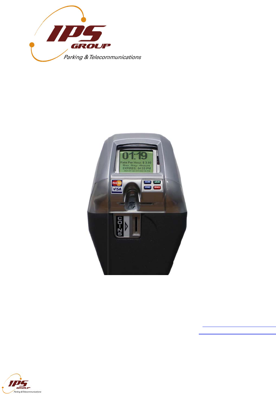
The IPS Single Space Parking Meter (SSPM) is a revolutionary product designed to
enhance a city’s current single space parking system by providing additional payment
options (such as credit card), access to real-time data (via web-based management
system), without disruption of current parking meter operations.
The primary features of the IPS credit card enabled single-space parking meters include:
IPS single space parking meters are capable of accepting payment via coins, tokens,
credit cards, debit cards, and smart cards at the meter terminal
IPS single space parking meters are wirelessly networked and connected to a web-
based management system – no additional customer software other than an Internet
browser shall be required. The meter communicates in a similar fashion to a cell
phone, and makes calls under a number of scenarios including: (1) credit card use,
(2) fault notification, or (3) schedule daily call-in
IPS single-space parking meters use a solar panel and rechargeable battery-pack to
provide ongoing power and backup power
IPS single-space parking Management System can wirelessly notify parking
operations staff of any meter faults via a text message, email, or both
IPS single-space parking Management System provides a variety of reports detailing
financial, technical, and administrative functions via a single web-portal, including but
not limited to credit card reconciliation, cash collection reports, coin box level (% full),
and GPS location of meters. (Please refer to the management system user manual
for complete details)
While the meter does provide a number of advanced features, it functions very similarly
to current electronic single-space parking meters, making implementation of this system
easy and intuitive.
Enclosed in this manual you will find everything you need to acquaint yourself with the
primary operating features of this meter, as well as the basic maintenance activities that
you will encounter. IPS welcomes customer feedback as part of the evolution of this
product, so if you have any questions or concerns, please contact IPS directly:
Phone: (858) 404-0607
Email: support@ipsgroupinc.com
BA
S
Tur
n
To t
u
to th
e
shou
turns
To t
u
the
k
mete
in sl
e
Coi
n
To
m
1
2
3
Cre
d
To
m
1
2
3
4
5
Eve
n
proc
e
S
IC MET
E
n
ing the M
e
u
rn the met
e
e
battery c
o
ld turn on
a
on.
u
rn the met
e
k
eypad until
r diagnostic
e
ep mode (t
u
n
s
ake a paym
. Insert coi
n
. Display s
h
. Metering
d
it Cards
ake a paym
. Insert cre
. Choose
a
. Press th
e
‘Cancel’
b
. Wait for
v
. Metering
if the pay
m
e
ss the pay
m
I
All infor
m
E
R OPE
R
e
ter On an
e
r on, first
m
o
nnector) is
a
utomaticall
y
e
r off, hold
d
the display
s card, go t
o
u
rns meter
o
ent with a c
o
n
s and/or to
h
ows paid ti
begins onc
e
ent with a c
r
dit card and
a
mount of ti
m
e
green ‘OK’
b
utton to voi
d
v
erification.
begins onc
e
m
ent is not c
o
m
ent, and gi
v
I
PS GROUP, In
c
m
ation containe
d
R
ATION
d Of
f
m
ake sure th
a
inserted ov
e
y
. If not, in
s
d
own the di
a
is off. An a
o
the SLEE
P
o
ff as well).
o
in, follow t
h
kens into th
e
me and exp
e
payment i
s
r
edit or debi
t
quickly re
m
m
e using blu
button onc
e
d
the transa
e
payment i
s
o
nfirmed, b
y
v
e the indic
a
c
. – M5 Manual
(
d
herein is consi
d
a
t the jump
e
e
r both pin
s
s
ert any car
d
a
gnostics b
u
dditional w
a
P
display s
c
h
ese steps:
e
coin slot.
iration time.
s
complete.
t
card, follo
w
m
ove it.
e buttons (
+
e
desired ti
m
ction.
s
complete.
y
pressing t
h
a
ted parkin
g
(
Ver. 1.0)
d
ered confidenti
a
e
r (the smal
s
. Once this
d
into the
c
u
tton (Plea
s
a
y to turn th
c
reen and p
r
w
s these st
e
+
for more ti
m
m
e is displa
y
h
e OK butto
n
g
time.
a
l
l black plas
t
is connect
e
c
ard slot un
t
s
e refer to p
h
e meter off
r
ess OK to
p
e
ps:
m
e, - for les
s
y
ed on the
s
n
, the mete
r
t
ic piece ne
x
e
d, the met
e
t
il the displ
a
age 7) belo
w
is to use t
h
p
ut the met
e
s
time).
s
creen or r
e
r
will time o
u
5
x
t
e
r
a
y
w
h
e
e
r
e
d
u
t,

IPS GROUP, Inc. – M5 Manual (Ver. 1.0)
All information contained herein is considered confidential
6
Smart Cards
To make a payment with a smart card, follow these steps:
1. Insert the card chip-side up. The meter will display the remaining balance on the
card.
2. Choose amount of time using blue buttons (+ for more time, - for less time).
3. Press ‘OK’ once desired time is displayed on the screen or ‘Cancel’ to void the
transaction. Follow the instructions on the screen and do not remove the smart
card until instructed to do so. The screen will display the amount deducted from
the user’s smart card as well as the remaining balance.
4. Metering begins when ‘OK’ is pressed.
If a card is left inside the meter, the meter will alert the motorist with a series of beeps. If
it is not removed, the meter will report a card jam.
PA
R
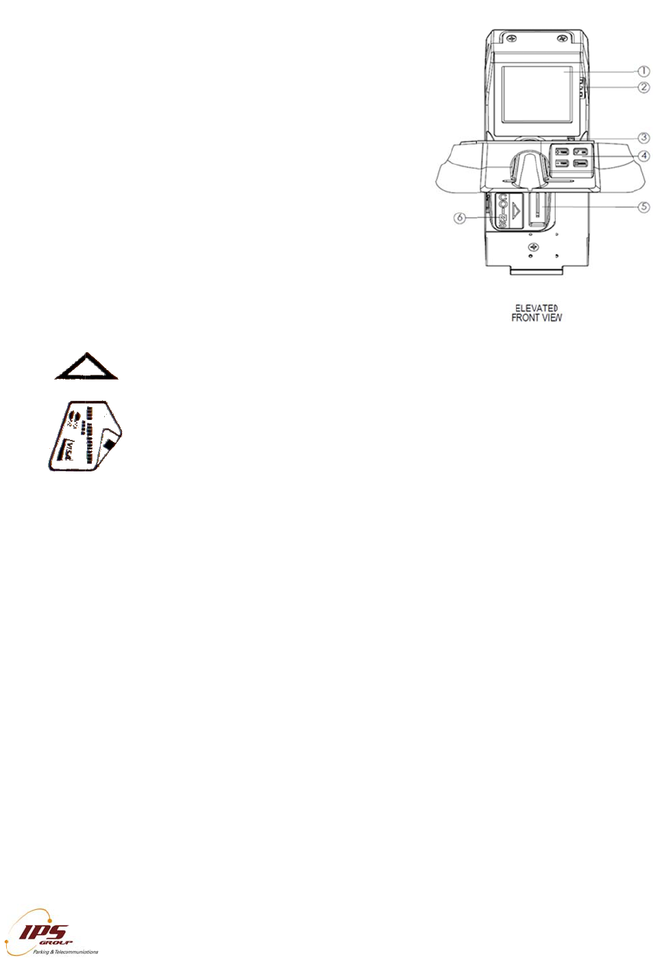
MK5
Part
D
1. Di
s
2. L
E
3. Di
a
4. C
a
5. C
o
6. C
o
7. S
o
8. C
o
R
KING M
E
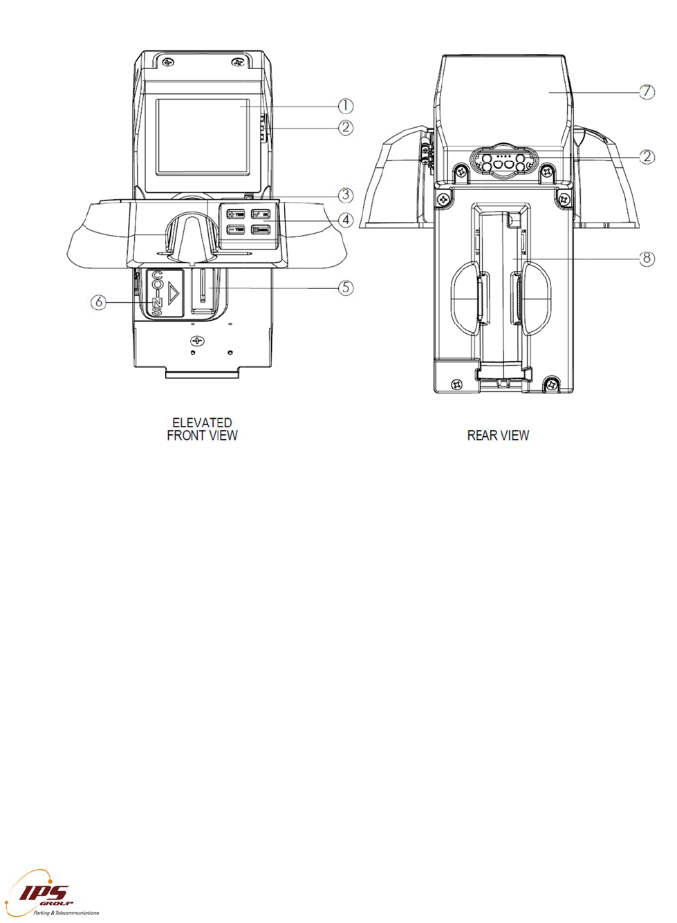
Parking M
e
D
escription
s
s
play
E
Ds
a
gnostic Bu
t
a
rd Entry Sl
o
o
in Entry Sl
o
o
in Decal
o
lar Panel
o
in Validator
I
All infor
m
E
TER FE
e
ter Featur
e
s
t
ton
o
t with Keyp
a
o
t
with Anti-Fi
I
PS GROUP, In
c
m
ation containe
d
ATURES
e
s
a
d
shing
c
. – M5 Manual
(
d
herein is consi
d
(
Ver. 1.0)
d
ered confidenti
a
a
l
7
IPS GROUP, Inc. – M5 Manual (Ver. 1.0)
All information contained herein is considered confidential
8
Display
The display is designed to be simple and user friendly, while providing key information to
both the motorist and enforcement officers. The M5 LCD is 160 X 160 pixels versus the
M3 display screen which was 132 X 64. The messages displayed on the backlit LCD are
fully programmable to provide rate information, parking time limits, and time remaining
on the meter. With the M5 screen, there is now the capability to have images as well
(See below example). Alternating screens allow for a variety of programming options.
The displayed messages can be updated remotely at any time via the web-based
management system.
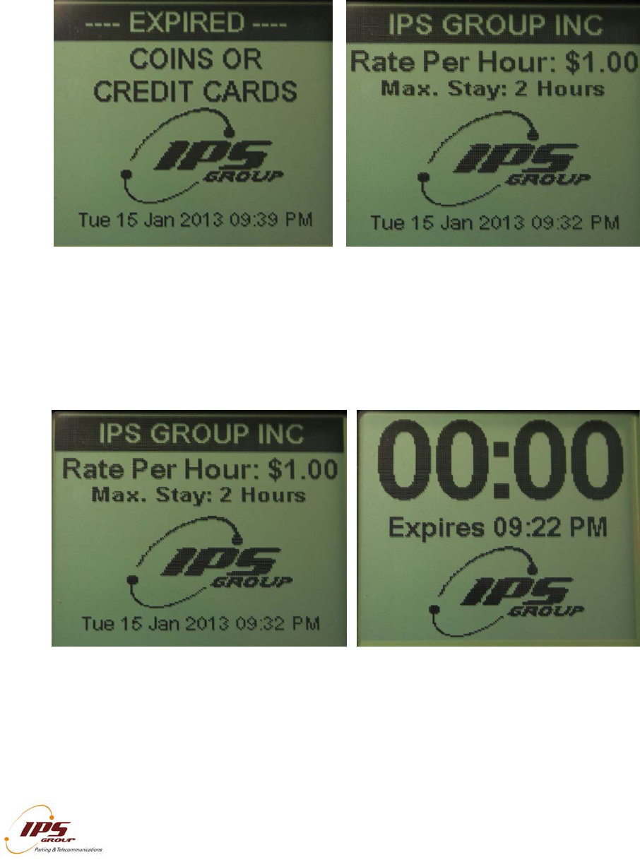
The meter operates in one of the following five states:
Idle/Expired
Paid
Faulty
Prepay
No Payment Accepted
The following images and descriptions highlight the default message settings.
IPS GROUP, Inc. – M5 Manual (Ver. 1.0)
All information contained herein is considered confidential
9
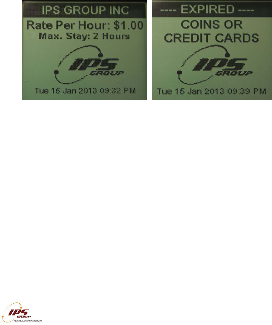
Idle/Expired
An expired meter alternates between displaying the rate and time limit information as
well as the available payment options. (Please see images on following page)
Paid
A paid meter displays the rate and time limit information while the alternate screen
shows the remaining time (in the HH:MM format) and the expiration time. An optional
setting in the management system is available to display negative time during grace
mode or once the meter is expired.
IPS GROUP, Inc. – M5 Manual (Ver. 1.0)
All information contained herein is considered confidential
10
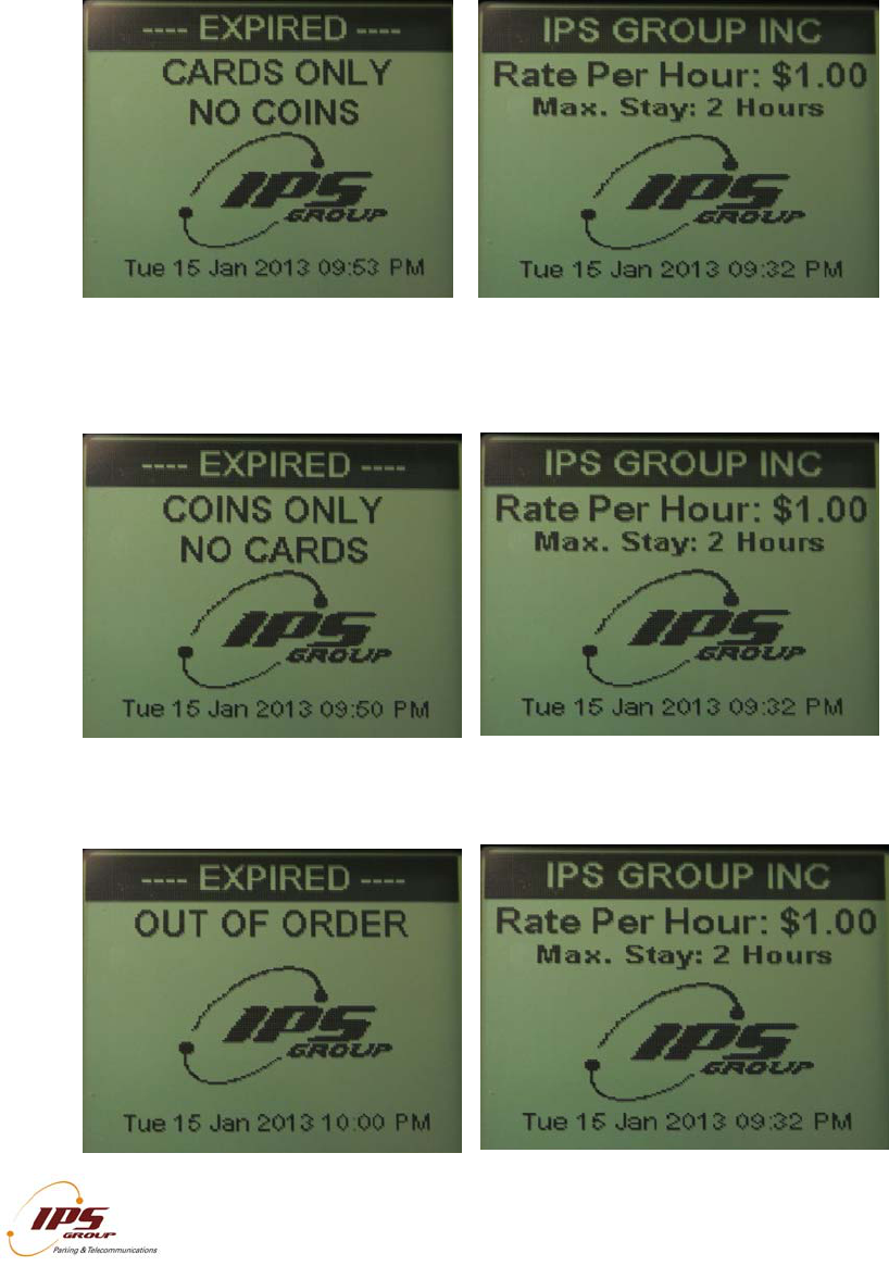
Faulty
There are three types of meter faults that will be displayed: Cards Only, Coins Only,
and Out of Order.
When a coin jam is detected, credit cards will still be available as a payment option:
When a card jam is detected, coins will still be available as a payment option:
When both payment options are unavailable, the meter will display the message below:
IPS GROUP, Inc. – M5 Manual (Ver. 1.0)
All information contained herein is considered confidential
11
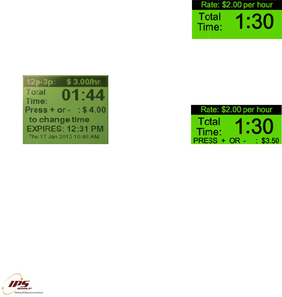
Prepay
The meter may be programmed to accept payment prior to the start of enforcement on
any given day by setting up a prepay period. The actual paid time begins when
enforcement starts but the meter displays the purchased time in addition to the time
between the transaction and the start of enforcement.
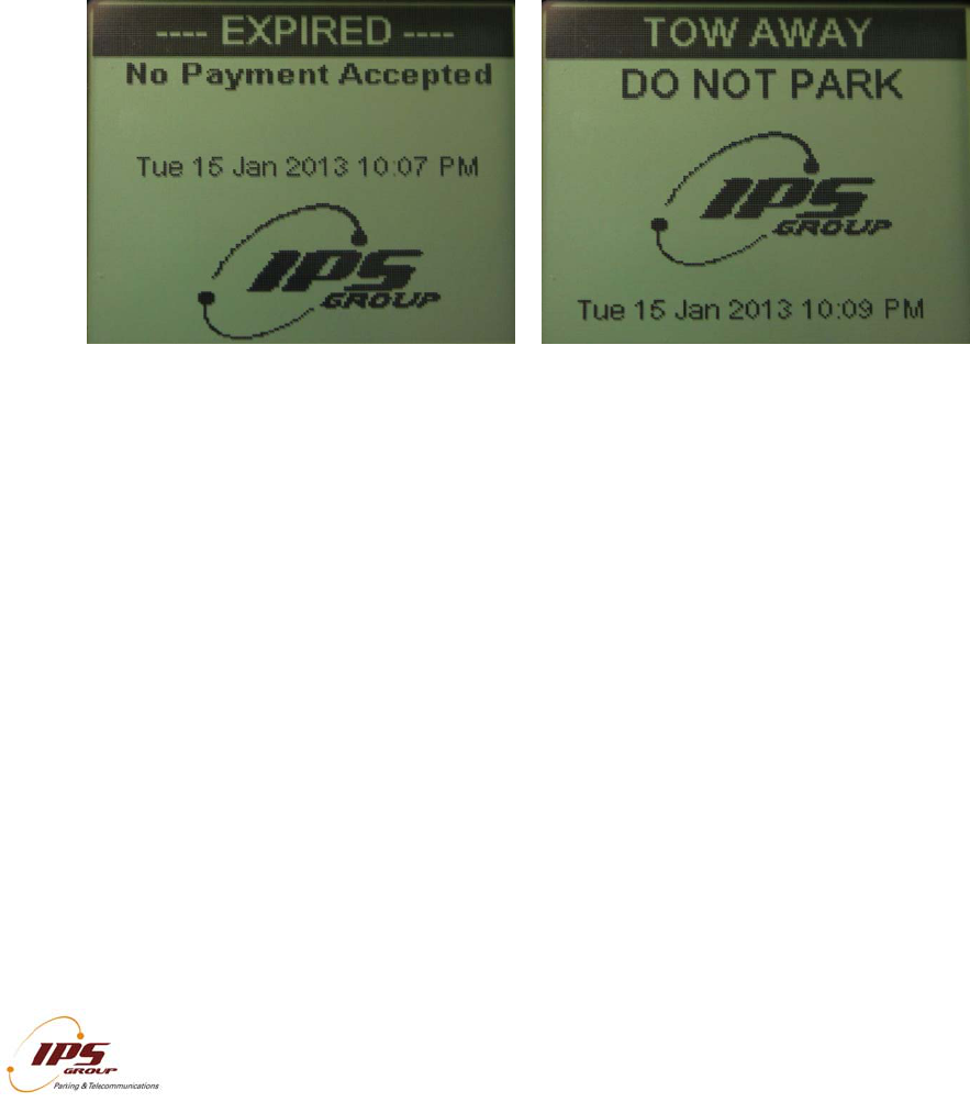
Payment Not Accepted
There are two situations where payment is not accepted: Free Parking and No Parking.
In both cases, when a coin or card is inserted, the meter will ignore the payment and
continue to display the appropriate screen. The Free Parking display is typically used
when parking is not enforced. The No Parking display is used for Tow-Away or Street
Cleaning. The messages for these time periods can be customized as necessary.
LEDs
The LEDs on the back of the meter (below the solar panel) and in the front, to the right of
the display, are intended to indicate the state of the meter. The Hi-Brite LEDs on the
rear allow for easy, in-car meter enforcement while the front LEDs provide a good
indicator for motorists and on-foot enforcement personnel. Typically, these lights are
turned off outside of the hours of enforcement to conserve battery power.
The LEDs on the front and rear of the meter operate the same way. Below is the default
configuration for the LEDs. These operating features can be modified via the
management system.
No Parking/After Hours
The LEDs will be off during non-operational hours.
Idle/Expired
When a meter is expired, the RED LEDs will flash.
Paid
When a meter is paid, the GREEN LEDs will flash

IPS GROUP, Inc. – M5 Manual (Ver. 1.0)
All information contained herein is considered confidential
12
Out of Order
When a meter has a card and/or a coin jam, both AMBER lights will flash.
Keypad
The M5 keypad has four, push buttons: + TIME, - TIME, OK, and CANCEL. They are
used for credit card, debit card, and smart card transactions. After a user inserts and
removes a card, he or she will have the option of adding more time by pressing the +
TIME button, choosing less time with the - TIME button, canceling the transaction using
CANCEL or confirming it by pressing OK. These buttons are not required for coin
transactions. The buttons are also used to navigate through the various diagnostic
options (discussed below).
The IPS M5 uses mechanical buttons rated at more than 200,000 cycles, which
translates into more than 10 years of use. The buttons are also completely
environmentally sealed to prevent moisture from affecting performance. The buttons are
both labeled with symbols, words and are color coded to provide the most intuitive user
experience possible. Additionally, the labels on the buttons are cast (imbedded)
completely through the button so that wear and tear will not result in the label degrading
over time.
Primary Function:
(+) Add more time to a credit card or a smart card transaction in increments defined
within the meter management system.
(-) Subtract more time to a credit card or a smart card transaction in increments defined
within the meter management system.
(OK) Confirm the amount of time to be purchased on a credit card or smart card
transaction.
(X) Cancel a credit card or smart card transaction before the transaction has been
confirmed.
Secondary Function:
(+/-) Buttons can be used to scroll up or down through the meter diagnostics menus.
(OK/X) Used to enter into and exit from specific diagnostics menu capabilities
Tertiary Function:
(OK) If configured, can be used to allow the public access additional information screens
on the meter
**Note as of now, IPS will be sending the card entry slot with keypad as a replacement.
This can be subject to change.
Dia
g
The
the
m
seve
r
a
b
c
Car
d
In or
d
inser
t
This
sma
r
the
m
the c
Coi
n
Moto
is in
s
no a
d
The
size
d
slot i
s
new
coin
s
g
nostics B
u
D
iagnostic
B
m
eter, just
b
r
al uses:
. Press th
e
Mode.
. Press th
e
take time
. Hold do
w
power of
f
d
Entry Sl
o
d
er to pay
w
t
a card int
o
slot will ac
c
r
t cards. T
h
m
agnetic st
r
a
rd entry sl
o
A
ca
any
c
on t
h
n
Entry Sl
o
rists use co
i
s
erted, the a
d
ditional coi
n
coin entry
s
d
to prevent
s
required t
o
c
oin slots.
T
s
) and those
I
All infor
m
u
tton
B
utton is lo
c
b
elow the
k
e
button o
n
e
button o
n
off the met
e
w
n the butt
o
the mete
r
.
o
t / Card P
a
w
ith a credi
o
the card
s
c
ept standa
r
h
e proper w
a
r
ipe down,
o
o
t (see illust
r
rd is also u
s
c
ard into th
e
h
e screen.
o
t
i
ns in the sa
mount o
f
p
a
n
s are adde
d
s
lot can ea
s
certain coi
n
o
adapt to n
e
T
he two (2)
that do not
I
PS GROUP, In
c
m
ation containe
d
c
ated on th
e
k
eypad. T
h
n
ce to acce
n
ce and pr
e
e
r.
o
n for sever
a
a
yment
t card, the
s
lot insert
a
r
d-sized cre
d
a
y to insert
o
n the right
r
ation on th
e
s
ed to turn
e
slot and r
e
me fashion
a
id time app
e
d
, the paid t
i
s
ily be cha
n
n
s from bei
n
e
w coin acc
e
primary op
t
accept $1 c
o
c
. – M5 Manual
(
d
herein is consi
d
e
right side
h
e button h
a
s
s Diagnos
t
e
ss Cancel
a
l seconds
motorist m
u
a
nd remove
d
it, debit, a
n
a card is w
i
hand side
e
left).
the parking
e
move it on
c
as older, co
e
ars on the
i
me is displ
a
n
ged to acc
o
n
g used (su
c
e
ptance poli
t
ions are sl
o
o
ins.
(
Ver. 1.0)
d
ered confidenti
a
of
a
s
tic
to
to
u
st
it.
n
d
ith
of
meter on.
c
e a beep i
s
in-only park
screen.
A
f
t
a
yed on the
o
mmodate
v
c
h as $1 co
cies, pleas
e
o
ts that acc
e
a
l
If the mete
r
s
heard and
k
ing meters.
t
er the met
e
meter.
v
arious coi
n
ins). If an
a
e
contact IP
S
e
pt all coins
1
r
is off, ins
e
text appea
r
When a co
e
r detects th
a
n
sizes or
b
a
lternate co
i
S
to purcha
s
(including
$
3
e
rt
r
s
in
a
t
b
e
in
s
e
$
1
IPS GROUP, Inc. – M5 Manual (Ver. 1.0)
All information contained herein is considered confidential
14
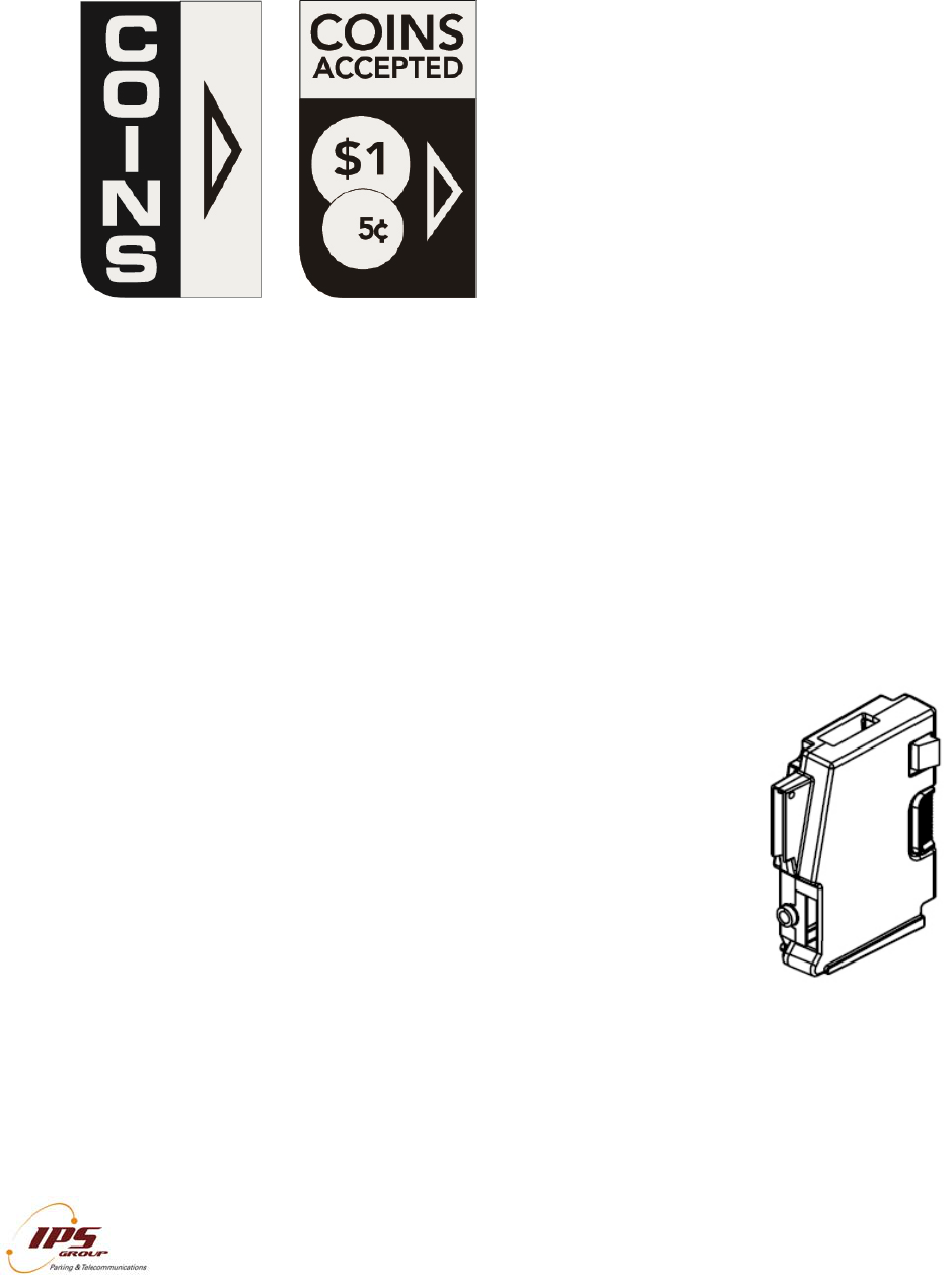
Payment Method Decal
Below are the most commonly used payment method decals. However, customer-
specific decals can be purchased when ordering.
Solar Panel
The solar panel on the back of the meter acts as a continuous source of power for the
meter’s rechargeable battery. The panel should remain unobstructed in order to allow
for maximum light exposure. Although it does not require direct sunlight to be
operational, the solar panel should be free from any graffiti or obstructions in order to
maximize battery life.
Additionally, if a meter will be bagged for longer than a 48 hour period, IPS recommends
that it be turned off to prevent the battery from discharging, as the bag would prevent the
solar panel from receiving light necessary to maintain the battery’s charge.
Coin Validator
The coin validator is a removable component of the meter that
differentiates the coins inserted into the meter based on a variety of
attributes. The validator utilizes optical sensors to detect
blockages caused by both metallic and non-metallic objects. Jams
are reported wirelessly to a distribution list established by the user.
This allows for a more rapid response to affected meters and
results in increased meter uptime and revenue.
A variety of coins or tokens can be programmed into the meter as
required. Additionally, known slugs or coin-like objects commonly
used to defraud the meter can be specifically targeted and
programmed to be rejected. The M5 coin validator has a stronger
connector making it more difficult to secure.
RFI
D
IPS
m
hous
seria
or lo
c
trans
gets
insta
l
any i
locat
i
DIA
The
prev
e
vario
pres
s
butto
men
u
must
Note
avail
a
D
m
eters use
ing to ident
i
l number th
a
c
ation. Eac
mits the RF
linked to t
h
l
lation and
t
nformation.
i
on in the M
a
GNOSTI
C
meter’s di
a
e
nting pote
n
us menus.
s
the CAN
C
n several ti
m
u
item that
h
be pressed
: Each me
t
a
ble than th
e
I
All infor
m
an RFID (
R
i
fy themsel
v
a
t allows th
e
h tag is ass
ID number
w
h
e pole to
w
t
racking of t
It simply
a
a
nagement
S
C
MODE
a
gnostic m
o
n
tial proble
m
To enter a
C
EL button.
m
es until th
h
as no furth
e
before oth
e
t
er is indivi
d
e
ones des
c
I
PS GROUP, In
c
m
ation containe
d
R
adio Freq
u
v
es in the
m
e
meter to
b
igned to a
p
w
ith which i
t
w
hich the R
F
he meter w
a
cts as a li
n
S
ystem.
o
de is a
u
m
s in the fut
u
menu item,
To compl
e
e
meter is i
e
r informati
o
e
r menu ite
m
d
ually confi
g
c
ribed below
c
. – M5 Manual
(
d
herein is consi
d
u
ency Identi
f
m
anagement
b
e automati
c
p
ole in the
m
t
comes in c
F
ID numbe
r
ithin the sy
s
n
k between
u
seful tool
u
re. Use th
press the
O
e
tely exit Di
n the opera
o
n or option
s
m
s may be a
c
g
ured and t
h
.
(
Ver. 1.0)
d
ered confidenti
a
fication) ta
g
system. T
c
ally associ
a
m
anagemen
t
ontact to th
e
r
is assign
e
s
tem. The
the pole in
for determi
e + and –
k
O
K button.
agnostic M
o
a
tional mod
e
s
(such as
S
c
cessed.
hus may h
a
a
l
g
installed i
n
he RFID ta
g
a
ted with th
e
t
system.
W
e
managem
e
e
d. This all
o
RFID tag d
o
the field a
n
i
ning mete
r
k
eys to scro
To exit out
o
de, press
t
e
. I
f
OK is
p
S
oftware), th
a
ve differen
t
1
n
the meter
g
is a uniq
u
e
proper po
l
W
hen a met
e
e
nt system,
o
ws for ea
s
o
es not sto
r
n
d its defin
e
r
issues a
n
ll through t
h
of the men
u
t
he CANC
E
p
ressed on
e Cancel k
e
t
menu ite
m
5
r
’s
u
e
l
e
e
r
it
s
y
r
e
e
d
n
d
h
e
u
,
E
L
a
e
y
m
s

IPS GROUP, Inc. – M5 Manual (Ver. 1.0)
All information contained herein is considered confidential
16
Main Screen
Once diagnostic mode is entered, the first screen displayed (above) will show the
firmware version (top), the name of the meter’s current configuration will be below,
terminal serial number (which should match the number on the sticker on the top of the
meter), and the pole’s RFID tag number.
Faults
This menu will display any errors reported by the meter. When an error occurs, a
message is sent from the Management System to maintenance staff via SMS or e-mail.
The message indicates the type of error that occurred, the time, and the location.
Here is a sample message generated
when the meter detects a coin blockage:
“Coin Blockage at Pole Serial Number X-
YYY (Terminal Serial Number 0012345)”
(Refer to the index for a complete list of
codes).
IPS GROUP, Inc. – M5 Manual (Ver. 1.0)
All information contained herein is considered confidential
17
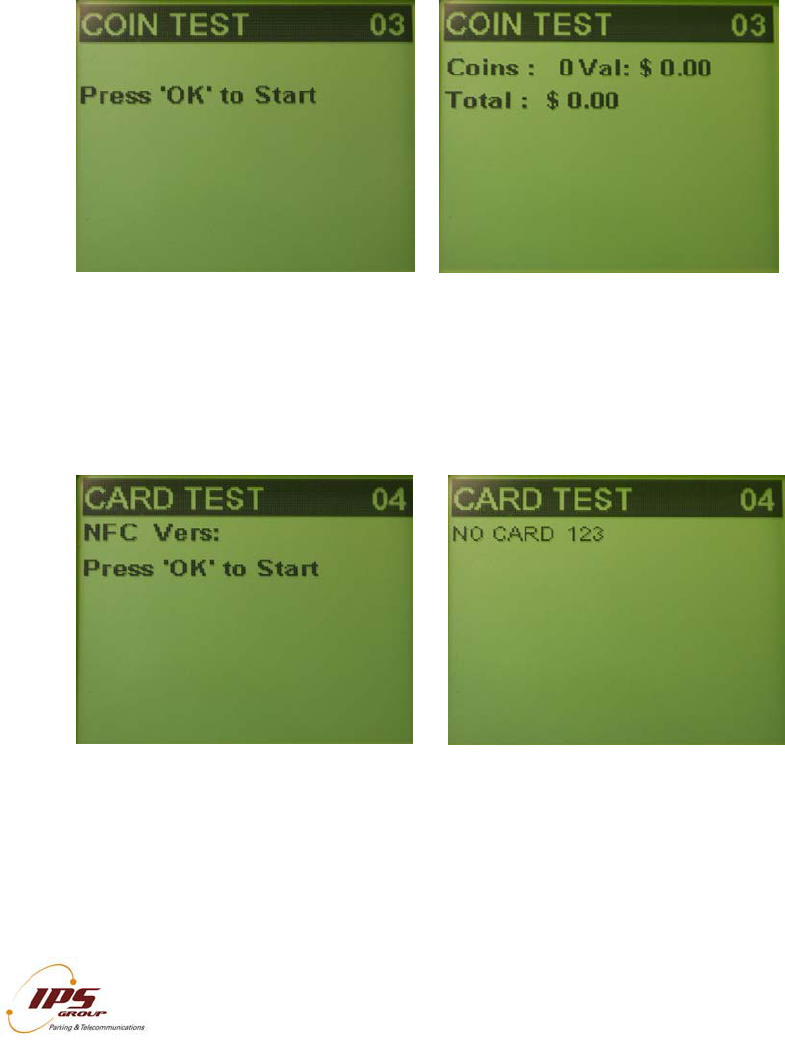
Coin Test
The coin test menu allows maintenance staff to verify that coins are validated correctly.
The two key components in coin testing are the Coins, which shows the total coin count
and Value, which is the value of the last coin inserted. When a coin is inserted, the
Coins number will increase by 1 and the value will reflect the new coin. A number with a
negative value will appear if that coin is not accepted (such as a penny). If a coin is
inserted but the Coins count does not change, this may indicate a fault with the meter or
the coin validator. Also if the value given for a particular coin is incorrect, the meter may
not be programmed correctly.
Card Test
In order to verify that a card is being read properly, it can be tested in the Card Test
menu. Once in this menu, insert and remove a card. The credit card type, number, and
expiration date should appear on the screen. This information will not be seen if the
card reader is malfunctioning or if the card is damaged.
IPS GROUP, Inc. – M5 Manual (Ver. 1.0)
All information contained herein is considered confidential
18
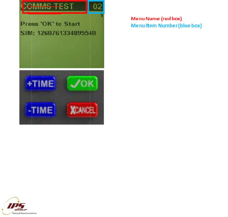
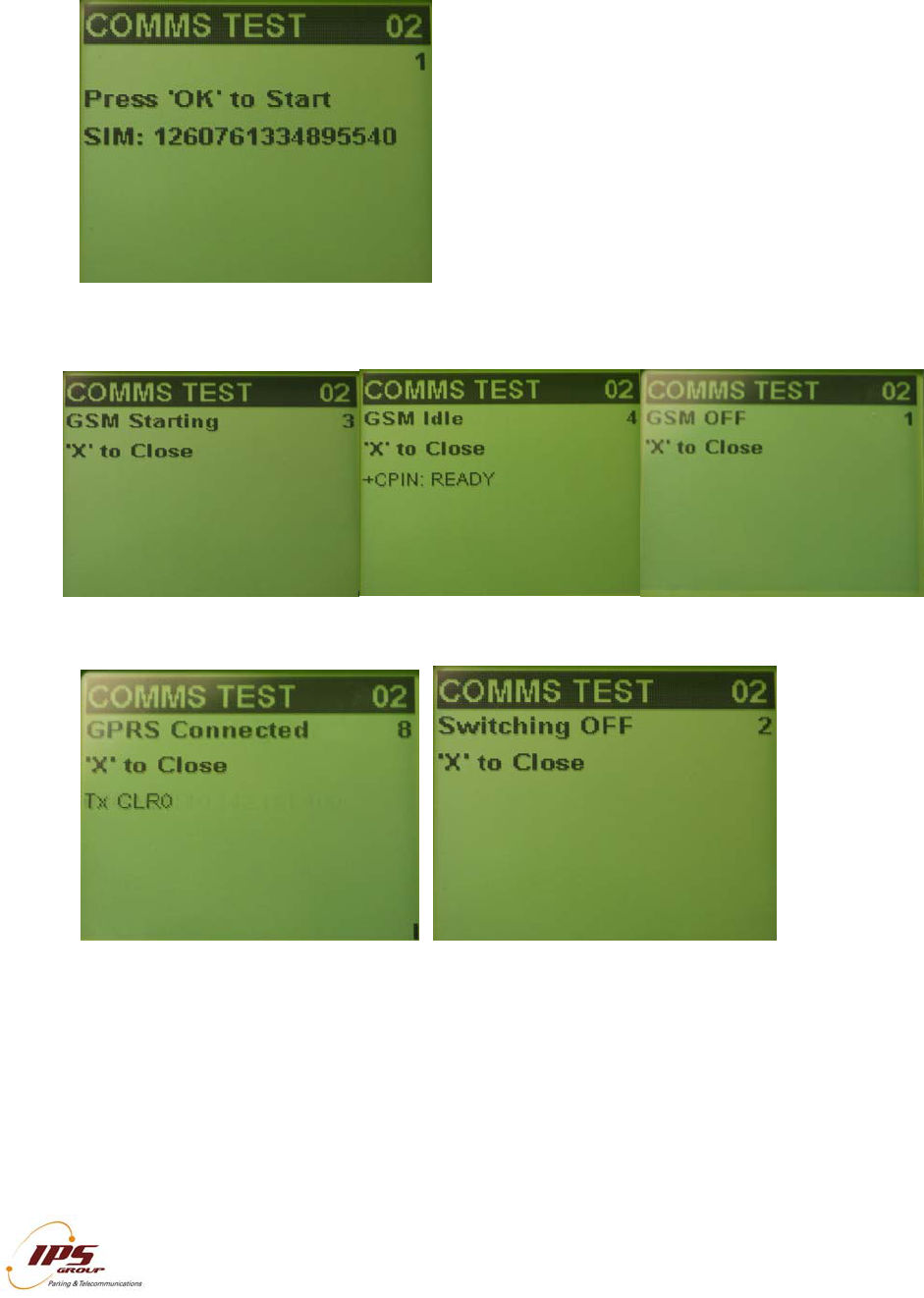
Communications Test (Comms Test)
This menu will allow you to test the meter’s
communication capabilities by forcing it to “call-
in” to the management system. The meter uses
GPRS (General Packet Radio Service)
technology to communicate over the GSM
(Global System for Mobile Communications)
network. Performing this test verifies that the
meter can successfully communicate with the
management system, updates the meter’s
internal clock, and forces the download of
available firmware and configurations. A typical
communication session will go through the
following steps:
The bottom row of each screen will display the information that is being transmitted or
received. Please refrain from pressing any buttons during the comms session so as to
not interrupt the transmission. If at any point, Error appears on the screen or Connected
is not seen, there is most likely a communication error either due to a faulty
communication module or a network error. In either case, be sure that the test is being
performed in an area with good signal strength and attempt the communication session
again. See the Troubleshooting section for ways to resolve communication problems.
IPS GROUP, Inc. – M5 Manual (Ver. 1.0)
All information contained herein is considered confidential
19
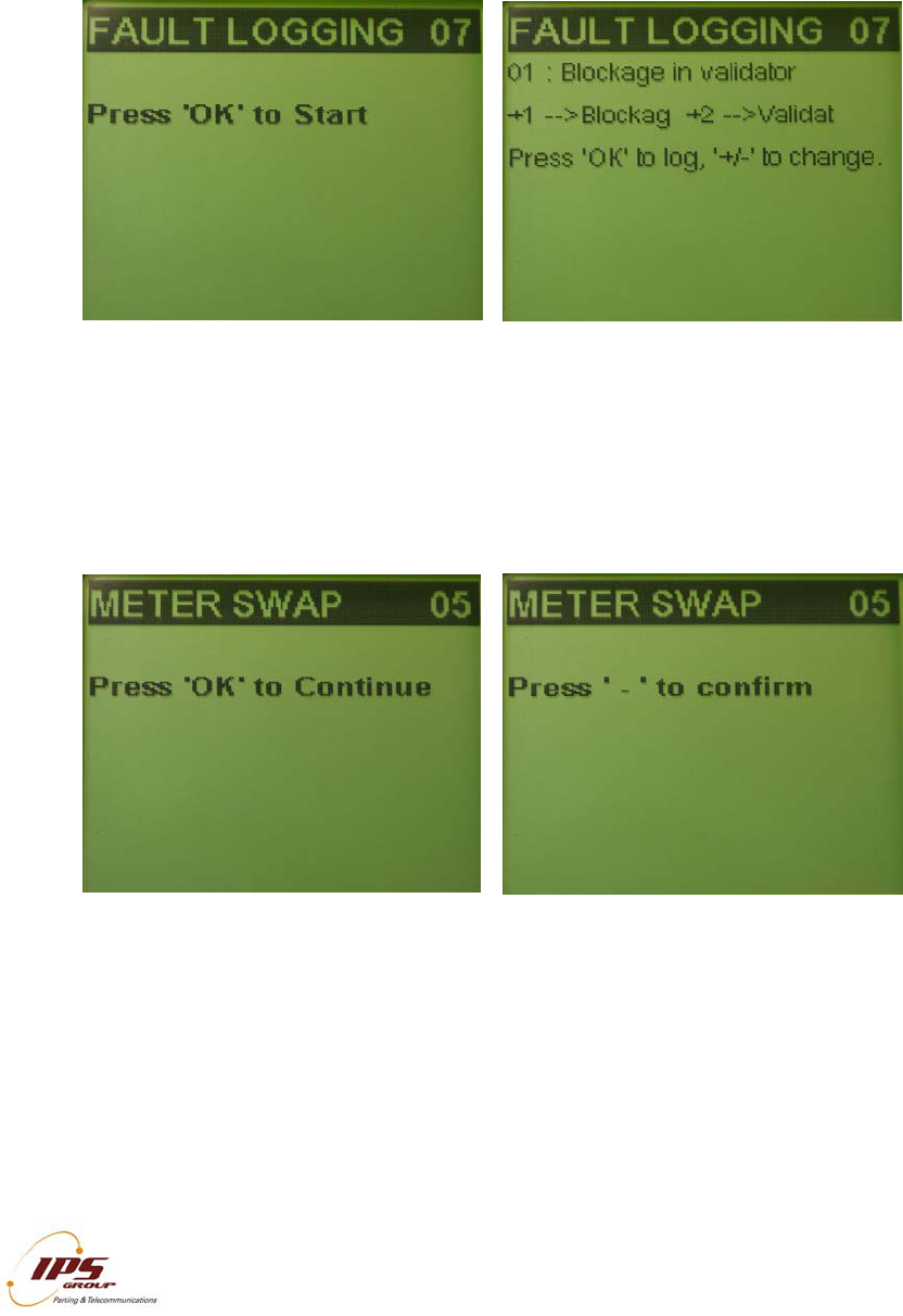
Fault Logging
In order to simplify maintenance procedures, a fault logging feature is available for use
on the meter. A fault can be logged at the meter and wirelessly transmitted to the
management system thus eliminating the need for a handheld. To use this feature,
scroll through the available options by pressing + or – and press OK to log the desired
fault. Please contact IPS to customize the fault list.
Meter Swap
When changing the meter mechanism, use the ‘Meter Swap’ option. This will start the
communication session and reset all usage information. To use this feature, press OK
once the Meter Swap menu is displayed on the screen, and press the – button to
confirm. The meter will exit out of Diagnostic Mode and complete the communication
session in the background.
IPS GROUP, Inc. – M5 Manual (Ver. 1.0)
All information contained herein is considered confidential
20
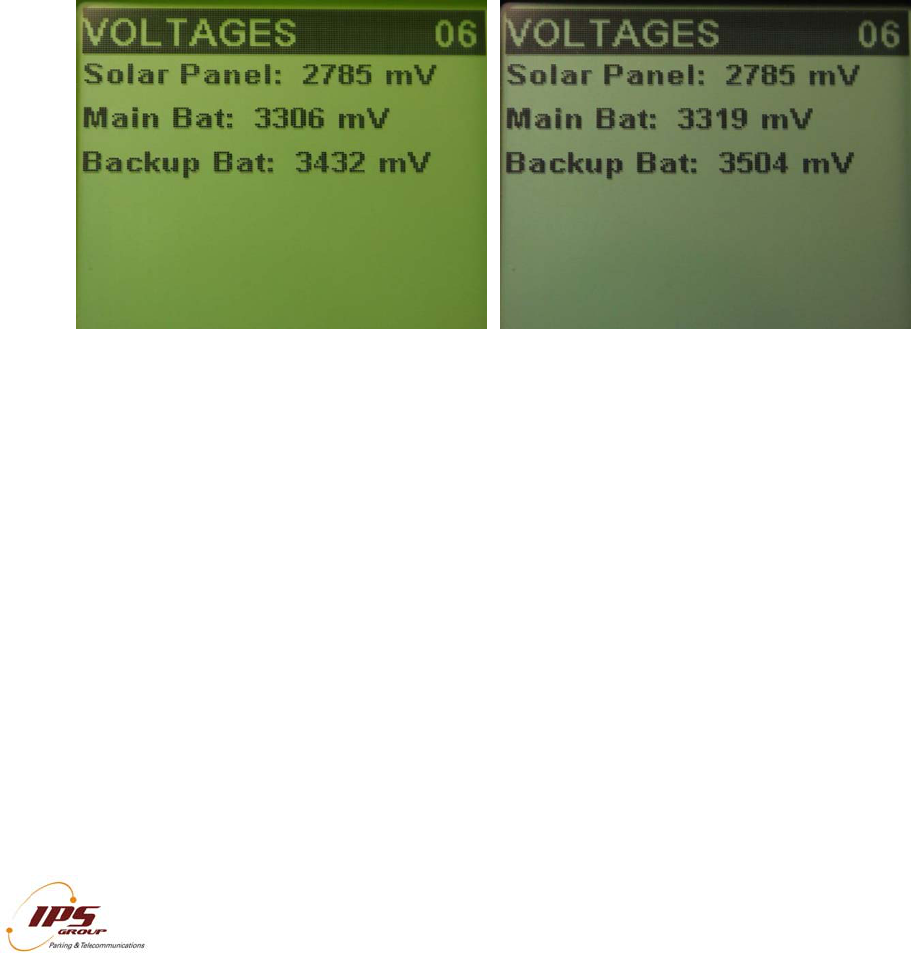
Voltages
The IPS SSPM, which is powered by battery, has a rechargeable cell and a non-
rechargeable pack. The M5 batteries are designed to use energy in an efficient manner.
The rechargeable cell is constantly recharged by the solar panel. The non-rechargeable
pack is used when the main battery voltage is too low and there is not sufficient power
coming from the solar panel. Once the power of the backup battery is exhausted, it will
no longer be functional and should be replaced. Ultracapacitors have also been included
to supplement the batteries. These are most beneficial in cold temperatures but always
store power.
The rechargeable battery is normally a lithium polymer or lithium-ion cylindrical type,
which is typically recharged from a solar panel. The non-rechargeable battery is normally
lithium-thionyl chloride (Li-SOCI2) cells designed as a backup for when the rechargeable
battery becomes discharged.
The M5 as well as the other SSPM can also use standard off-the-shelf batteries;
however, in order to have maximum capabilities, IPS recommends using our IPS battery
packs. Please note that if you would like to use off-the-shelf alkaline cells, there must be
a special battery case to hold the alkaline cells.
The Voltages menu displays information for the power sources in millivolts (mV). Solar
Panel voltage is the current voltage level of the solar panel. It may be tested for proper
operation by covering and uncovering the solar panel while ambient light is available.
The voltage levels should change from a high value (uncovered) to a low value
(covered). The battery voltages – Main and Backup – are shown separately. Please
note that the Backup battery on the display screen as well as the below chart is the non-
rechargeable battery which is plugged directly into the side of the M5. This battery has
the expectancy life of approximately five years if the meter is in optimal conditions. The
Main battery is the rechargeable cell and is directly on the Main PCB of the meter. The
values for these voltages are shown in the following table:
IPS GROUP, Inc. – M5 Manual (Ver. 1.0)
All information contained herein is considered confidential
21
Maximum Minimum Nominal
Solar Panel 5500 mV 1000 mV* 4100 mV
Main Battery 4100 mV 2800 mV 3600 mV
Backup Battery 3680 mV 2800 mV 3600 mV
* Minimum Solar Panel Voltage under indoor lighting
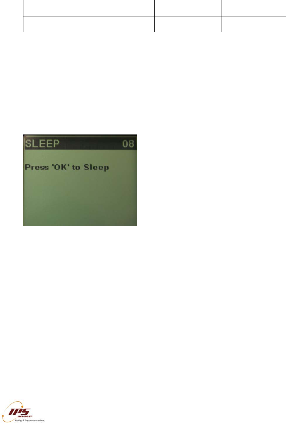
Sleep
The Sleep function allows the meter to be turned off when it is not in use, thus
conserving battery power. IPS recommends that the meter be turned off when stored or
if the meter is bagged for over 48 hours. If the meter is going to be stored for longer than
a month, then please remove the power jumper.
In order to put the meter to sleep, press OK and then press – to confirm. This can also
be accomplished by holding down the diagnostic button until a beep is heard and the
meter shuts off.

AC
C
Ther
e
Coin
and
a
regul
Met
e
This
card
IPS
r
main
t
Diag
n
Mai
n
The
m
moto
acco
u
used
Coi
n
Whe
n
in or
d
cash
b
displ
a
is us
e
trans
C
ESS C
A
e
are three
Collection
c
a
lso block t
h
ar credit ca
r
e
r Diagno
s
card is use
d
when the m
r
ecommend
t
enance act
n
ostic Mode
n
tenance (
M
m
aintenanc
e
rists credit
u
ntability, a
s
in
a
n
Collectio
n
collecting
d
er to provi
d
b
ox. Upon
a
y a confir
m
e
d, the coin
mitted to th
e
I
All infor
m
A
RDS
access car
d
c
ard. The c
a
h
e card fro
m
r
ds, having
a
s
tics Card
d
to acces
s
eter is insid
e
s
using th
e
ivity is linke
d
is entered
b
M
eter Cre
d
e
card is u
s
than feedi
n
s
the trans
a
a
simila
r
n
Card
coins from
t
d
e accurate
r
inserting th
e
m
ation mess
a
totals and
v
e
managem
e
I
PS GROUP, In
c
m
ation containe
d
d
s issued b
y
a
rds have a
m
being use
d
a
16 digit nu
the meter’
s
e
the housi
n
e
Diagnosti
c
d
to a speci
f
b
y pressing
t
d
it) Card
ed to add ti
n
g coins t
h
ctions are l
o
r
fashio
n
t
he meter, I
r
eporting of
e
card into
t
a
ge that the
v
alue are re
s
e
nt system.
c
. – M5 Manual
(
d
herein is consi
d
y
IPS: Diag
n
unique num
d
if it has b
e
mber, expir
a
s
Diagnosti
c
n
g so that r
e
c
Card to a
c
f
ic user, so
m
t
he diagnos
t
me to the
m
h
rough the
o
gged in th
e
n
as
PS recom
m
the money
c
t
he meter d
collection
h
s
et to zero,
(
Ver. 1.0)
d
ered confidenti
a
n
ostic Card
,
ber so as t
o
e
en lost or s
a
tion date,
a
c
Mode. It
i
e
moval of th
e
c
cess Diag
n
m
ething that
t
ic button b
e
m
eter. This
meter and
e
managem
a sta
n
m
ends using
c
ollected an
d
uring coin
c
h
as been co
and the col
a
l
,
Maintenan
o
be able to
t
tolen. The
a
nd card hol
d
is convenie
n
e
dome is n
o
n
ostic Mod
e
can’t be a
c
e
low the ke
y
is a quicke
also allow
s
ent system.
n
dard cr
e
the Coin C
o
d the curre
n
c
ollection, t
h
mpleted.
W
lected coin
i
2
ce Card, a
n
t
rack the us
e
cards act li
k
d
er name.
n
t to use th
o
t necessar
y
e
so that t
h
c
complished
y
pad.
r way to gi
v
s
for great
e
The card
e
dit car
d
o
llection ca
r
n
t value of t
h
h
e screen
w
W
hen the ca
r
i
nformation
2
2
n
d
e
r
k
e
is
y
.
h
e
if
v
e
e
r
is
d
.
r
d
h
e
w
ill
r
d
is
IPS GROUP, Inc. – M5 Manual (Ver. 1.0)
All information contained herein is considered confidential
23
HOW TO …
In this section, we will discuss several procedures to include: clear a coin jam, clear a
card jam, replace the battery, replace the keypad, and replace the coin slot.
Clear a Coin Jam
When a coin jam occurs, the meter maintenance staff will be notified via email or text
message. These jams typically occur due to the insertion of foreign material or insertion
of multiple coins all at once, both with the intention of jamming the meter. Otherwise, the
design of the meter is such that coin jams will happen very infrequently. If a coin
blockage does occur:
1. Remove the screw from the front of the meter
2. Pull the validator from the rear of the meter housing by pressing on the spring
loaded retention clip
3. The jam will be visible due to the design of the clear validator cover. Any thin
object (such as a screwdriver) can be used to remove the jam. In rare cases,
complete disassembly of the validator can be accomplished by removing the
screws at the corners of the validator assembly
4. With the jam cleared, insert the validator into its original position, clipping into
place
5. Replace the front validator screw

IPS GROUP, Inc. – M5 Manual (Ver. 1.0)
All information contained herein is considered confidential
24
Clear a Card Jam
Thanks to a new design feature, any coins jammed into the card reader slot are
automatically cleared with the insertion of a credit card. The coins will fall through an
opening in the card reader, thereby clearing the card path. Coins that fall into the meter
mechanism housing may be removed at a later time.
In rare cases where coins are maliciously jammed or for the removal of foreign material
in the card reader, any thin sturdy device, such as a letter opener can be used to clear
foreign objects.
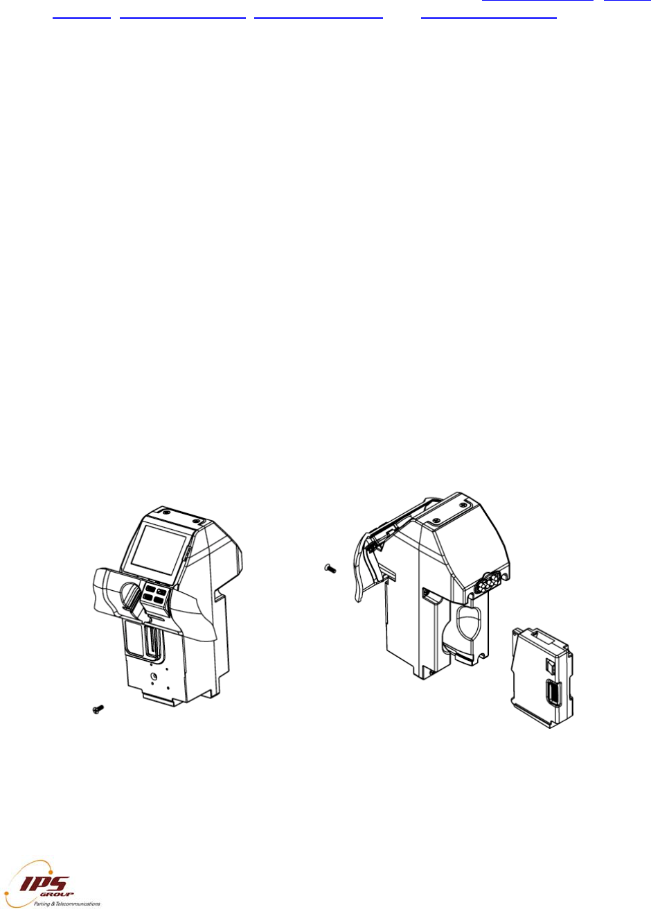
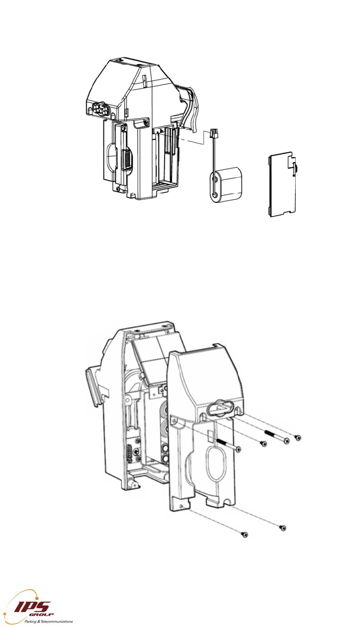
It may also be useful to remove the card reader entry slot to clear the jam. To do this,
remove the two screws on the rear of the meter as indicated in the image below:
Replace the Battery
Battery replacement is likely required approximately every two years, depending on
operating conditions. There is an additional cable required to connect the battery, which
is a three socket to a six pin battery adapter cable.
Method 1 (No tools required)
If your meter is equipped with a battery compartment cover, follow the steps below:
1. Remove the battery compartment cover
2. Disconnect and remove the old battery from the battery extension cable or the
main board connector terminal if extension cable is not present
3. Install and plug in the replacement battery
Method 2 (requires a Phillips-head screwdriver):
1. Unscrew and remove the coin validator
2. Remove the screws at the rear of the meter
3. Disconnect and remove the faulty battery from the main board connector terminal
4. Install and plug in the replacement battery
5. Insert and tighten all screws and re-insert the coin validator
Please see the diagram on the following page.
Rep
l
Met
h
Met
h
l
ace the B
a
h
od 1
h
od
2
I
All infor
m
a
ttery
I
PS GROUP, In
c
m
ation containe
d
c
. – M5 Manual
(
d
herein is consi
d
(
Ver. 1.0)
d
ered confidenti
a
a
l
2
2
5

Rep
l
The
c
repla
Valid
side
u
For
c
In or
d
confi
g
1
2
3
4
l
ace the C
o
c
oin entry s
l
ce the coi
n
ator. The
c
u
p, replace
t
c
e a Meter
d
er to force
g
uration up
d
. Enter Di
a
button of
. Scroll thr
o
. The met
e
on the k
session.
. Once th
e
meter ret
u
I
All infor
m
o
in Slot
l
ot can easi
l
n
slot, rem
o
c
oin slot sho
t
he coin vali
Update
a meter to
c
d
ate, or sim
p
a
gnostic mo
d
the keypad
o
ugh the m
e
e
r will attem
p
eypad duri
n
See Comm
s
e
meter co
m
u
rns to ope
r
I
PS GROUP, In
c
m
ation containe
d
l
y be chang
e
o
ve the Ca
r
uld easily sl
dator, and t
h
c
all in to th
e
p
ly to test c
o
d
e by press
or using the
e
nus to Co
m
p
t to commu
n
g this pro
c
s
Test for a
n
m
municatio
n
ating mode
c
. – M5 Manual
(
d
herein is consi
d
e
d in order
t
r
d Entry Sl
o
ide out. In
s
h
e card ent
r
e
managem
e
o
mmunicatio
ing the dia
g
Diagnostic
m
ms Test a
n
nicate with
t
c
ess as thi
s
n
example o
f
n
session c
o
(
Ver. 1.0)
d
ered confidenti
a
t
o accept c
o
o
t (as sho
w
s
ert the ne
w
r
y slot to co
m
e
nt system
t
o
ns:
g
nostic swit
c
Card
n
d press O
K
t
he server.
s
may inte
r
f
a typical s
e
o
mpletes,
p
a
l
o
ins of diffe
r
w
n below)
a
w
coin slot
w
m
plete the i
n
t
o get a firm
c
h located
b
K
Do not pres
s
r
rupt the c
o
e
ssion.
p
ress CAN
C
2
r
ent sizes.
T
a
nd the Co
i
w
ith the notc
h
n
stallation.
m
ware updat
e
b
elow the O
s
any butto
n
o
mmunicati
o
C
EL until t
h
2
6
T
o
in
h
-
e
,
K
n
s
o
n
h
e
IND
A.
Met
e
Part
D
1. B
a
2. B
a
3. C
o
4. N
F
5. U
N
6. C
h
7. M
o
8. V
a
9. U
N
10.
U
11.
C
12.
U
13.
M
14.
V
15.
U
16.
U
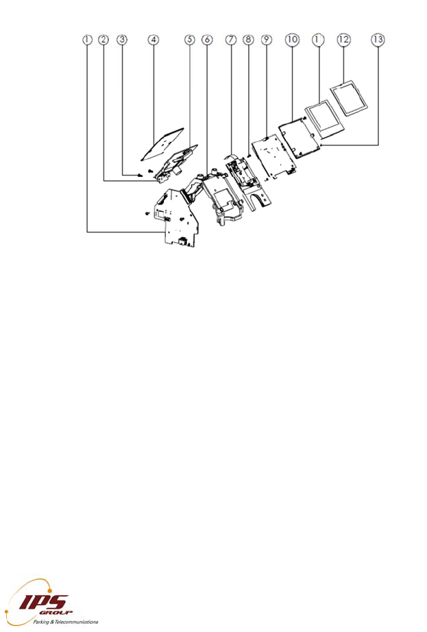
EX
Parts of
e
r Mechan
i
D
escription
s
a
ttery Cove
r
a
ttery
o
in Entry Sl
o
F
C Bezel
N
C 8-32 x 3
/
h
assis and
P
o
dule Case
R
a
lidator with
A
N
C 6-32 x 3
/
U
NC 8-32 x
2
C
ard Reader
U
NC 8-32 x
1
M
odule Cas
e
V
alidator Co
n
U
NC 4-40 x
1
U
NC 6-32 x
5
I
All infor
m
the Meter
i
sm (MK5
M
s
o
t Plate
/
8" C'Sunk
P
P
CB Assem
b
R
ea
r
A
nti-Fishing
/
16" Pan Ph
i
2
" Pan Philli
p
Entry Face
1
/2" C'Sunk
e
Front
n
nector PC
B
1
/4" Pan Ph
i
5
/16" Pan P
h
I
PS GROUP, In
c
m
ation containe
d
M
eter Mec
h
P
hillips Scre
w
b
ly with NF
C
i
llips Screw
(
p
s Screw (2
Plate / Key
p
Phillips Scr
e
B
i
llips Screw
(
h
illips Scre
w
c
. – M5 Manual
(
d
herein is consi
d
h
anism w
i
w
(2)
C
Antenna
(
2)
)
p
ad
e
w
(
4)
w
(2)
(
Ver. 1.0)
d
ered confidenti
a
i
th NF
C
)
a
l
2
2
7
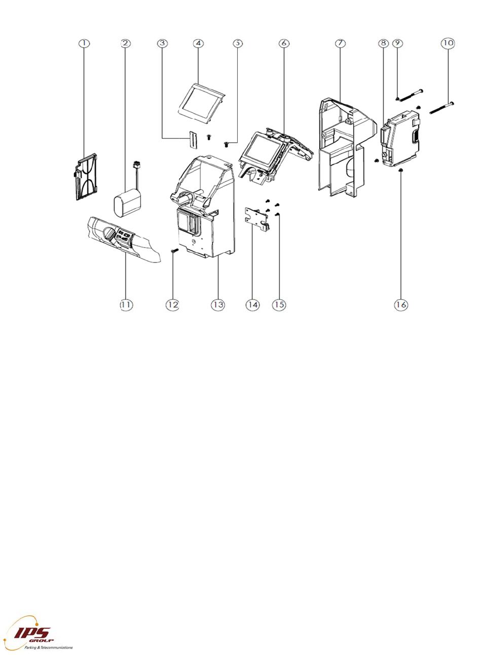
Circ
u
The I
from
parki
The
f
1
2
3
4
6
7
MK5
Part
D
1. M
a
2. E
x
3. U
N
4. S
o
5. S
o
6. C
h
7. C
a
8. U
N
9. Di
s
10. L
11. L
12.
N
13.
U
u
it Boards
/
PS meter u
s
inserted ca
r
ng operatio
n
f
unction of t
h
. Rear exp
i
. Solar as
s
LEDs
. PCBA ch
a
. Card rea
d
smart ca
r
. Display b
. Main boa
are conf
o
Dependi
n
replaced
Circuit Bo
a
D
escription
s
a
in PCB
x
piry Indicat
o
N
C 4-40 x 1
/
o
lar Panel
o
lar PCB
h
assis Fram
e
a
rd Reade
r
N
C 2-56 x 1
/
s
play PCB
CD Space
r
CD
N
FC Antenn
a
U
NC 4-40 x
1
I
All infor
m
/
Internal El
e
s
es printed
c
r
ds and coi
n
n
s staff, as
w
h
ese board
s
i
ry LEDs – f
o
s
embly – p
r
a
ssis – hold
d
er sub-ass
e
r
d applicatio
n
o
ard – inco
r
rd – house
s
o
rmally coat
n
g on the l
e
as needed
a
rds / Inter
n
s
or
/
4" Pan Phill
e
and Plate
/
4" C'Sunk
P
a
1
/4" C'Sunk
I
PS GROUP, In
c
m
ation containe
d
e
ctronics
c
ircuit boar
d
n
s to comm
u
w
ell as the I
P
s
is as follo
w
o
r enforcem
r
imarily cha
r
s all boards
e
mbly – ho
u
n
s
r
porates the
s
core proc
e
ed to prev
e
e
vel of user
by the cust
o
n
al Electro
n
ips Screw (
5
P
hillips Scre
w
u/c Phillips
S
c
. – M5 Manual
(
d
herein is consi
d
d
s and elect
r
u
nicate a v
a
P
S manage
m
w
s:
ent
r
ges batter
y
in place
u
ses the ca
r
LCD and fr
o
e
ssing and
m
e
nt fault du
e
knowledge
o
mer, or ret
n
ics
5
)
w
(4)
S
crew (3)
(
Ver. 1.0)
d
ered confidenti
a
r
onic sub-as
a
riety of inf
o
m
ent syste
m
y
pack and
r
d reader fo
r
o
nt facing e
x
m
emory fun
c
e
to exposu
r
and traini
n
urned to IP
S
a
l
semblies to
o
rmation to
t
m
.
drives rea
r
-
r
both mag
n
x
piry indicat
o
c
tions. The
c
re to moist
u
n
g, these b
o
S
for repair
/
2
process da
t
t
he motorist
s
-
facing expi
r
n
etic strip a
n
or
c
ircuit boar
d
u
re and du
s
o
ards can
b
/
replaceme
n
2
8
t
a
s
,
r
y
n
d
d
s
s
t.
b
e
n
t.

Top Co
v
MK5 To
p
Part De
s
1. Head
2. Solar
G
3. Head
4. Interf
a
5. UNC
8
v
er
(
Model
7
p
Cover (M
o
criptions
Upper Casti
G
asket
Lens
a
ce Gasket
8
-32 x 3/8"
C
IPS
G
All informatio
n
7
95)
o
del 795)
ng
C
'Sunk Philli
G
ROUP, Inc. –
M
n
contained her
e
ps Screw
M
5 Manual (Ver.
e
in is considered 1.0)
confidential
29
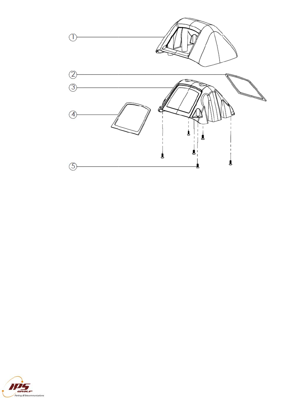
Top Co
v
Parts an
d
MK5 To
p
Part De
s
1. Head
2. Solar
G
3. Head
4. Interf
a
5. UNC
8
v
er
(
Mode
l
d
assembly
p
Cover (M
o
criptions
Upper Casti
G
asket
Lens
a
ce Gasket
8
-32 x 3/8"
C
IPS
G
All informatio
n
l
147/Mod
e
are the sa
m
o
del 147/M
o
ng
C
'Sunk Philli
G
ROUP, Inc. –
M
n
contained her
e
e
l 132)
m
e for both 1
4
o
del 132)
ps Screw (6
M
5 Manual (Ver.
e
in is considered
4
7 & 132 m
o
)
1.0)
confidential
o
dels.
30

IPS GROUP, Inc. – M5 Manual (Ver. 1.0)
All information contained herein is considered confidential
31
B. Error Status Codes
The following error codes may be displayed in the FAULTS menu when the meter is
placed in Diagnostic Mode:
Battery Low – appears when the meter’s battery drops below 3000 mV
Card Stuck – indicates an object inserted into the card reader
Coin Path Blocked – indicates an object obstructing the path of the coin or the validator
not being present
OSC Fault – appears when a coin is detected but is not validated
Time or Config error – the time on the meter is off by a more than 24 hours or the
configuration on the meter is incorrect
The following error codes may be displayed during a communication session in the
COMMS TEST menu when the meter is placed in Diagnostic Mode:
GSM Not Found – meter cannot communicate with the GSM radio
CME ERROR 10 – SIM not inserted
CME ERROR 107 – GPRS service not allowed
CME ERROR 553 – context already activated
CME ERROR 555 – activation failed
CME ERROR 557 – cannot setup socket
CME ERROR 559 – time out in opening socket

IPS GROUP, Inc. – M5 Manual (Ver. 1.0)
All information contained herein is considered confidential
32
C. Troubleshooting
Power
Problem: The meter’s display is blank and the LEDs are not flashing.
Solution: Be sure to turn the meter on. This can be done by inserting any card into the
meter. Insert it completely up the card slot and wait for a beep.
If this fails, be sure the battery is plugged in. Also, verify that the card reader
connector is attached to the solar panel and that the solar panel is fully
connected to the main board.
Problem: The meter’s display is blank but the LEDs are on continuously.
Solution: Replace the battery.
Problem: In the Voltage Menu item of the Diagnostic Menu, the Solar Panel voltage is
reported as being extremely low (i.e. under 500 mV).
Solution: Verify that the Solar Panel is properly connected to the Main board and there
is nothing obstructing the Solar Panel.
Problem: The display is blank, but the lights are flashing.
Solution: Press the diagnostics button. If text appears on the screen, press Cancel. If
the screen is still blank, inspect the LCD ribbon cable for damage. Verify that
the Display Board is fully connected to the Main board.
Coin Issues
Problem: The meter reads Cards Only/No Coins. In Diagnostic Mode, the meter
shows “Coin Path Blocked”.
Solution: Check the validator for any obstructions. If the problem persists, check that
the validator is properly plugged in and that the connector cable is not loose.
Also check that the validator connector board is intact.
Problem: The meter reads Cards Only/No Coins. In Diagnostic Mode, the meter shows
“OSC Fault”.
Solution: Check the validator for any obstructions. Try swapping the validator with
another one as one of the coils of the existing validator may be damaged.
Communication Issues
Problem: During communications, the meter displays “GSM NOT FOUND”.
Solution: Make sure that the Solar Panel Board is properly attached to the Main Board.
Problem: During communications, the meter displays “NO SIM”.
Solution: Verify that the SIM card is fully inserted into the SIM. Remove and replace
the SIM card and force the meter to contact the management system.

IPS GROUP, Inc. – M5 Manual (Ver. 1.0)
All information contained herein is considered confidential
33
Problem: During communications, the meter displays “CSQ 99,99” or “CSQ 0,0” and
never displays “Connected”.
Solution: The antenna is not properly attached or the antenna cable is broken. Contact
IPS about replacing the antenna. The meter may also be in a location with
poor signal strength.
Problem: During communications, the meter displays “CME ERROR: XXX”.
Solution: This is typically the result of a network issue. Contact IPS to verify that the
system is operational.
Problem: The meter has the wrong configuration.
Solution: When using an RFID tag, be sure that upon entering Diagnostic Mode the
meter has a value for RFID. If all zeros are displayed, check the connection
of the cable from the RFID Tag Reader board to the Main Board. You can
also use another meter to read the tag. If the new meter shows a value for
the RFID number, then the fault is with the meter. In case both meters fail to
read the tag, try another tag. Verify that the meter is properly assigned in the
management system. Be sure communications are working by going through
the Comms Test in the Diagnostic Menu.
D. Cleaning and General Maintenance
For general cleaning purposes, IPS recommends the following procedures. Based on
environmental and use conditions, the frequency of these maintenance techniques
should be judged by the local maintenance staff and be increased or decreased
appropriately.
Meters surfaces should be kept clean with mild soap and water
Compressed air may be used to keep the card reader and coin acceptor clear of
debris
The card reader heads should be cleaned with a cleaning card every 1-2 months
to ensure optimum performance of the card reader. Cleaning cards may be
purchased from IPS
The coin validator should be visually inspected for any damage or debris every 6
months.