IRay Technology 02110113 Wireless Digital Flat Panel Detector User Manual 2
iRay Technology (Shanghai) Ltd. Wireless Digital Flat Panel Detector Users Manual 2
UserManual.wiki
>
IRay Technology
>
02110113 User Manual
>
Users Manual-2
Contents
1.
User manual
2.
Users Manual-1
3.
Users Manual-2
Users Manual-2
Navigation menu
Upload a User Manual
Namespaces
Wiki Guide
HTML
PDF
Info
Views
User Manual
Discussion / Help
Navigation

![iRay Technology (Shanghai) Ltd. Doc N0. 037‐201‐02 Version A1 Mars1717VUser’sManual Date 2015.11.06 Page 122/141Page 122 Mars1717V is used exceeds the applicable RF compliance level above, Mars1717V should be observed to verify normal operation. If abnormal performance is observed, additional measures may be necessary, such as re-orienting or relocating Mars1717V. b. Over the frequency range 150 kHz to 80 MHz, field strengths should be less than [V1] V/m. Recommended separation distances between portable or mobile RF communications equipment and Mars1717V Mars1717V is intended for use in an electromagnetic environment in which radiated RF disturbances are controlled. The customer or user of Mars1717V can help prevent electromagnetic interference by maintaining a minimum distance between portable or mobile RF communications equipment (transmitters) and Mars1717V as recommended below, according to the maximum output power of the communications equipment. Rated maximum output power of transmitter /W Separation distance according to frequency of transmitter /m 150kHz~80 MHz d = 1.2 p 80 MHz~800 MHz d = 1.2 p 800 MHz ~2.5GHz d = 2.3 p 0.01 0.12 0.12 0.23 0.1 0.38 0.38 0.73 1 1.2 1.2 2.3 10 3.8 3.8 7.3 100 12 12 23 For transmitters rated at a maximum output power not listed above, the recommended separation distance d inmeters (m) can be estimated using the equation applicable to the frequency of the transmitter, where P is the maximum output power rating of the transmitter in watts (W) according to the transmitter manufacturer. NOTE 1 At 80 MHz and 800 MHz, the separation distance for the higher frequency range applies. NOTE 2 These guidelines may not apply in all situations. Electromagnetic propagation is affected by absorption and reflection from structures, objects and people. Cables information belowis provided for EMC reference.](https://usermanual.wiki/IRay-Technology/02110113.Users-Manual-2/User-Guide-2816527-Page-51.png)
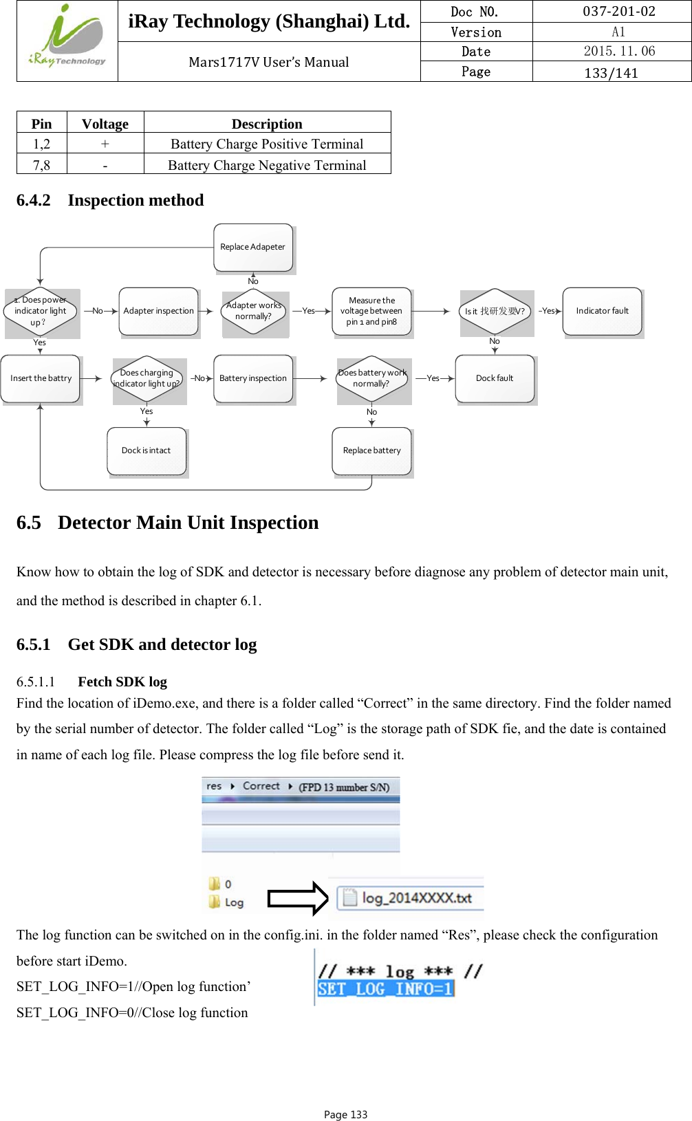
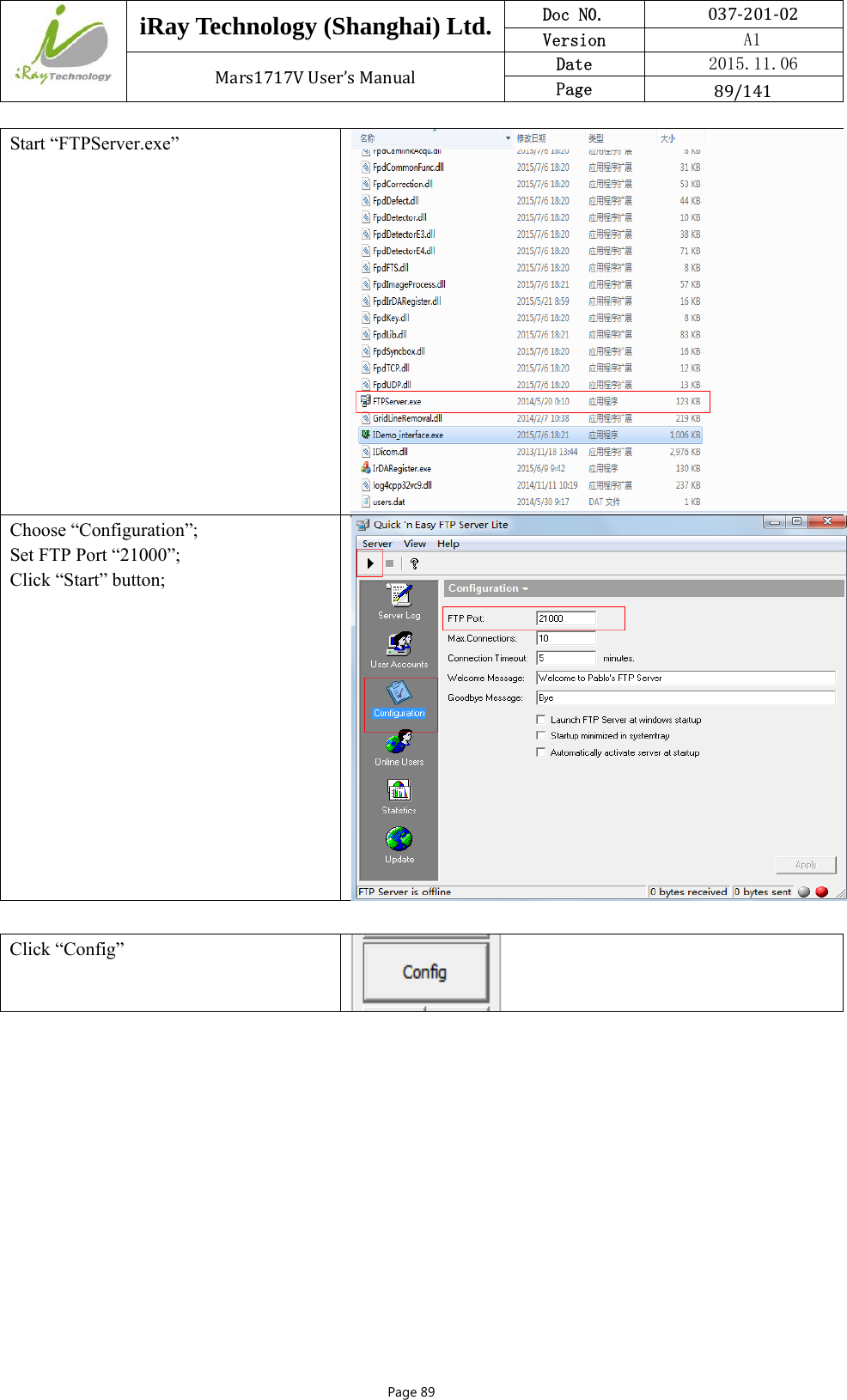
![iRay Technology (Shanghai) Ltd. Doc N0. 037‐201‐02 Version A1 Mars1717VUser’sManual Date 2015.11.06 Page 134/141Page 134 6.5.1.2 Detector log Find FTP Server.exe and open the FTP Server, attention that the FTP port number should be set as same as the config.ini of iDemo. Click button to start FTP server after finish setting the FTP port number. Find the “L” button in the following diagram in the configuration GUI of iDemo, click “L” button and the FTP will upload the “Log” in the storage path “upload\[FPD 13 number S/N]\logs” which is at the same location of iDemo.exe.](https://usermanual.wiki/IRay-Technology/02110113.Users-Manual-2/User-Guide-2816527-Page-63.png)
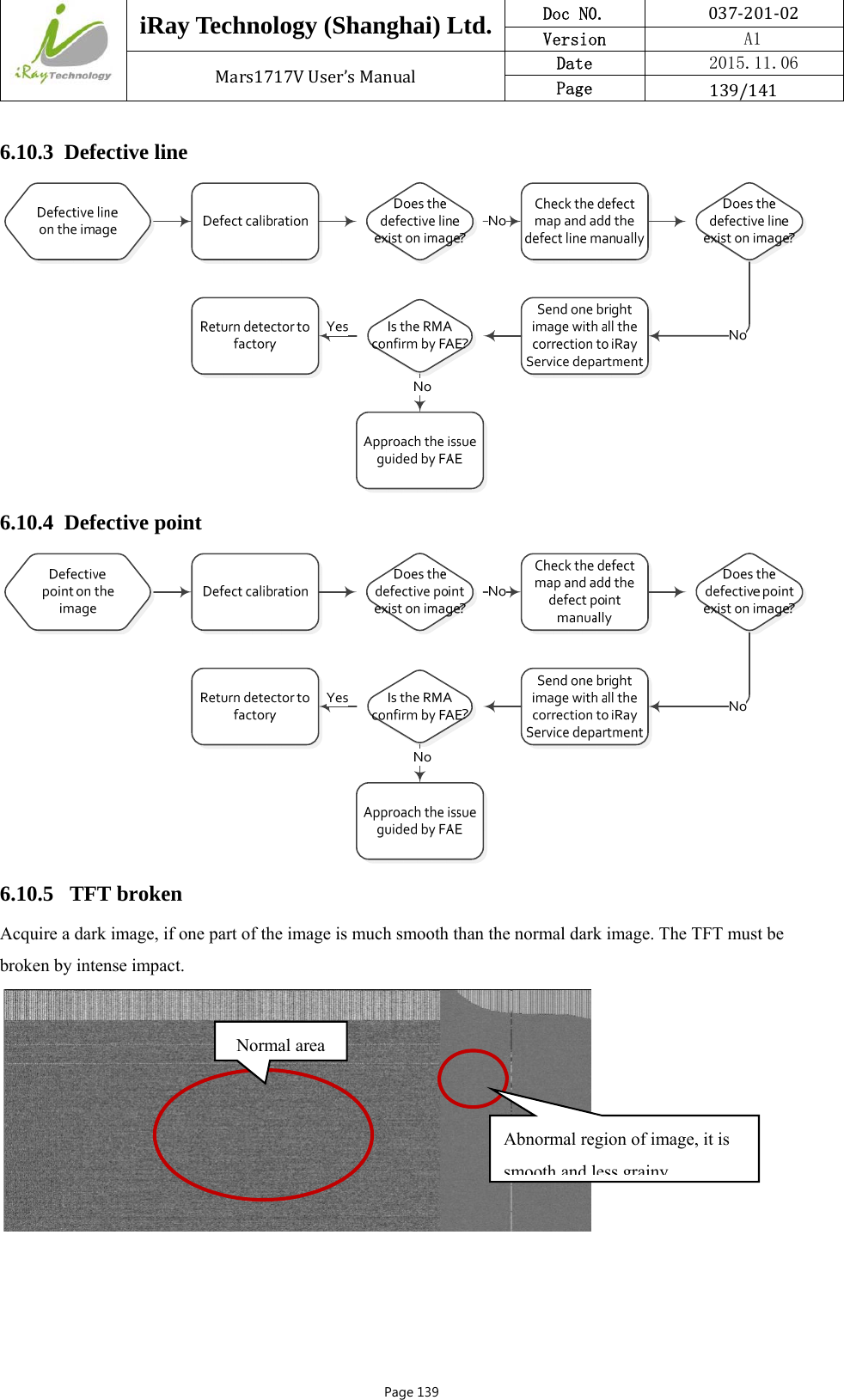
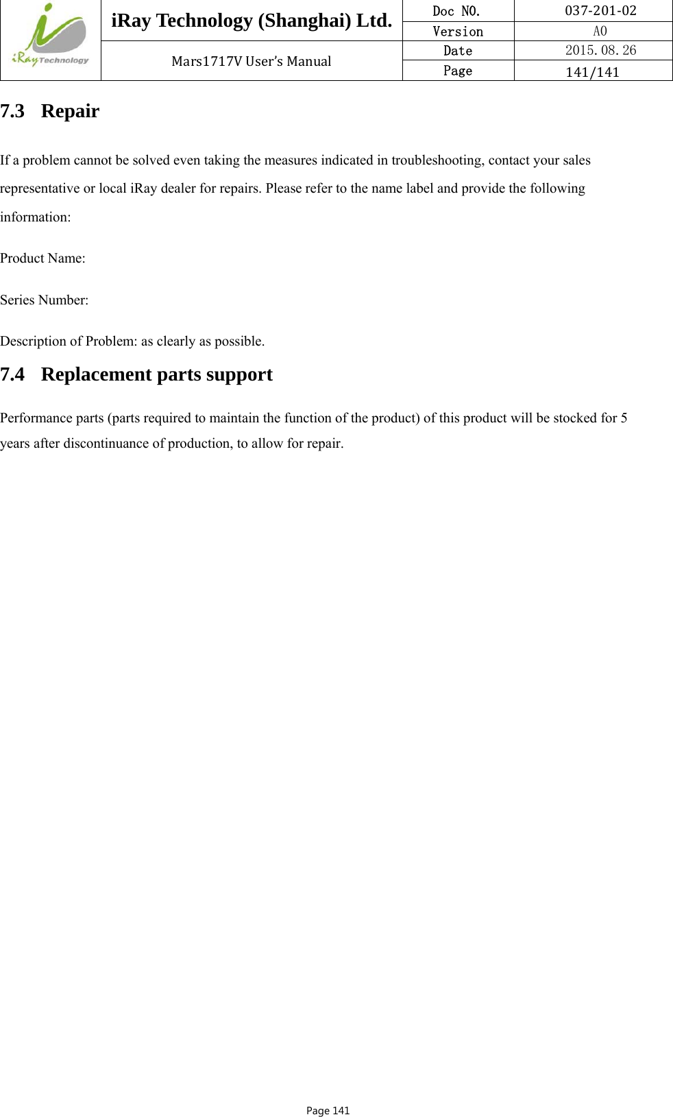
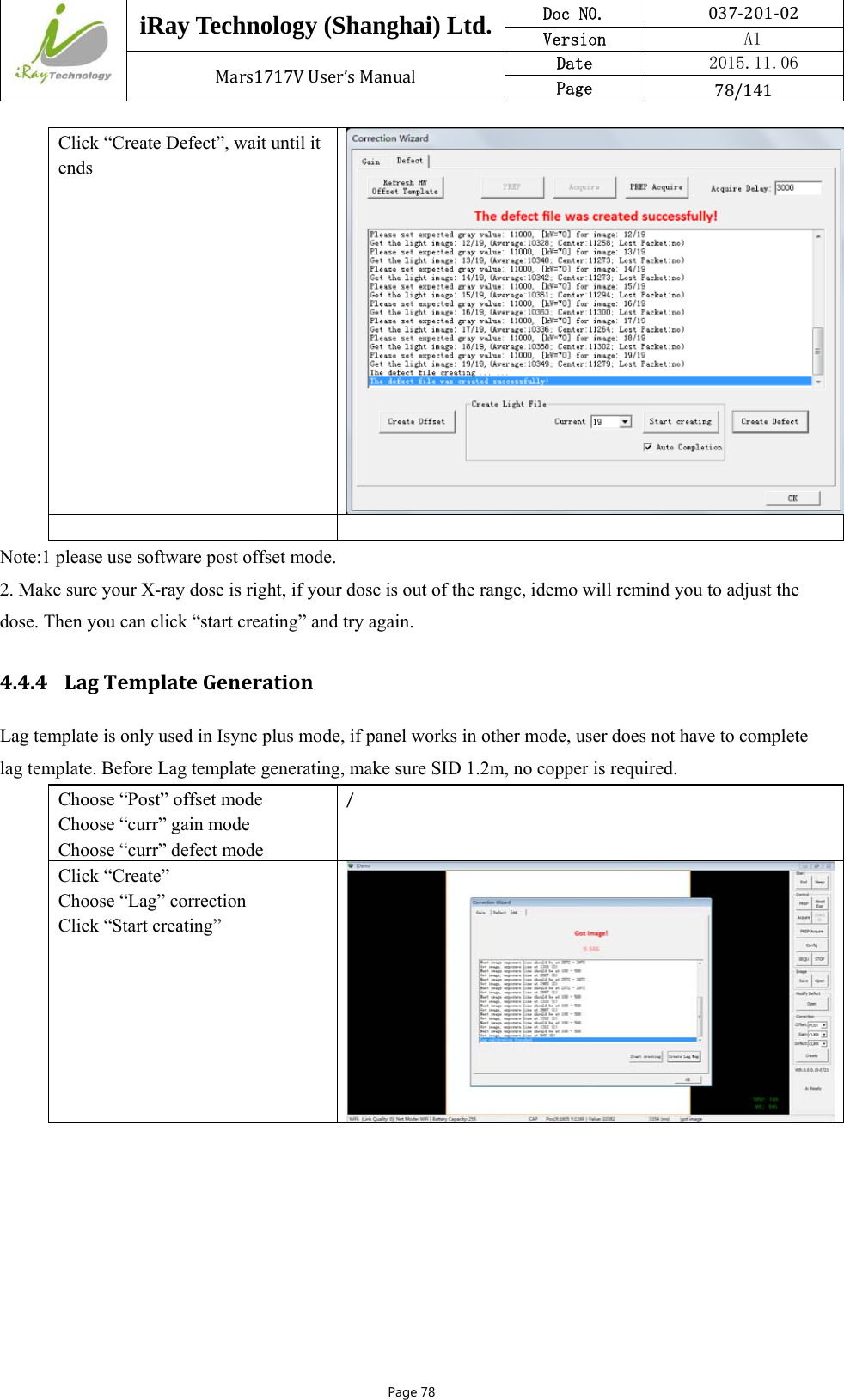
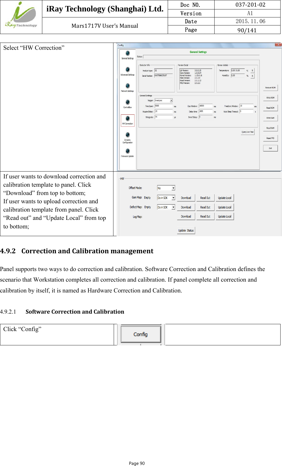
![iRay Technology (Shanghai) Ltd. Doc N0. 037‐201‐02 Version A1 Mars1717VUser’sManual Date 2015.11.06 Page 137/141Page 137 6.9 No Image Acquire after Exposure 6.10 Image Inspection All the correction files are in the storage path “res\Correct\ [FPD series number] \0” Calibration type File format Remark Offset *.off iRay mostly use post offset, the offset is done during the image acquisition process. So the offset file is not effective in the correction file storage path. Gain *.gn The gain file can be select or deselect through iDemo Defect *.dft The gain file can be select or deselect through iDemo Lag *.lag The Most gain is effective while it’s in the correction file storage path. Rename it or move it to other directory can make it invalid. The following is the image Image type Description Original dark image Acquire by click “Prep Acquire” button without exposure and offset correction Dark image Acquire by click “Prep Acquire” button without exposure and the offset calibration should be added at least. Original bright image Acquire the image under exposure condition and without any correction. Bright image with offset Acquire the image under exposure condition and add offset correction only. 6.10.1 Artifact on bright image 6.10.2 Horizontal Line on bright image Adjust the WW to 30 and WL to 100 through iDemo for checking the horizontal line of dark image. Normally the dark image with horizontal line is shown as the figure 1.](https://usermanual.wiki/IRay-Technology/02110113.Users-Manual-2/User-Guide-2816527-Page-66.png)