IRay Technology 02110113 Wireless Digital Flat Panel Detector User Manual 2
iRay Technology (Shanghai) Ltd. Wireless Digital Flat Panel Detector Users Manual 2
Contents
- 1. User manual
- 2. Users Manual-1
- 3. Users Manual-2
Users Manual-2
iRay Technology (Shanghai) Ltd. Doc N0. 037‐201‐02
Version A1
Mars1717VUser’sManual Date 2015.11.06
Page 72/141
Page 72
3. The rule of Multi-Share control is based on IP address. The second terminal with different IP address is
not allowed to operate panel after the first one connected. If there is no command transmission between panel
and Workstation over 5 minutes, panel releases access authority.
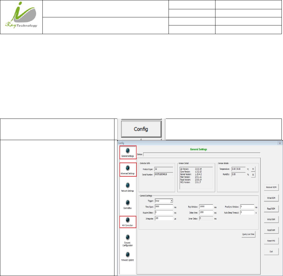
4.3 PanelConfiguration
Click “Config”
Set parameters
Note: 1. If panel works in Isync Plus mode, it is not allowed to change any parameters and write into ROM
or RAM. User is required to switch to software mode, change parameters and then switch to Isync Plus
mode. On the other hand, we do not recommend user to switch working mode too often.
4.4 CorrectionandCalibrationTemplateGeneration
Iray recommends performing correction and calibration after installation or any major change on the system
settings and hardware configuration. On the other hand, it is also recommended to do the correction and
calibration in each 6 months.
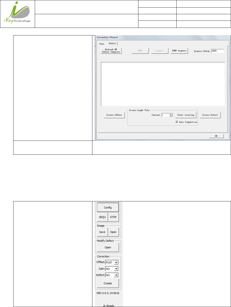
4.4.1 Pre‐offsetTemplateGeneration
If panel is configured to do Pre-offset correction, Pre-offset Template is necessary. See below
iRay Technology (Shanghai) Ltd. Doc N0. 037‐201‐02
Version A1
Mars1717VUser’sManual Date 2015.11.06
Page 73/141
Page 73
Click “ Create”, Choose “Defect”
Click “Create Offset”, wait until
image acquisition ends
/
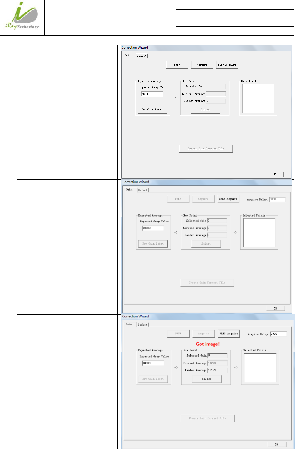
4.4.2 GainCalibrationTemplateGeneration
Before Gain template generating, make sure SID1.2m, no copper is required,
Choose “Post” offset mode1
iRay Technology (Shanghai) Ltd. Doc N0. 037‐201‐02
Version A1
Mars1717VUser’sManual Date 2015.11.06
Page 74/141
Page 74
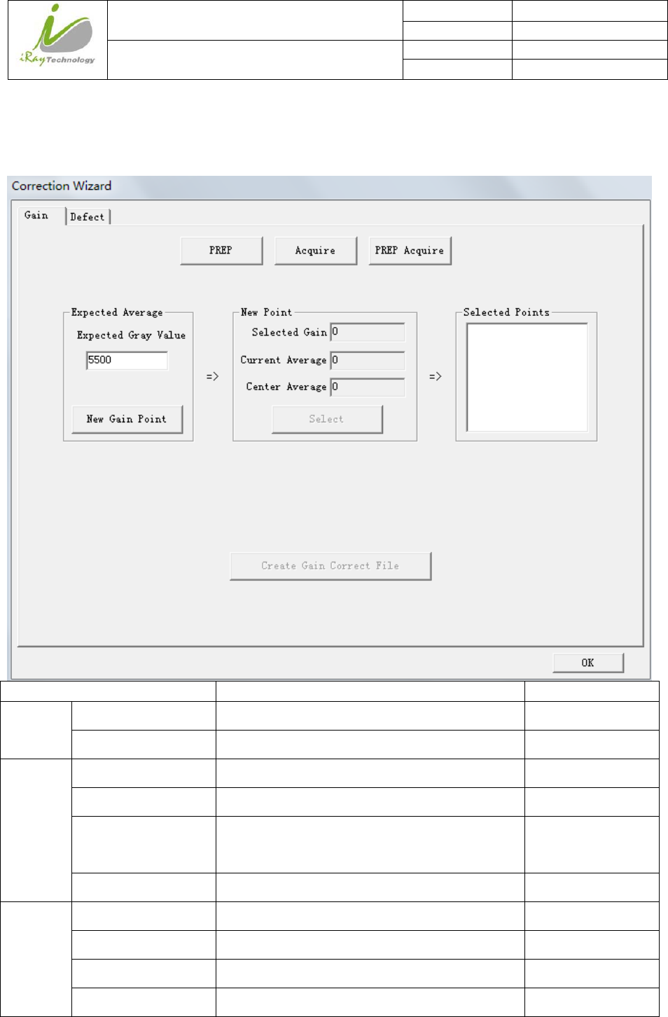
Click “ Create”, Choose “Gain”
Set “Expected Gray Value” 10000;
Click “New Gain Point”;
Set “Acquire Delay” 3000;
If panel is in software mode, click
“Prep” ,shoot X-ray, click
“Acquire”;
If panel is in Inner mode, click
“Prep”, shoot X-ray;
If panel is in Isync Plus mode,
click “Prep Acquire”, wait for
ready, shoot X-ray. Time window
can be set by “Acquire Delay”;
Wait for Post-offset image
uploaded, there will be value
shown in “current average” box,
change X-ray dose to make sure
“current average” in the range of
10000±100, If yes, Click “Select”
iRay Technology (Shanghai) Ltd. Doc N0. 037‐201‐02
Version A1
Mars1717VUser’sManual Date 2015.11.06
Page 75/141
Page 75
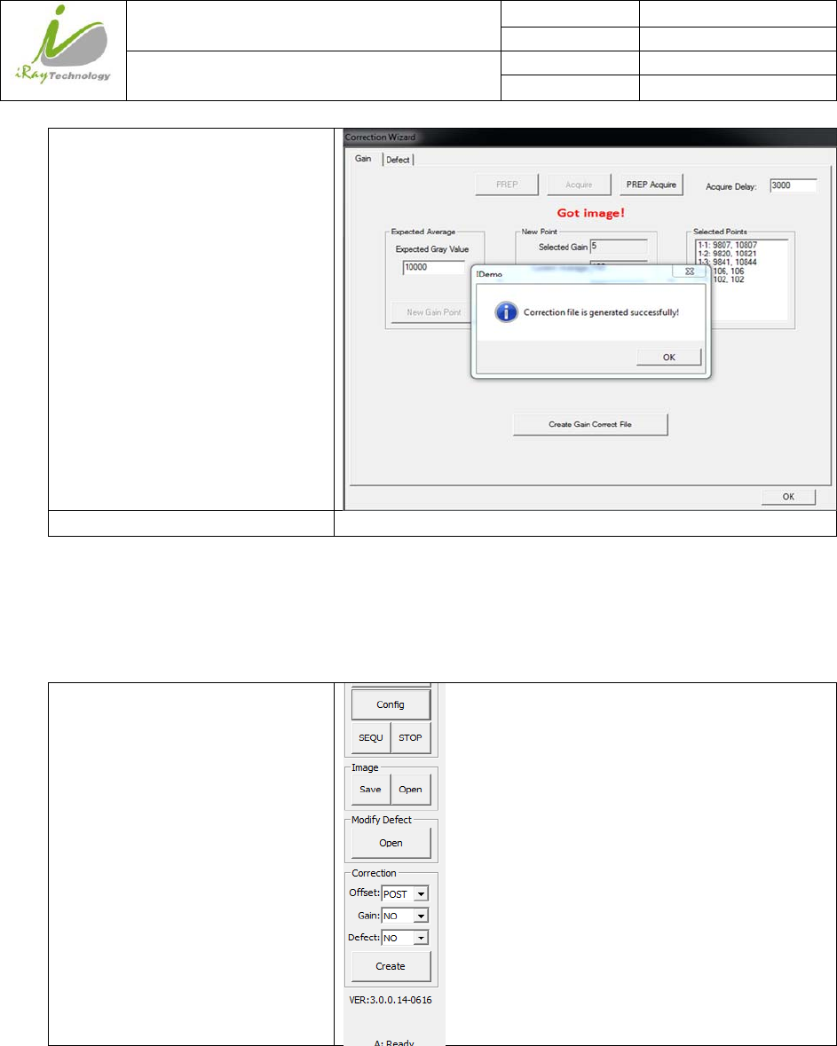
Repeat the same operation for 4
times, “Create Gain Correct file”
button can be available, Click
“Create Gain Correct file”
Click “OK” /
Note:1 please use software post offset correction.
4.4.3 DefectCorrectionTemplateGeneration
Before Defect template generating, make sure SID1.2m, no copper is required,
Choose “Post” offset mode1
iRay Technology (Shanghai) Ltd. Doc N0. 037‐201‐02
Version A1
Mars1717VUser’sManual Date 2015.11.06
Page 76/141
Page 76
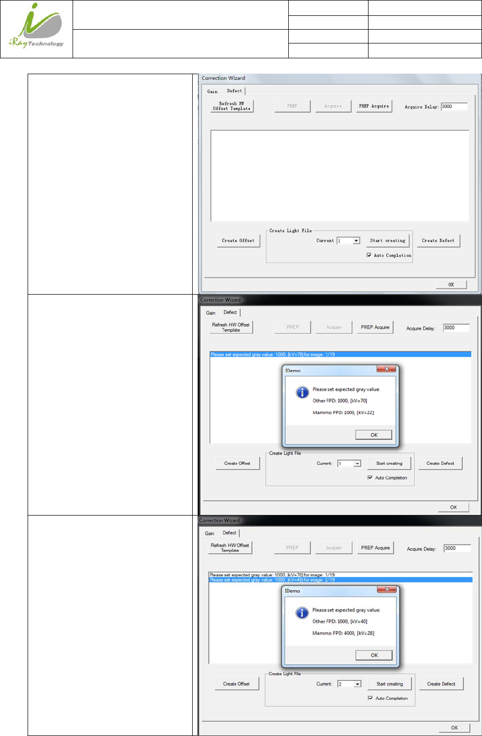
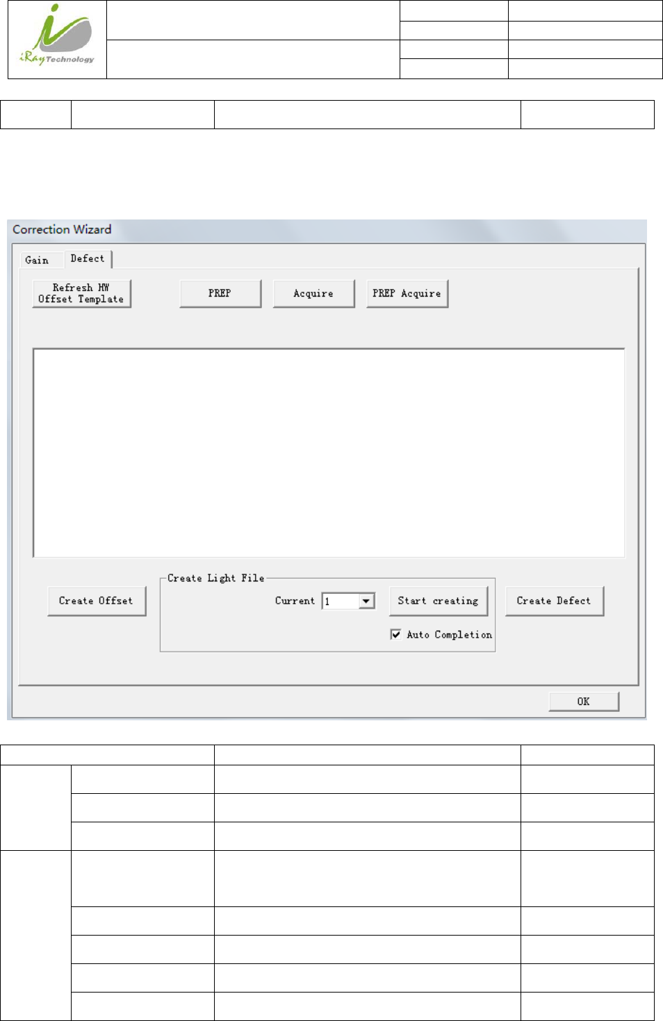
Click “ Create”, Choose “Defect”
Click “start creating”, message box
will show you the first image value
for defect correction2;
If panel is in software mode, click
“Prep” ,shoot X-ray, click
“Acquire”;
If panel is in Inner mode, click
“Prep”, shoot X-ray;
If panel is in Isync Plus mode,
click “Prep Aquire”, wait for ready,
shoot X-ray. Time window can be
set by “Acquire Delay”;
Click “start creating” to start the
second X-ray shoot
iRay Technology (Shanghai) Ltd. Doc N0. 037‐201‐02
Version A1
Mars1717VUser’sManual Date 2015.11.06
Page 77/141
Page 77
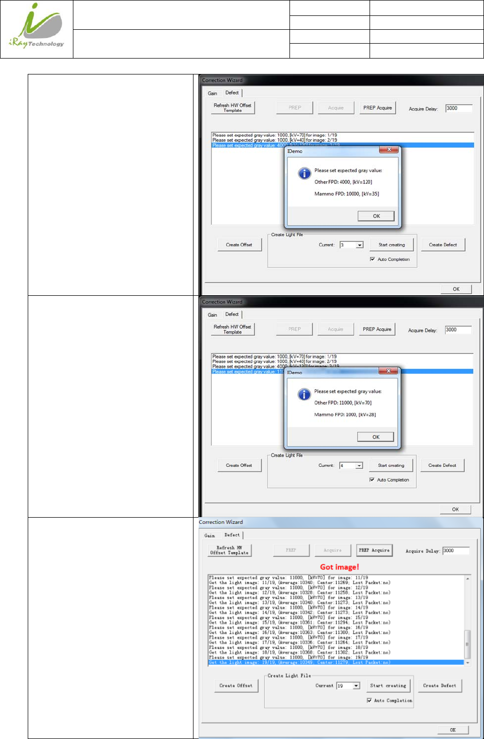
Click “start creating” to start the
third X-ray shoot
Click “start creating” to start the
fourth X-ray shoot
After the fourth X-ray shoot, you
do not need to change the X-ray
dose, just repeat operation of “start
creating” and image acquisition
until it comes to the 19th images.
iRay Technology (Shanghai) Ltd. Doc N0. 037‐201‐02
Version A1
Mars1717VUser’sManual Date 2015.11.06
Page 78/141
Page 78
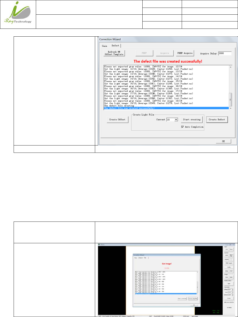
Click “Create Defect”, wait until it
ends
Note:1 please use software post offset mode.
2. Make sure your X-ray dose is right, if your dose is out of the range, idemo will remind you to adjust the
dose. Then you can click “start creating” and try again.
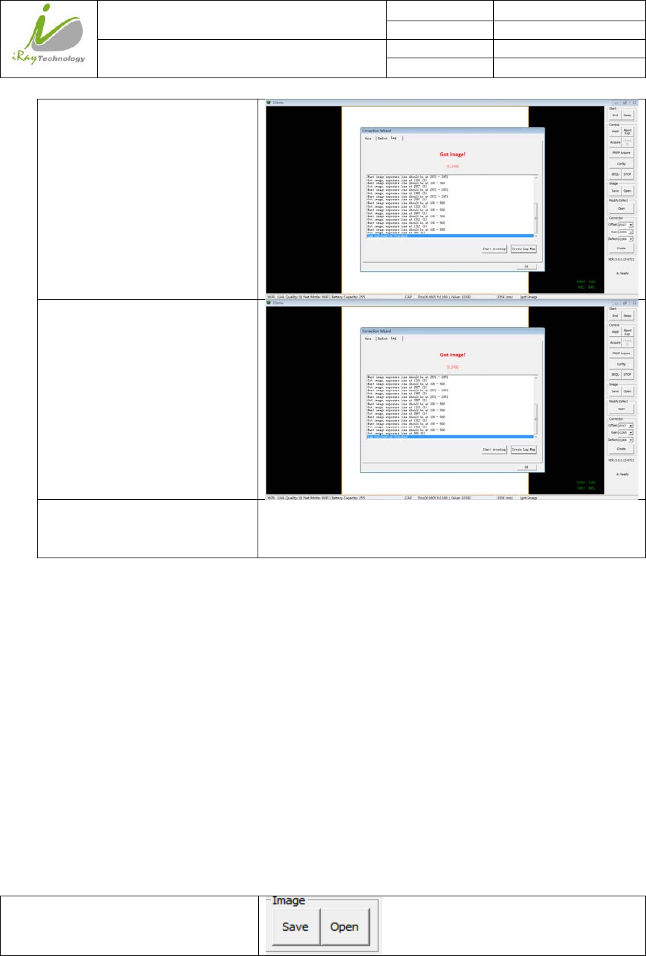
4.4.4 LagTemplateGeneration
Lag template is only used in Isync plus mode, if panel works in other mode, user does not have to complete
lag template. Before Lag template generating, make sure SID 1.2m, no copper is required.
Choose “Post” offset mode
Choose “curr” gain mode
Choose “curr” defect mode
/
Click “Create”
Choose “Lag” correction
Click “Start creating”
iRay Technology (Shanghai) Ltd. Doc N0. 037‐201‐02
Version A1
Mars1717VUser’sManual Date 2015.11.06
Page 79/141
Page 79
Change X-ray dose to make sure
average gray value in the range of
10000±100, Shoot X-ray, Post-
offset image is shown on screen,
make sure exposure line between
100 and 500;
Shoot X-ray, another Post-offset
image is shown on screen, make
sure exposure line between 2572
and 2972;
Image acquisition finished;
Click “Create Lag Map”;
Display “Lag calibration finished”,
correction finished, close
correction window
/
4.5 ImageAcquisitionContinually
Image Acquisition continually can be used only in software mode and inner mode, it is not supported in
Isync Plus mode. The operation is designed for panel testing, not for customer using.
“SEQU” is the command to start image acquisition and “STOP” is the opposite. If user wants to change
frequency of image acquisition, change parameters in “Config-General Setting-Time Span”.
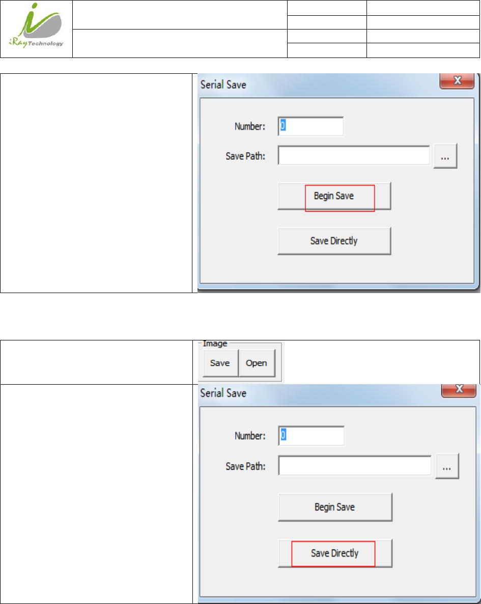
4.6 Imagesave
“SAVE” provides two features of image saving for user. The first is saving multiple images, the second is
saving single image.
4.6.1 Multipleimages
Click “Save”
iRay Technology (Shanghai) Ltd. Doc N0. 037‐201‐02
Version A1
Mars1717VUser’sManual Date 2015.11.06
Page 80/141
Page 80
Set the number of images in blank;
Choose the saving path;
Click “Begin Save”;
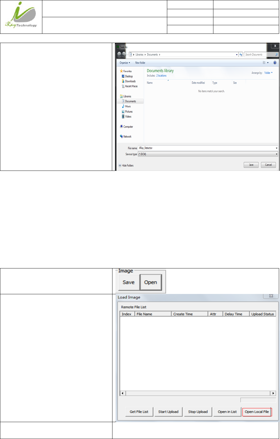
4.6.2 Singleimage
Click “Save”
Click “Save Directly”
iRay Technology (Shanghai) Ltd. Doc N0. 037‐201‐02
Version A1
Mars1717VUser’sManual Date 2015.11.06
Page 81/141
Page 81
Choose the saving path;
Click “save”;
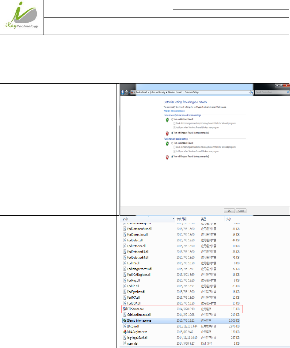
4.7 ImageCheckandupload
“OPEN” provides three feature for image check and uploading. Local Image Check, Panel Image Upload and
Panel Image Check. Local Image Check defines function to check image saved in Workstation. Panel Image
Upload defines function to upload images stored in panel. Panel Image Check defines function to check
images stored in panel.
4.7.1 LocalImageCheck
Click “Open”
Click “Open Local File”
Choose images stored in Workstation,
images would be shown on screen
/
iRay Technology (Shanghai) Ltd. Doc N0. 037‐201‐02
Version A1
Mars1717VUser’sManual Date 2015.11.06
Page 82/141
Page 82
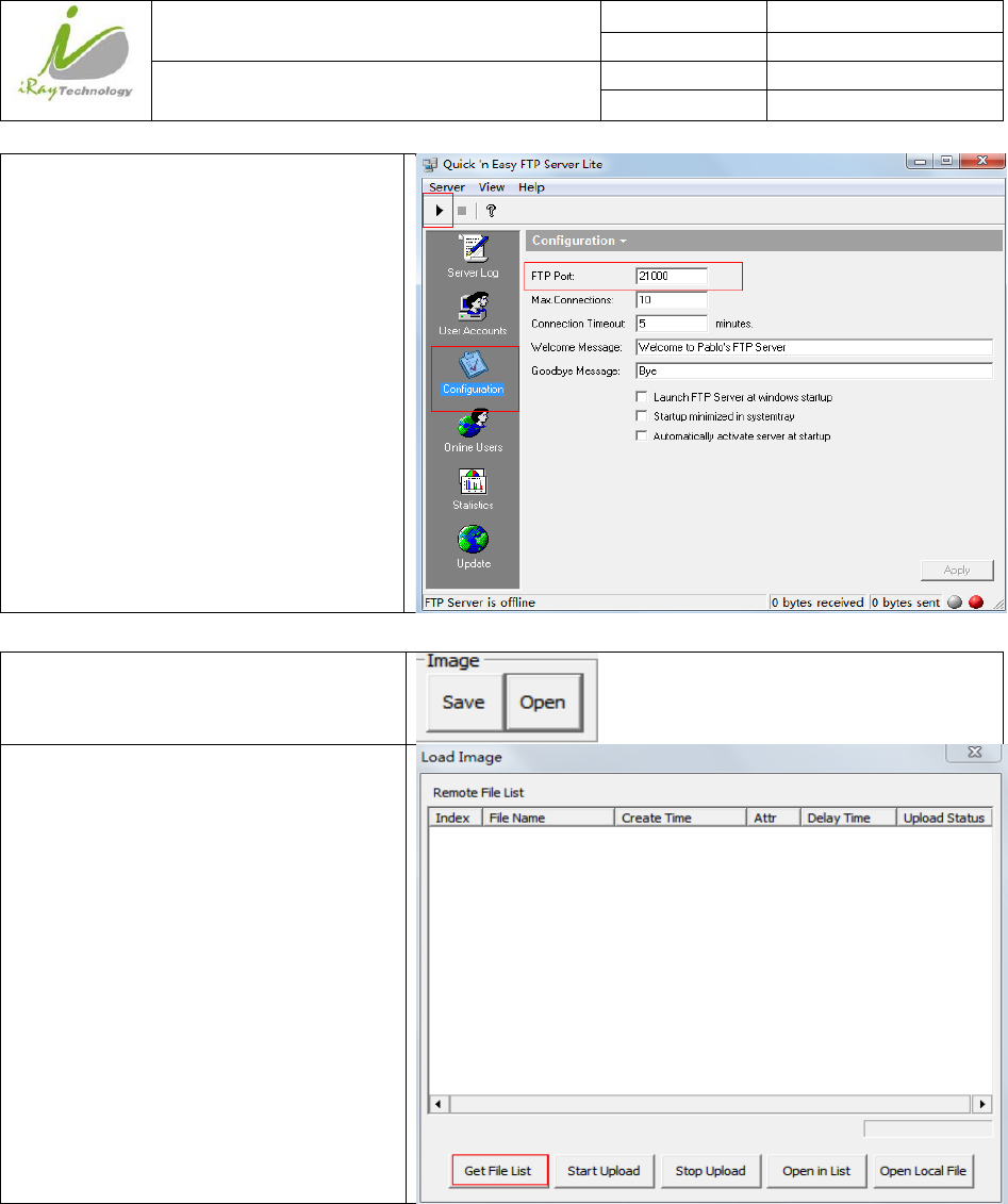
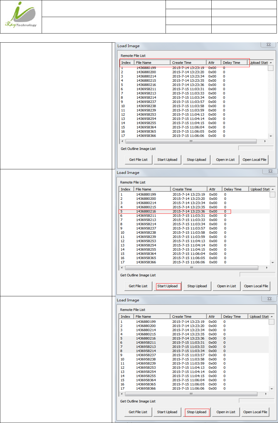
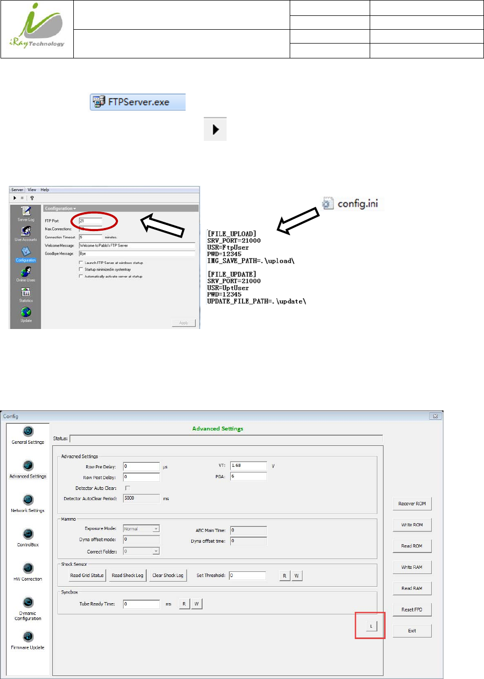
4.7.2 PanelImageUpload
Before panel image uploading, FTP server is necessary.
Make sure firewall is closed
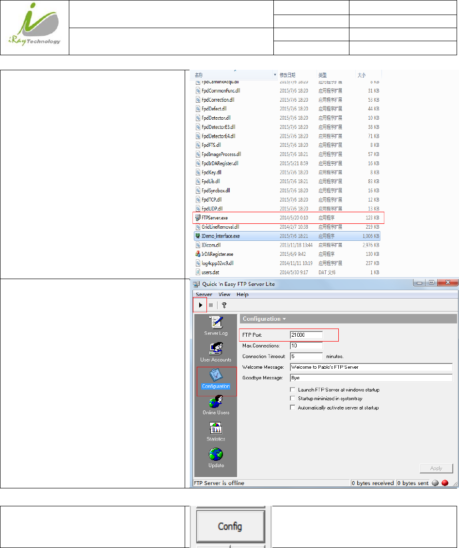
Start “FTPServer.exe”
iRay Technology (Shanghai) Ltd. Doc N0. 037‐201‐02
Version A1
Mars1717VUser’sManual Date 2015.11.06
Page 83/141
Page 83
Choose “Configuration”;
Set FTP Port “21000”;
Click “Start” button;
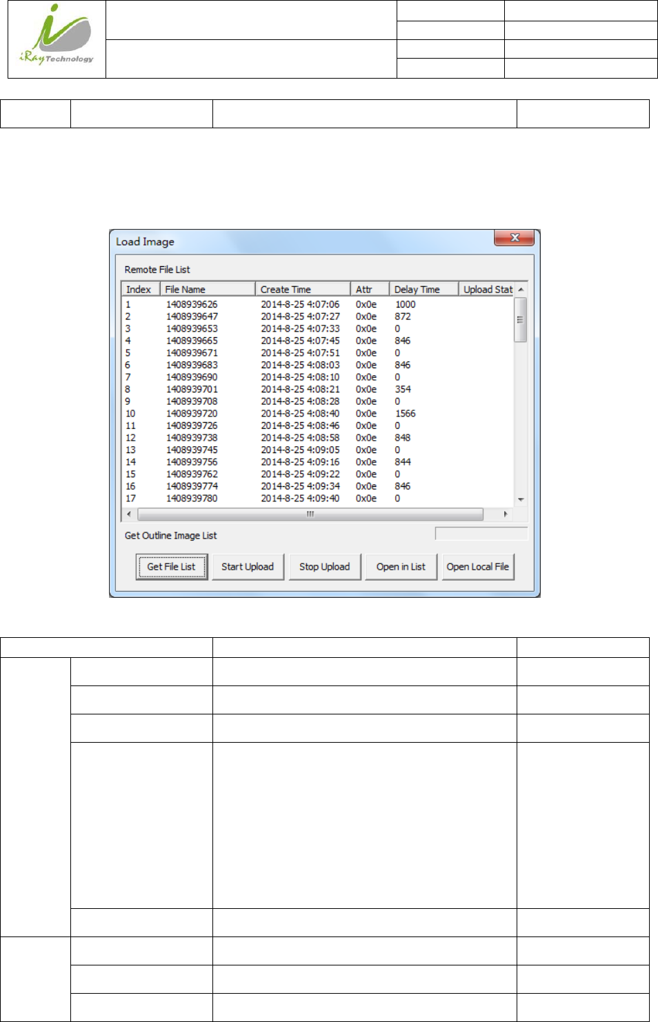
Panel Image is uploaded as following.
Click “Open”
Click “Get File List”
iRay Technology (Shanghai) Ltd. Doc N0. 037‐201‐02
Version A1
Mars1717VUser’sManual Date 2015.11.06
Page 84/141
Page 84
Images stored in panel would be shown in
the list. From the list, user could check
basic information of images
Select images user wants;
Click “Start Upload”;
Images would be uploaded to
*/idemo/upload
If user want to upload multiple images,
select multiple images, click “start
upload”, during uploading, user could
click “stop upload” to stop uploading
iRay Technology (Shanghai) Ltd. Doc N0. 037‐201‐02
Version A1
Mars1717VUser’sManual Date 2015.11.06
Page 85/141
Page 85
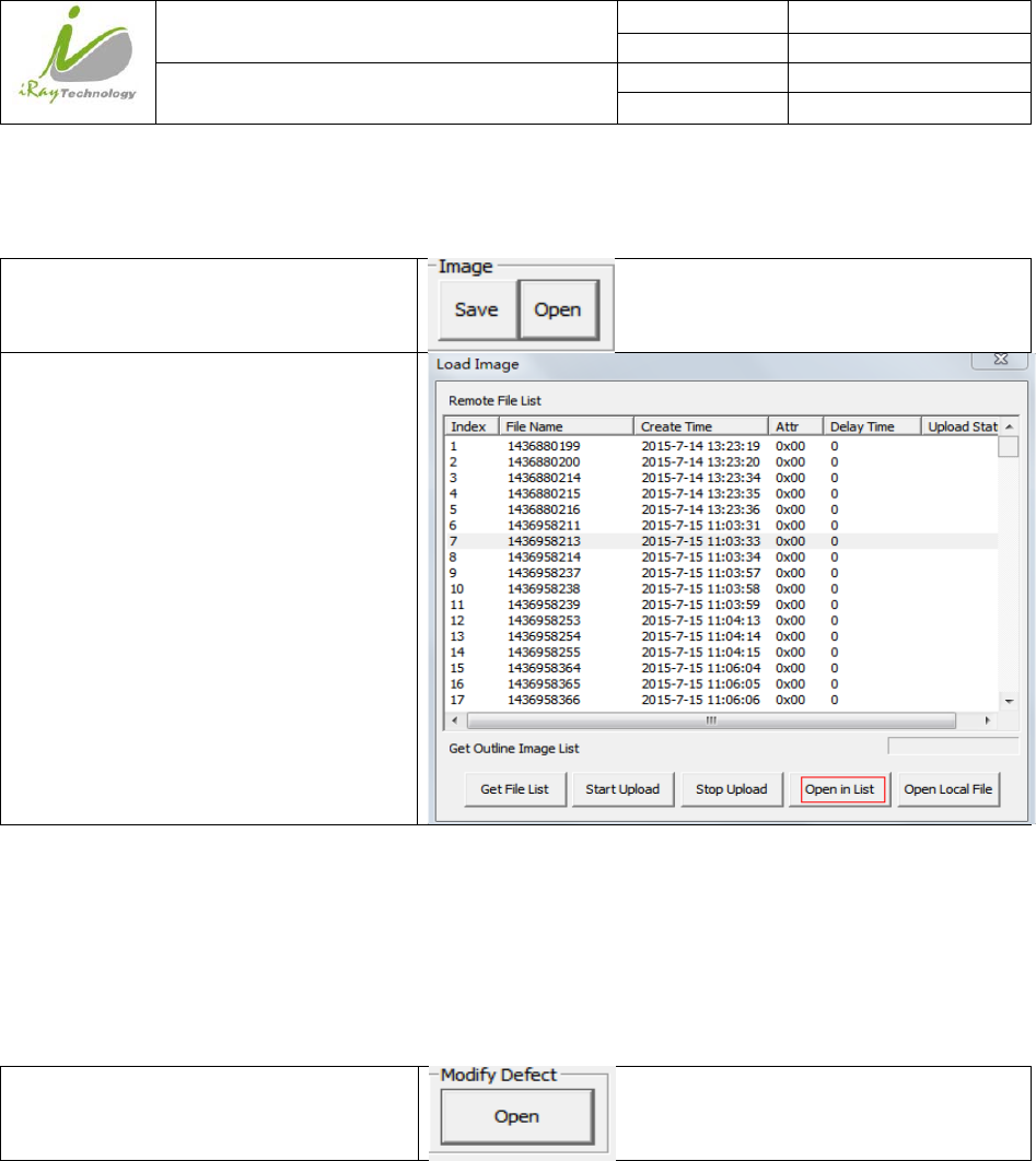
4.7.3 PanelImageCheck
If user wants to check images stored in panel immediately, see below
Click “Open”
Select image user need;
Click “open in list”
4.8 DefectTemplateCheckandModification
Idemo provides function to check defect template. If defect template has updates, user could add and delete
defect pixel or defect lines by modifying defect template opened.
4.8.1 DefectTemplateCheck
Click “Open”
iRay Technology (Shanghai) Ltd. Doc N0. 037‐201‐02
Version A1
Mars1717VUser’sManual Date 2015.11.06
Page 86/141
Page 86
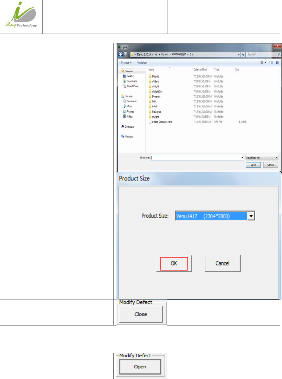
Select defect template;
Click “open”;
Select Product Size “Venu1417
(2304*2800);
Click “OK”, Defect template is shown on
screen;
Click “Close” to close Defect template
4.8.2 DefectTemplateModification
Click “Open”
iRay Technology (Shanghai) Ltd. Doc N0. 037‐201‐02
Version A1
Mars1717VUser’sManual Date 2015.11.06
Page 87/141
Page 87
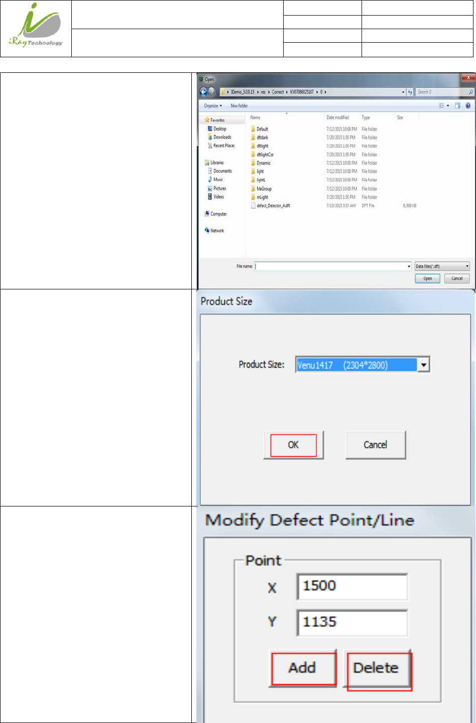
Select Defect Template;
Click “Open”;
Set product size “Venu1417 (2304*2800);
Click “OK”
If there is new defect pixel, input
coordinate, click “Add”;
If pixel is labeled as defect by mistake,
input coordinate, click “Delete”
iRay Technology (Shanghai) Ltd. Doc N0. 037‐201‐02
Version A1
Mars1717VUser’sManual Date 2015.11.06
Page 88/141
Page 88
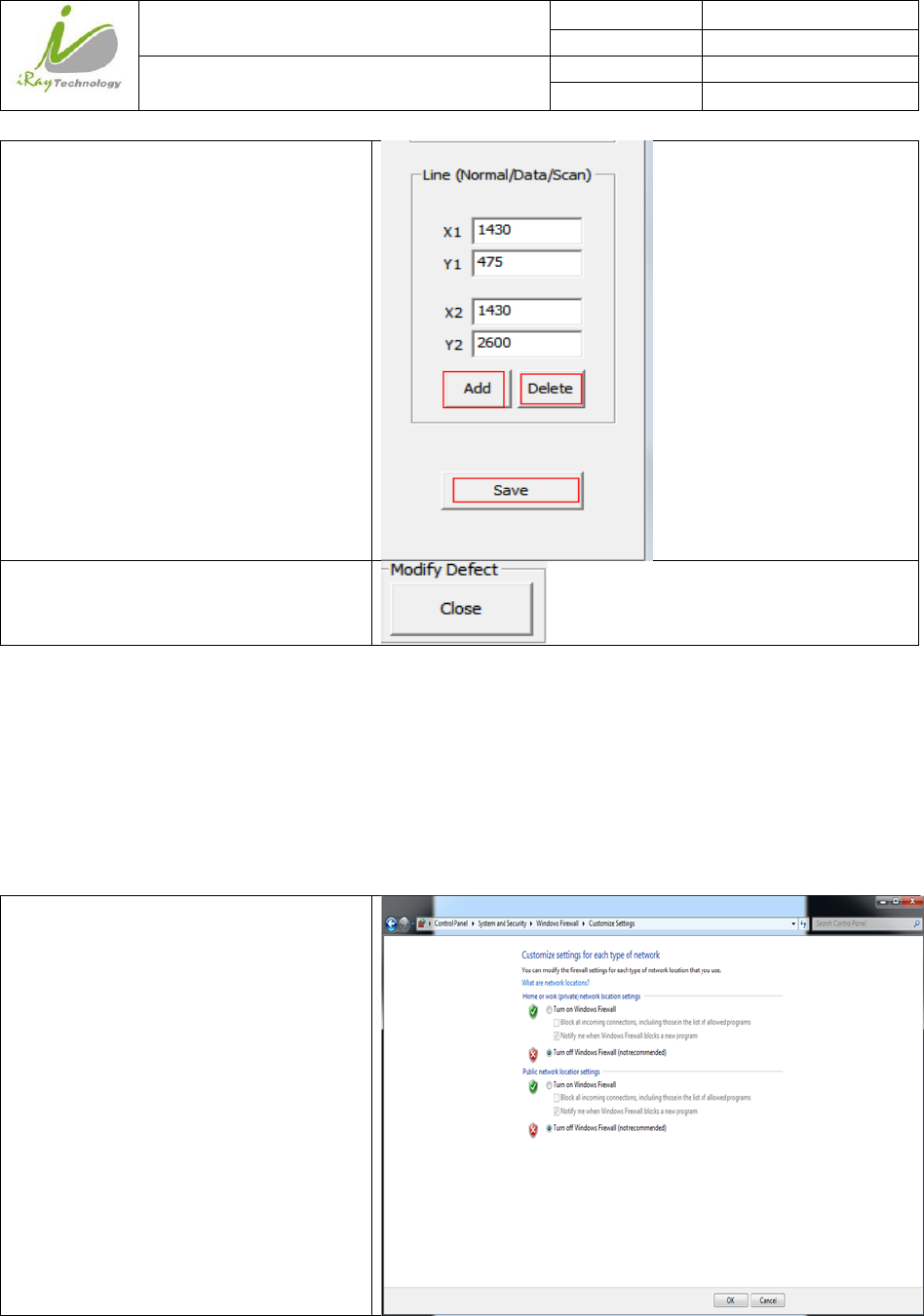
If there is new defect line, input
coordinate, click “Add”;
If line is labeled as defect by mistake,
input coordinate, click “Delete”
Click “Close”
4.9 CorrectionandCalibrationManagement
4.9.1 CorrectionandCalibrationtemplatesynchronization
Panel supports correction and calibration template storage. So template in panel could be uploaded to
Workstation, and template in Workstation could also be downloaded to panel. Before synchronization, FTP
server is necessary.
Make sure firewall is closed
iRay Technology (Shanghai) Ltd. Doc N0. 037‐201‐02
Version A1
Mars1717VUser’sManual Date 2015.11.06
Page 89/141
Page 89
Start “FTPServer.exe”
Choose “Configuration”;
Set FTP Port “21000”;
Click “Start” button;
Click “Config”
iRay Technology (Shanghai) Ltd. Doc N0. 037‐201‐02
Version A1
Mars1717VUser’sManual Date 2015.11.06
Page 90/141
Page 90
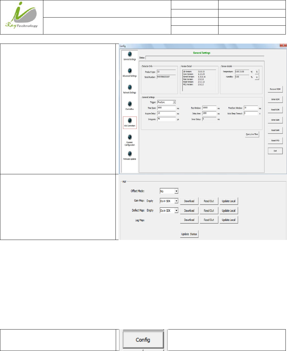
Select “HW Correction”
If user wants to download correction and
calibration template to panel. Click
“Download” from top to bottom;
If user wants to upload correction and
calibration template from panel. Click
“Read out” and “Update Local” from top
to bottom;
4.9.2 CorrectionandCalibrationmanagement
Panel supports two ways to do correction and calibration. Software Correction and Calibration defines the
scenario that Workstation completes all correction and calibration. If panel complete all correction and
calibration by itself, it is named as Hardware Correction and Calibration.
4.9.2.1 SoftwareCorrectionandCalibration
Click “Config”
iRay Technology (Shanghai) Ltd. Doc N0. 037‐201‐02
Version A1
Mars1717VUser’sManual Date 2015.11.06
Page 91/141
Page 91
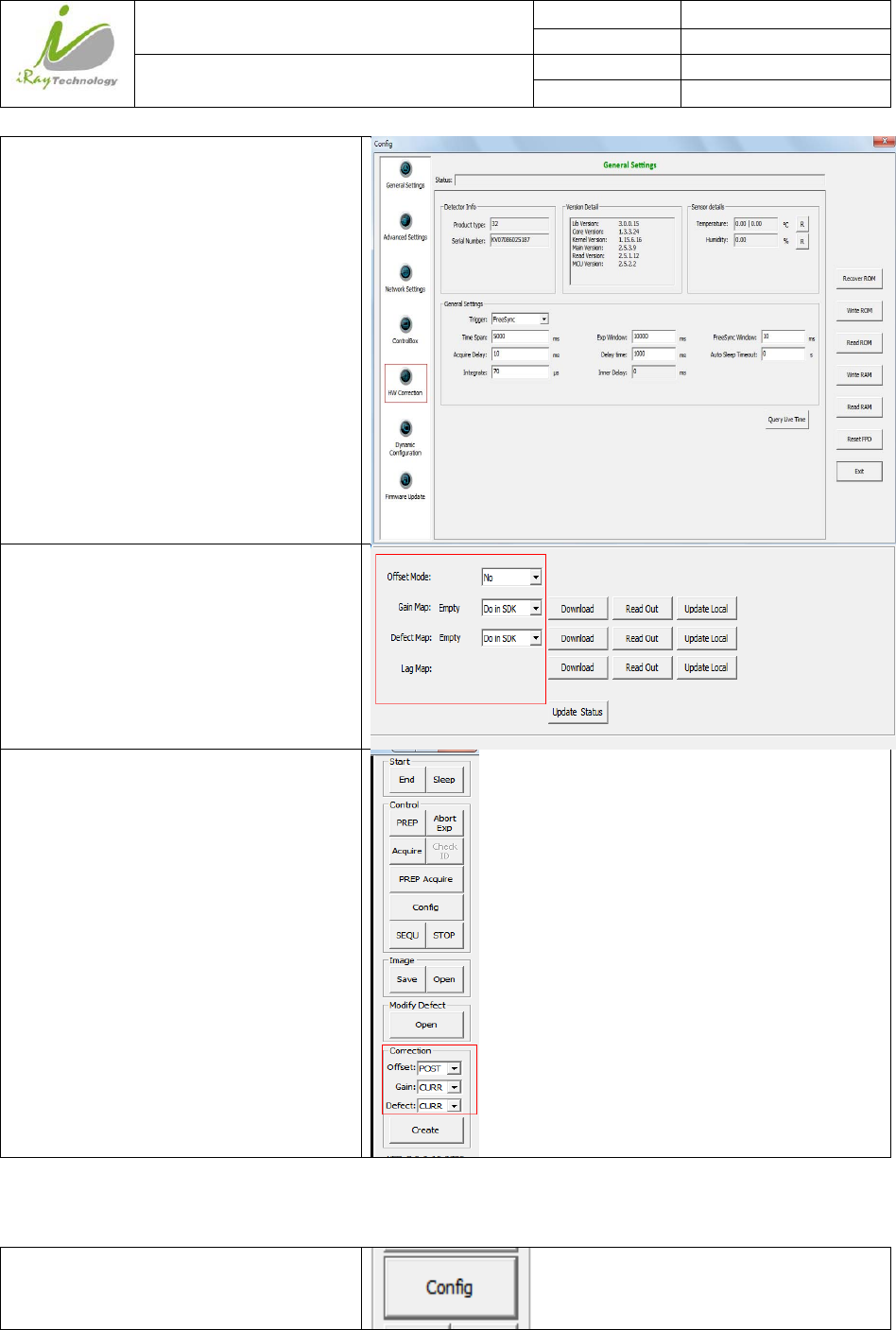
Select “HW Correction”;
Set Offset Mode “NO”;
Set Offset “POST”;
Set Gain “CURR”;
Set Defect “CURR”;
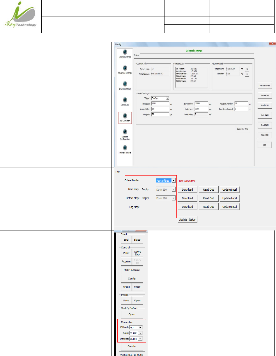
4.9.2.2 HardwareCorrectionandCalibrationManagement
Click “Config”
iRay Technology (Shanghai) Ltd. Doc N0. 037‐201‐02
Version A1
Mars1717VUser’sManual Date 2015.11.06
Page 92/141
Page 92
Select “HW Correction”;
Set Offset Mode “Post offset”;
Set Gain “CURR”;
Set Defect “CURR”;
4.10 SleepandWakeUp
Panel supports sleep and wake up operation. User can trigger sleep manually or automatically, but there is
only one way to wake up panel.
iRay Technology (Shanghai) Ltd. Doc N0. 037‐201‐02
Version A1
Mars1717VUser’sManual Date 2015.11.06
Page 93/141
Page 93
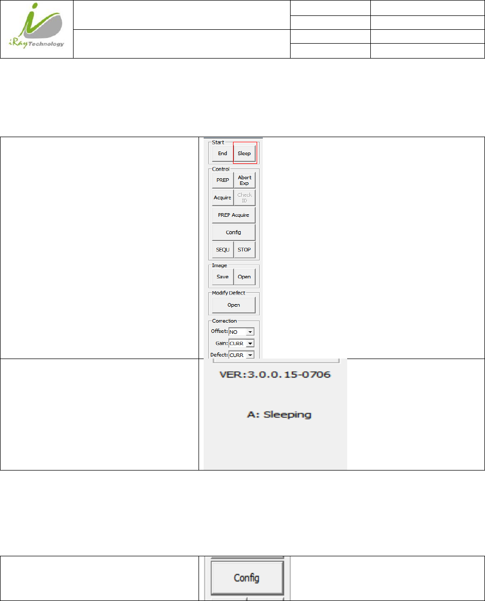
4.10.1 Sleep
4.10.1.1 ManualSleep
Click “Sleep”, panel will go to sleep
immediately
Message box shows that panel is sleeping
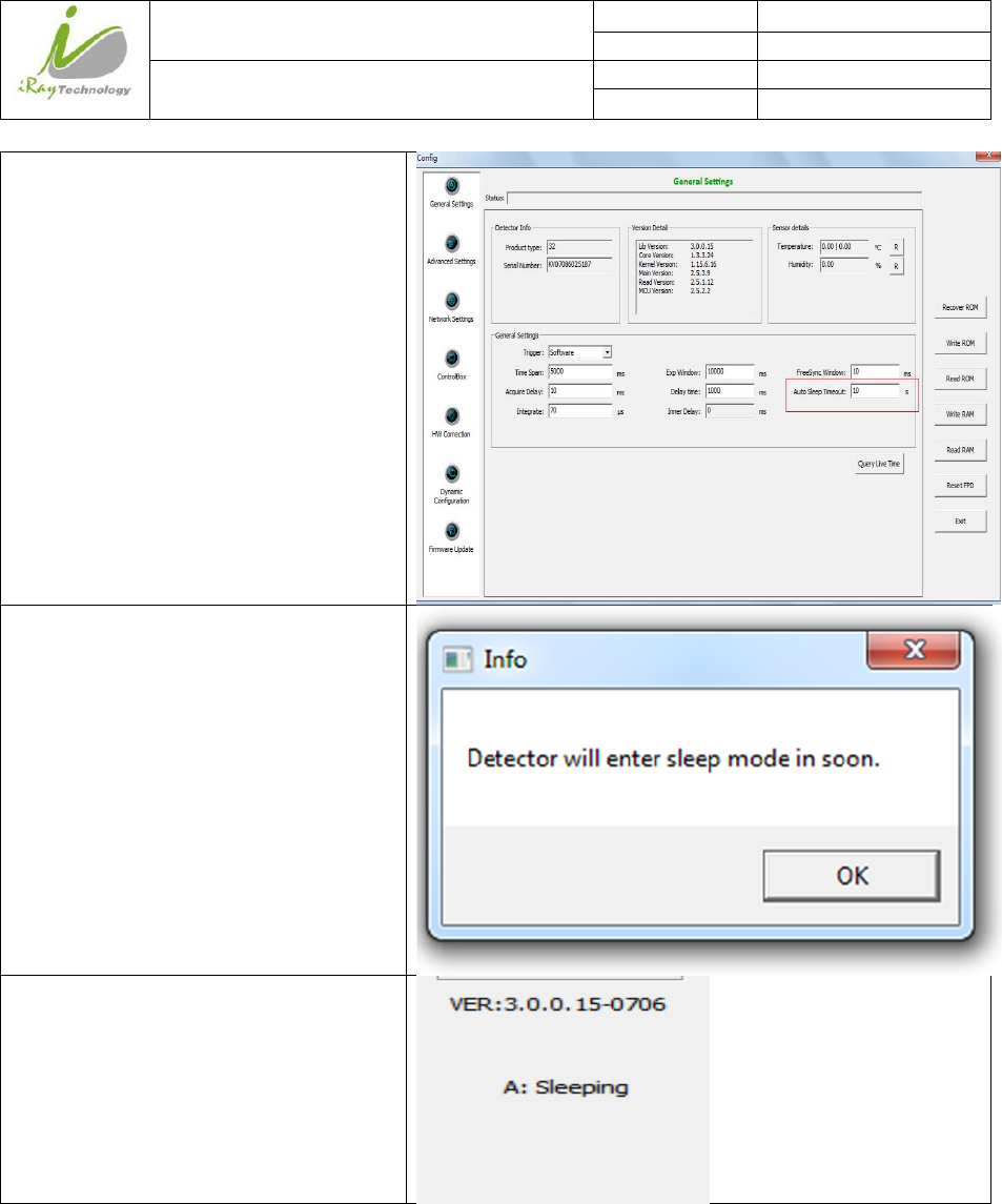
4.10.1.2 AutomaticSleep
To go to sleep automatically, user should set the time flag first. If panel detects that there is no operation in
time flag, panel would go to sleep. If time flag is set zero, panel would not go to sleep automatically.
Click “Config”
iRay Technology (Shanghai) Ltd. Doc N0. 037‐201‐02
Version A1
Mars1717VUser’sManual Date 2015.11.06
Page 94/141
Page 94
Set “auto sleep timeout” value user need
If there is no operation in time flag user
sets, panel would go to sleep
Message box shows that panel is sleeping
iRay Technology (Shanghai) Ltd. Doc N0. 037‐201‐02
Version A1
Mars1717VUser’sManual Date 2015.11.06
Page 95/141
Page 95
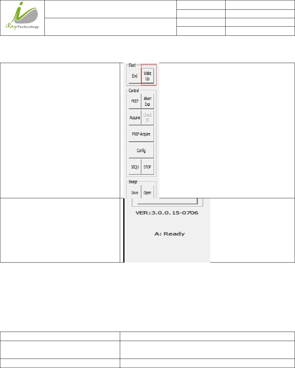
4.10.2 WakeUp
If panel is sleeping, click “Wake Up”
Message box shows that panel is ready
4.11 FirmwareUpdate
Panel supports updating firmware. If user wants to update new firmware, see below
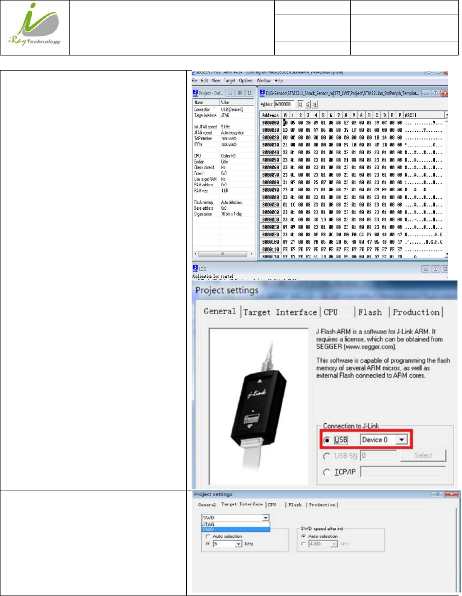
4.11.1 MCUUpdate
If current MCU version is 2.5.1.*, we should follow instruction below.
Open “mini Cover” /
Remove original Ethernet cable, insert J-
link download cable
/
Start J-flash ARM /
iRay Technology (Shanghai) Ltd. Doc N0. 037‐201‐02
Version A1
Mars1717VUser’sManual Date 2015.11.06
Page 96/141
Page 96
Click “file->open data file”
Click “option->project setting”,
Set “connection to J-link” USB mode
Click “Target Interface”, Choose “SWD”
iRay Technology (Shanghai) Ltd. Doc N0. 037‐201‐02
Version A1
Mars1717VUser’sManual Date 2015.11.06
Page 97/141
Page 97
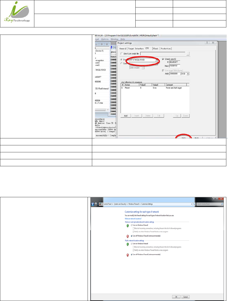
Click “ CPU”;
Select “ST STM32L151C8”;
Click “Target->Connect” /
Click “Target-> Erase” /
Click “Target->Program” /
Click “Target->Start Application” /
Note:1. Make sure panel is powered up.
If current MCU version is 2.5.2.*, Please refer to 4.10.2 and 4.10.3 for upgrading.
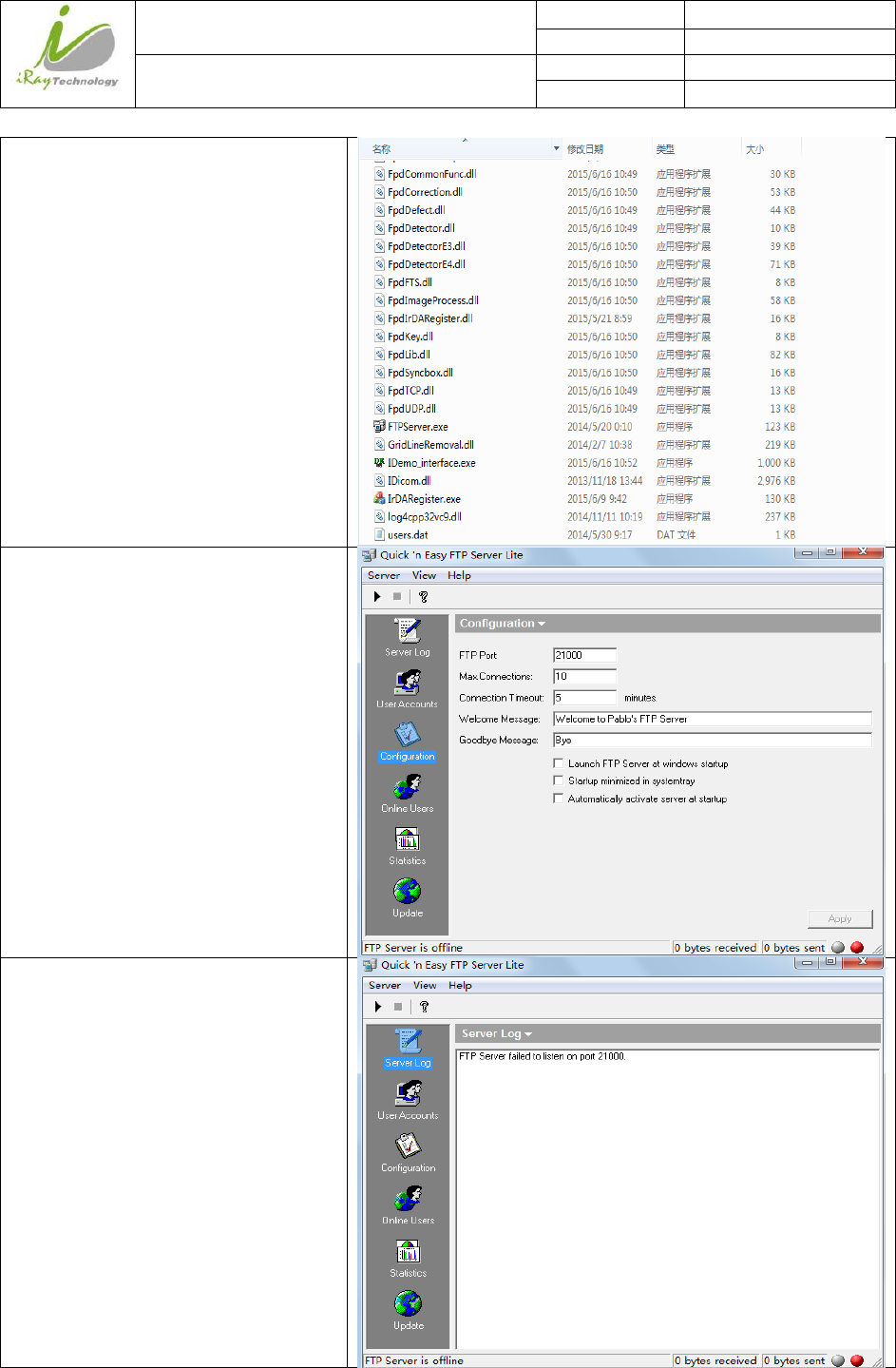
4.11.2 FTPServer
Make sure firewall is closed
iRay Technology (Shanghai) Ltd. Doc N0. 037‐201‐02
Version A1
Mars1717VUser’sManual Date 2015.11.06
Page 98/141
Page 98
Click On “FTPServer.exe”
Choose “Configuration”, set “FTP Port”
21000, others as default
Start FTP Server
iRay Technology (Shanghai) Ltd. Doc N0. 037‐201‐02
Version A1
Mars1717VUser’sManual Date 2015.11.06
Page 99/141
Page 99
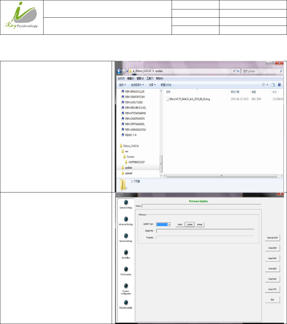
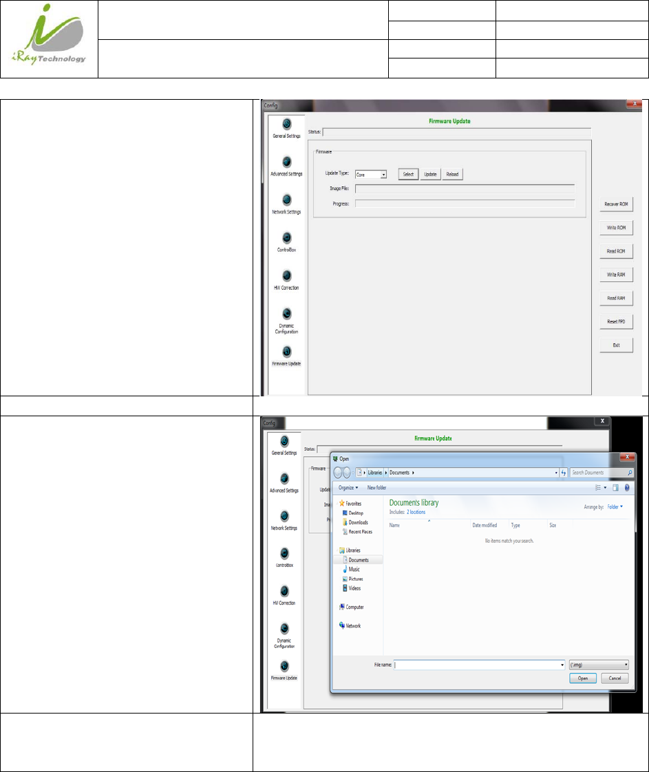
4.11.3 FirmwareUpdate
Put update file in the directory of
“*\idemo\update”
Click “Config”, Choose Firmware
Update
iRay Technology (Shanghai) Ltd. Doc N0. 037‐201‐02
Version A1
Mars1717VUser’sManual Date 2015.11.06
Page 100/141
Page 100
Choose Update Type “core1”
Click “Select”, choose right update file2
Click “update”, waiting for message
box3
Click message box, waiting for end of
rebooting4;
Panel finishes rebooting, Click “OK” 5
/
Note:
1. It is not limited to “Core”, actually, other choice is also ok.
2. If it is MCU update, choose MCU image file. Otherwise, choose ALL-Image file, Please make sure update
file is selected, if not, panel will be not in use after updating.
3. There is a progress bar for indication. Make sure battery is inserted and battery capacity is over 25%
4. This rebooting function is controlled by panel itself. It has the same function with “ Reset FPD”
5. Please make sure Idemo show “ Ready”. It can also be checked by click “ Config” button, there is
firmware version.

iRay Technology (Shanghai) Ltd. Doc N0. 037‐201‐02
Version A1
Mars1717VUser’sManual Date 2015.11.06
Page 101/141
Page 101
4.12 Shortcut
iDemo supports some shortcuts as follows:
Double-click the left mouse button, the image displayed in center and with
maximum size.
Double-click the right mouse button, the window level and width adjusted to
WL:8191/WW:16383.
Drag the left mouse button, drag the image displayed.
Lateral-drag the right mouse button to adjust the window width, and vertical-
drag the right mouse button to adjust the window level.
F3 Key: Quickly adjust the image window width and window level.
iRay Technology (Shanghai) Ltd. Doc N0. 037‐201‐02
Version A1
Mars1717VUser’sManual Date 2015.11.06
Page 102/141
Page 102
4.13 Software
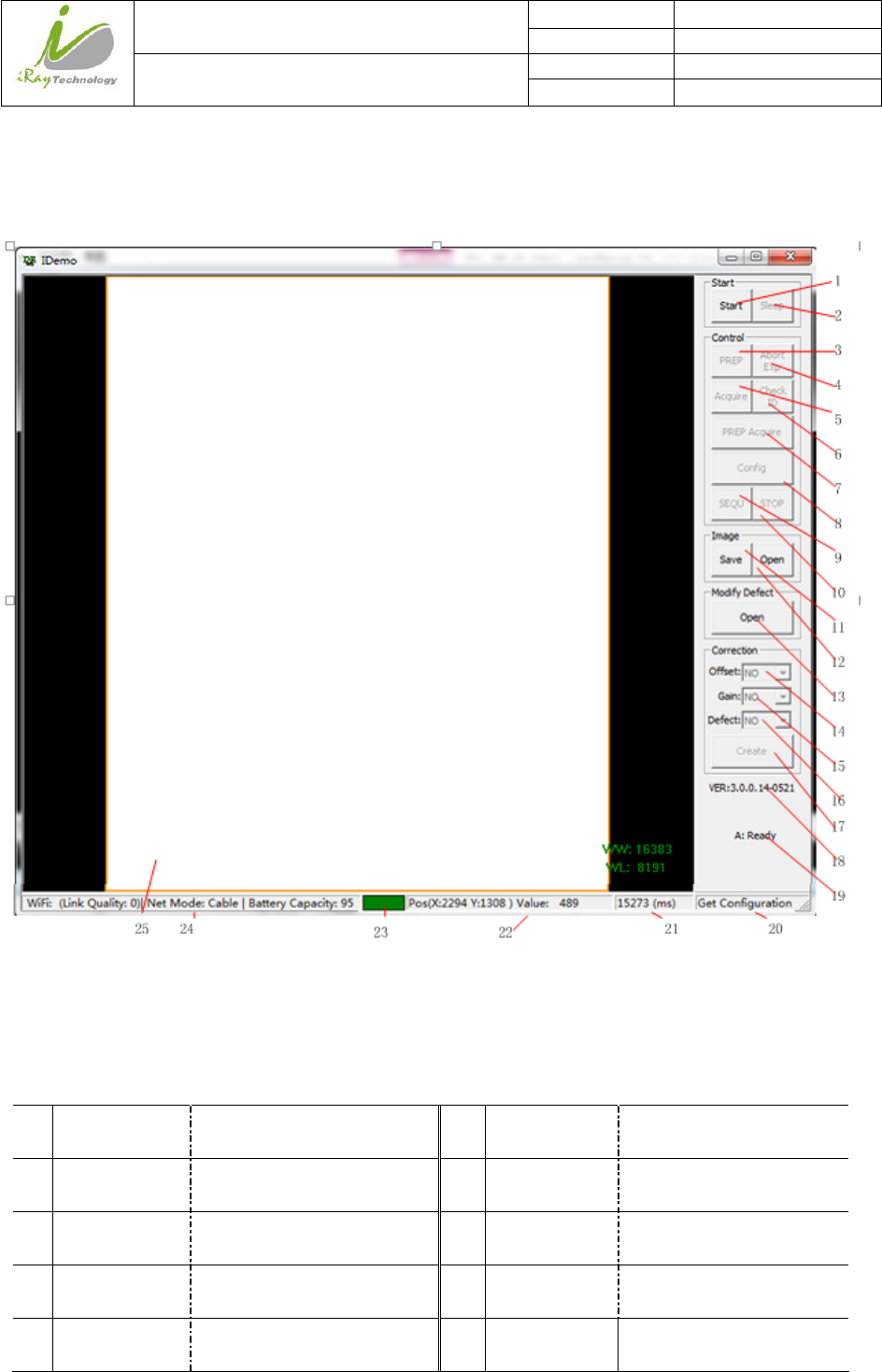
4.13.1 MainGUI
iRay provides test tools, such as iDemo for testing the basic performance of detector. It can connect the
detector, acquire image, image correct and calibrate.
Function description of regions and buttons within the main window as follows:
1 Start/End Load or unload NIC device
driver
13 Open/Close Open or close defect map
2 Sleep/Wake Sleep or wake up panel 14 Offset Open or close software
post offset
3 Prep Clear lags of the panel 15 Gain Open or close gain
calibration
4 Abort Exp Close exposure Window 16 Defect Open or close defect
correction
5 Acquire Acquire an image without
clearance
17 Create Generate gain template
and defect template

iRay Technology (Shanghai) Ltd. Doc N0. 037‐201‐02
Version A1
Mars1717VUser’sManual Date 2015.11.06
Page 103/141
Page 103
6 Check ID Check panel SN 18 Version of the idemo
7 Prep Acquire Clear lags and acquire an
image
19 Status of the idemo
8 Config Configure the panel 20 Panel feedback message
9 Sequ Start acquiring images
continually
21 Acquisition interval between two images
10 Stop Stop acquiring images
continually
22 Pixel X/Y coordinate and gray scale value
of Pixel(14 bit)
11 Save Save images continually or
save an image
23 Image acquisition instruction box
12 Open Open local images(.DCM)
or open images in the panel
24 WiFi signal and battery capacity indication
25 Region of image display
4.13.2 MessageBox
4.13.2.1 StatusBox
Status box defines the current status of panel.
Value Description
Offline Idemo loose connection with panel, it does not receive heart beat
Ready Idemo builds connection with panel, panel is ready for receiving new operation
Busy Idemo builds connection with panel, panel is busying on the last operation, it can
not be interrupted
Sleeping Idemo builds connection with panel, panel has gone in sleep
Waking Idemo builds connection with panel, panel is being wake up
Timeout Command executes overtime

iRay Technology (Shanghai) Ltd. Doc N0. 037‐201‐02
Version A1
Mars1717VUser’sManual Date 2015.11.06
Page 104/141
Page 104
4.13.2.2 FeedbackBox
Feedback box shows feedback message from panel.
4.13.2.3 AcquisitionIntervalBox
Acquisition Interval Box shows the time between two image acquired currently.
4.13.2.4 CoordinateandGrayScaleBox
Coordinate and Cray Scale Box show the coordinate and gray scale of mouse.
4.13.2.5 ImageAcquisitionBox
Image Acquisition Box shows whether image is uploading
Color Description
Red Image is uploading from panel
Green others
4.13.2.6 BatteryandConnectionBox
Battery and Connection Box shows battery capacity, wireless signal level and wire connection.
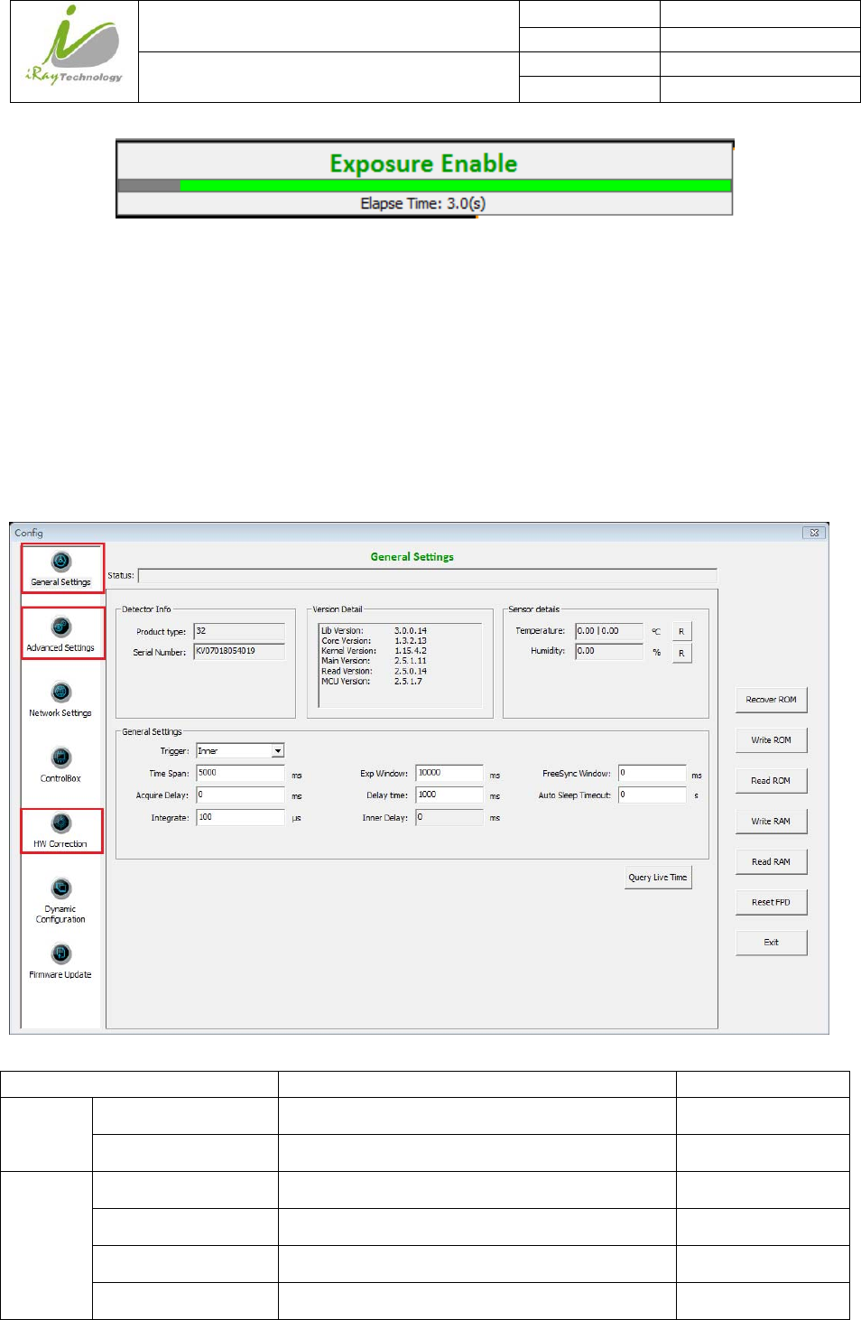
4.13.2.7 ProgressBar
Progress Bar defines as following.
iRay Technology (Shanghai) Ltd. Doc N0. 037‐201‐02
Version A1
Mars1717VUser’sManual Date 2015.11.06
Page 105/141
Page 105
If progress bar is Green when shooting X-ray, image quality is acceptable, otherwise image quality would
degrade.
4.13.3 ConfigurationGUI
4.13.3.1 GeneralSettings
Item Description Modify
Detector
Info
Product type Type of panel product NO
Serial Number Serial number of the panel NO
Version
Detail
Lib Version Version number of idemo NO
Core Version Version number of ARM application NO
Kernel Version Version number of ARM OS Kernel NO
Main Version Version number of Core FPGA NO

iRay Technology (Shanghai) Ltd. Doc N0. 037‐201‐02
Version A1
Mars1717VUser’sManual Date 2015.11.06
Page 106/141
Page 106
Read Version Version number of Read FPGA NO
MCU Version Version number of MCU NO
Sensor
details
Temperature Panel inner temperature(Read Board and Core
Board)
NO
Humidity Panel inner Humidity NO
General
Settings
Trigger Detector trigger mode:
1.Outer
2.Inner
3.Software
4.PREP
5.Service
6.FreeSync (Default)
YES
Time Span This parameter is used only in continual
acquisition. The time span is the time interval
between two nearby acquisition process
YES
Exp Window Exposure window is used in Inner mode, it
defines the time for X-ray shooting.
YES
FreeSync Window Not Used YES
Acquire Delay Delay time before image acquisition. YES
Delay time Exposure Window in Isync Plus mode/Delay
time between clearance and acquisition in other
mode.
YES
Auto Sleep Timeout Time span of idle before going to sleep YES
Integrate The integration time for the photo diode NO
Inner Delay The real delay time between clearance and
acquisition most recently.
NO
Button Recover ROM Recover configuration to factory setting /
Write ROM Write configuration data into nonvolatile memory /
Read ROM Read configuration data from nonvolatile
memory
/
Write RAM Write configuration data into volatile memory /
Read RAM Read configuration data into volatile memory /
Reset FPD Reboot the panel /
iRay Technology (Shanghai) Ltd. Doc N0. 037‐201‐02
Version A1
Mars1717VUser’sManual Date 2015.11.06
Page 107/141
Page 107
Exit Exit configuration GUI /
Query Live Time Check the active time of panel /
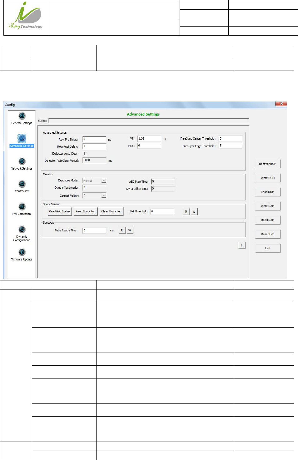
4.13.3.2 AdvancedSettings
Item Description Modify
Advacned
Settings
Row Pre Delay Delay time before acquiring row data YES
VT Voltage corresponding to the charge
compensation
YES
Freesync Center
Threhold
Not used
YES
Row Post Delay Delay time after acquiring row data YES
PGA Integrator capacitor range. YES
Freesync Edge
Threhold
Not used
YES
Detector Auto Clear Set the detector in auto clear mode NO
Detector Auto Clear
Period
Auto clear period for panel
NO
Mammo Exposure Mode Not used NO
AEC Main Time Not used NO
iRay Technology (Shanghai) Ltd. Doc N0. 037‐201‐02
Version A1
Mars1717VUser’sManual Date 2015.11.06
Page 108/141
Page 108
Dyna Offset Mode Not used NO
Dyna Offset Time Not used NO
Correct Folder Not used NO
Shock
Sensor
Read Grid Status Not used NO
Read Shock log Read shock sensor log NO
Clear Shock Log Clear shock sensor log NO
Set Threshold Shock sensor threshold YES
R Read Shock sensor threshold from panel NO
W Write Shock sensor threshold to panel NO
Syncbox Tube Ready Time Not used NO
R Not used NO
W Not used NO
Button L Read Log from panel NO
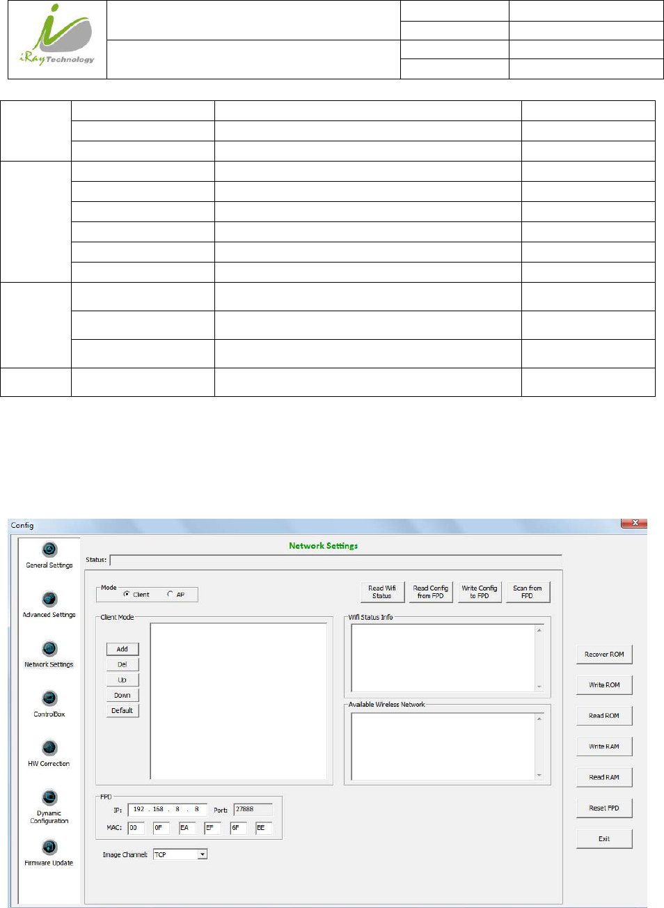
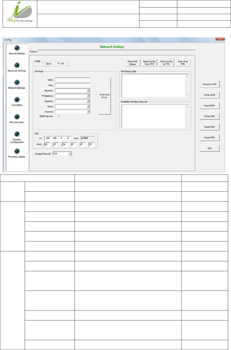
4.13.3.3 NetworkSettings
Client Mode:
AP Mode:
iRay Technology (Shanghai) Ltd. Doc N0. 037‐201‐02
Version A1
Mars1717VUser’sManual Date 2015.11.06
Page 109/141
Page 109
Item Description Modify
Mode Client Set panel in client mode NO
AP Set panel in AP mode NO
Client
Mode
Add Add available wireless AP account NO
Del Delete Exist wireless AP account NO
Up Wireless AP account move up NO
Down Wireless AP account move down NO
Default Set AP account as default connection NO
AP Mode SSID Wireless AP SSID when panel in AP mode YES
Key Wireless AP Key when panel in AP mode YES
Security Wireless AP Security method when panel in AP
mode
YES
Frequency Wireless AP frequency(2.4GHz and 5GHz) when
panel in AP mode
YES
Country Wireless AP Country when panel in AP mode YES
Band Wireless AP Band(HT20 and HT40) when panel
in AP mode
YES
Channel Wireless AP Channel when panel in AP mode YES
iRay Technology (Shanghai) Ltd. Doc N0. 037‐201‐02
Version A1
Mars1717VUser’sManual Date 2015.11.06
Page 110/141
Page 110
DHCP Server DHCP function when panel in AP mode YES
Scan Local Wlan Scan local wifi signal when panel in AP mode YES
FPD IP Network IP address of panel YES
Port Network Port of panel NO
MAC Network MAC address of panel YES
Image Channel Network protocol of panel YES
Button Read Wifi Status Read wireless module status from panel NO
Read Config from
FPD
Read wireless module setting from panel
NO
Write Config to FPD Write wireless module setting to panel NO
Scan from FPD Scan Wifi signal by panel NO
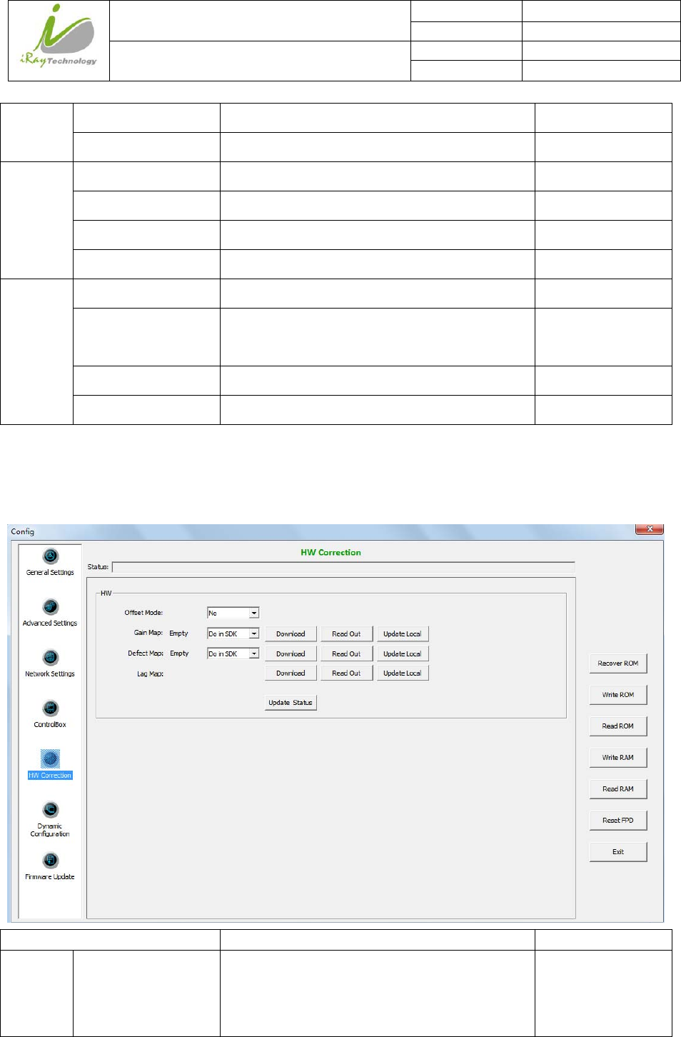
4.13.3.4 HWCorrection
Item Description Modify
HW Offset Mode Hardware offset mode of panel
NO: no hardware offset mode
Pre: hardware pre-offset mode
YES

iRay Technology (Shanghai) Ltd. Doc N0. 037‐201‐02
Version A1
Mars1717VUser’sManual Date 2015.11.06
Page 111/141
Page 111
Post: hardware post-offset mode
Gain Map Gain calibration mode of panel
Do in SDK: software gain calibration
Do in HW: hardware gain calibration
NO
Defect Map Defect correction mode of panel
Do in SDK: software defect correction
Do in HW: hardware defect correction
NO
Lag Map Lag correction of panel NO
Download Download correction and calibration template to
panel
NO
Read out Upload correction and calibration template from
panel
NO
Update local Replace local correction and calibration template
with template uploaded currently
NO
Update status Get correction and calibration configuration from
panel
NO
iRay Technology (Shanghai) Ltd. Doc N0. 037‐201‐02
Version A1
Mars1717VUser’sManual Date 2015.11.06
Page 112/141
Page 112
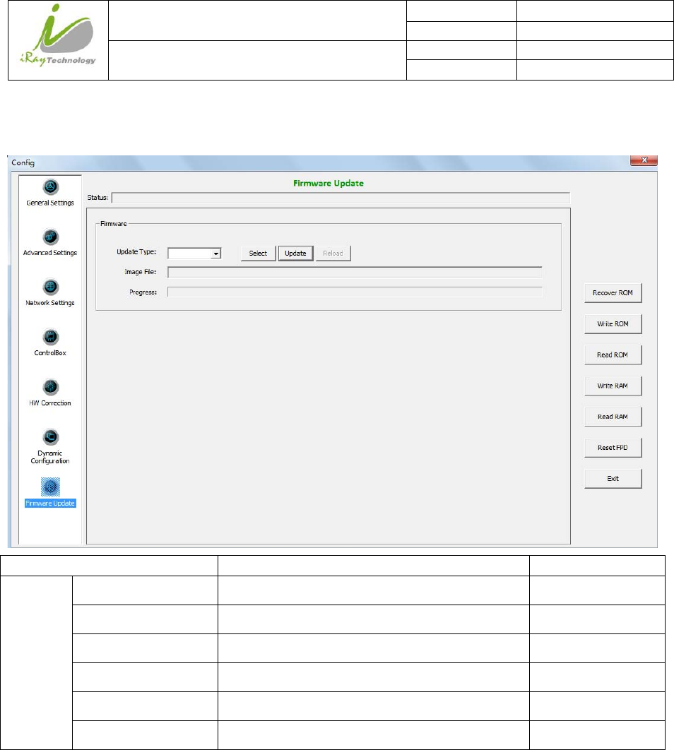
4.13.3.5 FirmwareUpdate
Item Description Modify
Firmware Update Type Not used YES
Image File Local address of update file NO
Progress Progress bar of updating NO
Select Select update file NO
Update Start update NO
Reload Reload firmware of panel NO
iRay Technology (Shanghai) Ltd. Doc N0. 037‐201‐02
Version A1
Mars1717VUser’sManual Date 2015.11.06
Page 113/141
Page 113
4.13.4 CorrectionandCalibration
4.13.4.1 Gain Calibration
Item Description Modify
Expected
Average
Expected Gray Value Not used YES
New Gain Point Start generating gain template NO
New
Point
Selected Gain Number of selected gain point NO
Current Average Average value of the complete image NO
Center Average Average value of the image in center ROI
( 100X100)
NO
Select Select and save current gain point NO
Button Prep Send “Clear” command to panel NO
Acquire Send “Acquire” command to panel NO
Prep Acquire Send “Clear Acquire” command to panel NO
Create Gain Correct Start generating gain Calibration template NO
iRay Technology (Shanghai) Ltd. Doc N0. 037‐201‐02
Version A1
Mars1717VUser’sManual Date 2015.11.06
Page 114/141
Page 114
File
4.13.4.2 DefectCorrection
Item Description Modify
Create
Light File
Current Current sequence of defect point NO
Start creating Start defect point acquisition NO
Auto completion Automatically acquire defect point NO
Button Refresh HW Offset
Template
Updating pre-offset template in panel NO
Prep Send “Clear” command to panel NO
Acquire Send “Acquire” command to panel NO
Prep Acquire Send “Clear Acquire” command to panel NO
Create Offset Generate pre-offset template NO
iRay Technology (Shanghai) Ltd. Doc N0. 037‐201‐02
Version A1
Mars1717VUser’sManual Date 2015.11.06
Page 115/141
Page 115
Create Defect Generate Defect correction template NO
4.13.5 ImageCheckandupload
Item Description Modify
Remote
File List
Index Sequence number of image NO
File name Name of image in panel NO
Create Time Acquisition time of image in panel NO
Attr Image label
0x01—Do Offset
0x02—Do Gain
0x04—Do Most gain
0x08—Do Defect
0x10—Post Offset Raw Image
NO
Delay Time Time between clear and image acquisition NO
Button Get File List Get file list from panel NO
Start Upload Start uploading image selected NO
Stop Upload Stop uploading process NO
iRay Technology (Shanghai) Ltd. Doc N0. 037‐201‐02
Version A1
Mars1717VUser’sManual Date 2015.11.06
Page 116/141
Page 116
Open in List Open image selected NO
Open Local File Open local images in Workstation NO
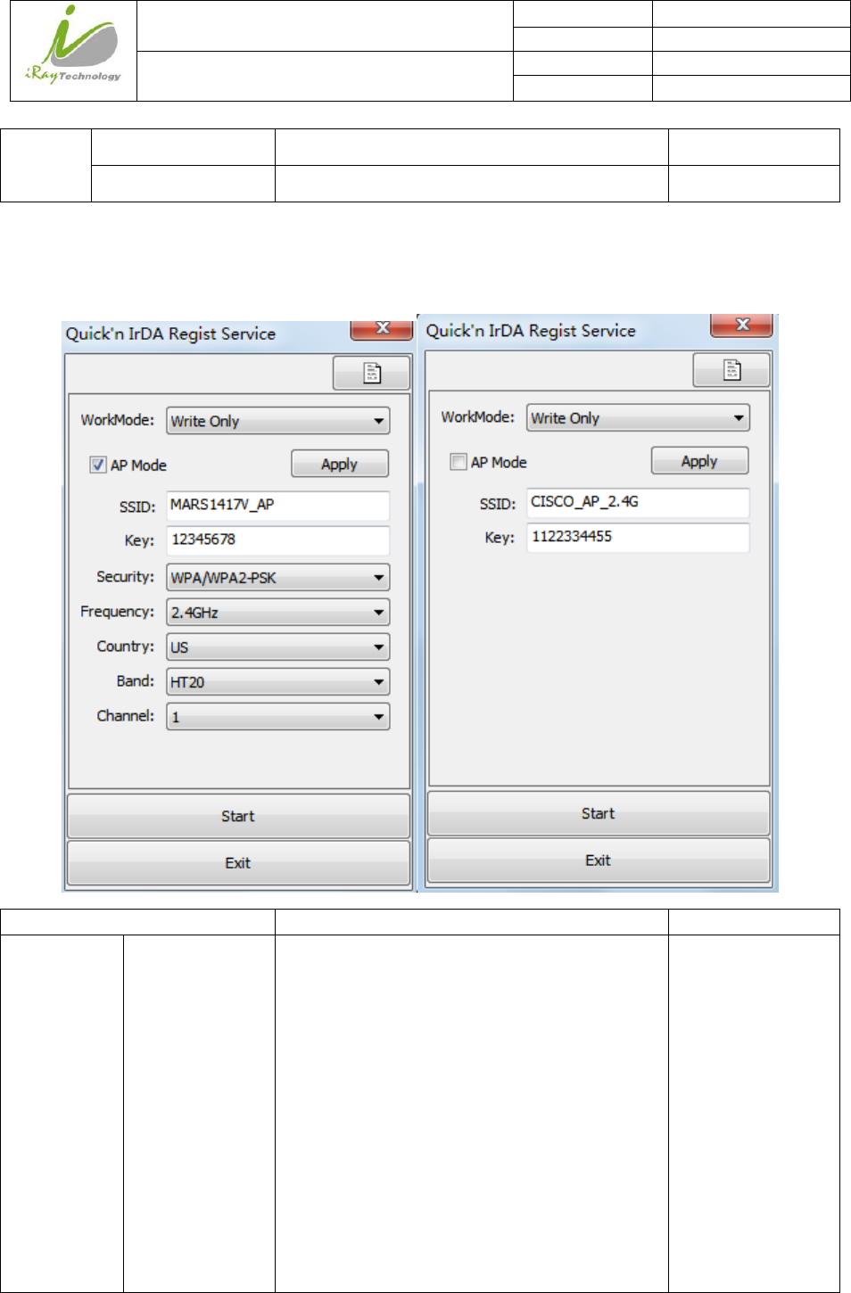
4.13.6 InfraredRegistration
Item Description Modify
/ Work Mode Work mode of infrared registration tools
Write Only: infrared registration tools is allowed
to write to panel
Read Only: infrared registration tools is allowed
to read from panel
Read & Write: infrared registration tools is
allowed to read from panel and write to panel
Read &confirm by User: infrared registration
tools is allowed to read from panel and write to
panel only when confirmed by user
YES
iRay Technology (Shanghai) Ltd. Doc N0. 037‐201‐02
Version A1
Mars1717VUser’sManual Date 2015.11.06
Page 117/141
Page 117
AP Mode
Configuration
AP Mode Set panel in AP mode or Client mode YES
SSID Wireless AP SSID when panel in AP mode YES
Key Wireless AP Key when panel in AP mode YES
Security Wireless AP Security way when panel in AP
mode
YES
Frequency Wireless AP Frequency(2.4GHz and 5GHz)
when panel in AP mode
YES
Country Wireless AP Country Code when panel in AP
mode
YES
Band Wireless AP Band(HT20 and HT40) when panel
in AP mode
YES
Channel Wireless AP Channel when panel in AP mode YES
Client Mode
Configuration
SSID Wireless SSID when panel in Client mode YES
Key Wireless Key when panel in Client mode YES
Button Apply Save wireless parameter in infrared registration
tools
NO
Start Start write wireless parameter in panel NO
Exit Exit infrared registration tools NO

iRay Technology (Shanghai) Ltd. Doc N0. 037‐201‐02
Version A1
Mars1717VUser’sManual Date 2015.11.06
Page 118/141
Page 118
5 Regulatory Information
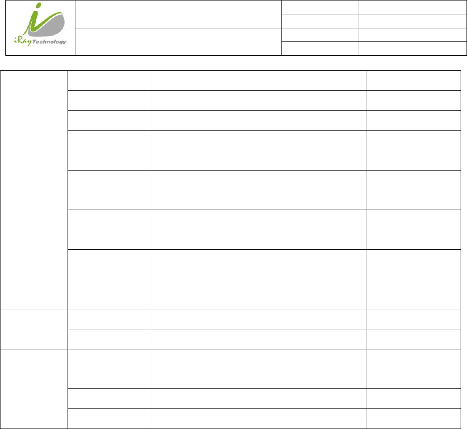
5.1 Medical equipment safety standards
Medical equipment classification
Type of protection against electrical shock Class I Equipment, using medical approved adaptor supply
Internally powered Equipment, using battery power supply
Degree of protection against electrical
shock
Without Applied Parts
Degree of protection against ingress of
water
IPX0 (Mars1717V)
IPX0 (Charger-KV)
Mode of operation Continuous operation
Flammable anesthetics Not suitable for use in the presence of a flammable
anesthetic mixture with air or with oxygen or nitrous oxide
Not suitable for use in the oxygen rich environment
Note: The product safety standards that apply to Mars1717V which includes the main units: detector and
charger-kv .
References harmonized standards under Directive 93/42/EEC
MDD (93/42/EEC) Medical Device Directive
EN ISO 13485:2012/EN
ISO 13485:2012/AC:2012
Medical devices --- Quality management systems ---
Requirements for regulatory purposes
EN ISO14971: 2012 Medical device – Application of risk management to medical
devices
EN 60601-1:2014 Medical electrical equipment -- Part 1: General requirements for
basic safety and essential performance
EN 60601-1-2:2007 Medical electrical equipment – Part 1-2: Collateral standard:
Electromagnetic compatibility – Requirements and tests

iRay Technology (Shanghai) Ltd. Doc N0. 037‐201‐02
Version A1
Mars1717VUser’sManual Date 2015.11.06
Page 119/141
Page 119
EN 60601-2-54:2009
Medical electrical equipment -- Part 2-54: Particular
requirements for the basic safety and essential performance of
X-ray equipment for radiography and radioscopy
IEC 62133:2012
Secondary cells and batteries containing alkaline or other non-
acid electrolytes – Safety requirements for portable sealed
secondary cells, and for batteries made from them, for use in
portable applications
EN 62220-1:2004
Medical electrical equipment - Characteristics of digital X-ray
imaging devices - Part 1: Determination of the detective
quantum efficiency
EN 62304:2006/AC:2008 Medical device software - Software life-cycle processes
EN 62366:2008 Medical devices - Application of usability engineering to
medical devices
5.2 Guidance and manufacture’s declaration for EMC
Electromagnetic emissions
Mars1717V is intended for use in the electromagnetic environment specified below. The customer or the
user of Mars1717V should assure that it is used in such an environment.
Emission Test Compliance Electromagnetic Environment - Guidance
RF emissions CISPR 11 GROUP1
Mars1717V uses RF energy only for its internal function. Therefore, its
RF emissions are very low and are not likely to cause any interference in
nearby electronic equipment.
RF emissions CISPR 11 Class B
Mars1717V is suitable for use in all establishments, including domestic
establishments and those directly connected to the public low-voltage
power supply network that supplies buildings used for domestic
purposes.
Harmonic emissions
IEC 61000-3-2
Class B
Voltage fluctuations/ flicker
emissions
IEC 61000-3-3
Complies

iRay Technology (Shanghai) Ltd. Doc N0. 037‐201‐02
Version A1
Mars1717VUser’sManual Date 2015.11.06
Page 120/141
Page 120
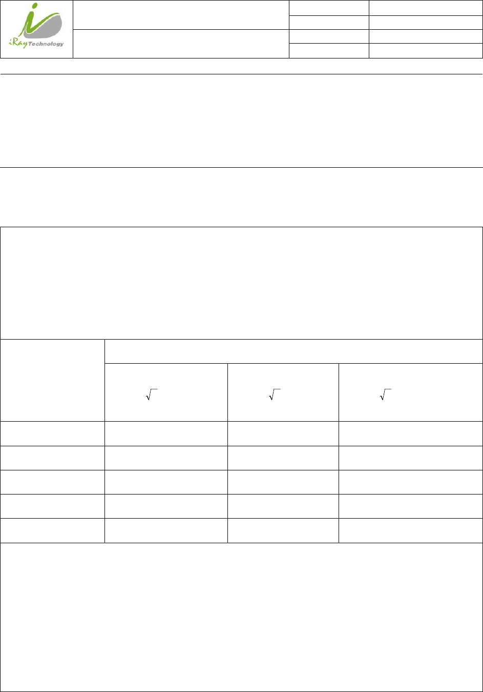
Electromagnetic immunity
Mars1717V is intended for use in the electromagnetic environment specified below. The customer or the
user of Mars1717V should assure that it is used in such an environment.
Immunity Test IEC 60601 Test
Level Compliance Level Electromagnetic Environment - Guidance
Electrostatic discharge
(ESD)
IEC 61000-4-2
±6 kV contact
±8 kV air
±6 kV contact
±8kV air
Floors should be wood, concrete or ceramic tile. If
floors are covered with synthetic material, the relative
humidity should be at least 30%.
Electrical fast
transient/ burst
IEC 61000-4-4
±2 kV for power
supply lines
±1 kV for input/
output lines
±2 kV for power
supply lines
±1 kV for input/
output lines
Mains power quality should be that of a typical
commercial or hospital environment.
Surge
IEC 61000-4-5
±1 kV differential
mode
±2 kV common
mode
±1 kV differential
mode
±2 kV common
mode
Mains power quality should be that of a typical
commercial or hospital environment.
Voltage dips, short
interruptions and
voltage variations on
power supply input
lines
IEC 61000-4-11
<5% UT (>95%
dip in UT) for 0.5
cycle.
40% UT (60% dip
in UT) for 5 cycle.
70% UT (30% dip
in UT) for 25
cycle.
<5% UT (>95%
dip in UT) for 5
sec.
<5% UT (>95%
dip in UT) for 0.5
cycle.
40% UT (60% dip
in UT) for 5 cycle.
70% UT (30% dip
in UT) for 25
cycle.
<5% UT (>95%
dip in UT) for 5
sec.
Mains power quality should be that of a typical
commercial or hospital environment. If the user of that
requires continued operation during power supply
interruptions, it is recommended that be powered from
an uninterruptible power supply.
Power frequency
(50/60Hz) magnetic
field
IEC 61000-4-8
3 A/m 3 A/m
Power frequency magnetic fields should be at levels
characteristic of a typical location in a typical
commercial or hospital environment.
UT is the a.c. mains voltage prior to application of the test level.
Guidance and manufacturer’s declaration----electromagnetic immunity
iRay Technology (Shanghai) Ltd. Doc N0. 037‐201‐02
Version A1
Mars1717VUser’sManual Date 2015.11.06
Page 121/141
Page 121
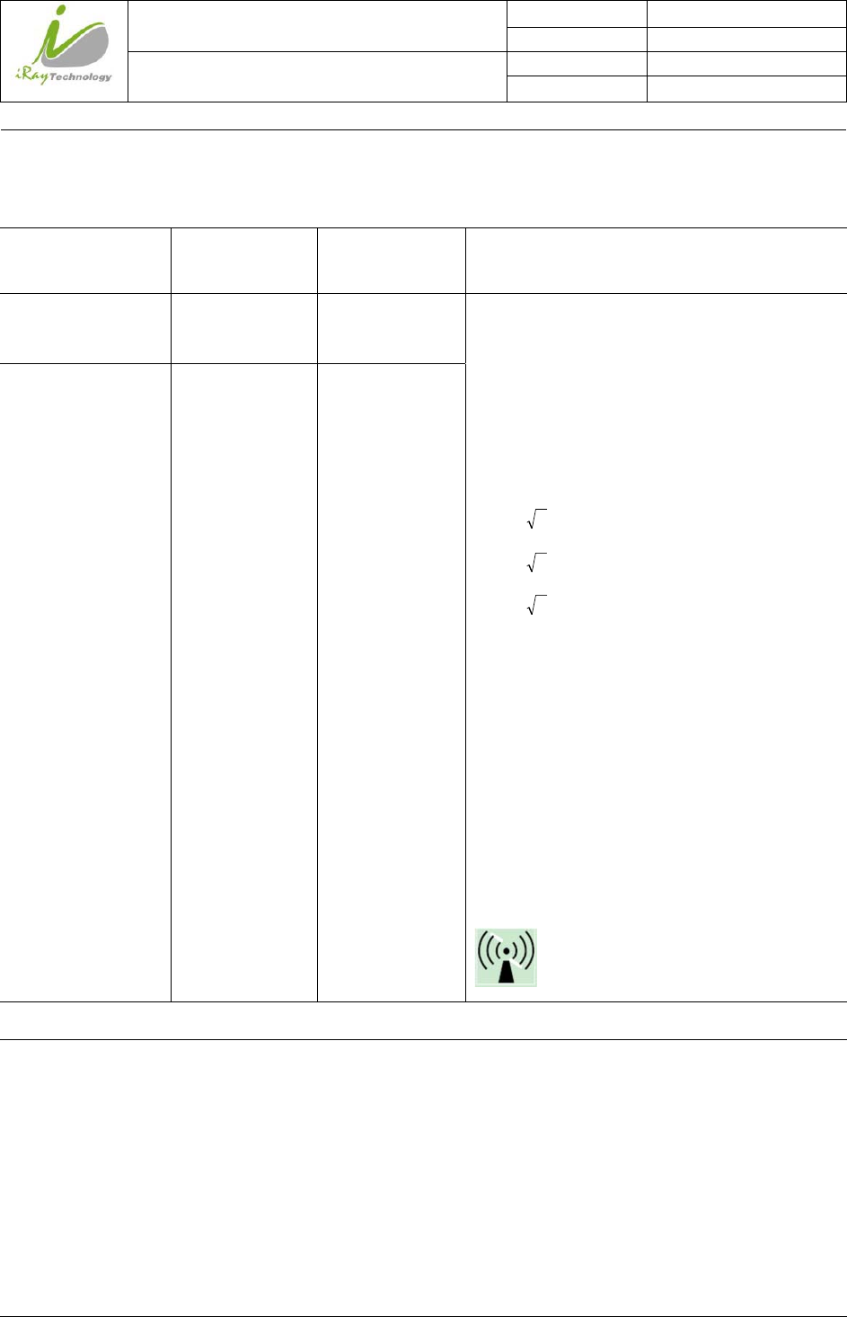
Mars1717V is intended for use in the electromagnetic environment specified below. The customer or the
user of Mars1717V should assure that it is used in such an environment.
Immunity Test IEC 60601 Test
Level Compliance Level Electromagnetic Environment - Guidance
Conducted RF
IEC 61000-4-6
3 Vrms
150kHz to 80MHz
3 Vrms
Portable and mobile RF communications equipment,
AC-DC adapter or electromagnet should be used not
closer to any part of the Model Mars1717V, including
cables, than the recommended separation distance
calculated from the equation applicable to the
frequency of the transmitter.
Recommended separation distance
d = 1,2
p
d = 1,2 80 MHz to 800 MHz
d = 2,3
p
800 MHz to 2,5 GHz
Where P is the maximum output power rating of the
transmitter in watts (W) according to the transmitter
manufacturer and d is the recommended separation
distance in meters (m).
Field strengths from fixed RF transmitters, as
determined by an electromagnetic site survey, should
be less than the compliance level in each frequency
range.
Interference may occur in the vicinity of equipment
marked with the following symbol:
Radiated RF
IEC 61000-4-3
3 V/m
80MHz to 2.5GHz
3 V/m
NOTE: UT is the a.c. mains voltage prior to application of the test level.
NOTE1 At 80 MHz and 800 MHz, the higher frequency range applies.
NOTE2 These guidelines may not apply in all situations. Electromagnetic propagation is affected by
absorption and reflection from structures, objects and people.
a. Field strengths from fixed transmitters, such as base stations for radio (cellular/cordless) telephones and
land mobile radios, amateur radio, AM and FM radio broadcast and TV broadcast cannot be predicted
theoretically with accuracy. To assess the electromagnetic environment due to fixed RF transmitters, an
electromagnetic site survey should be considered. If the measured field strength in the location in which
p
iRay Technology (Shanghai) Ltd. Doc N0. 037‐201‐02
Version A1
Mars1717VUser’sManual Date 2015.11.06
Page 122/141
Page 122
Mars1717V is used exceeds the applicable RF compliance level above, Mars1717V should be observed to
verify normal operation. If abnormal performance is observed, additional measures may be necessary, such
as re-orienting or relocating Mars1717V.
b. Over the frequency range 150 kHz to 80 MHz, field strengths should be less than [V1] V/m.
Recommended separation distances between portable or mobile RF communications equipment and
Mars1717V
Mars1717V is intended for use in an electromagnetic environment in which radiated RF disturbances are
controlled. The customer or user of Mars1717V can help prevent electromagnetic interference by
maintaining a minimum distance between portable or mobile RF communications equipment (transmitters)
and Mars1717V as recommended below, according to the maximum output power of the communications
equipment.
Rated maximum
output
power of transmitter
/W
Separation distance according to frequency of transmitter /m
150kHz~80 MHz
d = 1.2 p
80 MHz~800 MHz
d = 1.2 p
800 MHz ~2.5GHz
d = 2.3 p
0.01 0.12 0.12 0.23
0.1 0.38 0.38 0.73
1 1.2 1.2 2.3
10 3.8 3.8 7.3
100 12 12 23
For transmitters rated at a maximum output power not listed above, the recommended separation distance d
inmeters (m) can be estimated using the equation applicable to the frequency of the transmitter, where P is
the maximum output power rating of the transmitter in watts (W) according to the transmitter manufacturer.
NOTE 1 At 80 MHz and 800 MHz, the separation distance for the higher frequency range applies.
NOTE 2 These guidelines may not apply in all situations. Electromagnetic propagation is affected by
absorption and reflection from structures, objects and people.
Cables information belowis provided for EMC reference.

iRay Technology (Shanghai) Ltd. Doc N0. 037‐201‐02
Version A1
Mars1717VUser’sManual Date 2015.11.06
Page 123/141
Page 123
Cable
Recommended
cable length
Shielded or Unshielded Number Cable classification
Input Power Cable 3m Unshielded 1 Set AC Power
Ethernet Cable 3.5m Shielded 1 pcs Signal
DC Power Cable 3.5m Unshielded 1 pcs Signal
LAN Cable 3m Shielded 1 pcs Signal
Important information regarding Electro Magnetic Compatibility (EMC)
Mars1717V require special precautions regarding EMC and needs to be installed only by iRay or authorized
personnel and put into service according to EMC information provided in the user manual. Mars1717V in
use may be susceptible to electromagnetic interference from portable and mobile RF communications such
as mobile (cellular) telephones. Electromagnetic interference may result in incorrect operation of the system
and create a potentially unsafe situation.
Mars1717V conforms to this EN60601-1-2:2007 standard for both immunity and emissions.
Nevertheless, special precautions need to be observed:
The use of accessories, transmitters and cables other than those specified by this User Manual, with the
exception of accessories and cables sold by iRay of Mars1717V as replacement parts for internal
components, may result in increased EMISSIONS or decreased IMMUNITY of Mars1717V.
Mars1717V should not be used adjacent to or stacked with other equipment.
5.3 Radio Frequency Compliance Information
Country Item
U.S.A FCC Part 15.107 Subpart (b) / 15.109(g) Subpart B
FCC Part 15 Subpart E 15.407
FCC Part 15 Subpart C 15.247

iRay Technology (Shanghai) Ltd. Doc N0. 037‐201‐02
Version A1
Mars1717VUser’sManual Date 2015.11.06
Page 124/141
Page 124
European Union ETSI EN 301 489-1 V1.8.1 (EMC)
ETSI EN 301 489-17 V2.1.1 (EMC)
EN 300 328 V.1.7.1; EN 301 893 V1.6.1 (RF)
EN 62311:2008 (RF Exposure)
ETSI EN 300 328 V1.7.1; EN 301 893, V1.5.1 (Radio Spectrum)
5.3.1 FCC Compliance
This equipment has been tested and found to comply with the limits for a Class B digital device,
pursuant to part 15 of FCC Rules. These limits are designed to provide reasonable protection against
harmful interference in a residential installation.
Operation is subject to the following tow conditions.
This device may not cause harmful interference.
This device must accept any interference received, including interference that may cause undesired
operation.
This equipment generates, uses, and can radiate radio frequency energy and, if not installed and used in
accordance with the instruction, may cause harmful interference to radio communications. However,
there is no guarantee that interference will not occur in a particular installation. If this equipment does
cause harmful interference to radio or television reception, which can be determined by turning the
equipment off and on, the user is encouraged to try to correct the interference by one or more of the
following measure.
Reorient or relocate the receiving antenna.
Increase the separation between the equipment and receiver.
Connect the equipment into an outlet on a circuit different from that to which the receiver is
connected.
Consult the distributor or an experienced radio/TV technician for help.
5.4 Battery Safety Standards
Standards Description
UL1642 Component Recognition on the Secondary Li-ion cell
iRay Technology (Shanghai) Ltd. Doc N0. 037‐201‐02
Version A1
Mars1717VUser’sManual Date 2015.11.06
Page 125/141
Page 125
UL 2054:2004 R9.11 Household and commercial Batteries
IEC 62133:2012 Secondary cells and batteries containing alkaline or other non-acid
electrolytes
UN38.3 United Nations Recommendations on the Transport of dangerous
goods Manual of tests and Criteria
ST/SG/AC.10/11/Rev.5/Amend.1&Amend.2
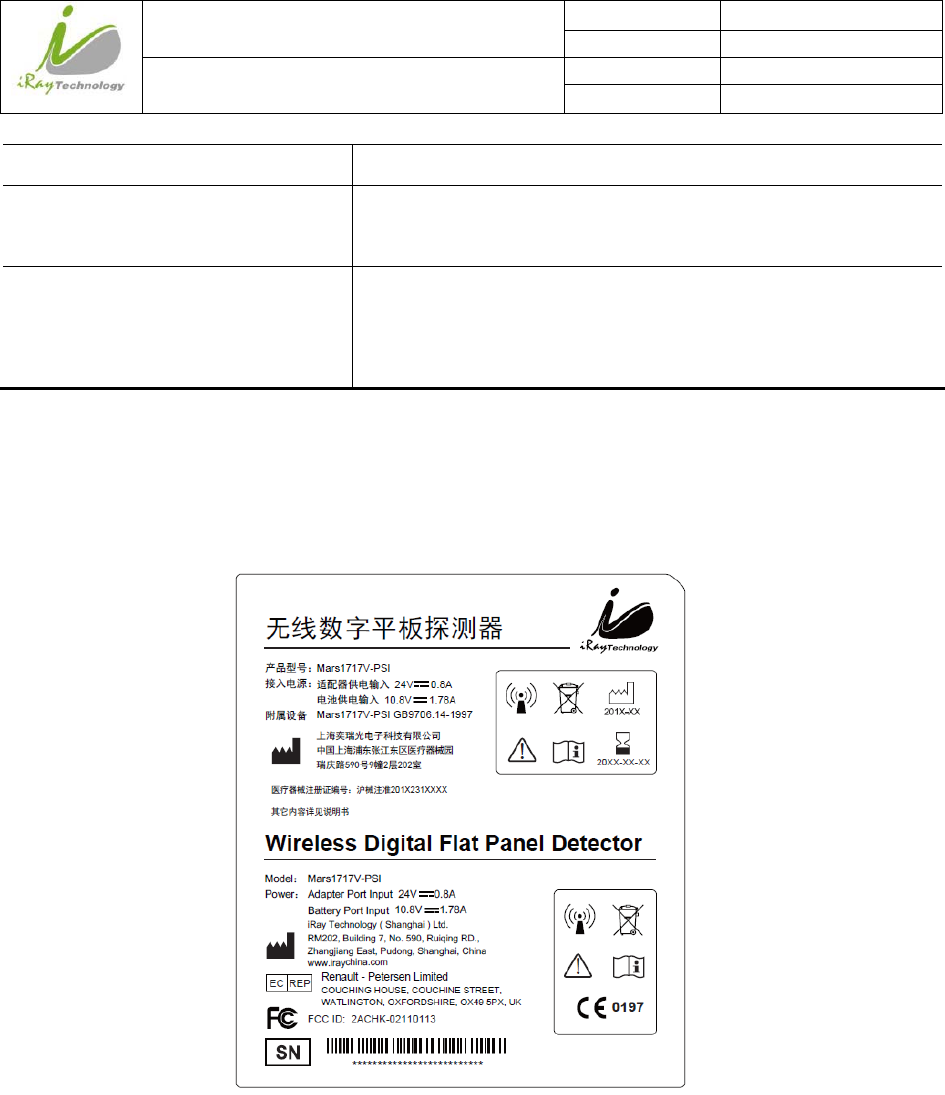
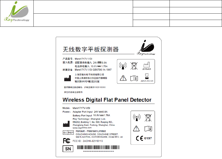
5.5 Product Label
5.5.1 Detector
Mars1717V-PSI detector
Mars1717V-VSI detector
iRay Technology (Shanghai) Ltd. Doc N0. 037‐201‐02
Version A1
Mars1717VUser’sManual Date 2015.11.06
Page 126/141
Page 126
iRay Technology (Shanghai) Ltd. Doc N0. 037‐201‐02
Version A1
Mars1717VUser’sManual Date 2015.11.06
Page 127/141
Page 127
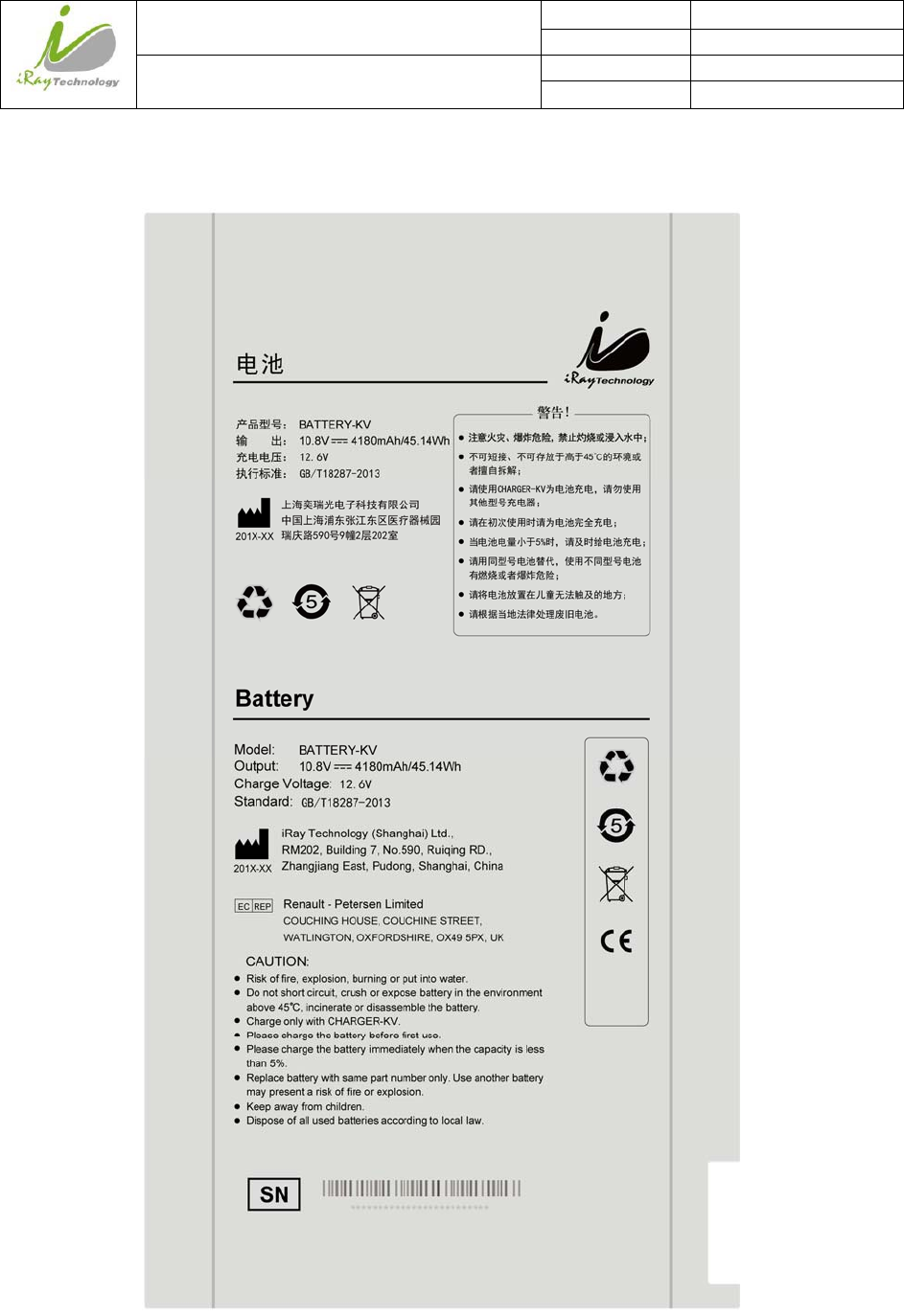
5.5.2 Battery
iRay Technology (Shanghai) Ltd. Doc N0. 037‐201‐02
Version A1
Mars1717VUser’sManual Date 2015.11.06
Page 128/141
Page 128
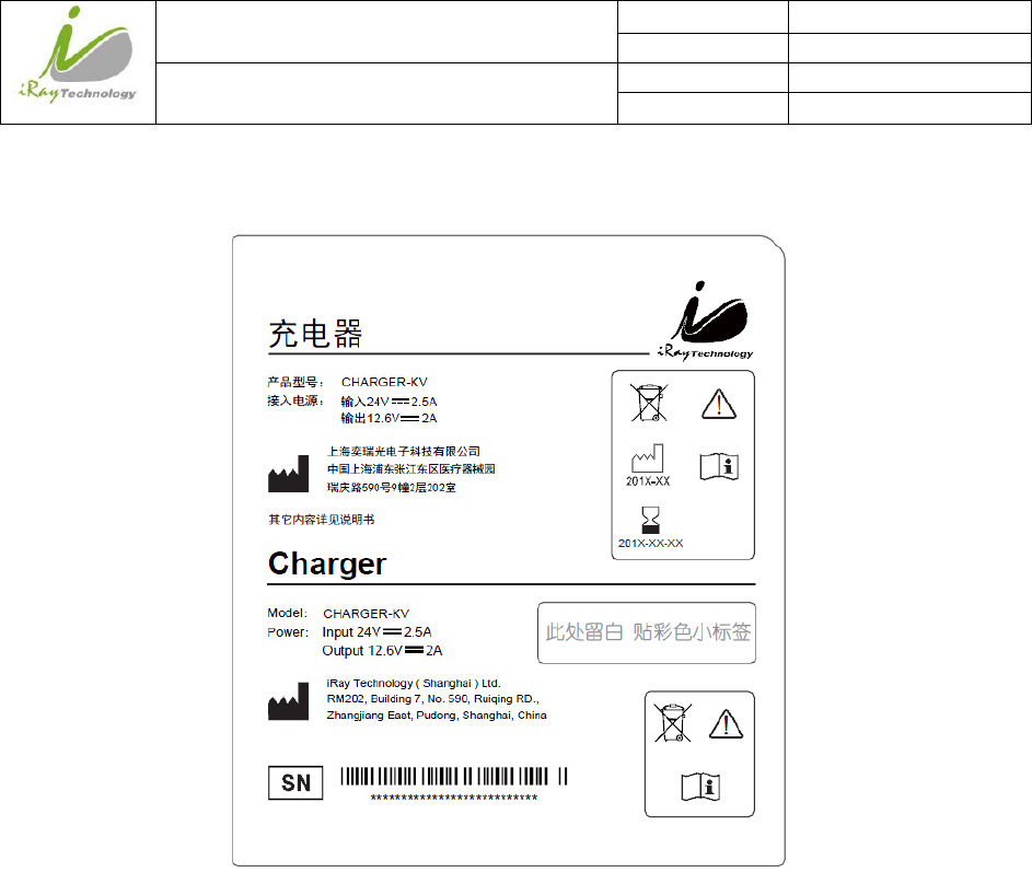
5.5.3 Battery Charger
iRay Technology (Shanghai) Ltd. Doc N0. 037‐201‐02
Version A1
Mars1717VUser’sManual Date 2015.11.06
Page 129/141
Page 129
6 Trouble Shooting
When user encounters problems or error messages, refer to this chapter. If the problem persists, turn off the panel
and contact iRay service department (service@iraychina.com). We would provide the best service.
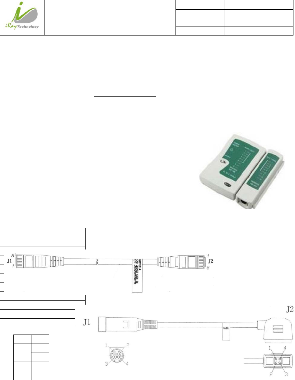
6.1 Cable Inspection
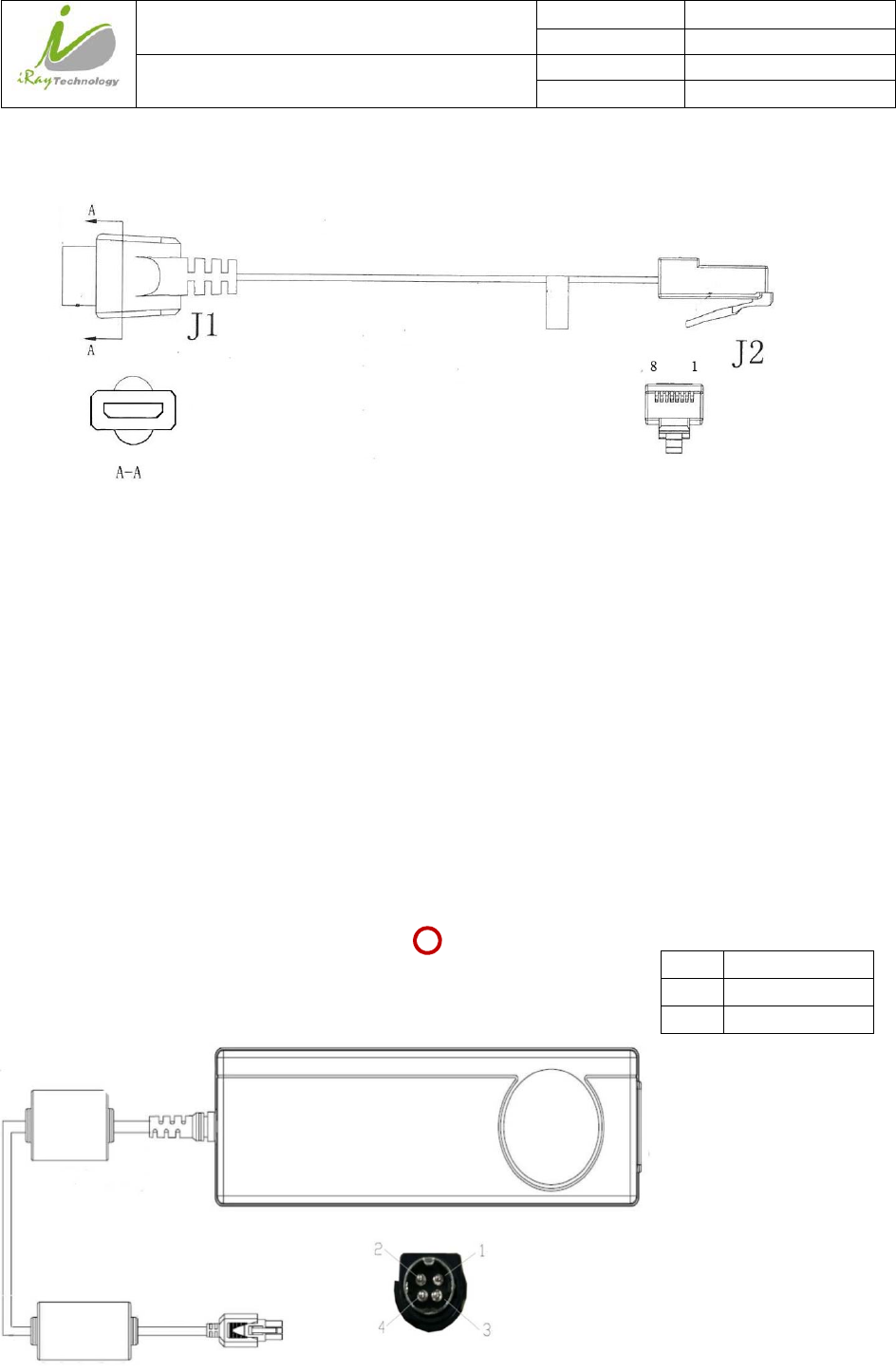
6.1.1 Ethernet cable
6.1.1.1 Inspection method
Test the Ethernet cable detector by cable tester, and confirm whether all the
cores of the cable are conductive. If the cable tester is not available, please
check the definition of Ethernet cable and test the conductive between each
pin of connector.
6.1.1.2 Definition of Ethernet cable
6.1.1.3 Charge cable
inspection
Measure the conductive between each pin of J1 and J2 by multimeter.
Colour J1 J2
Orange\White 1 3
Orange 2 6
Green\White 3 1
Blue 4 7
Blue\White 5 8
Green 6 2
Brown\White 7 4
Brown 8 5
Grounding wire Shell Shell
J1 J2
3 1
3
2 2
4
iRay Technology (Shanghai) Ltd. Doc N0. 037‐201‐02
Version A1
Mars1717VUser’sManual Date 2015.11.06
Page 130/141
Page 130
6.1.2 Date cable inspection
According to the definition of data cable to verify the conductive between each pin of J1 and J2 by multimeter if
there is only one data cable in the field.
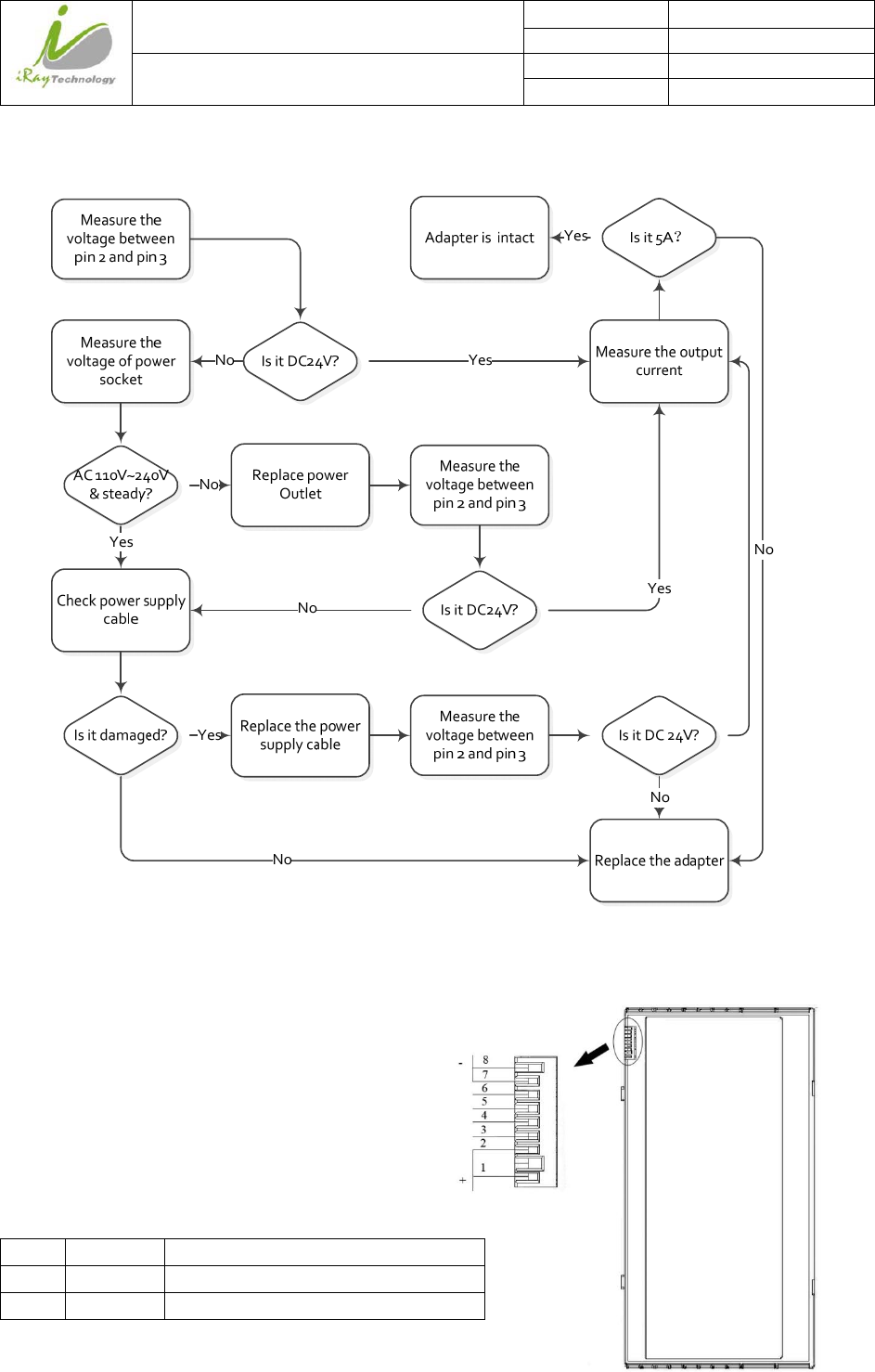
6.2 Adapter Inspection
6.2.1 Adapter connector definition
Pin Description
2 DC +24V/5.0A
3 0V
iRay Technology (Shanghai) Ltd. Doc N0. 037‐201‐02
Version A1
Mars1717VUser’sManual Date 2015.11.06
Page 131/141
Page 131
6.2.2 Inspection method
Connect the adapter to the detector or charging dock to confirm whether the battery is in working order if
verifying the output current is not practicable.
6.3 Battery Inspection
6.3.1 Battery pin definition
Pin Symbol Description
1,2 P+ Battery Discharge Positive Terminal
7,8 P- Battery Discharge Negative Terminal
iRay Technology (Shanghai) Ltd. Doc N0. 037‐201‐02
Version A1
Mars1717VUser’sManual Date 2015.11.06
Page 132/141
Page 132
6.3.2 Inspect Method
Measurethe
voltagebetween
thePin1,2andPin
7,8
BatteryisinfactVoltageLessthan9v About10.V
Chargethebatteryviadock
in30minutes.Charging
timewillbelongerwhile
chargingviadetector
Measurethe
voltagebetween
thePin1,2andPin
7,8
VoltageLessthan9v About10.VReplacebattery
The battery is expendable and its life is shortened through use. Recycle the battery if the fully charged battery only
last not more than 1 hour. Wasted batteries suggested return to manufacturer or put at appointed public battery
reclaim area, do not mix battery with other waste or dispose of battery ad libitum.
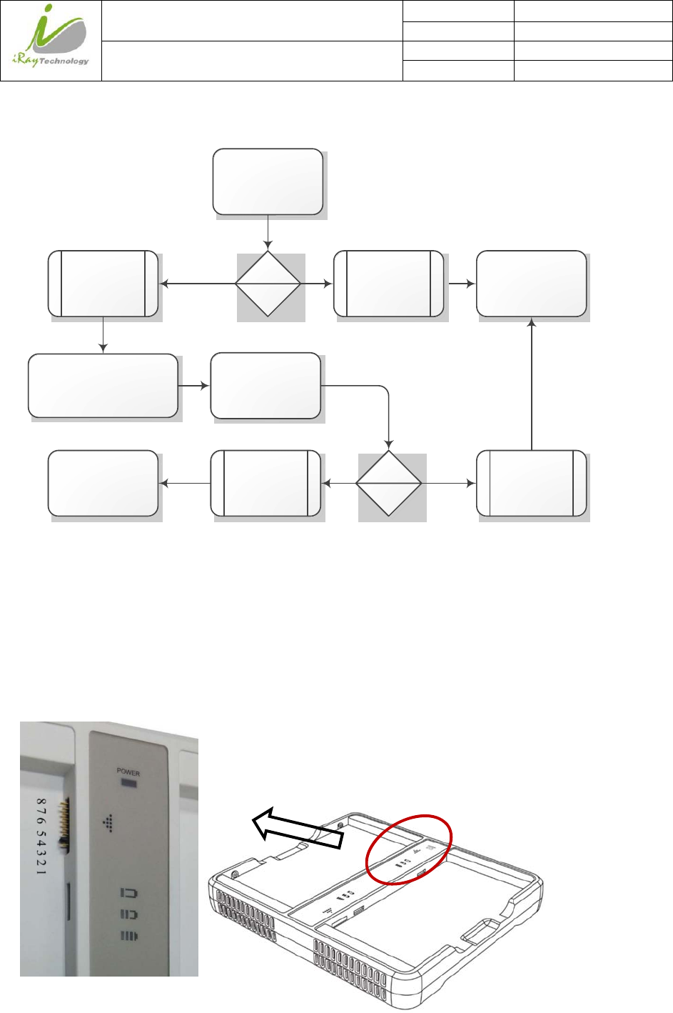
6.4 Dock Inspection
6.4.1 Dock pin definition
iRay Technology (Shanghai) Ltd. Doc N0. 037‐201‐02
Version A1
Mars1717VUser’sManual Date 2015.11.06
Page 133/141
Page 133
6.4.2 Inspection method
1.Doespower
indicatorlight
up?
AdapterinspectionNo Adapterworks
normally?
ReplaceAdapeter
No
Measurethe
voltagebetween
pin1andpin8
Yes
Yes
Insertthebattry Doescharging
indicatorlightup? No
Dockisintact
Yes
BatteryinspectionDoesbatterywork
normally?
Replacebattery
No
Isit找研发要V?
Dockfault
No
IndicatorfaultYes
Yes
6.5 Detector Main Unit Inspection
Know how to obtain the log of SDK and detector is necessary before diagnose any problem of detector main unit,
and the method is described in chapter 6.1.
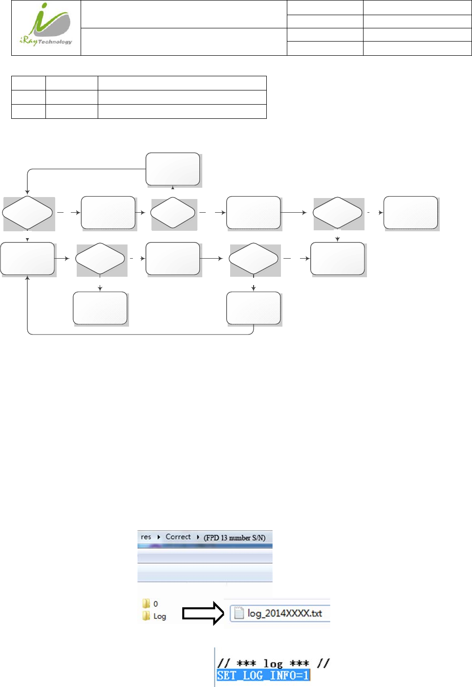
6.5.1 Get SDK and detector log
6.5.1.1 Fetch SDK log
Find the location of iDemo.exe, and there is a folder called “Correct” in the same directory. Find the folder named
by the serial number of detector. The folder called “Log” is the storage path of SDK fie, and the date is contained
in name of each log file. Please compress the log file before send it.
The log function can be switched on in the config.ini. in the folder named “Res”, please check the configuration
before start iDemo.
SET_LOG_INFO=1//Open log function’
SET_LOG_INFO=0//Close log function
Pin Voltage Description
1,2 + Battery Charge Positive Terminal
7,8 - Battery Charge Negative Terminal
iRay Technology (Shanghai) Ltd. Doc N0. 037‐201‐02
Version A1
Mars1717VUser’sManual Date 2015.11.06
Page 134/141
Page 134
6.5.1.2 Detector log
Find FTP Server.exe and open the FTP Server, attention that the FTP port number should
be set as same as the config.ini of iDemo. Click button to start FTP server after finish setting the FTP port
number.
Find the “L” button in the following diagram in the configuration GUI of iDemo, click “L” button and the FTP
will upload the “Log” in the storage path “upload\[FPD 13 number S/N]\logs” which is at the same location of
iDemo.exe.
iRay Technology (Shanghai) Ltd. Doc N0. 037‐201‐02
Version A1
Mars1717VUser’sManual Date 2015.11.06
Page 135/141
Page 135
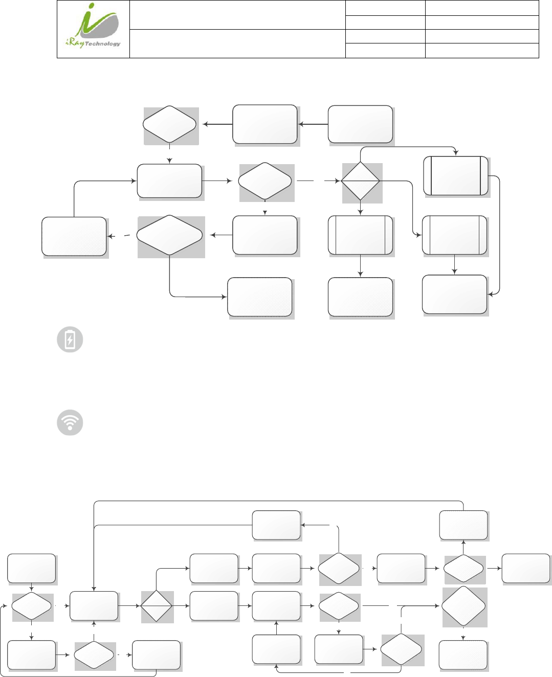
6.6 Power up failure inspection
Plugin charge cable Yes
Failtopowerup
Canpowerup
theFPD?
Adapter&charging
cableinspection
No
Power
indicator
status
Indicator
remainsgreen
Flashgreen &
remaingreen
inalongtime
Flashorange&
remaingreen
inalong time
Replacebatteryand
chargeit
Batteryfailure
DoesAdapterand
chargingcablework
properly?
Replacethe
damagepart No
Returndetectorto
factory
Yes
Presspowbutton
morethan8secs.
Canpowerup
theFPD?
No
is the label of power indicator. Skip the step “Press reset button” if no reset button, because the previous
version doesn’t content press button, and it’s no effect in normal use.
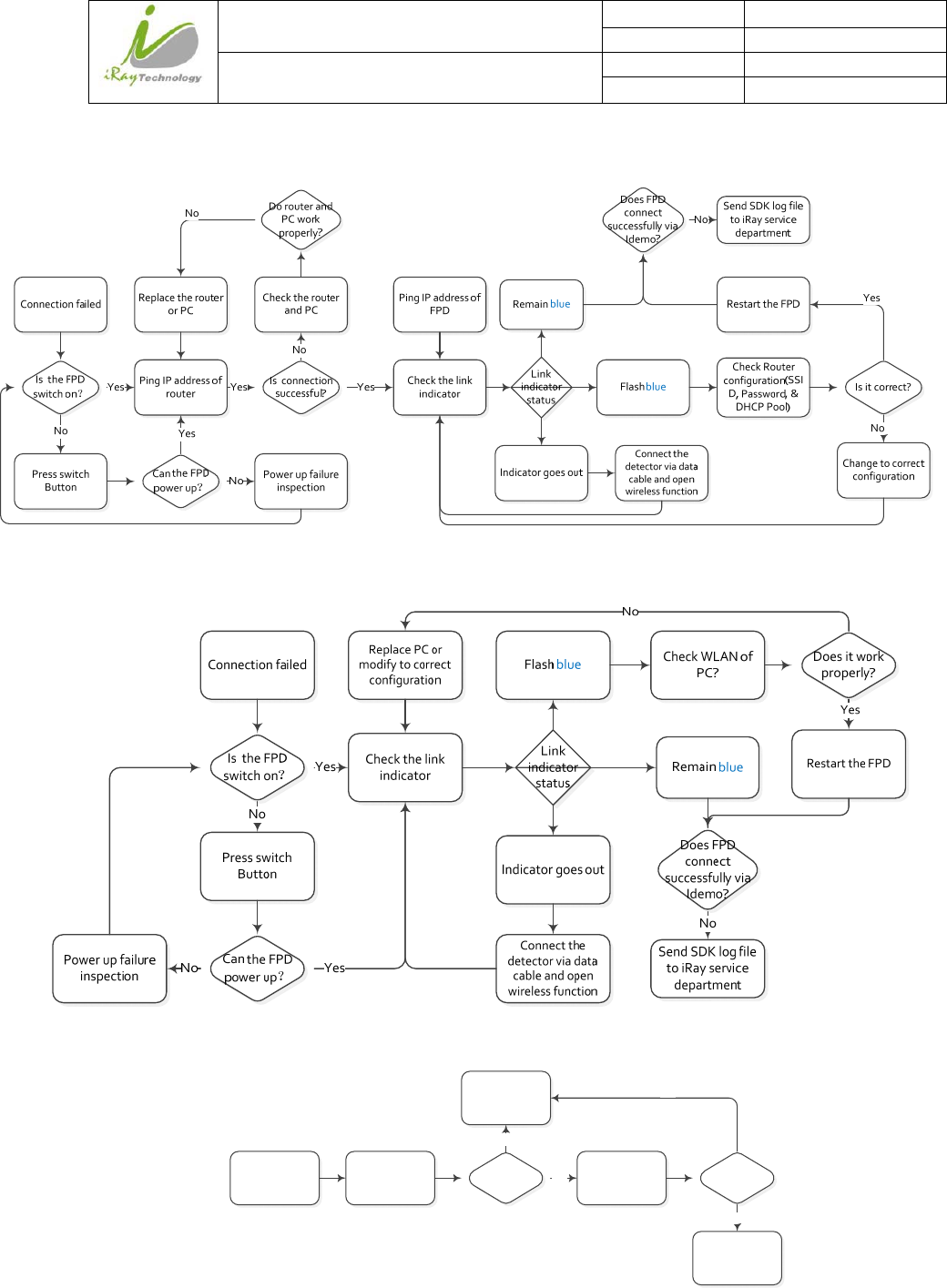
6.7 Connection inspection
is label of link indicator. If there is connection error from iRayDR, please view the FAQ of iRay before
checking the connection issue through iDemo
6.7.1 Connection failed in wired mode
Checkthelink
indicator
IstheFPD
switchon?Yes
Pressswitch
Button
No
Can theFPD
p0werup?
Yes
Powerupfailure
inspection
No
Flashblue
Link
indicator
status
Remaingreen
Checkthe
Ethernetcardof
PC
Replacepcor
Ethernetcardor
PC
DoesEthernet
cardworks
properly?
Datacable
inspection
Yes Datacableis
infact
No Replacedatacable
ReturnFPDto
factoray
PingIPaddressof
detector
DoesFPD
connect
successfullyvia
Idemo?
ChecktheIP
addressofPC
No
Isitonthe
samesegment
OfFPDIP?
Yes
ModifyPCIP
address
No
DoesFPD
connect
successfullyvia
Idemo?
SendSDKlogfile
toiRayservice
department
Yes
No
Connectionfailed
iRay Technology (Shanghai) Ltd. Doc N0. 037‐201‐02
Version A1
Mars1717VUser’sManual Date 2015.11.06
Page 136/141
Page 136
6.7.2 Connection Failed in Client Mode
6.7.3 Disconnect in AP Mode
6.8 DarkImageAcquisitionAfterExposureinInnerMode
Modifythetrigger
methodto
“Software”
Acquireabright
imageIsitdarkimage?
ReturnFPDto
factory
No
ChecktheX‐ray
machine
Yes DoesproduceX‐
ray?
Yes
MaintainX‐ray
machine
No
iRay Technology (Shanghai) Ltd. Doc N0. 037‐201‐02
Version A1
Mars1717VUser’sManual Date 2015.11.06
Page 137/141
Page 137
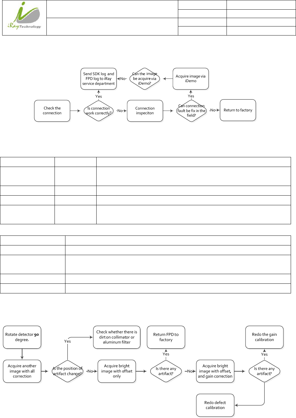
6.9 No Image Acquire after Exposure
6.10 Image Inspection
All the correction files are in the storage path “res\Correct\ [FPD series number] \0”
Calibration type File format Remark
Offset *.off iRay mostly use post offset, the offset is done during the image acquisition process.
So the offset file is not effective in the correction file storage path.
Gain *.gn The gain file can be select or deselect through iDemo
Defect *.dft The gain file can be select or deselect through iDemo
Lag *.lag The Most gain is effective while it’s in the correction file storage path. Rename it
or move it to other directory can make it invalid.
The following is the image
Image type Description
Original dark image Acquire by click “Prep Acquire” button without exposure and offset correction
Dark image Acquire by click “Prep Acquire” button without exposure and the offset calibration should be
added at least.
Original bright image Acquire the image under exposure condition and without any correction.
Bright image with offset Acquire the image under exposure condition and add offset correction only.
6.10.1 Artifact on bright image
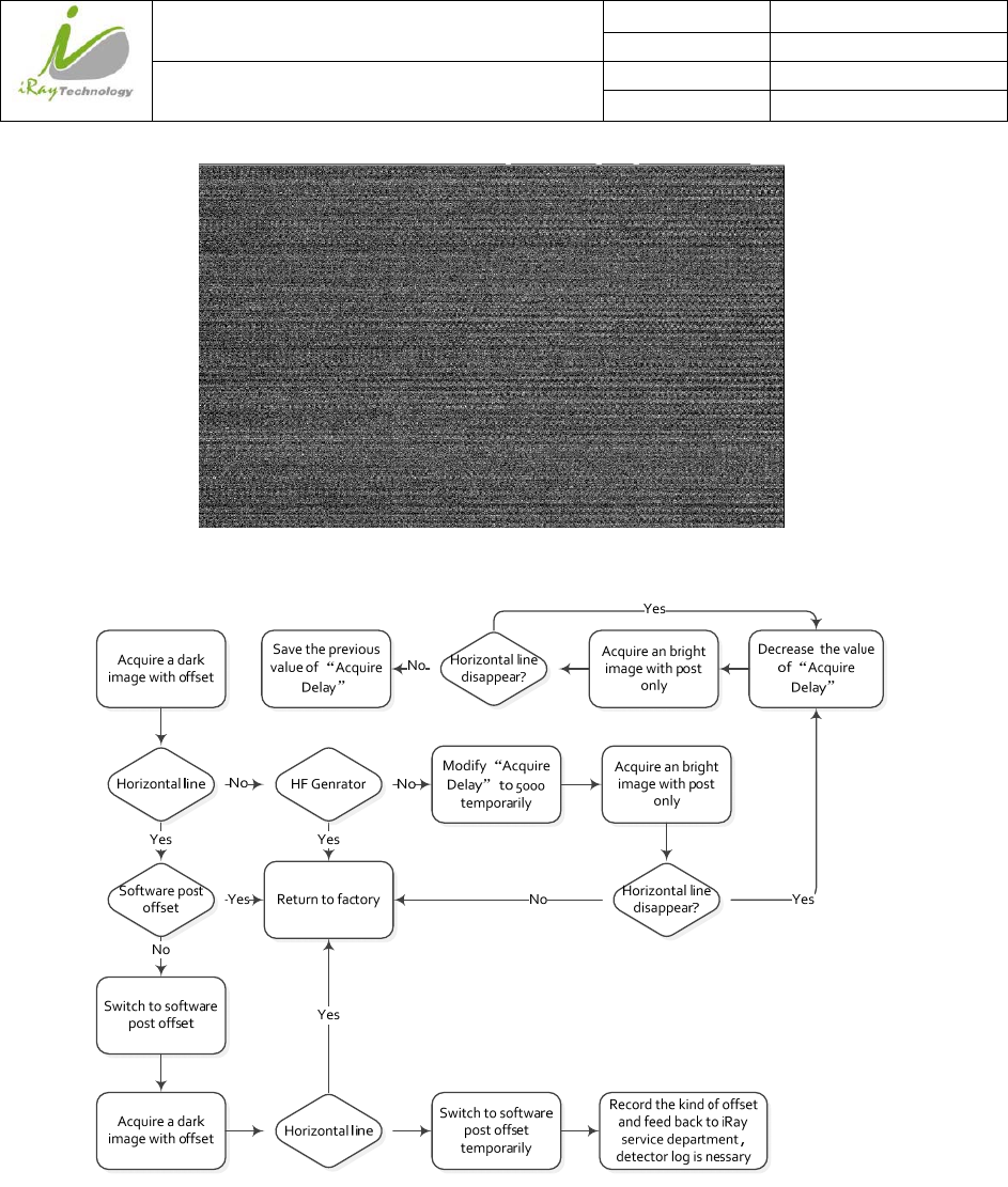
6.10.2 Horizontal Line on bright image
Adjust the WW to 30 and WL to 100 through iDemo for checking the horizontal line of dark image. Normally the
dark image with horizontal line is shown as the figure 1.
iRay Technology (Shanghai) Ltd. Doc N0. 037‐201‐02
Version A1
Mars1717VUser’sManual Date 2015.11.06
Page 138/141
Page 138
Inspection method
iRay Technology (Shanghai) Ltd. Doc N0. 037‐201‐02
Version A1
Mars1717VUser’sManual Date 2015.11.06
Page 139/141
Page 139
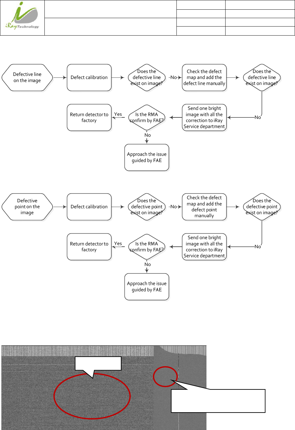
6.10.3 Defective line
6.10.4 Defective point
6.10.5 TFT broken
Acquire a dark image, if one part of the image is much smooth than the normal dark image. The TFT must be
broken by intense impact.
N
ormal area
Abnormal region of image, it is
smooth
and less
grainy

iRay Technology (Shanghai) Ltd. Doc N0. 037‐201‐02
Version A0
Mars1717VUser’sManual Date 2015.08.26
Page 140/141
Page 140
7 ServiceInformation
7.1 Product lifetime
The estimated product lifetime is up to 10 years under appropriate regular inspection and maintenance.
7.2 Regular inspection and Maintenance
In order to ensure the safety of patients, operating person and third parties, and to maintain the performance and
reliability of the equipment, be sure to perform regular inspection at least once a year. If necessary, clean up the
equipment, make adjustments, or replace consumables such as fuses, detector cable, etc. There may be cases
where overhaul is recommended depending on conditions. Contact iRay service office or local iRay dealer for
regular inspection or maintenance.
There is a Ni-MH battery in the FPD, its lifetime is 5 years, when arrived in the lifetime of the battery is need to
be placed. And the placement need contact Shanghai Iray after-sales service departments or authorized product
distributors.

iRay Technology (Shanghai) Ltd. Doc N0. 037‐201‐02
Version A0
Mars1717VUser’sManual Date 2015.08.26
Page 141/141
Page 141
7.3 Repair
If a problem cannot be solved even taking the measures indicated in troubleshooting, contact your sales
representative or local iRay dealer for repairs. Please refer to the name label and provide the following
information:
Product Name:
Series Number:
Description of Problem: as clearly as possible.
7.4 Replacement parts support
Performance parts (parts required to maintain the function of the product) of this product will be stocked for 5
years after discontinuance of production, to allow for repair.