IRay Technology 02110113 Wireless Digital Flat Panel Detector User Manual 1
iRay Technology (Shanghai) Ltd. Wireless Digital Flat Panel Detector Users Manual 1
Contents
- 1. User manual
- 2. Users Manual-1
- 3. Users Manual-2
Users Manual-1
iRay Technology (Shanghai) Ltd. Doc N0. 037‐201‐02
Version A1
Mars1717VUser’sManual Date 2015.11.06
Page 1/141
1
Mars1717V User’s Manual
Authors : Dong Zhu
Doc. No. : 037-201-02
Date : 2015.11.06
Version : A1
Status : Released
Project : Mars1717V /037

iRay Technology (Shanghai) Ltd. Doc N0. 037‐201‐02
Version A1
Mars1717VUser’sManual Date 2015.11.06
Page 2/141
Page 2
Author Dong Zhu Inspector Yimin Huang
Approver Zhiqiang Fang
Verified Record
Department Name Signature Date Department Name Signature Date
Quality Wei PAN
Test-verification Long Yu
Pre-production Yong WANG
Marketing Yao LU
Product Lin Liu
Delivery Department
Department Department Department Department Department Others
Document History
Ver. Date
Revised
by
Checked
by
Approved
by
Description
A0 2015.08.26 Dong Zhu Yimin.Huang Zhiqiang Fang First Released
A1 2015.11.06 Dong Zhu Yimin.Huang Zhiqiang Fang
Update the
information to the
customers about
FCC
iRay Technology (Shanghai) Ltd. Doc N0. 037‐201‐02
Version A1
Mars1717VUser’sManual Date 2015.11.06
Page 3/141
Page 3
To Customers
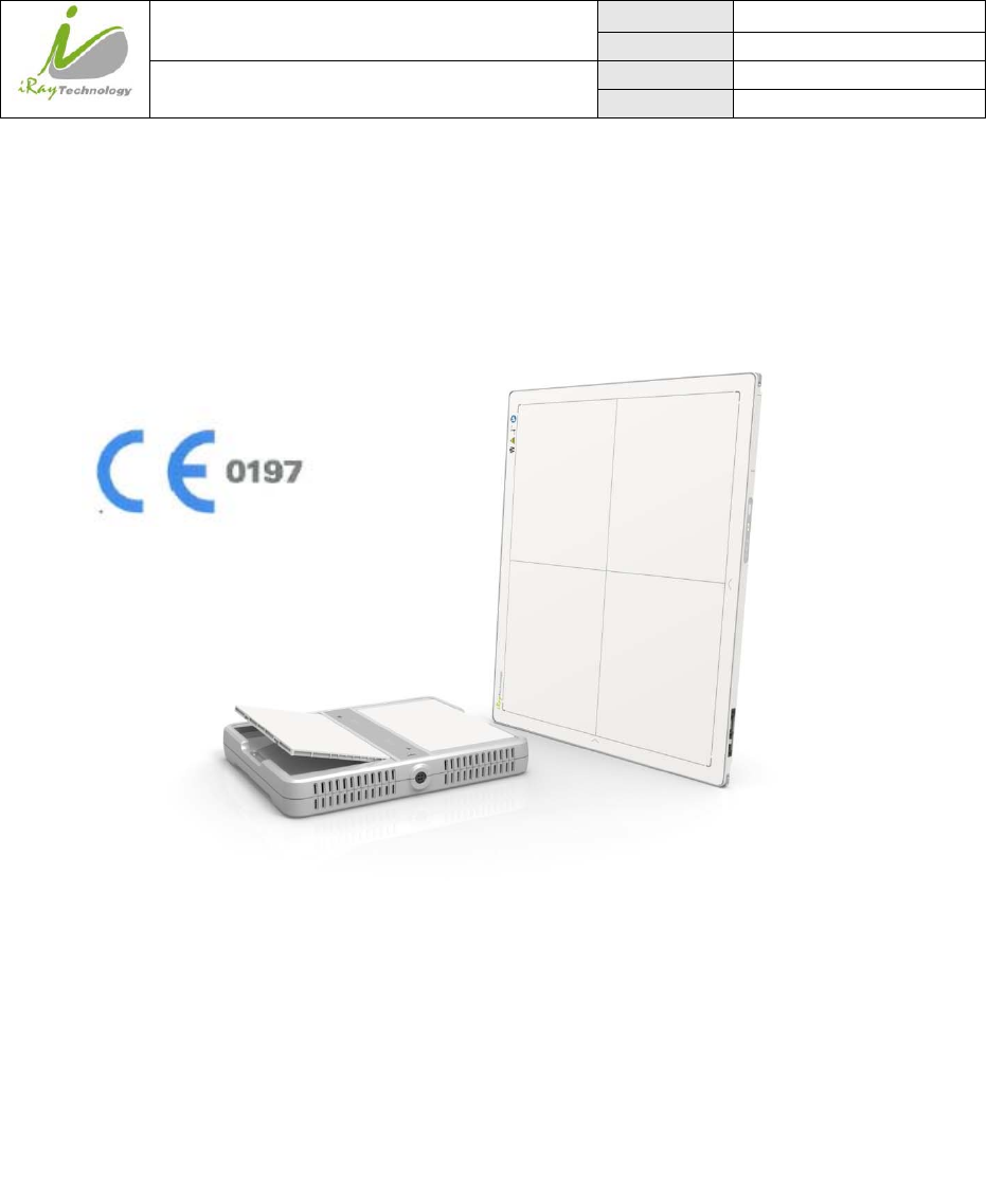
Congratulations on your purchase of the Mars1717V Wireless Digital Flat Panel
(hereinafter referred to as Mars1717V) which is manufactured by iRay Technology (Shanghai)
Ltd. (hereinafter referred to as iRay).
At iRay, we strive to not only make the world-class products that deliver the best value possible
to our customers but also offer the highest quality of service and customer care. Please take time
to read through this user guide in order to utilize the product effectively. We hope you enjoy the
experience with iRay Mars1717V.
If you have any questions or suggestions, please feel free to contact us.
About FCC
FCC Compliance
This device complies with Part 15 of the FCC Rules. Operation is subject to the following two conditions:
(1) This device may not cause harmful interference;
(2) This device must accept any interference received, including interference that may cause undesired operation.
Caution: Any changes or modifications not expressly approved by the party responsible for compliance
could void the user's authority to operate this equipment.
NOTE: This equipment has been tested and found to comply with the limits for a Class B digital device,
pursuant to Part 15 of the FCC Rules. These limits are designed to provide reasonable protection against
harmful interference in a residential installation. This equipment generates, uses and can radiate radio
frequency energy and, if not installed and used in accordance with the instructions, may cause harmful
interference to radio communications. However, there is no guarantee that interference will not occur in
a particular installation. If this equipment does cause harmful interference to radio or television reception,
which can be determined by turning the equipment off and on, the user is encouraged to try to correct the
interference by one or more of the following measures:
Reorient or relocate the receiving antenna.
Increase the separation between the equipment and receiver.
Connect the equipment into an outlet on a circuit different from that to which the receiver is
connected.
Service Office
Tel: +86 21 50720560 - 8059
Fax: +86 21 50720561
E-mail: service@iraychina.com
Location: 2F, Building 7, No.590, Ruiqing Rd, Pudong, Shanghai, China PC: 201201
iRay Technology (Shanghai) Ltd. Doc N0. 037‐201‐02
Version A1
Mars1717VUser’sManual Date 2015.11.06
Page 4/141
Page 4
Consult the dealer or an experienced radio/TV technician for help.
FCC requires this product to be used indoors for the frequency range 5.15 to 5.25 GHz to reduce
the potential for harmful interference to co-channel Mobile Satellite systems.
Federal Communication Commission (FCC) Radiation Exposure Statement.
This EUT is compliance with SAR for general population/uncontrolled exposure limits in ANSI/IEEE
C95.1-1999 and had been tested in accordance with the measurement methods and procedures
specified in OET Bulletin 65 Supplement C. This equipment should be installed and operated contact
with the radiator & your body.
Notes on usage and management of the equipment
Read all of the instructions in the user guide before your operation. Give particular attention to all safety
precautions.
Only a physician or a legally certified operator should use this product.
The equipment should be maintained in a safe and operable condition by maintenance personnel.
Use only computers and image display monitors complying with IEC 60601-1 or IEC 60950-1. For details,
consult our sales representative or local iRay dealer.
Use only the dedicated cables. Do not use any cables other than those supplied with this product.
Request your sales representative or local iRay dealer to install this product
Caring for your environment
This symbol indicates that this product is not to be disposed of with your residential or
commercial waste.
Recycling iRay Equipment
Please do not dispose of this product with your residential or commercial waste. Improper handling of this
type of waste could have a negative impact on health and on the environment. Some countries or regions,
such as the European Union, have set up systems to collect and recycle electrical or electronic waste items.
Contact your local authorities for information about practices established in your region. If collection
systems are not available, call iRay Customer Service for assistance.
Disclaimer
1. iRay shall not be liable to the purchaser of this product or third parties for any damage, losse, or injury
incurred by purchaser or third parties as a result of fire, earthquake, any accident, misuse or abuse of this
product.

iRay Technology (Shanghai) Ltd. Doc N0. 037‐201‐02
Version A1
Mars1717VUser’sManual Date 2015.11.06
Page 5/141
Page 5
2. iRay shall not be liable to any damage, loss, or injury arising from unauthorized modifications, repairs, or
alterations to this product or failure to strictly comply with iRay’s operating and maintenance instructions.
3. iRay shall not be liable for any damage or loss arising from the use of any options or consumable products
other than those dedicated as Original iRay Products by iRay Technology.
4. It is the responsibilities of the user/attending physicians for maintaining the privacy of image data and
providing medical care services. iRay shall not be responsible for the legality of image processing , reading
and storage nor it shall be responsible for loss of image data for any reason.
5. Information regarding specification, compositions, and appearance of this product is subject to change
without prior notice.
Copyright
All rights reserved
No part of this publication may be reproduced in any form or by any means without the written permission
of iRay. The information contained herein is designed only for use with iRay Mars1717V.
Trademarks
The iRay name and iRay logo are registered trademarks of iRay Technology (Shanghai) Ltd.
iRay Technology (Shanghai) Ltd. Doc N0. 037‐201‐02
Version A1
Mars1717VUser’sManual Date 2015.11.06
Page 6/141
Page 6
Symbols and Conventions
The following symbols and conventions are used throughout the user guide.
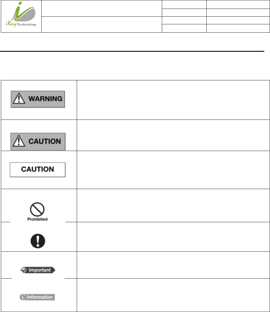
This symbol is used to identify conditions under which improper use of the
product may cause death or serious personal injury.
This notice is used to identify conditions under which improper use of the
product may cause minor personal injury.
This notice is used to identify conditions under which improper use of the
product may cause property damage.
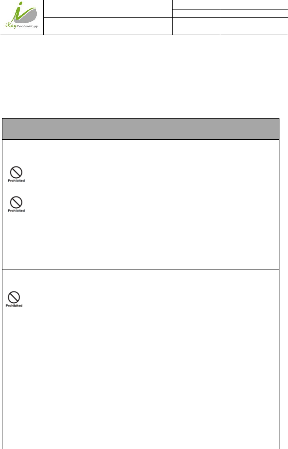
This is used to indicate a prohibited operation.
This is used to indicate an action that must be performed.
This is used to indicate important operations and restrictions.
This is used to indicate operations for reference and complementary
information.
iRay Technology (Shanghai) Ltd. Doc N0. 037‐201‐02
Version A1
Mars1717VUser’sManual Date 2015.11.06
Page 7/141
Page 7
Labels and markings on the equipment
The contents of the labels and markings on iRay Mars1717V product are indicated below:
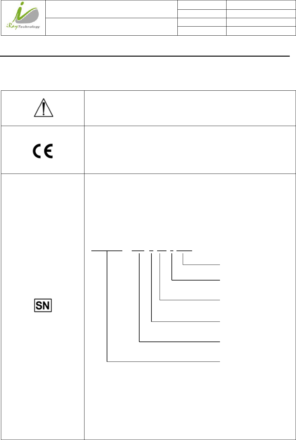
Caution: please refer to the instructions in the user manual.
This symbol is used to indicate that the equipment has passed CE testing and it
is followed by the CE number.
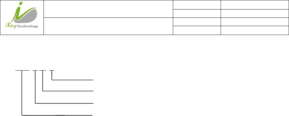
This symbol is used to identify the manufactuer’s series number which is after,
below or adjacent to the symbol. The series number of iRay products is
usually made of thirteen digits as shown below:
Numerical Order
A1A2A3A4 C1C2 M DD Y XXX
Year
Date
Month
Version
Product Code
iRay Technology (Shanghai) Ltd. Doc N0. 037‐201‐02
Version A1
Mars1717VUser’sManual Date 2015.11.06
Page 8/141
Page 8
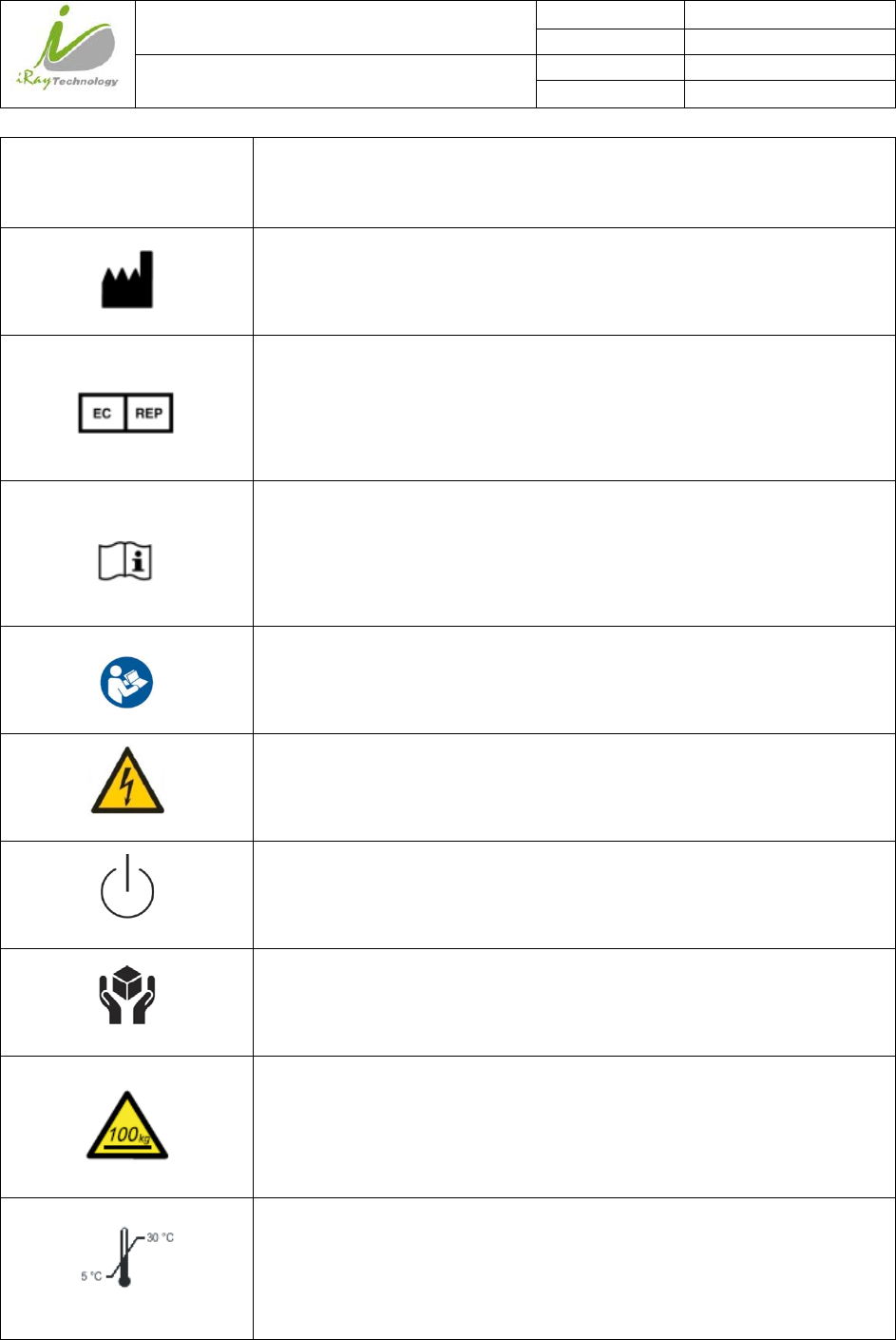
This symbol is used to indicate the name and address of the manufacturer.
This symbol is used to indicate the name and address of iRay authorized
representative in the European region.
This symbol is used to indicate consultation of the user guide for general
information.
Safety Signs: please refer to the user guide for safety instructions
Safety Signs:Dangerous Voltage
Stand-by
Handled with care
FPD is allowed to withstand 100 kg on the surface
This symbol is used to indicate the operational temperature limits.
iRay Technology (Shanghai) Ltd. Doc N0. 037‐201‐02
Version A1
Mars1717VUser’sManual Date 2015.11.06
Page 9/141
Page 9
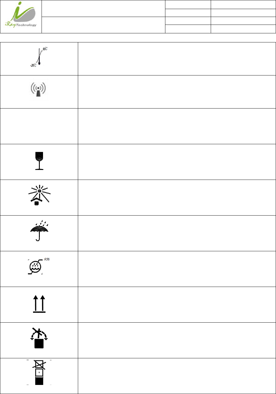
This symbol is used to indicate the storage temperature limits.
non-ionizing radiation
FCC Federal Communications Commission certificate
Package symbol, fragile.
Package symbol, keep away from sunlight
Package symbol, keep dry
Package symbol, this symbol is used to indicate the humidity limits.
Package symbol, keep the equipment up right
Package symbol, do not roll the transportation package.
Package symbol, this symbol is used to indicate stacking limit number.

iRay Technology (Shanghai) Ltd. Doc N0. 037‐201‐02
Version A1
Mars1717VUser’sManual Date 2015.11.06
Page 10/141
Page 10
Contents
To Customers 3
Symbols and Conventions 6
Labels and markings on the equipment 7
Contents 10
1Safety Information 14
1.1Safety precautions 14
1.2Notes for Using 20
2General Description 22
2.1Scope 22
2.2Model 23
2.3Characteristic 23
2.4Intended use 23
2.5Standard Product Components 24
2.6Optional Product Component 26
2.7Components Description 27
2.8Product Specification 30
2.8.1Detector 30
2.8.2Battery 32
2.8.3Battery Charger 33
2.8.4Power supply 34
2.8.5Infrared Device (Optional) 34
2.8.6AP Router (Optional) 34
2.8.7Wireless Communication 34
2.8.8Recommended Applicance Condition 35
2.8.9Mechanical Outlines 36
2.8.10Use Environment 38
3Installation 39
3.1Detector Installation 39
3.2Battery Chargering Installation 42

iRay Technology (Shanghai) Ltd. Doc N0. 037‐201‐02
Version A1
Mars1717VUser’sManual Date 2015.11.06
Page 11/141
Page 11
3.3Software Installation 43
3.4Panel Infrastructure 43
4Operation 64
4.1Main Operation 64
4.1.1Software Mode 64
4.1.2Inner Mode 67
4.1.3Isync Plus Mode 69
4.2Connection Build 71
4.3Panel Configuration 72
4.4Correction and Calibration Template Generation 72
4.4.1Pre-offset Template Generation 72
4.4.2Gain Calibration Template Generation 73
4.4.3Defect Correction Template Generation 75
4.4.4Lag Template Generation 78
4.5Image Acquisition Continually 79
4.6Image save 79
4.6.1Multiple images 79
4.6.2Single image 80
4.7Image Check and upload 81
4.7.1Local Image Check 81
4.7.2Panel Image Upload 82
4.7.3Panel Image Check 85
4.8Defect Template Check and Modification 85
4.8.1Defect Template Check 85
4.8.2Defect Template Modification 86
4.9Correction and Calibration Management 88
4.9.1Correction and Calibration template synchronization 88
4.9.2Correction and Calibration management 90
4.10Sleep and Wake Up 92
4.10.1Sleep 93
4.10.2Wake Up 95
4.11Firmware Update 95
4.11.1MCU Update 95
4.11.2FTP Server 97
4.11.3Firmware Update 99
4.12Short cut 101

iRay Technology (Shanghai) Ltd. Doc N0. 037‐201‐02
Version A1
Mars1717VUser’sManual Date 2015.11.06
Page 12/141
Page 12
4.13Software 102
4.13.1Main GUI 102
4.13.2Message Box 103
4.13.3Configuration GUI 105
4.13.4Correction and Calibration 113
4.13.5Image Check and upload 115
4.13.6Infrared Registration 116
5Regulatory Information 118
5.1Medical equipment safety standards 118
5.2Guidance and manufacture’s declaration for EMC 119
5.3Radio Frequency Compliance Information 123
5.3.1FCC Compliance 124
5.4Battery Safety Standards 124
5.5Product Label 125
5.5.1Detector 125
5.5.2Battery 127
5.5.3Battery Charger 128
6Trouble Shooting 129
6.1Cable Inspection 129
6.1.1Ethernet cable 129
6.1.2Date cable inspection 130
6.2Adapter Inspection 130
6.2.1Adapter connector definition 130
6.2.2Inspection method 131
6.3Battery Inspection 131
6.3.1Battery pin definition 131
6.3.2Inspect Method 132
6.4Dock Inspection 132
6.4.1Dock pin definition 132
6.4.2Inspection method 133
6.5Detector Main Unit Inspection 133
6.5.1Get SDK and detector log 133
6.6Power up failure inspection 135
6.7Connection inspection 135
6.7.1Connection failed in wired mode 135

iRay Technology (Shanghai) Ltd. Doc N0. 037‐201‐02
Version A1
Mars1717VUser’sManual Date 2015.11.06
Page 13/141
Page 13
6.7.2Connection Failed in Client Mode 136
6.7.3Disconnect in AP Mode 136
6.8Dark Image Acquisition After Exposure in Inner Mode 136
6.9No Image Acquire after Exposure 137
6.10Image Inspection 137
6.10.1Artifact on bright image 137
6.10.2Horizontal Line on bright image 137
6.10.3Defective line 139
6.10.4Defective point 139
6.10.5TFT broken 139
7Service Information 140
7.1Product lifetime 140
7.2Regular inspection and Maintenance 140
7.3Repair 141
7.4Replacement parts support 141
iRay Technology (Shanghai) Ltd. Doc N0. 037‐201‐02
Version A1
Mars1717VUser’sManual Date 2015.11.06
Page 14/141
Page 14
1 Safety Information
1.1 Safety precautions
Follow these safeguards and properly use the equipment to prevent injury and damage to any
equipment/data.
WARNING
Installation and environment of use
Do not use or store the equipment near flammable chemicals such as alcohol, thinner,
benzene, etc.
If chemicals are spilled or evaporate, it may result in fire or electric shock through contact
with electric parts inside the equipment. Also, some disinfectants are flammable. Be sure to
take care when using them.
Do not connect the equipment with anything other than specified.
Doing so may result in fire or electric shock.
All the patients with active implantable medical devices should be kept away from the
equipment.
Power supply
Do not operate the equipment using any type of power supply other than the one
indicated on the rating label.
Otherwise, it may result in fire or electric shock.
Do not handle the equipment with wet hands.
You may experience electric shock that could result in death or serious injury.
Do not place heavy object such as medical equipment on cables and cords. Do not pull,
bend, bundle, or step on them to prevent their sheath from being damaged, and do not
alter them neither.
Doing so may damage the cords which could result in fire or electric shock.
Do not supply power to more than one piece of equipment using the same AC outlet.
Doing so may result in fire or electric shock.
Do not turn ON the system power when condensation has formed on the equipment.
Doing so may result in fire or electric shock.
iRay Technology (Shanghai) Ltd. Doc N0. 037‐201‐02
Version A1
Mars1717VUser’sManual Date 2015.11.06
Page 15/141
Page 15
Do not connect a multiple portable socket-outlet or extension cord to the system.
Doing so may result in fire or electric shock.
To avoid the risk of electric shock, this equipment must only be connected to power
supply with protective earth.
Not doing so may result in fire or electric shock.
Securely plug the power cord into the AC outlet.
If contact failure occurs, or if metal objects come into contact with the exposed metal prongs
of the plug, fire or electric shock may result.
Be sure to turn OFF the power to each piece of equipment before connecting or
disconnecting the cords.
Otherwise, you may get an electric shock that could result in death or serious injury.
Be sure to hold the plug or connector to disconnect the cord.
If you pull the cord, the core wire may be damaged, resulting in fire or electric shock.
WARNING
Handling
Never disassemble or modify the equipment. No modification of this equipment is
allowed. Parts of the Mars1717V that are not serviced or maintained while in use with
the patient
Doing so may result in fire or electric shock. Also, since the equipment incorporates parts
that may cause electric shock as well as other hazardous parts, touching them may cause
death or serious injury.
Do not place anything on top of the equipment.
The object may fall and cause an injury. Also, if metal objects such as needles or clips fall
into the equipment, or if liquid is spilled, it may result in fire or electric shock.
Do not hit or drop the equipment.
The equipment may be damaged if it receives a strong jolt, which may result in fire or
electric shock if the equipment is used without being repaired.
Do not put the equipment and pointed objects together.
The equipment may be damaged. If so, the equipment should be used in bucky.
iRay Technology (Shanghai) Ltd. Doc N0. 037‐201‐02
Version A1
Mars1717VUser’sManual Date 2015.11.06
Page 16/141
Page 16
Have the patient take a fixed posture and do not let the patient touch parts unnecessarily.
If the patient touches connectors or switches, it may result in electric shock or malfunction
of the equipment.
When a problem occurs
Should any of the following occurs, immediately unplug the power cord of adaptor or
battery, and contact your sales representative or local iRay dealer:
When there is smoke, an odd smell or abnormal sound.
When liquid has been spilled into the equipment or a metal object has entered through an
opening.
When the equipment has been dropped and damaged.
Maintenance and inspection
Please turn OFF the power of the equipment and unplug the power cord of adaptor
before cleaning.
NEVER use alcohol, ether and other flammable cleaning agent for safety. NEVER use
methanol, benzene, acid and base because they will erode the equipment.
DON’T dip the equipment into the liquid.
Please make sure that the equipment’s surface & plugs are dry before turning ON.
Otherwise, it may result in fire or electric shock.
Clean the plug of the power cord periodically by unplugging it from the AC outlet and
removing dust or dirt from the plug, its periphery and AC outlet with a dry cloth.
If the cord is kept plugged in for a long time in a dusty, humid or sooty place, dust around
the plug will attract moisture; this could cause insulation failure that may result in a fire.
For safety reasons, be sure to turn OFF the power to each piece of equipment when
performing inspections indicated in this manual.
Otherwise, electric shocks may occur.
CAUTION
iRay Technology (Shanghai) Ltd. Doc N0. 037‐201‐02
Version A1
Mars1717VUser’sManual Date 2015.11.06
Page 17/141
Page 17
Installation and environment of use
Do not install the equipment in any of the locations listed below. Doing so may result in
failure, malfunction, equipment falling, fire or injury.
Close to facilities where water is used
Where it will be exposed to direct sunlight
Close to the air outlet of an air-conditioner or ventilation equipment
Close to heat source such as a heater
Where the power supply is unstable
In a dusty environment
In a saline or sulfurous environment
Where temperature or humidity is high
Where there is freezing or condensation
In areas prone to vibration
On an incline or in an unstable area
Take care that cables do not become tangled during use. Also, be careful not to get your
feet caught by cable.
Otherwise, it may cause a malfunction of the equipment or injury of the user due to tripping
over the cable.
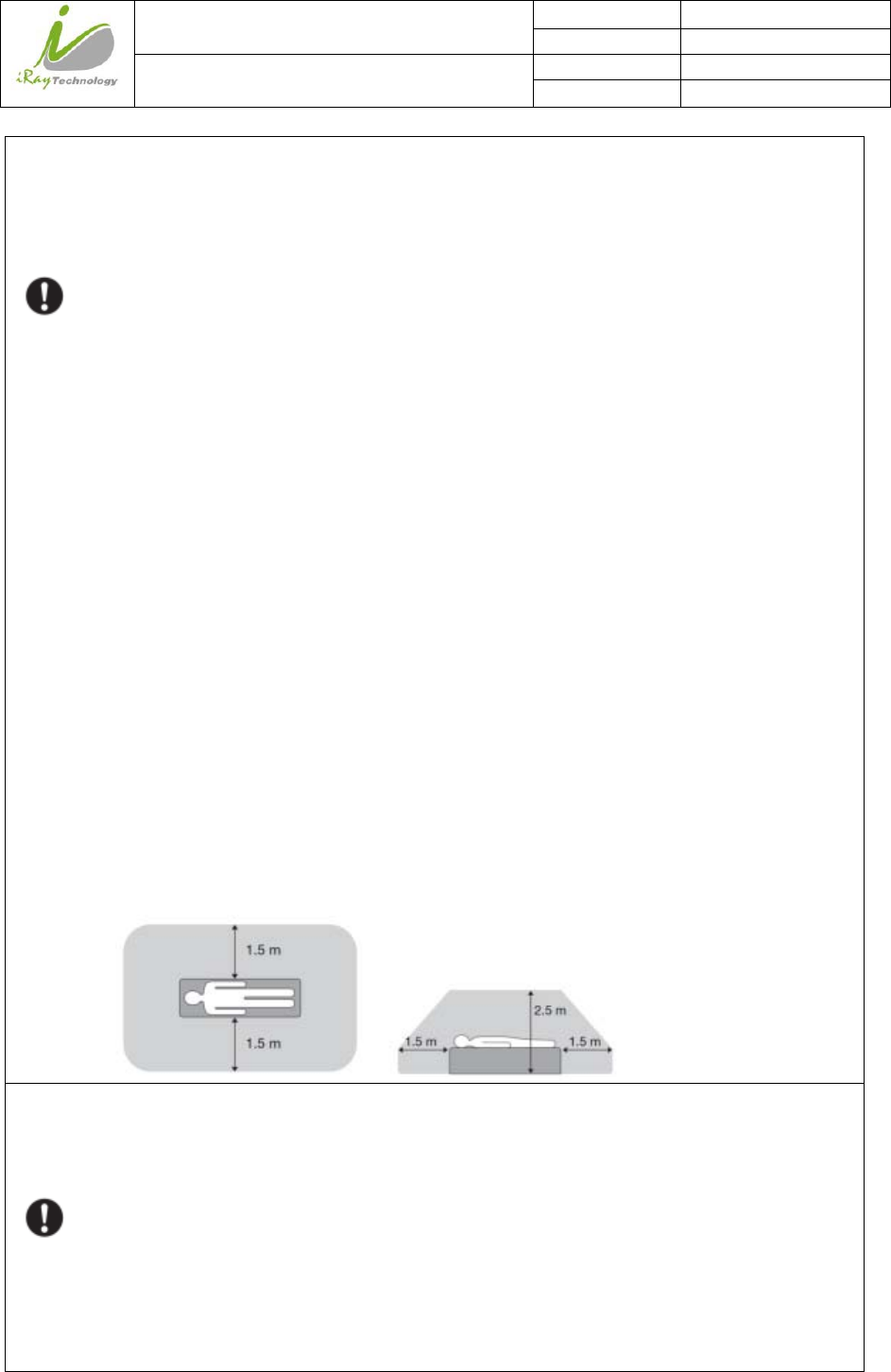
Non-medical equipment such as the battery charger, access point and IR data
communication unit cannot be used in patient’s vicinity.
Power supply
Always connect the three-core power cord plug to a grounded AC power outlet.
To make it easy to disconnect the plug at any time, avoid putting any obstacles near the
outlet. Otherwise, it may not be possible to disconnect the plug in an emergency.
Be sure to ground the equipment to an indoor grounded connector. Also, be sure to
connect all the grounds for the system to a common ground.
Do not use any power source other than the one provided with this equipment.
iRay Technology (Shanghai) Ltd. Doc N0. 037‐201‐02
Version A1
Mars1717VUser’sManual Date 2015.11.06
Page 18/141
Page 18
Otherwise, fire or electric shock may be caused due to leakage.
Handling
Do not spill liquid or chemicals onto the equipment. In case the patient is injured, it is
not allowed to contact with blood or other body fluids.
Doing so may result in fire or electric shock.
In such a situation, protect the equipment with a disposable cover as necessary.
Turn OFF the power and pull out the plug to each piece of equipment for safety when
not used.
CAUTION
Handling
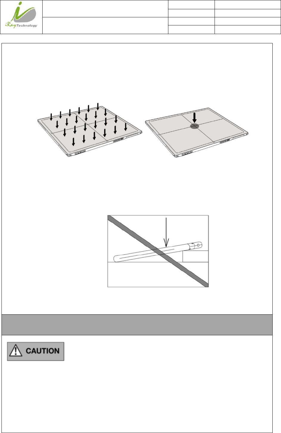
Handle the equipment carefully.
Do not submerge the equipment in water.
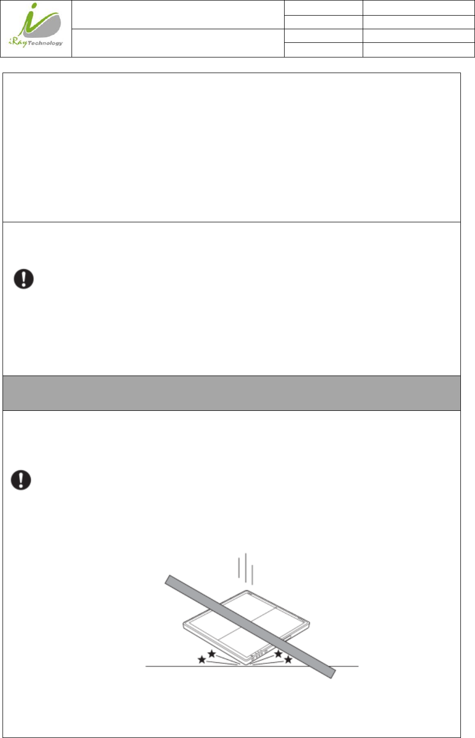
The internal image sensor may be damaged if something hits against it or it is dropped.
If the equipment is dropped, the drop sensor inside will turn red and the equipment will
not be warranted by iRay.
Do not place excessive weight on the equipment.
Otherwise, the internal image sensor may be damaged and image may be incorrect.
iRay Technology (Shanghai) Ltd. Doc N0. 037‐201‐02
Version A1
Mars1717VUser’sManual Date 2015.11.06
Page 19/141
Page 19
Be sure to use the equipment on a flat surface so it will not bend. Otherwise, the internal
image sensor may be damaged. Be sure to securely hold the detector while using it in
upright positions. Otherwise, the detector may fall over, resulting in injury to the user
or patient, or may flip over, resulting in damage to the inner device.
Keep the same load (same pressure) on the detector when acquiring the image. Or the image
will be incorrect.
CAUTION
Do not close to fire, do not use in high temperature
Do not invert positve and negative pole
Do not contact with metal in case of short circuit
Do not insert sharp objects into battery
Do not beat battery
Do not stand on battery
<Load Limit>
Uniform load:100 kg over the
whole area of the detector
surface.
Local load:100 kg on an area
4 cm diameter.

iRay Technology (Shanghai) Ltd. Doc N0. 037‐201‐02
Version A1
Mars1717VUser’sManual Date 2015.11.06
Page 20/141
Page 20
Do not use battery out of rules
Do not dispose battery or change internal structure
Do not submerge battery in water, please keep dry in storage and do not contact with water in use
Please charge battery with charger following IEC60601-1 & IEC62133 Standards provide by us
Do not mix battery with ones not provided by our company
Do not charge battery with broken charger.
1.2 Notes for Using
When using the equipment, take the following precautions. Otherwise, problems may occur and the
equipment may not function correctly.
Before exposure
Be sure to check the equipment daily and confirm that it works properly.
Be sure there be a battery installing on the Mars1717V to avoid the power off suddenly.
Sudden heating of the room in cold areas will cause condensation to form on the equipment. In
this case, wait until the condensation evaporates before performing an exposure. If the equipment
is used while condensation is formed on it, problems may occur in the quality of captured images.
When an air-conditioner is used, be sure to raise/lower the temperature gradually so that a
difference of temperature in the room and equipment does not occur, to prevent condensation.
The detector should warm up for 15 minutes before exposure or updating the gain map or defect
map.
During exposure
Do not move the power or Ethernet Cables during exposure, or it may cause image noise or artifacts,
even incorrect images.
Do not use the devices near the equipment generating a strong magnetic field. Otherwise, it may
cause image noise, artifacts or even incorrect images.
Disinfection and Cleaning
After every examination, wipe the patient contact surfaces of the detector using disinfectants such
as ethanol, to prevent the risk of infection. For details on how to sterilize, consult a specialist.
Do not spray the detector directly with disinfectants or detergents.
Wipe it with a cloth slightly damped with a neutral detergent. Do not use solvents such as alcohol,
thinner, benzene, acid and base. Doing so may damage the surface of the equipment.
It’s recommended to use a waterproof non-woven cover as the isolated layer between detector and

iRay Technology (Shanghai) Ltd. Doc N0. 037‐201‐02
Version A1
Mars1717VUser’sManual Date 2015.11.06
Page 21/141
Page 21
the blooding patient.
iRay Technology (Shanghai) Ltd. Doc N0. 037‐201‐02
Version A1
Mars1717VUser’sManual Date 2015.11.06
Page 22/141
Page 22
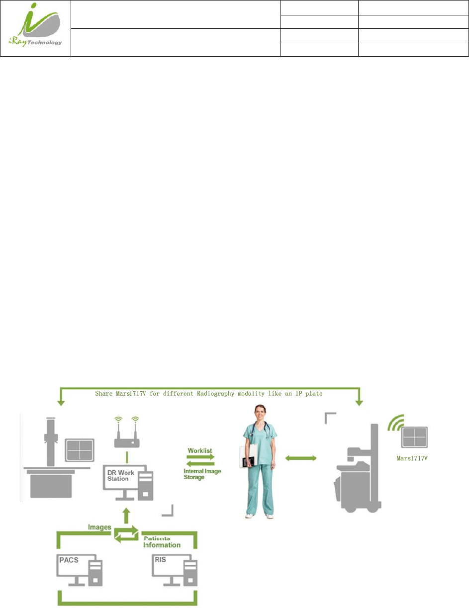
2 General Description
Mars1717V is a cassette-size wireless X-ray flat panel detector based on amorphous silicon thin-film
transistor technologies. It is developed to provide the highest quality of radiographic image, which contains
an active matrix of 3072×3072 with 139um pixel pitch. Detectors’ scitinator has two options which are
Standard GOS(Gadolinium Sulfoxylate) and CsI(CaesiumIodide). However the most great improvement is
Mars1717V supports wireless communication between detectors and PC. Mars1717V’s power supply
includes battery. Mars1717V can be used as a real portable panel.
2.1 Scope
This manual contains information about the iRay Mars1717V. All operators must read and understand this
manual before using equipment. All information in this manual, including the illustrations, is based on
equipment prototype. If configuration of your equipment does not have any of these items, information about
these items in the manual does not apply to your equipment.
iRay Technology (Shanghai) Ltd. Doc N0. 037‐201‐02
Version A1
Mars1717VUser’sManual Date 2015.11.06
Page 23/141
Page 23
2.2 Model
Mars □ □ □
PSI- GOS scintillator screen, VSI- CsI scintillator screen
Product Application:cassette size detector
Product dimension:1717,17inch×17inch
Product serials:wireless digital flat panel detector serials
Product Type: Battery-KV---------Rechargeable lithium battery
Product Type: Charger-KV--------Battery charger
2.3 Characteristic
Wireless static Flat Panel Detector used for general radiography.
17 × 17 inch
Sync-Shot exposure trigger
GOS or CsI scintillation screen.
Easy to change the cable and upgrade firmware.
Battery recycling
2.4 Intended use
This equipment provides digital X-ray imaging for diagnosis of disease, injury, or any applicable health
problem. The image is obtained as the result of X-ray passing through the human body and detected by the
equipment. This device is intended to be used in the holder or bucky which is well insulated to panel. The
holder or the bucky is well grounded. This panel is not intended for directly contacting with patient
iRay will provide equipment and software support for integration of system. The length of both Ethernet
Cable and DC Power Cable cannot exceed 3.5 m. or the impedance of protective earth connections may
exceed the safety threshold.
This panel is not intended for mammography or dental applications,and prohibited for pregnant women and
children.
According to the Mars1717V intended use and the result of risk management, identifying and describing the
essential performance as the following:
a) To get imaging of dark field, the Mars1717V shall be not influenced to the imaging acquisition
iRay Technology (Shanghai) Ltd. Doc N0. 037‐201‐02
Version A1
Mars1717VUser’sManual Date 2015.11.06
Page 24/141
Page 24
b) To keep the data transmission function, the Mars1717V shall be not influenced to the data and signal
transmission
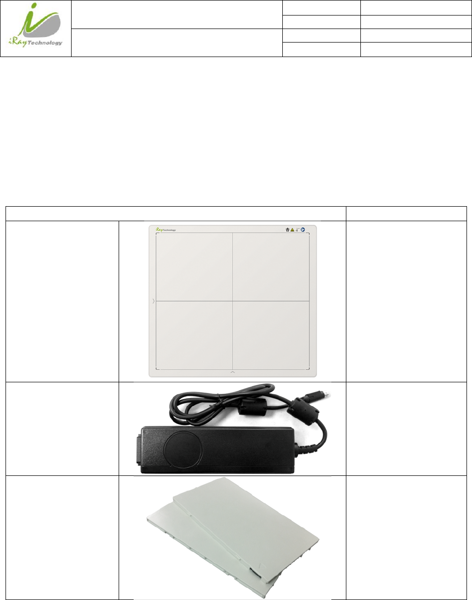
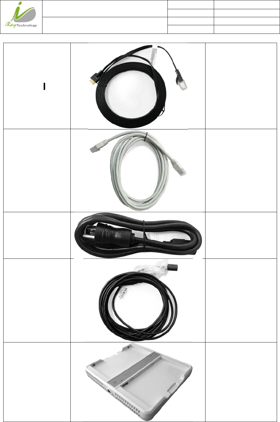
2.5 Standard Product Components
Mars1717V comes with power supply both 24V DC and battery package. Once powered on, it would build a
connection with PC through Ethernet cable or Wireless connection.
Item Description
Mars1717V Detector 1 pcs
Main Unit
Medical Adapter for
Detector and
Battery Charger
2 pcs
DC 24V
Battery Pack 2 pcs
Battery-KV
iRay Technology (Shanghai) Ltd. Doc N0. 037‐201‐02
Version A1
Mars1717VUser’sManual Date 2015.11.06
Page 25/141
Page 25
Ethernet Cable 1 pcs
3.5 m
Gigabit Ethernet Cable 1 pcs
3 m
AC Power Cable 2 pcs
DC Power cable 1 pcs
3.5 m
Battery Charger 1 pcs
iRay Technology (Shanghai) Ltd. Doc N0. 037‐201‐02
Version A1
Mars1717VUser’sManual Date 2015.11.06
Page 26/141
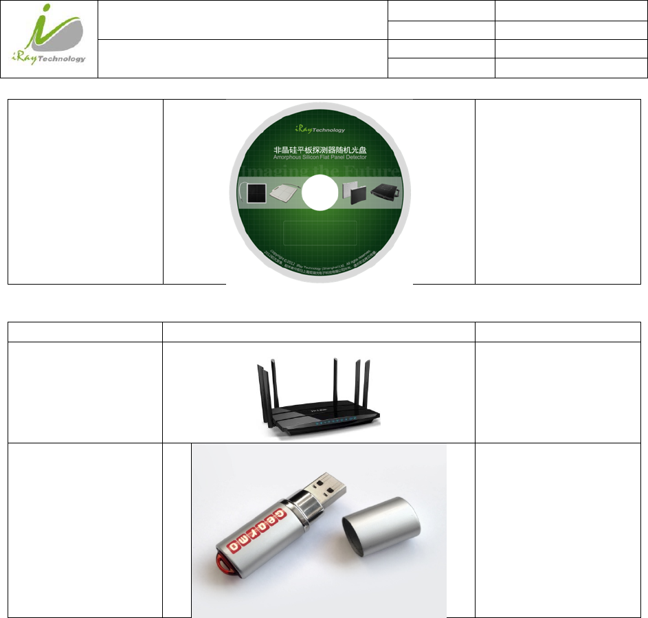
Page 26
CD-Rom
1 pcs
Gain correction data
Defect correction map
SDK
Manual
2.6 Optional Product Component
Item Description
Wireless AP Device 1 pcs
Infrared Device 1 pcs
iRay Technology (Shanghai) Ltd. Doc N0. 037‐201‐02
Version A1
Mars1717VUser’sManual Date 2015.11.06
Page 27/141
Page 27
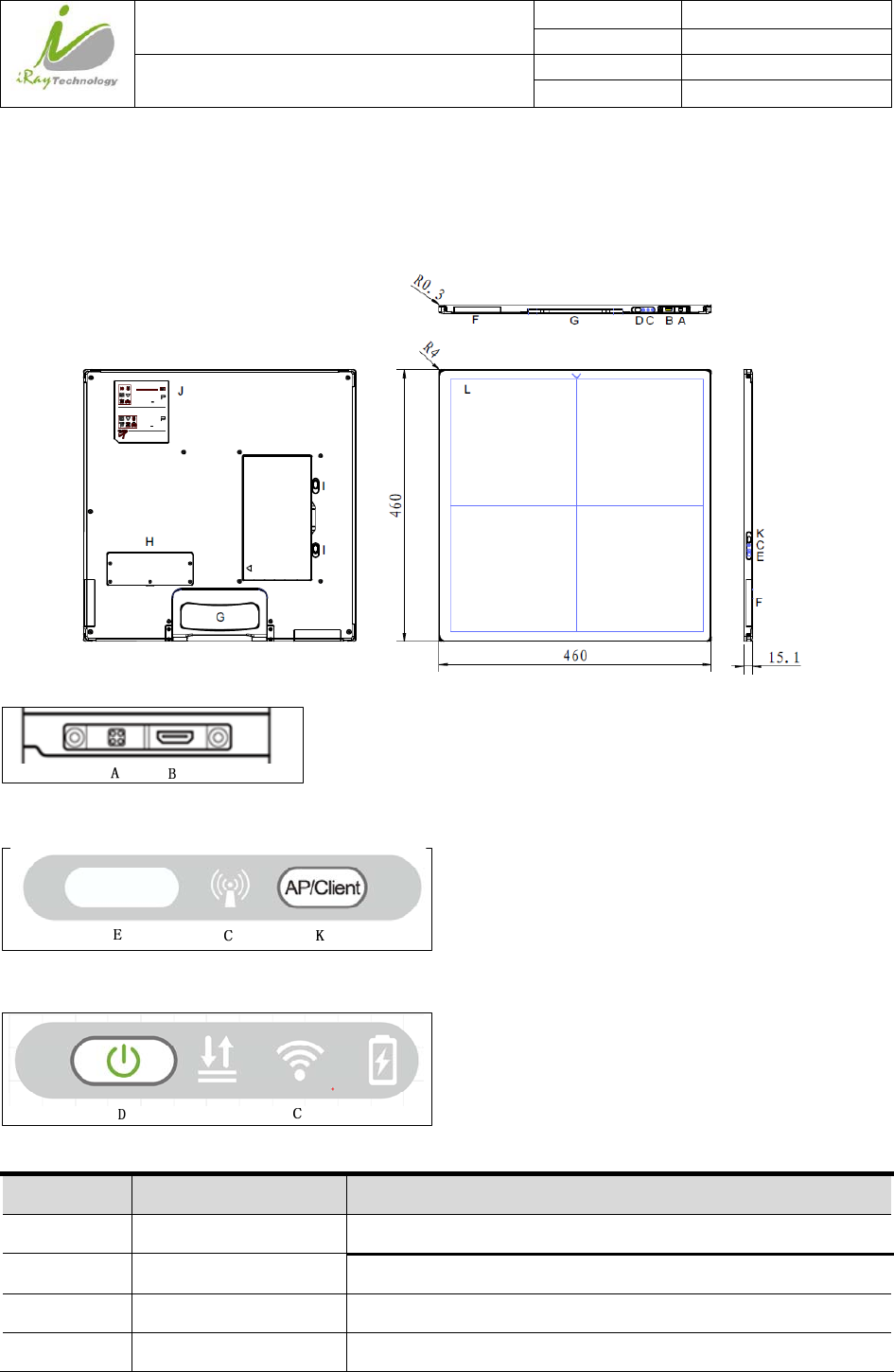
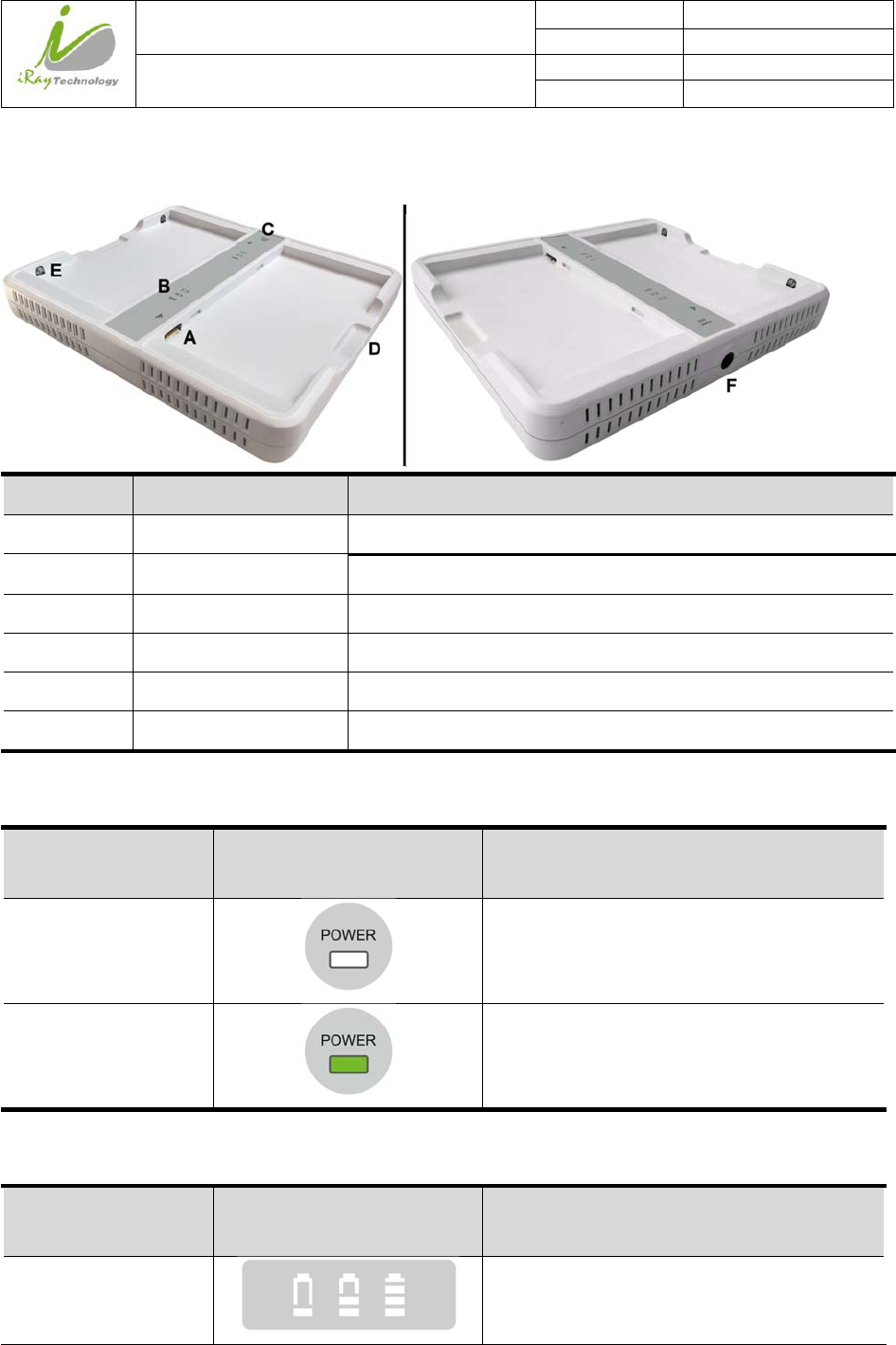
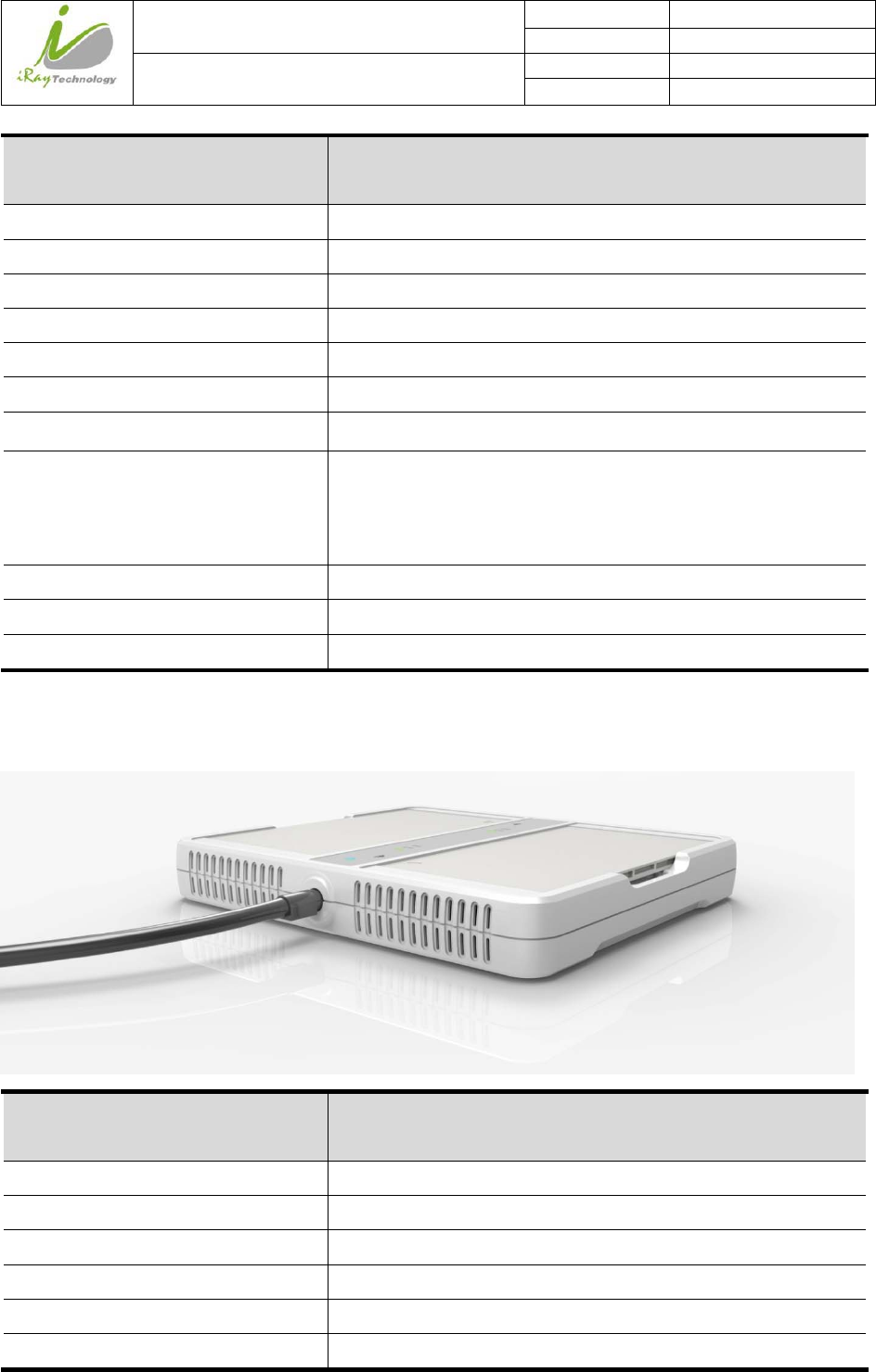
2.7 Components Description
2.7.1.1 Detector
External Signals Input
Control Panel
Control Panel
Item Name Description
A DC Input Interface 24V DC input
B Ethernet Interface Gigabit Ethernet Wire
C Detector Indicator Detector indicator of control panel
D Power Button Power button of control panel
iRay Technology (Shanghai) Ltd. Doc N0. 037‐201‐02
Version A1
Mars1717VUser’sManual Date 2015.11.06
Page 28/141
Page 28
E Infrared Window Infrared device window
F Antenna Antenna
G Handle For the panel carried
H Maintenance Cover For service engineer to maintenance
I Battery Lock The lock button for detaching battery
J Detector Label Product information.
K Switch AP/Client Mode Switch
L Carbon Film Panel Carbon Film, have biocompatibility
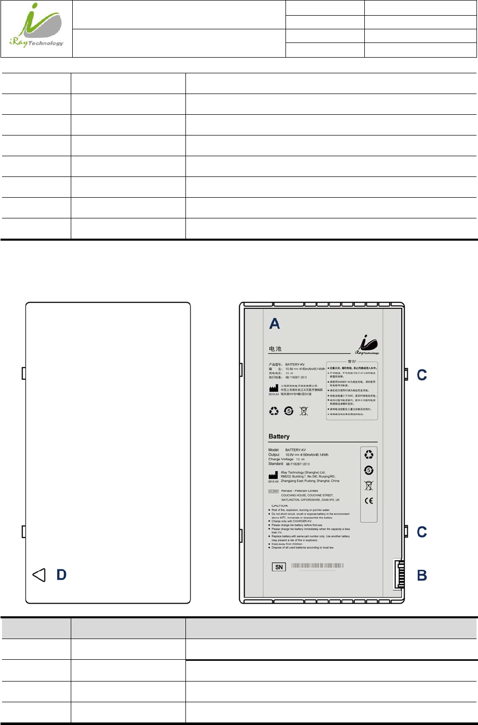
2.7.1.2 Battery
Item Name Description
A Battery Label /
B Battery Interface 8 Pin Battery connector
C The location pin /
D Indicator Installation direction indicator
iRay Technology (Shanghai) Ltd. Doc N0. 037‐201‐02
Version A1
Mars1717VUser’sManual Date 2015.11.06
Page 29/141
Page 29
2.7.1.3 Battery Charger
Item Name Description
A Battery Interface 8 Pin Battery connector
B Capacity Indicator The indicator definition is as follow
C Power Indicator The indicator definition is as follow
D Hand Pull Position /
E The limit ball plug /
F DC Jack 24V DC input
Power indicator definition:
Power Indicator Lighting Status Operating Status
OFF
No external DC adaptor input
GREEN ON
External DC adaptor input
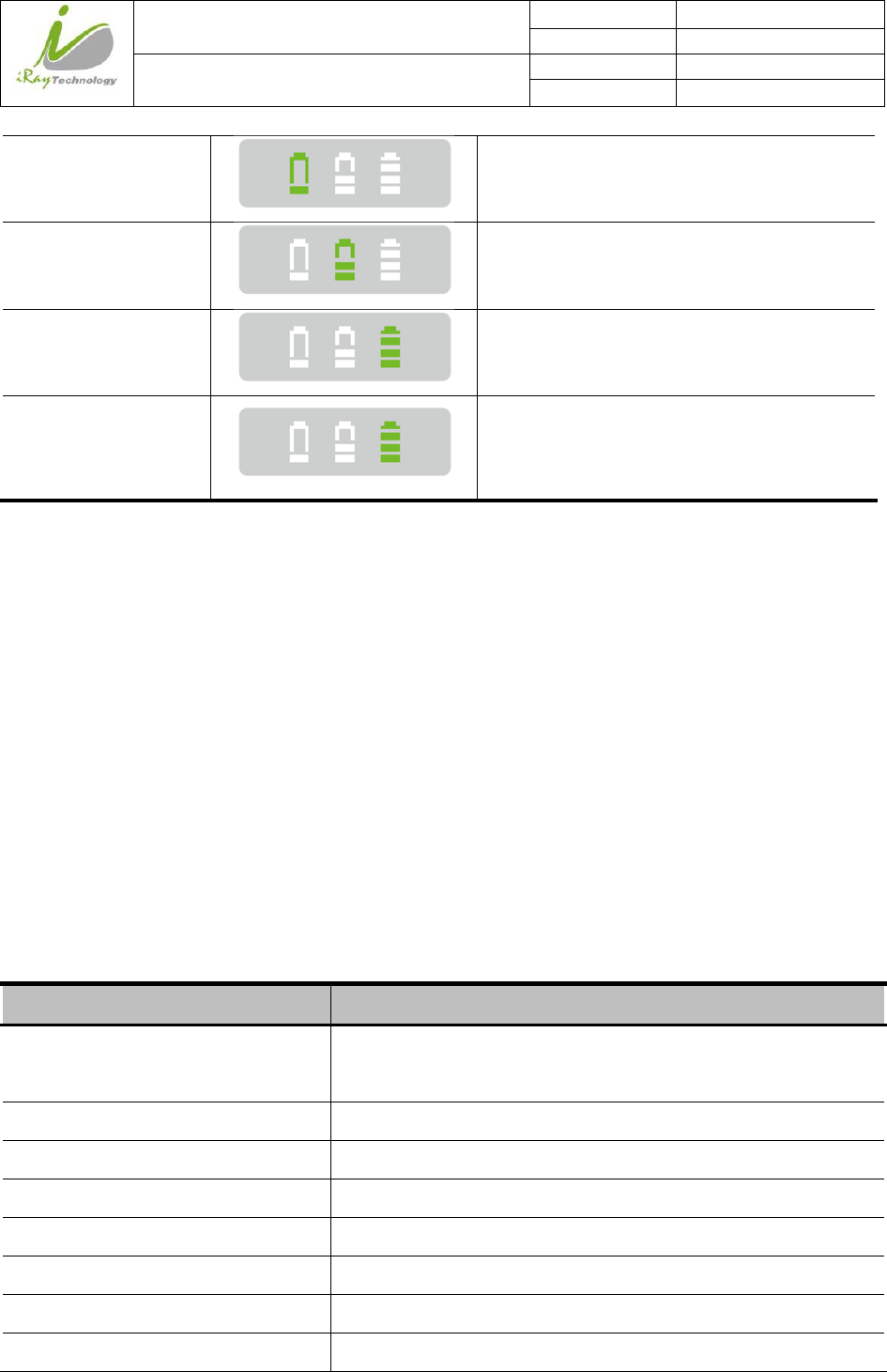
The battery charging capacity indicator definition:
X Group Indicator Lighting Status Operating Status
I, II and III grid OFF
No battery Insert
iRay Technology (Shanghai) Ltd. Doc N0. 037‐201‐02
Version A1
Mars1717VUser’sManual Date 2015.11.06
Page 30/141
Page 30
I grid blinking
II and III grid OFF
Battery Insert with capacity ≤30%,charging
II grid blinking
I and III grid OFF
Battery Insert with capacity >30% and ≤60%,
charging
III grid blinking
I and II grid OFF
Battery Insert with capacity >60% and ≤95%,
charging
I and II grid OFF
III grid ON
Battery Insert with capacity >95% and
charging, when capacity = 100%, charging can
stop automatically
2.7.1.4 Power Supply
Mars1717V supports both DC Power and Battery package input.
2.7.1.5 Infrared Device
Mars1717V does not include Infrared Device. Users can select by themselves, however some basic
requirements should be followed.
2.8 Product Specification
2.8.1 Detector
2.8.1.1 Basic
Item Specification
Model Mars1717V-PSI (GOS)
Mars1717V-VSI (CsI)
Image Sensor a-Si (Amorphous Silicon) TFT
Pixel Size 139 μm
Effective Array 3072 x 3072
Effective Area (H x V) 427 x 427 mm
Fill Factor 60%
Greyscales 14bit
Spatial Resolution 2.8 Lp/mm (Standard GOS)
iRay Technology (Shanghai) Ltd. Doc N0. 037‐201‐02
Version A1
Mars1717VUser’sManual Date 2015.11.06
Page 31/141
Page 31
3.1Lp/mm (CsI)
Image Acquisition Time (Wired) Preview Acquisition Time : 6 sec
Processed Acquisition Time : 10 sec. (including Preview Time)
Image Acquisition Time (Wireless)
Both AP mode and Client mode
Preview Acquisition Time : 9 sec.
Processed Acquisition Time : 16 sec. (including Preview Time)
Cycle Time Min. 13s @Wired;Min.16s @Wireless
Power Consumption Max. 16W
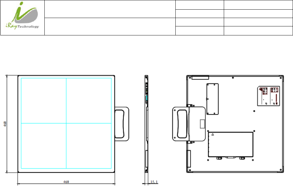
Dimension (L × W × H) 460 x 460 x 15.2 mm
Weight (with one battery) Mars1717V-PSI: 4.3 kg without battery, 4.6 kg with battery
Mars1717V-VSI: 4.5 kg without battery, 4.8 kg with battery
Image Transfer Wired : Gigabit Ethernet(1000BASE-T)
Wireless : IEEE802.11a/b/g/n
Data Transmission Rate (Wireless) 802.11b : Max. 11Mbps
802.11a/g : Max. 54Mbps
802.11n : Max. 300Mbps (MIMO 2x2)
X-ray Energy 40kV to 150kV
2.8.1.2 MTF
The MTF with GOS should meet the following table
Spatial frequency (lp/mm) MTF (GOS) MTF(CsI)
1.0 0.39 0.60
2.0 0.12 0.31
3.0 0.04 0.15
2.8.1.3 DQE
The DQE with GOS should meet the following table
iRay Technology (Shanghai) Ltd. Doc N0. 037‐201‐02
Version A1
Mars1717VUser’sManual Date 2015.11.06
Page 32/141
Page 32
Spatial frequency (lp/mm)@RQA5 DQE (GOS)@3.2uGy DQE (CsI)@2.5uGy
0 0.30 0.52
1.0 0.15 0.39
2.0 0.05 0.24
3.0 0.01 0.16
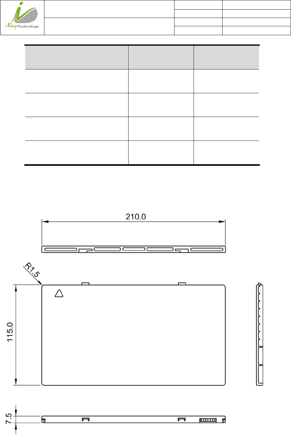
2.8.2 Battery
iRay Technology (Shanghai) Ltd. Doc N0. 037‐201‐02
Version A1
Mars1717VUser’sManual Date 2015.11.06
Page 33/141
Page 33
Item Specifications
Model Battery-KV
Rated Capacity Min. 3950mAh, Typ. 4180mAh @ Discharge 0.2C
Nominal Voltage 10.8V
Charge Voltage 12.6±0.05V
Discharged End Voltage 8.25V
Charging Method CC-CV
Operating Temperature Charge 0℃-+45℃, Discharge -20℃-+60℃
Storage Temperature
1 month -20℃-+45℃
3 month 0℃-+30℃
6 month 5℃-+20℃
Relative Humidity 65±20%
Dimension (L × W × H) 210 x 115 x 7.5 mm
Weight 0.29 kg
2.8.3 Battery Charger
Item Specifications
Model Charger-KV
Simultaneous Charging 2 battery packs
Full charging time 2 hours
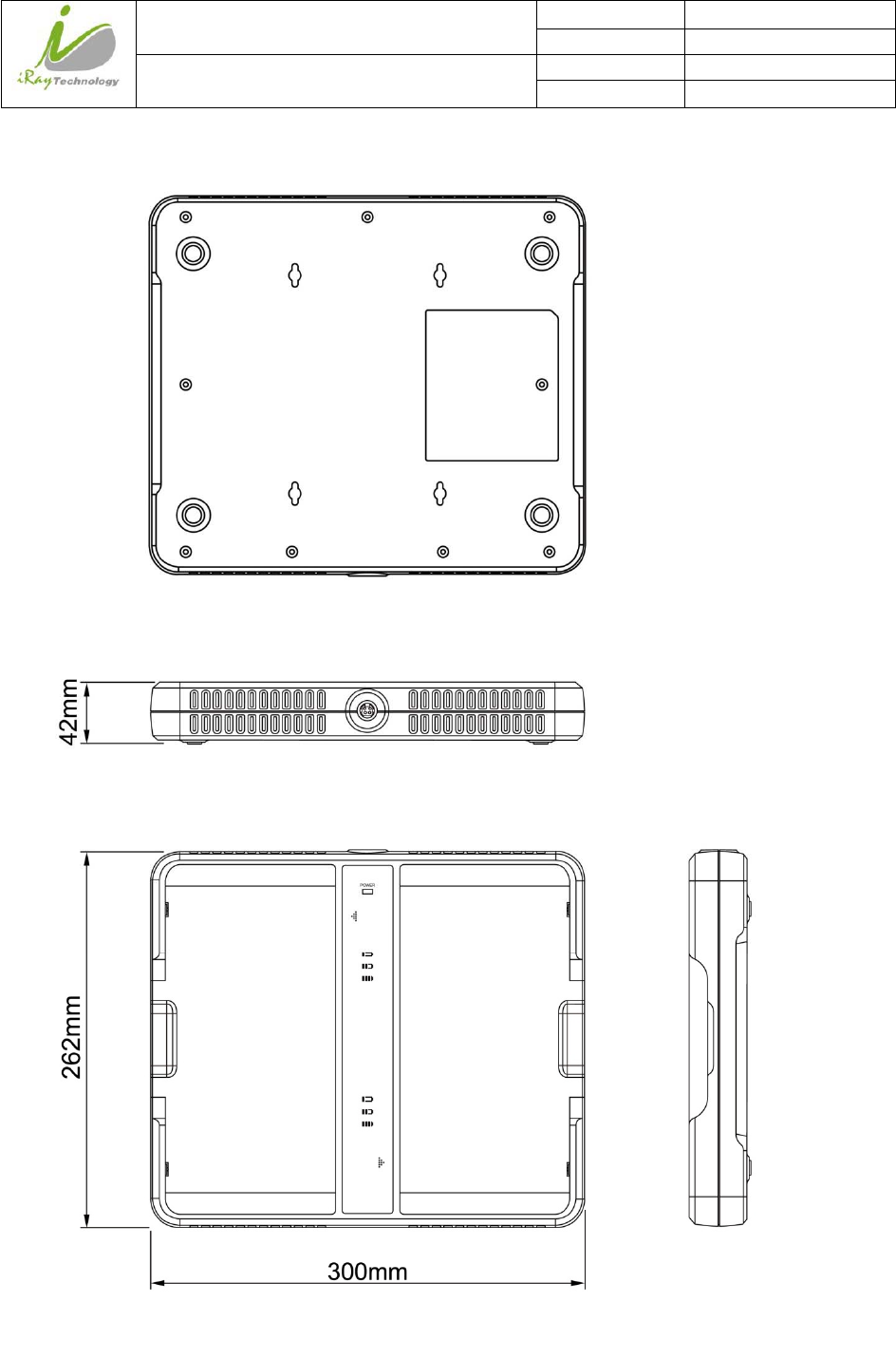
Rated power supply 24V(DC)
Dimension (L × W × H) 300 x 263 x 42 mm
Weight 1.26 kg
iRay Technology (Shanghai) Ltd. Doc N0. 037‐201‐02
Version A1
Mars1717VUser’sManual Date 2015.11.06
Page 34/141
Page 34
2.8.4 Power supply
Mars1717V supports both DC Power and Battery package input.
Item Specifications
DC Power 24V(DC), 0.8A
Battery Package 10.8V(DC),1.78A
2.8.5 Infrared Device (Optional)
Mars1717V does not include Infrared Device. Users can select by themselves, however some basic
requirements should be followed.
Item Specifications
IRDA Protocol Compliant with IrDA V1.0 and V1.1
USB Compliant with USB V2.0 and V1.1
Data Rate Max. 4Mbps
2.8.6 AP Router (Optional)
Mars1717V do not include AP Router. Users can select AP Router as they wish, however specification below is a
requirements.
Item Specifications
Wireless Standard IEEE 802.11 a/b/g/n
Frequency Range 2.412 ~ 2.4835 GHz and 5.15 ~ 5.85 GHz
Wireless Data Rate
802.11b : Max. 11Mbps
802.11a/g : Max. 54Mbps
802.11n : Max. 300Mbps (MIMO 2x2)
Wired Data Rate Max. 1Gbps
2.8.7 Wireless Communication
Item Description
Wireless Standard IEEE802.1a/b/g/n
Frequency Range
2.4G: 2.412 ~ 2.4835 GHz
11: (Ch. 1-11) – United States
13: (Ch. 1-13) – Europe
iRay Technology (Shanghai) Ltd. Doc N0. 037‐201‐02
Version A1
Mars1717VUser’sManual Date 2015.11.06
Page 35/141
Page 35
14: (Ch. 1-14) – Japan
5G: 5.15 ~ 5.85 GHz
12: United States
19: Europe
8: Japan
Data Transmission Rate
802.11b : Max. 11Mbps
802.11a/g : Max. 54Mbps
802.11n : Max. 300Mbps (MIMO 2x2)
Modulation
802.11b:
CCK, DQPSK, DBPSK
802.11a/g:
64 QAM, 16 QAM, QPSK, BPSK
802.11n:
64 QAM, 16 QAM, QPSK, BPSK
Transmission Power Max.17dBm
Security WPA, WPA-PSK, WPA2, WPA2-PSK, WEP 64bit & 128bit
Antenna 2 Dual Band internal antenna
2.8.8 Recommended Applicance Condition
Item Description
Operating System Windows XP/7 32/64bit
CPU Intel Core i73.6G
Memory 4G DDR3
Hard Disk 160 G
LAN Card
Intel Pro EXP9301CT PRO
Gigabit Network Adapter with PCIe interface
iRay Technology (Shanghai) Ltd. Doc N0. 037‐201‐02
Version A1
Mars1717VUser’sManual Date 2015.11.06
Page 36/141
Page 36
2.8.9 Mechanical Outlines
iRay Technology (Shanghai) Ltd. Doc N0. 037‐201‐02
Version A1
Mars1717VUser’sManual Date 2015.11.06
Page 37/141
Page 37

iRay Technology (Shanghai) Ltd. Doc N0. 037‐201‐02
Version A1
Mars1717VUser’sManual Date 2015.11.06
Page 38/141
Page 38
2.8.10 Use Environment
Temperature
Temperature
change Humidity AtmosphericPr
essure Pressure Change
Operating 5~30℃ <1k/min 45~85% RH
700~1000hPa1
0~70% RH
<10kp/min
(1kp=1.0197E-5Pa)
Storage -20~60℃ <1k/min 45~85%RH
700~1000hPa1
0~70% RH
<10kp/min
(1kp=1.0197E-5Pa)
The Mars1717V serial detectors shall operate at an altitude specified not more than 3000m.
iRay Technology (Shanghai) Ltd. Doc N0. 037‐201‐02
Version A1
Mars1717VUser’sManual Date 2015.11.06
Page 39/141
Page 39
3 Installation
3.1 Detector Installation
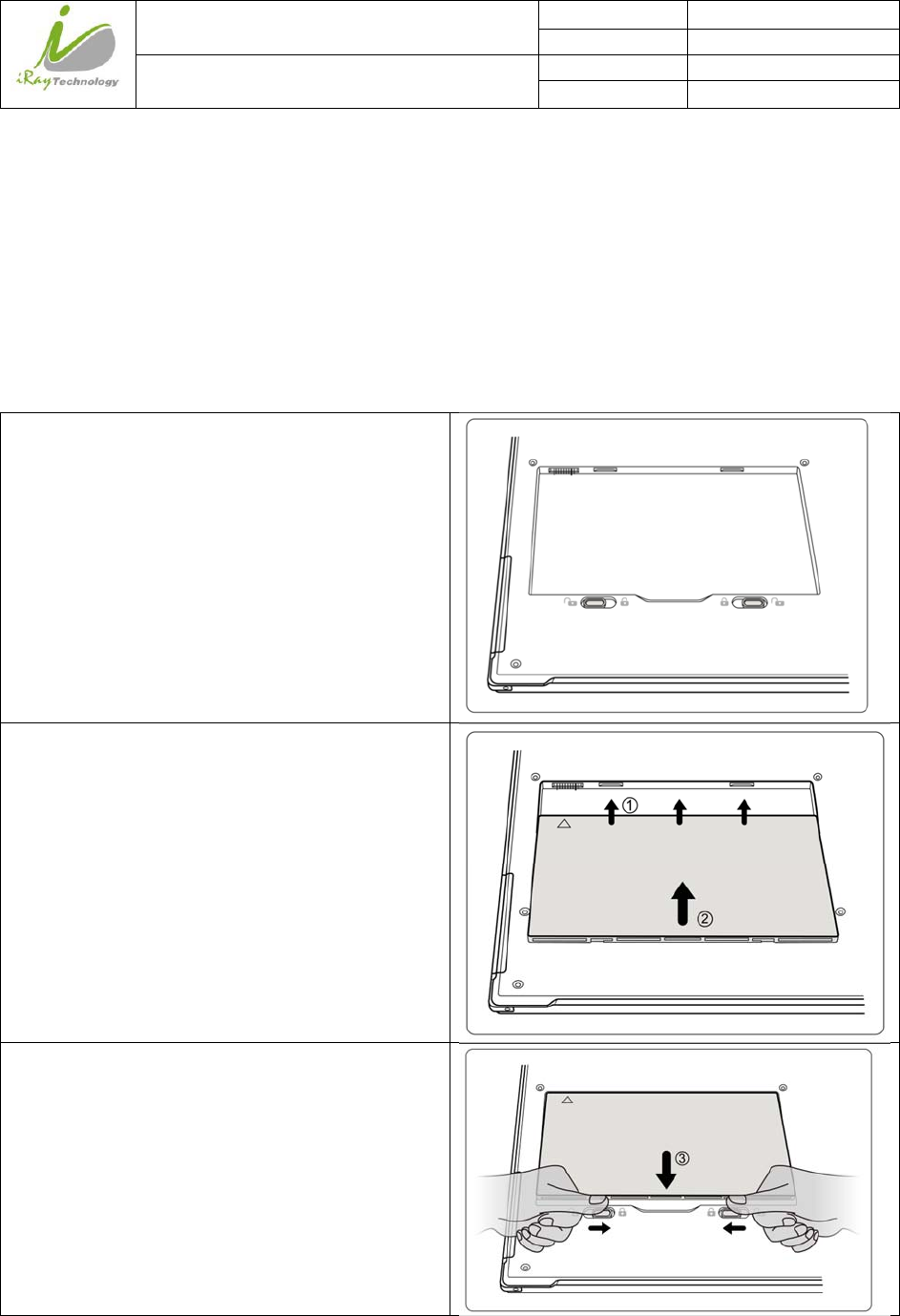
3.1.1.1 Attach Battery Pack
Mars1717V can be powered on by both battery package and DC power. Once battery package is inserted or
DC power is on, Detectors would be activated immediately. If none of battery and DC power is on,
Mars1717V would power off. Please see below for battery installation.
Make sure that the connectors on the battery package
are pointed to the cave in battery compartment.
Slide battery package into battery compartment
(Make sure battery capacity overpass 10%).
Slide the battery lock lever.
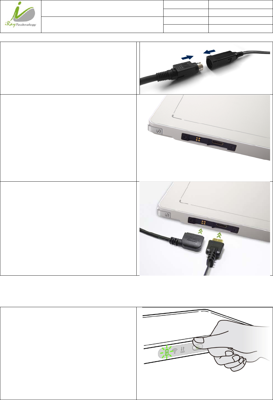
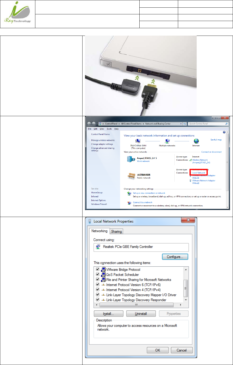
3.1.1.2 Attach DC Power
Please see below for DC power installation.
iRay Technology (Shanghai) Ltd. Doc N0. 037‐201‐02
Version A1
Mars1717VUser’sManual Date 2015.11.06
Page 40/141
Page 40
Connect one end of DC Power Cable to the Medical
Adapter
As figure is power interface and Ethernet interface
Connect another end of DC Power Cable to the DC
input of the detector.
If user want to use wired Ethernet, connect the
Ethernet cable to Ethernet interface.
3.1.1.3 Booting Up
On the control panel, user can press power button to power on/off.
If detector is powered off, users can press the button
for 4 seconds to power on the detector when battery
is inserted and battery capacitor is not less than 10%,
or direct current power is connected.
If detector is powered on, users can press the button
for 4 seconds to shut down the detector. On the other
hand, it can also be used as reset internal control IC
when button is active for 8s.
iRay Technology (Shanghai) Ltd. Doc N0. 037‐201‐02
Version A1
Mars1717VUser’sManual Date 2015.11.06
Page 41/141
Page 41
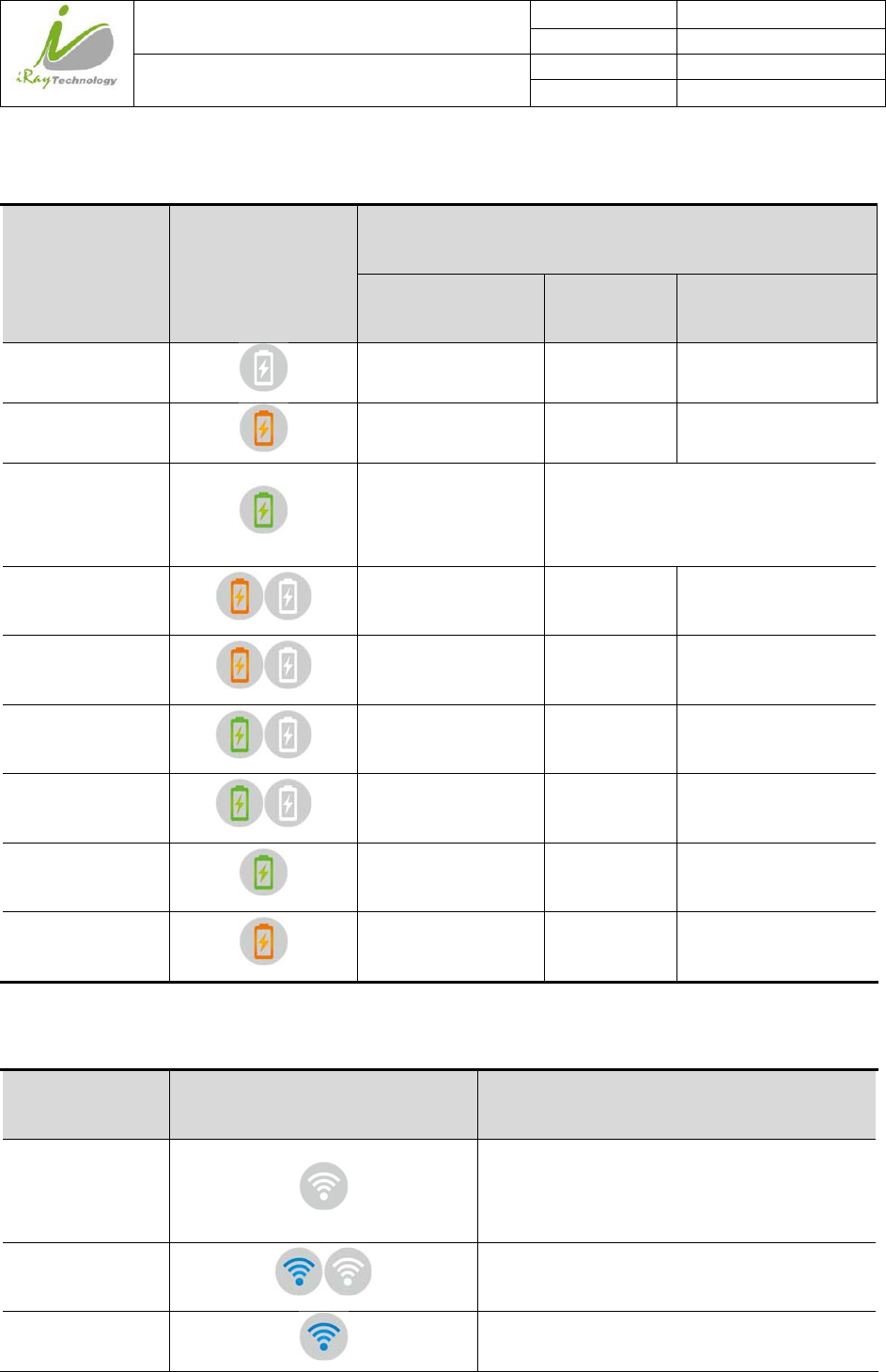
After booting up the detector, use can check the status LED indicator of detector.
Power Indicator Lighting Status
Operating Status
Operating Battery
Capacity DC Input
OFF Power OFF / /
Orange ON Power ON ≤10% NO
Green ON Power ON
Battery Capacity >10%, NO DC
Input
No Battery with DC Input
Orange Fast
Blinking
Power OFF ≤10% YES
Orange Slow
Blinking Power ON ≤10% YES
Green Fast
Blinking Power OFF >10% YES
Green Slow
Blinking Power ON >10% YES
OFF after Green
ON with 1 sec. Power OFF >10% NO
OFF after Orange
ON with 1 sec. Power OFF ≤10% NO
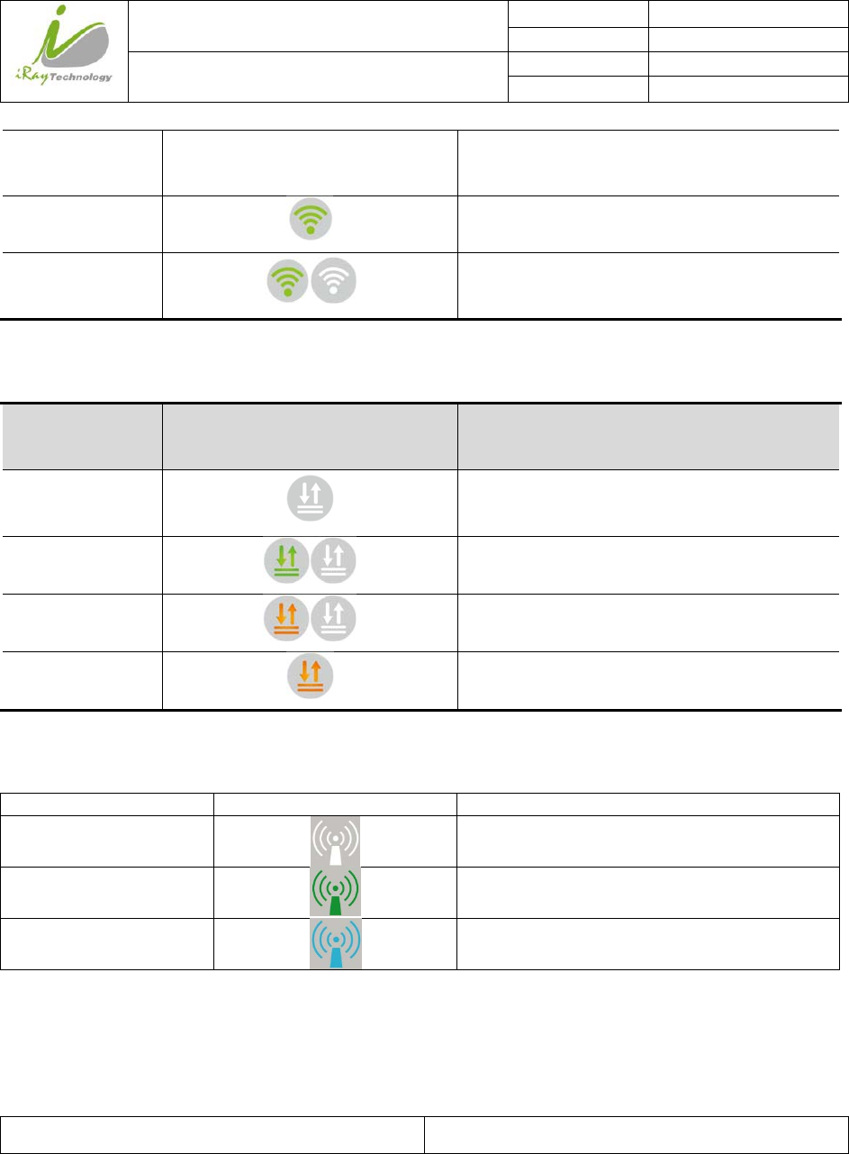
Link indicator is as table:
Link Indicator Lighting Status Description
OFF
Panel shut down
wired connection broken and wireless
connection not ready
Blue blinking
Client mode, wireless connection is ready
for connection, but not connected
Blue ON
Client mode, wireless connection is built
iRay Technology (Shanghai) Ltd. Doc N0. 037‐201‐02
Version A1
Mars1717VUser’sManual Date 2015.11.06
Page 42/141
Page 42
AP mode, wireless AP is ready for
connecting
Green ON
Wired Connection is built
Green blinking
Panel Initialization
Infrared configuration
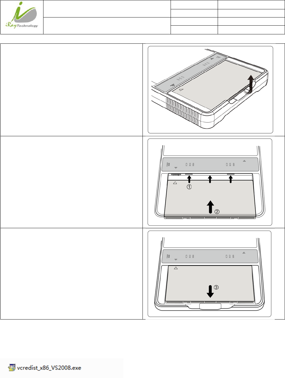
Status indicator is as table:
Status Indicator Lighting Status Description
OFF
Panel shut down
Panel is idle
Green ON
Data Transmission
Orange blinking
Fatal Error
Orange ON
Panel Initialization
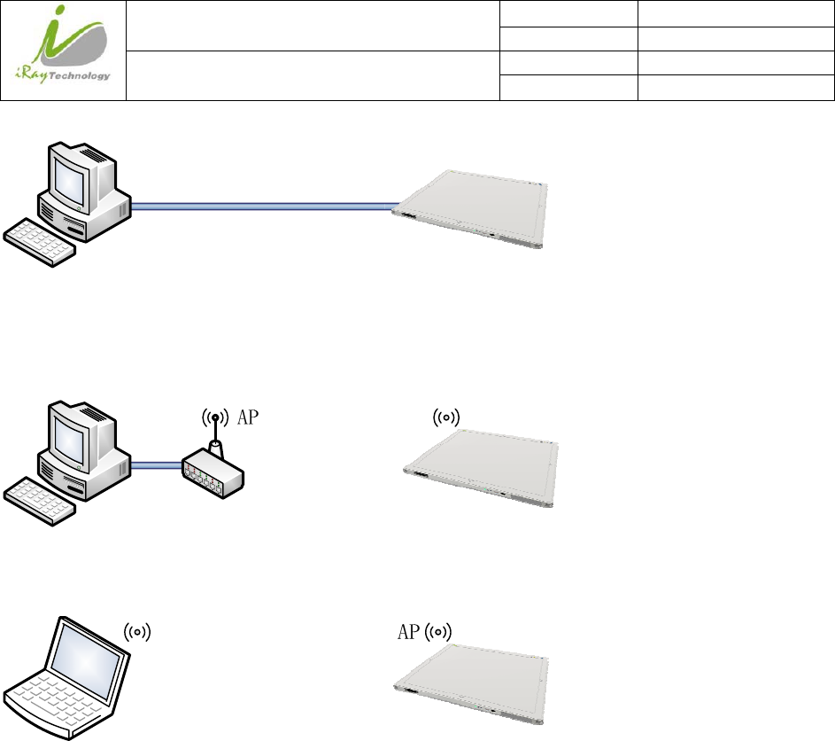
AP/Client indicator is as table:
AP/Client Indicator Lighting Status Description
OFF
1. Network connection error;
2. Network connection is wired connection;
Green ON
Wireless connection ok,connection mode is
AP
Blue ON
Wireless connection ok,connection mode is
Client
3.2 Battery Chargering Installation
Operating Figure
iRay Technology (Shanghai) Ltd. Doc N0. 037‐201‐02
Version A1
Mars1717VUser’sManual Date 2015.11.06
Page 43/141
Page 43
Unload Battery from battery charger.
Insert battery into battery charger. Note align the
interface position as figure.
Press the battery to the bottom of battery
compartment.
3.3 Software Installation
In the case of IDemo doesn’t work, please install following VC redistribute package.
3.4 Panel Infrastructure
Mars1717V supports three connection modes as follows:
1) Wired connection mode
iRay Technology (Shanghai) Ltd. Doc N0. 037‐201‐02
Version A1
Mars1717VUser’sManual Date 2015.11.06
Page 44/141
Page 44
2) Wireless Client Mode
3) Wireless AP Mode
To build connection between workstation and Panel, User should follow steps below.
3.4.1.1 Wired Mode
To complete Wired connection configuration, users have to finish actions listed below.
Configuration of Ethernet Card
To begin configuration of Ethernet Card, users should finish 31.1.2
iRay Technology (Shanghai) Ltd. Doc N0. 037‐201‐02
Version A1
Mars1717VUser’sManual Date 2015.11.06
Page 45/141
Page 45
Connect detector to PC with Ethernet
Cable
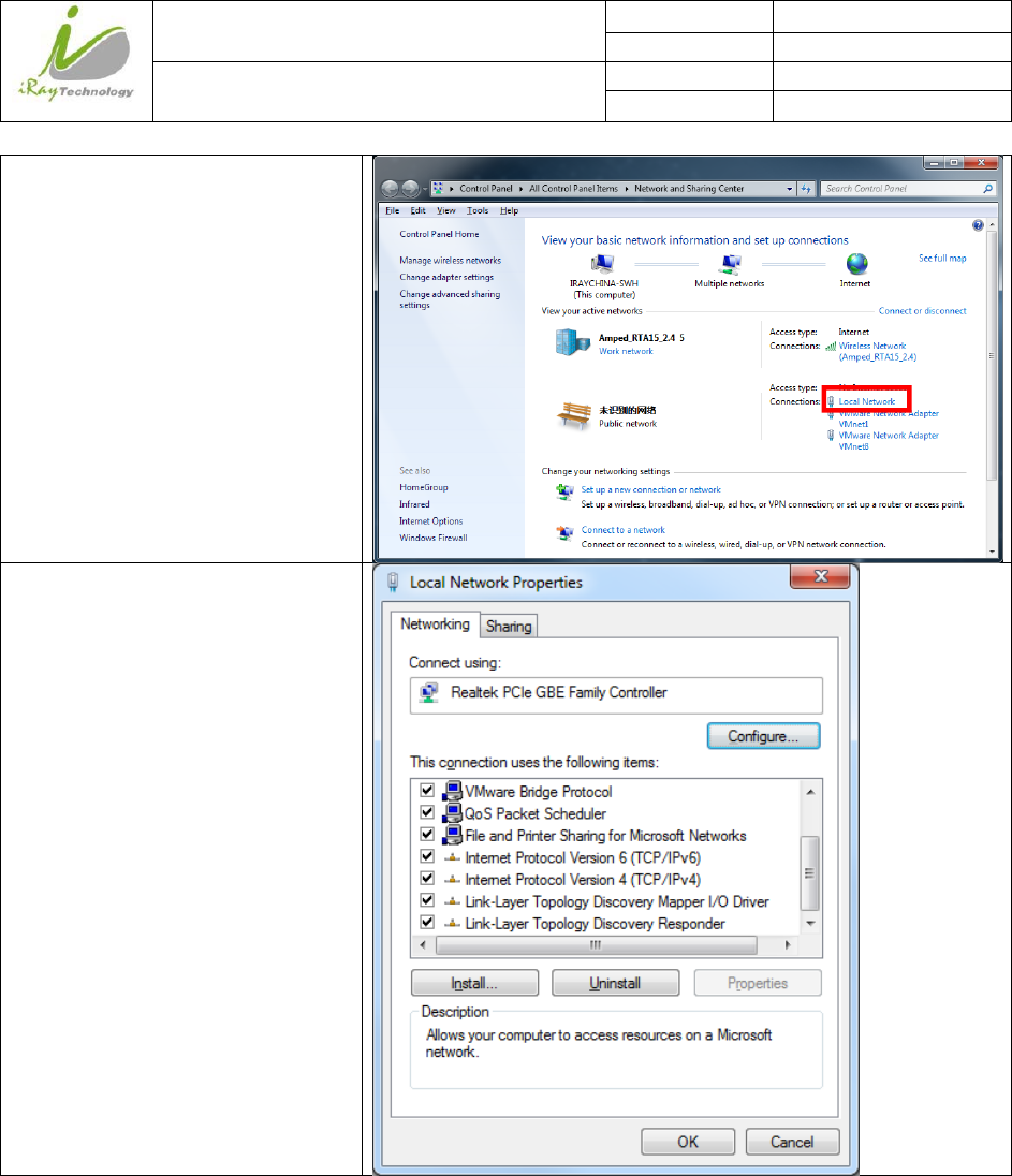
Open Network configuration
Open Local network configuration
iRay Technology (Shanghai) Ltd. Doc N0. 037‐201‐02
Version A1
Mars1717VUser’sManual Date 2015.11.06
Page 46/141
Page 46
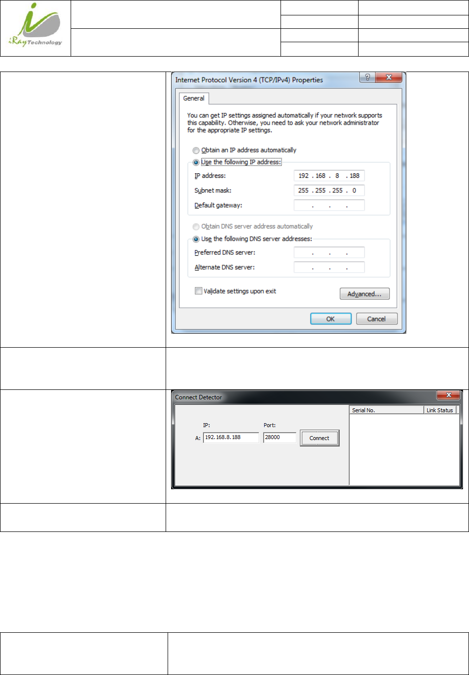
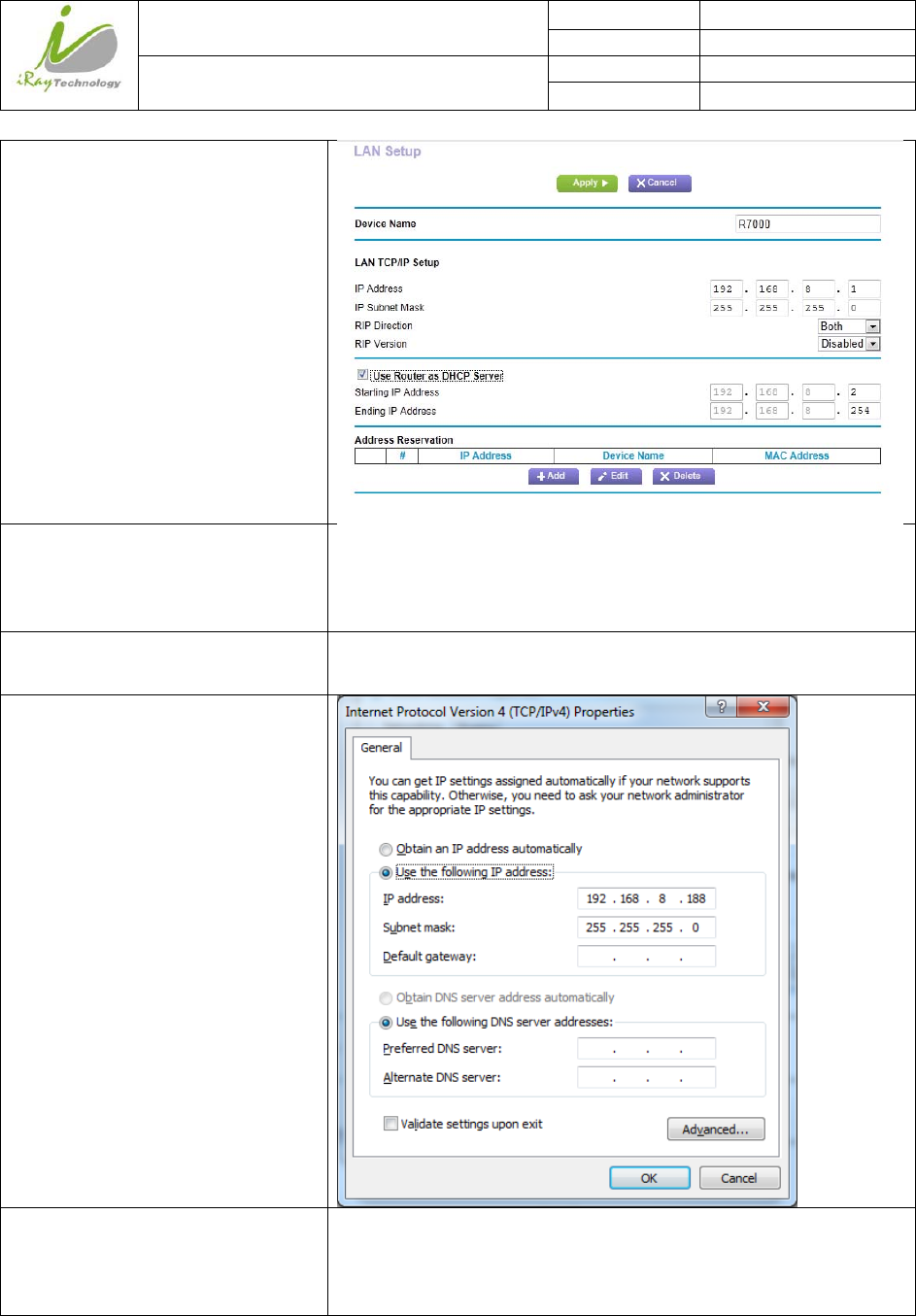
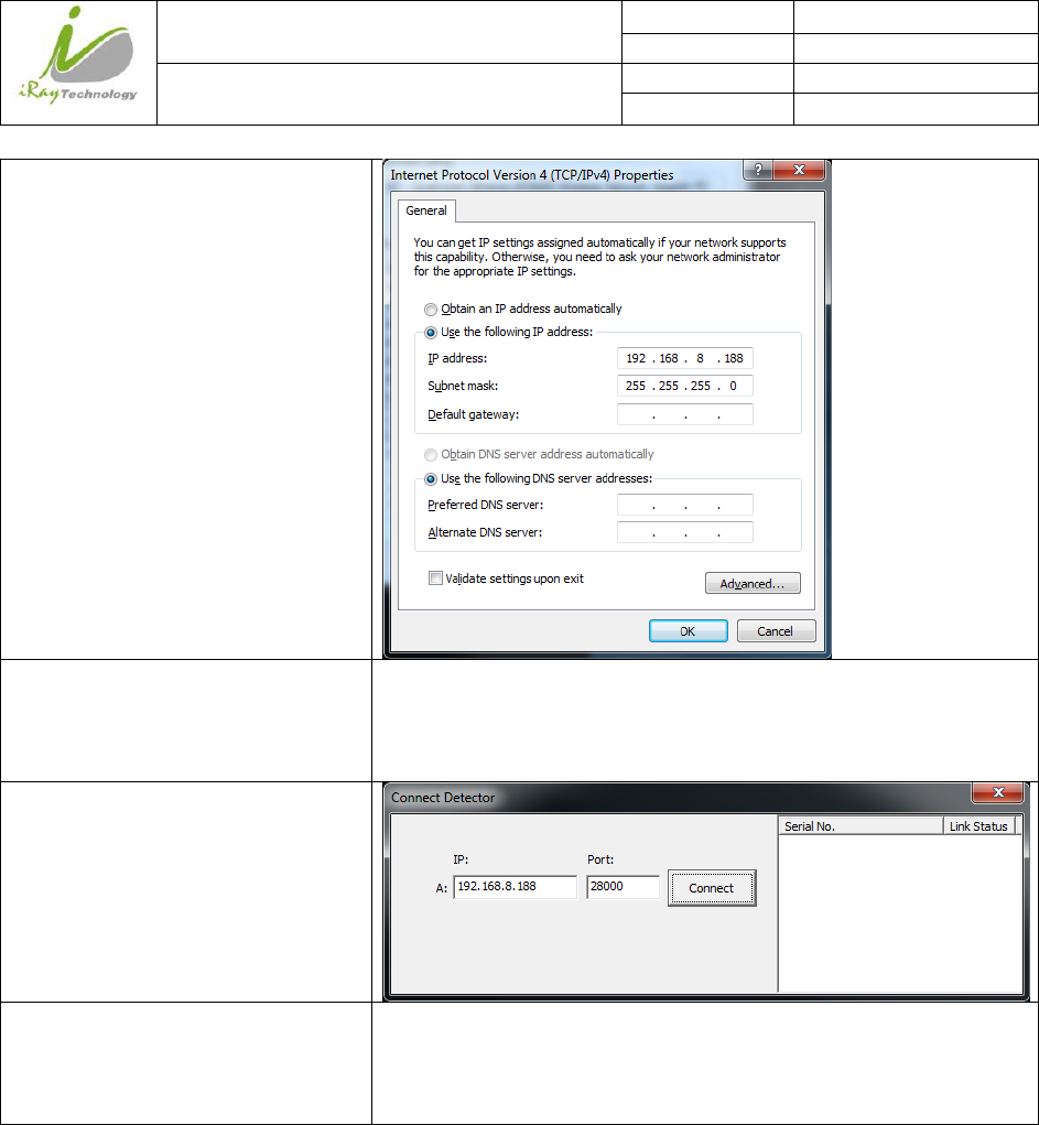
open IPV4 setting
IP setting
Network mask setting
IP address: 192.168.8.188
Subnet mask: 255.255.255.0
Open SDK and start connection
IP and port setting IP: 192.168.8.188
Port: 28000
3.4.1.2 Wireless Client mode
To complete Wireless Client mode configuration, users have to finish actions listed below.
Configuration of External wireless AP
Connect one end of Gigabit Ethernet
Cable to PC,Connect another end to
LAN port of External wireless AP
/
iRay Technology (Shanghai) Ltd. Doc N0. 037‐201‐02
Version A1
Mars1717VUser’sManual Date 2015.11.06
Page 47/141
Page 47
Open Network configuration
Open Local network configuration
iRay Technology (Shanghai) Ltd. Doc N0. 037‐201‐02
Version A1
Mars1717VUser’sManual Date 2015.11.06
Page 48/141
Page 48
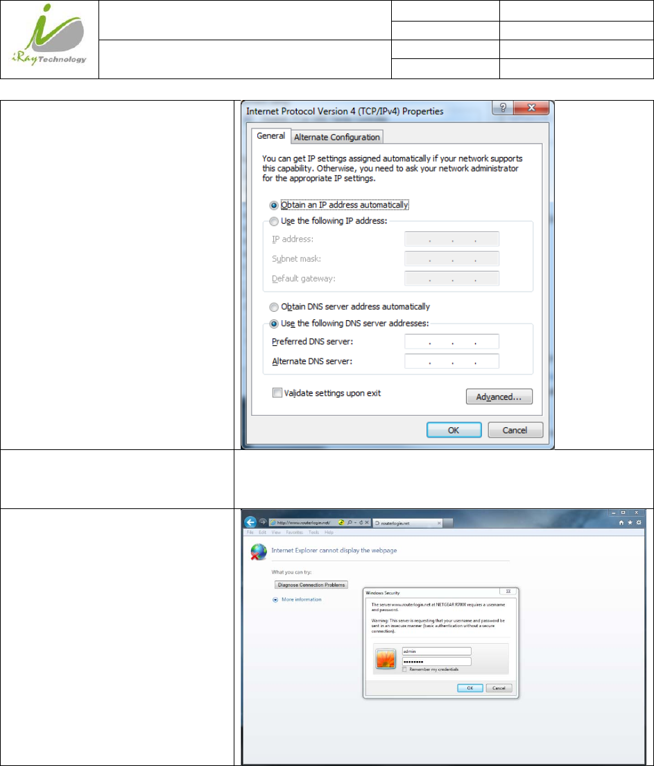
open IPV4 setting
IP setting
Network mask setting
Select “Obtain an IP address automatically”
Open browser and type 192.168.1.1
Log into external wireless AP
iRay Technology (Shanghai) Ltd. Doc N0. 037‐201‐02
Version A1
Mars1717VUser’sManual Date 2015.11.06
Page 49/141
Page 49
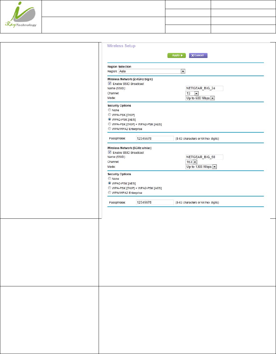
Wireless setup
Configure 2.4GHz wireless network
SSID: NETGEAR_BIG_24
Security: WPA2-PSK
Password: 12345678
Channel: [Please check the current Wi-Fi environment, and choose a
relatively clean channel]
Configure 5GHz wireless network
SSID: NETGEAR_BIG_50
Security: WPA2-PSK
Password: 12345678
Channel: [Please check the current Wi-Fi environment, and choose a
relatively clean channel]
iRay Technology (Shanghai) Ltd. Doc N0. 037‐201‐02
Version A1
Mars1717VUser’sManual Date 2015.11.06
Page 50/141
Page 50
LAN setup
Configure LAN IP address IP address: 192.168.8.1
Subnet Mask: 255.255.255.0
External Wireless AP Reboot Apply above settings and reboot your wireless router.
Recover Local Network IPv4 setting of
PC wired Ethernet interface
IP setting
Network mask setting
IP address: 192.168.8.188
Subnet mask: 255.255.255.0
Configuration of detector
Either Wired Cable or Infrared device can be used to configure detector in wireless client mode.
iRay Technology (Shanghai) Ltd. Doc N0. 037‐201‐02
Version A1
Mars1717VUser’sManual Date 2015.11.06
Page 51/141
Page 51
a.To start configuration with wired cable. It is necessary to finish 3.2.2.1, then proceed to the steps below.
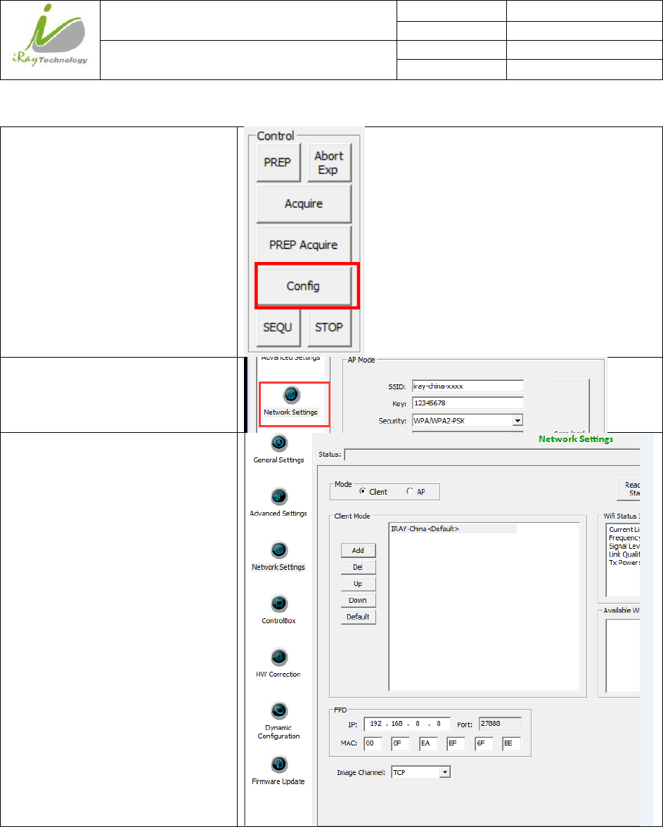
Click “Configure” in IDemo
Click “Network setting”
Click “Add”
iRay Technology (Shanghai) Ltd. Doc N0. 037‐201‐02
Version A1
Mars1717VUser’sManual Date 2015.11.06
Page 52/141
Page 52
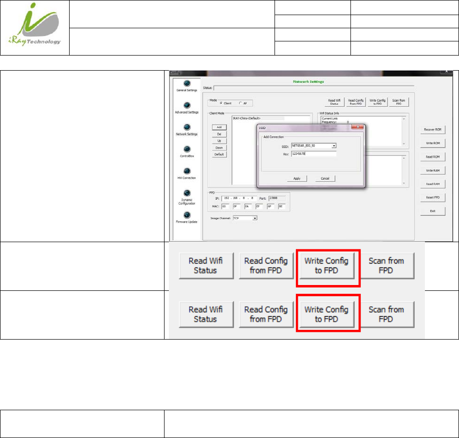
Change SSID and Key,
Click “Apply”
Click “write Config to FPD”
Do not remove wired cable until “write
to FPD” button recovers
Since we have chosen default SSID and password, it would connect to wireless AP immediately after powered on
next time.
B. To start Infrared configuration. Please see below
Connect Infrared device with
Workstation
/
iRay Technology (Shanghai) Ltd. Doc N0. 037‐201‐02
Version A1
Mars1717VUser’sManual Date 2015.11.06
Page 53/141
Page 53
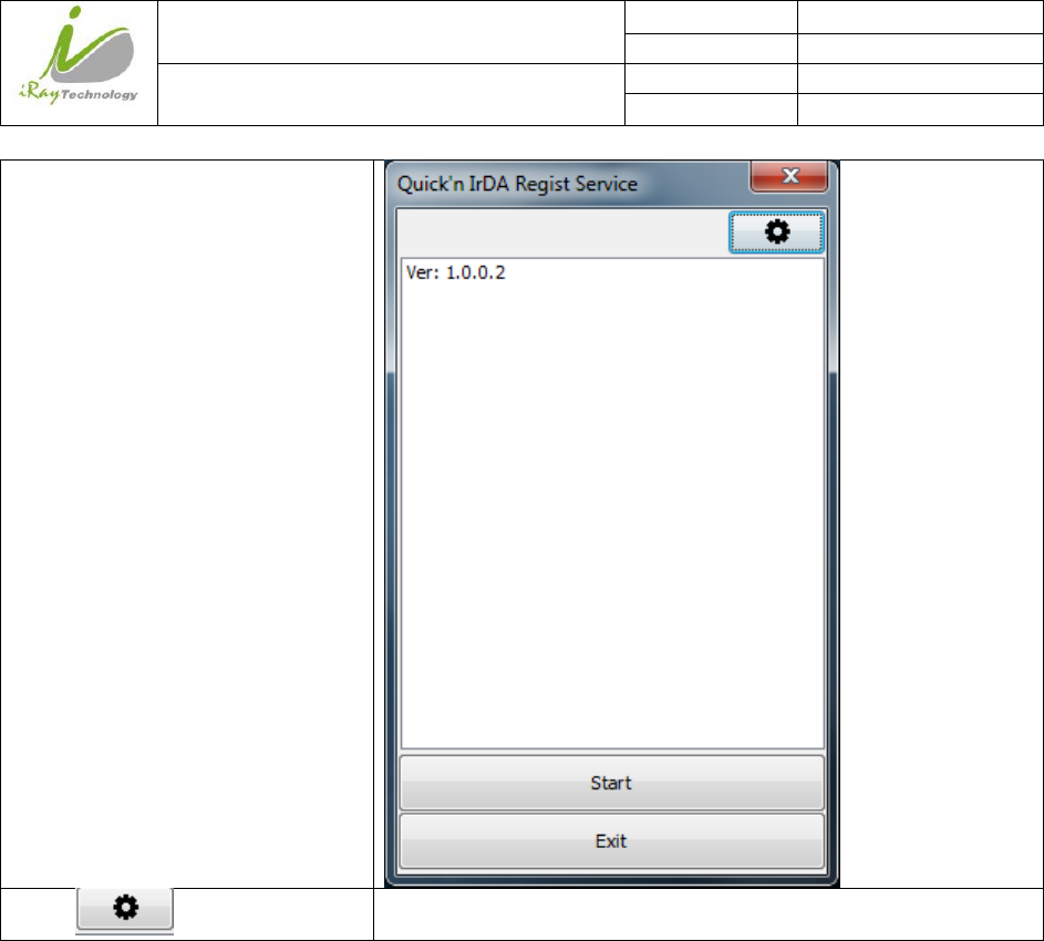
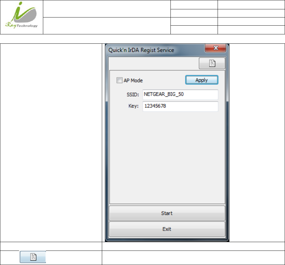
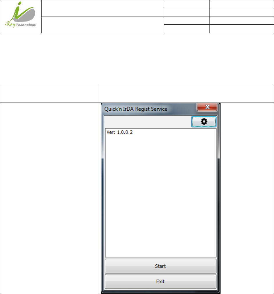
Start IrDARegister.exe
Click “ ” to open wifi setting
/
iRay Technology (Shanghai) Ltd. Doc N0. 037‐201‐02
Version A1
Mars1717VUser’sManual Date 2015.11.06
Page 54/141
Page 54
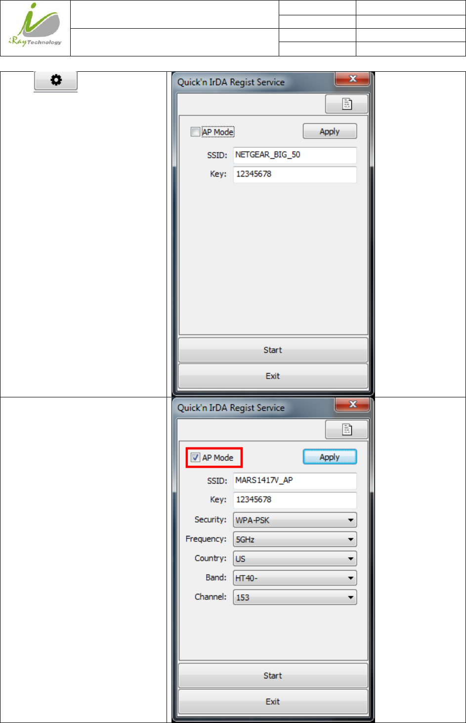
Change SSID and password,do not
select AP mode
Click “Apply” /
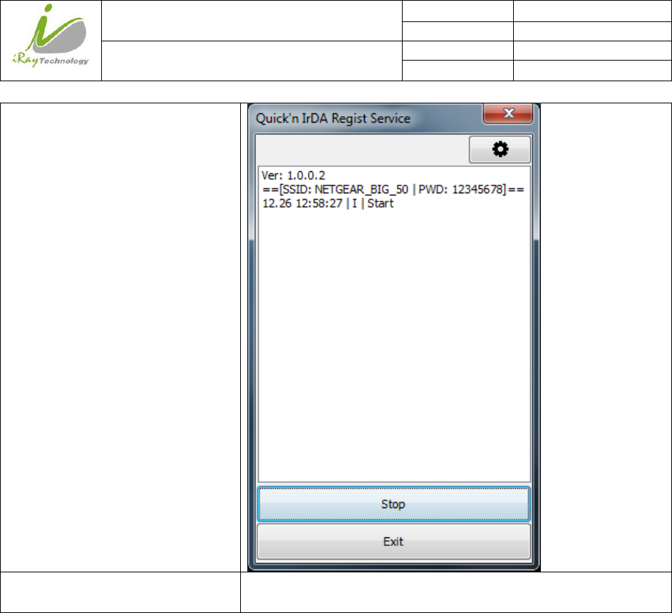
Click” ”
/
iRay Technology (Shanghai) Ltd. Doc N0. 037‐201‐02
Version A1
Mars1717VUser’sManual Date 2015.11.06
Page 55/141
Page 55
Click”Start”
Point Infrared device to detector’s
infrared interface
/
iRay Technology (Shanghai) Ltd. Doc N0. 037‐201‐02
Version A1
Mars1717VUser’sManual Date 2015.11.06
Page 56/141
Page 56
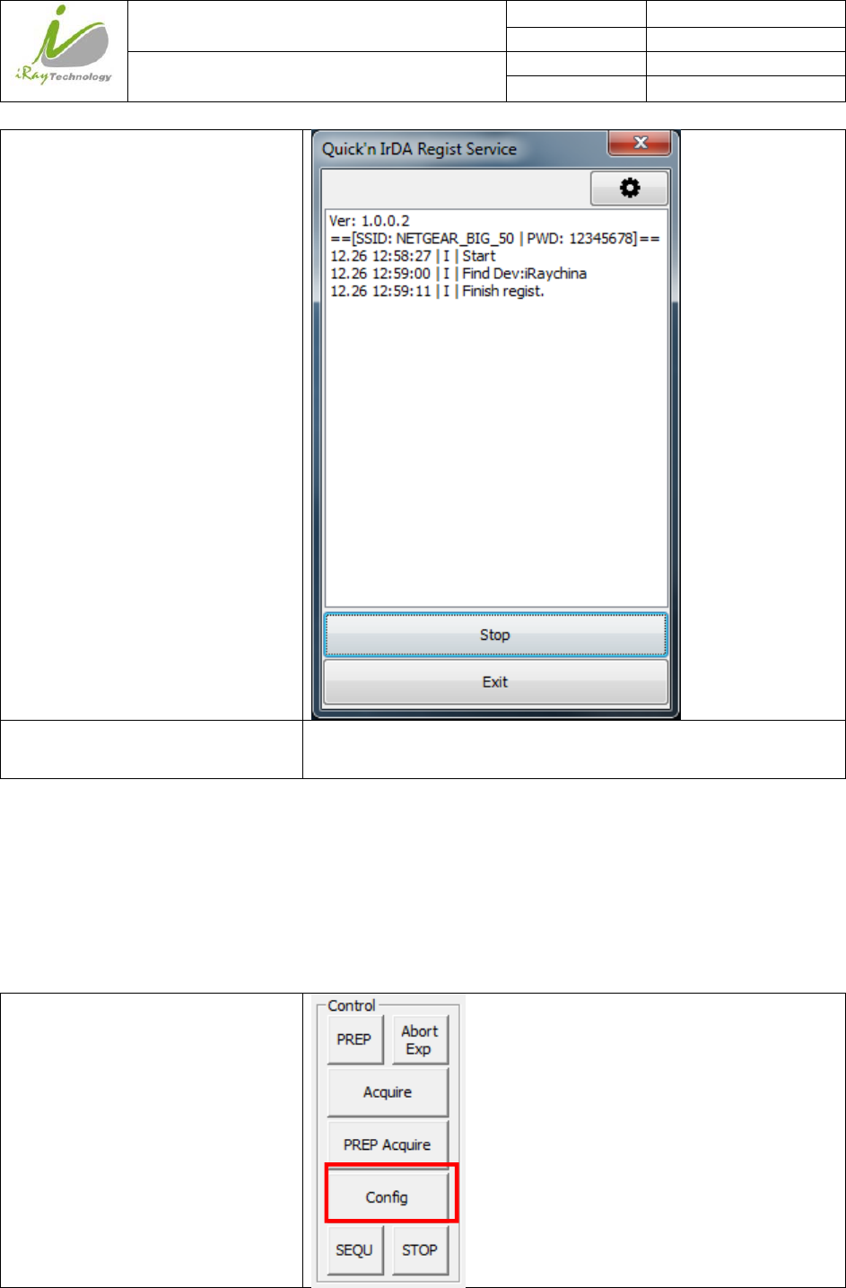
Do not click”Exit” until success
Disconnect Infrared device from PC /
3.4.1.3 Wireless AP mode
To complete Wired connection configuration, user has to finish actions listed below.
Configuration of detector
Either Wired cable or Infrared device can be used to configure detector wireless AP mode.
a.To start wired cable configuration, users should finish 3.4.1.1, then proceed to the steps below.
Click “Configure” in IDemo
iRay Technology (Shanghai) Ltd. Doc N0. 037‐201‐02
Version A1
Mars1717VUser’sManual Date 2015.11.06
Page 57/141
Page 57
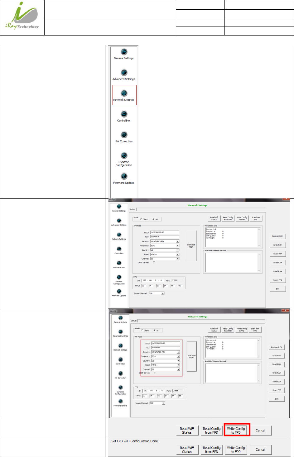
Click “Network setting”
Select AP mode
Change SSID and password setting
Click “write Config to FPD”
Do not remove wired cable until “write
to FPD” button recovers
iRay Technology (Shanghai) Ltd. Doc N0. 037‐201‐02
Version A1
Mars1717VUser’sManual Date 2015.11.06
Page 58/141
Page 58
Since we have chosen default SSID and password, it would connect to wireless AP immediately after powered on
next time.
b.To start Infrared configuration, please see below
Connect Infrared device with PC /
Start IrDARegister.exe
iRay Technology (Shanghai) Ltd. Doc N0. 037‐201‐02
Version A1
Mars1717VUser’sManual Date 2015.11.06
Page 59/141
Page 59
Click “ ” to open wifi setting
Select “AP mode”
iRay Technology (Shanghai) Ltd. Doc N0. 037‐201‐02
Version A1
Mars1717VUser’sManual Date 2015.11.06
Page 60/141
Page 60
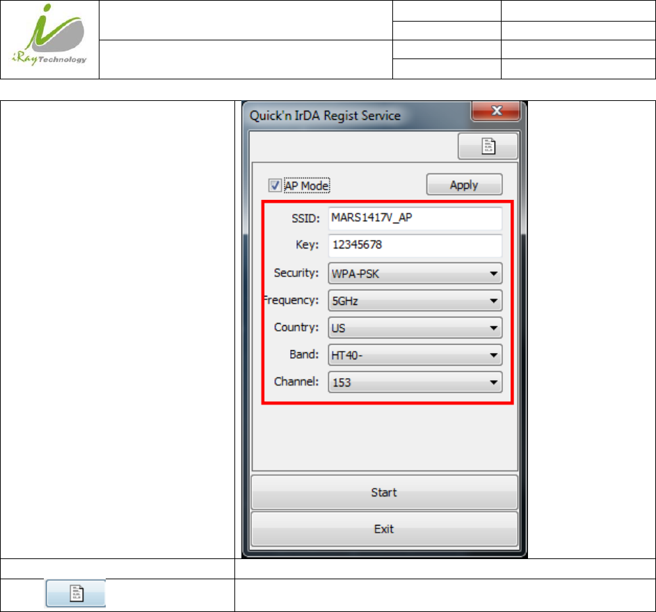
Change SSID and password and other
parameter
Click “Apply” /
Click” ”
/

iRay Technology (Shanghai) Ltd. Doc N0. 037‐201‐02
Version A1
Mars1717VUser’sManual Date 2015.11.06
Page 61/141
Page 61
Click”Start”
Do not click”Exit” until success
iRay Technology (Shanghai) Ltd. Doc N0. 037‐201‐02
Version A1
Mars1717VUser’sManual Date 2015.11.06
Page 62/141
Page 62
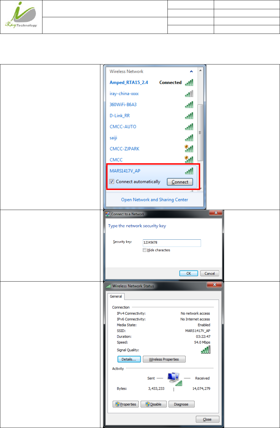
Configuration of external wireless card
Open Wireless signal List
Select SSID which belongs to
Detectors, input password and log into
system
Open wireless card configuration
iRay Technology (Shanghai) Ltd. Doc N0. 037‐201‐02
Version A1
Mars1717VUser’sManual Date 2015.11.06
Page 63/141
Page 63
open IPV4 setting
IP setting
Network mask setting
IP address: 192.168.8.188
Subnet mask: 255.255.255.0
Open SDK and start connection
IP and port setting IP: 192.168.8.188
Port: 28000
iRay Technology (Shanghai) Ltd. Doc N0. 037‐201‐02
Version A1
Mars1717VUser’sManual Date 2015.11.06
Page 64/141
Page 64
4 Operation
Mars1717V provides SDK for users to integrate detector into their DR system. Additionally, it also provides
an application for demonstration, i.e. Idemo. User can use Idemo to control detector without DR system.
4.1 Main Operation
To Acquire X-ray image is the main operation of Mars1717V. Most importantly, detector should build
synchronization with X-ray generator.Mars1717V is born with two ways to acquire X-ray image, that is
Software Mode, Inner Mode and Isync Plus Mode.
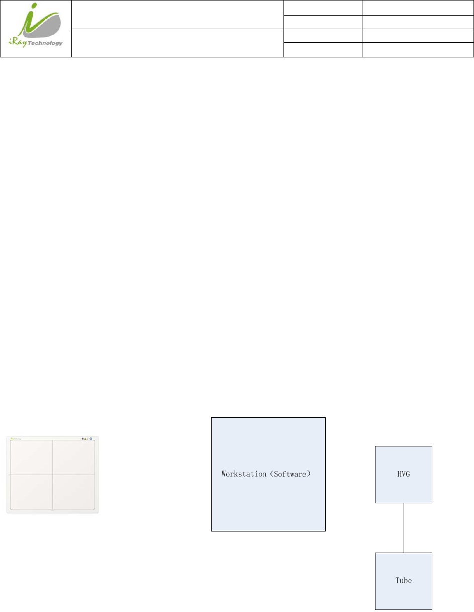
4.1.1 Software Mode
4.1.1.1 Block Diagram
Software mode is the basic way to acquire X-ray image. Please see figure below for general feature
Workstation is a host PC device installed with idemo and SDK. Chapter 3.1 has described how to establish
connection between detectors and workstation. In software mode, workstation does not have to control X-ray
generator. Users would decide when to shoot X-ray.
iRay Technology (Shanghai) Ltd. Doc N0. 037‐201‐02
Version A1
Mars1717VUser’sManual Date 2015.11.06
Page 65/141
Page 65
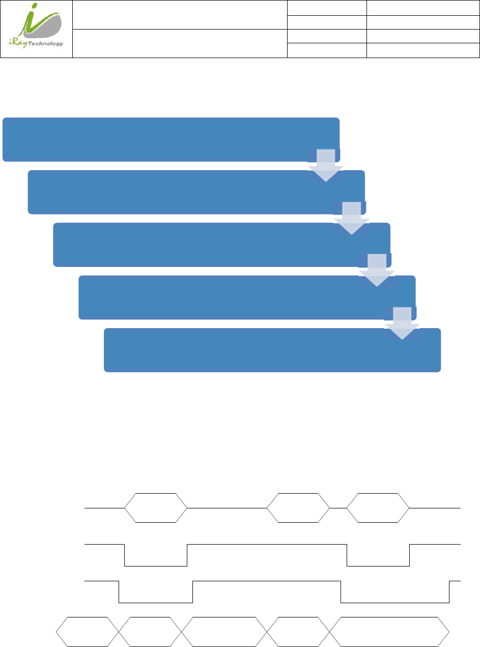
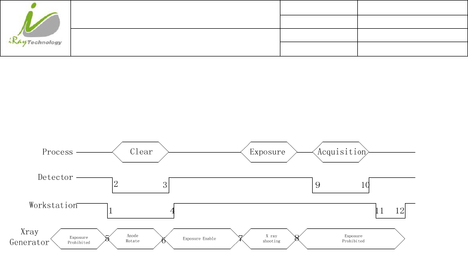
4.1.1.2 Work flow
4.1.1.3 Timing Setting
To set a clear scenario for program, see diagram below for details
Clear Exposure Acquisition
Detector
Anode
Rotate Exposure Enable X ray
shooting
Exposure
Prohibited
Workstation
Xray
Generator
Process
Exposure
Prohibited
1
23
4
5678
9
10 11
12
1. Workstation receives “prep” request, send command “Clear” to panel.
Click “Prep”
Panel preparation,Wait until the warning message change from “Exposure
Prohibit” to “Exposure Enable”
Shoot X-ray at any time. However the longer time you wait. The worse
image would be. So please shoot once X-ray generator is ready.
After shooting, Click”Acquire”
Wait for image uploaded

iRay Technology (Shanghai) Ltd. Doc N0. 037‐201‐02
Version A1
Mars1717VUser’sManual Date 2015.11.06
Page 66/141
Page 66
2. Panel receives “clear” from workstation, start detector internal clear cycle. At the same time, detector
would tell workstation “Exposure Prohibited”.
3. Detector finished ”Clear” action and send a message reminding “Exposure Enable”
4. Workstation shows “Exposure Enable” on the iDemo’s message bar to tell user shoot X-ray now.
5. User triggers X-ray generator to initialize and do anode rotation to prepare for X-ray shooting.
6. X-ray generator finishes preparation for X-ray shooting and reminds user to shoot.
7. X-ray generator starts releasing X-ray
8. X-ray generator finishes X-ray shooting.
9. Workstation receives “Acquire” request, send command “Data Acquisition” to panel.
10. Panel receives “Data Acquisition” from workstation, start data acquisition operation.
11. Panel completes image acquisition and begins to send data to workstation.
12. Workstation receives all image data from panel.
If Hardware Pre-offset and Hardware calibration is selected, image is the final image.
If Software Pre-offset and Software Calibration is selected, image would be the raw image, workstation
would finish image processing work and show on screen.
If Hardware Post offset and Hardware calibration is selected, image got would be preview image (2x2
binning). After step12, panel would do another dark image acquisition. With both light image and dark
image, panel completes all the correction and calibration process. Finally, panel uploads processed image to
workstation.
If Software Post offset and Software calibration is selected, image got would be preview image (No binning).
After step12, Workstation sends another “clear Acquire” command to panel, panel finishes a dark image
acquisition and uploads dark raw image to workstation. With both light image and dark image, workstation
completes all the correction and calibration process. Finally, corrected image shows on screen.
iRay Technology (Shanghai) Ltd. Doc N0. 037‐201‐02
Version A1
Mars1717VUser’sManual Date 2015.11.06
Page 67/141
Page 67
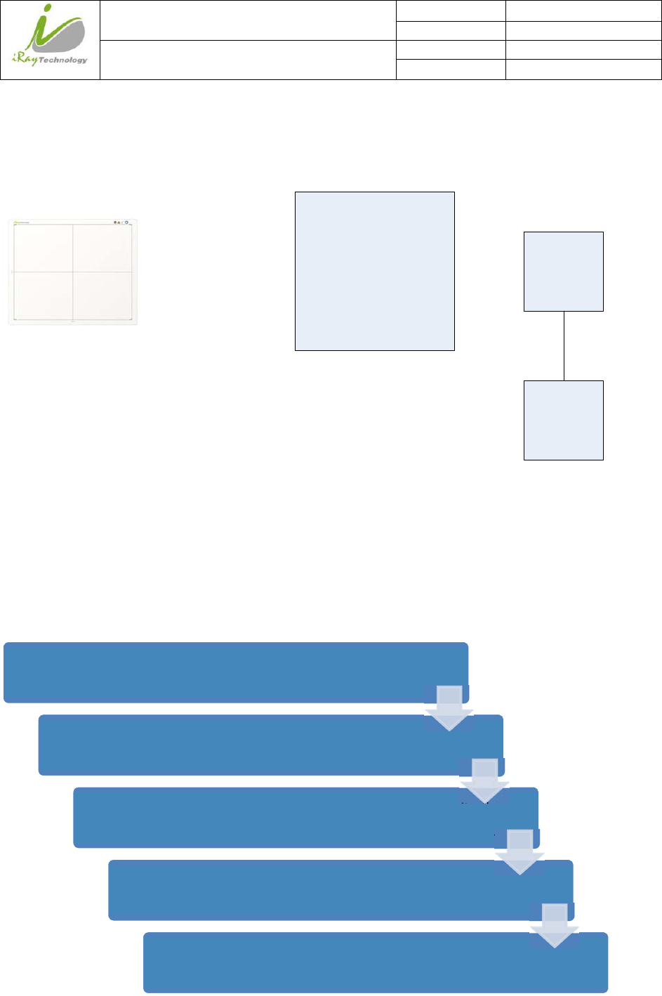
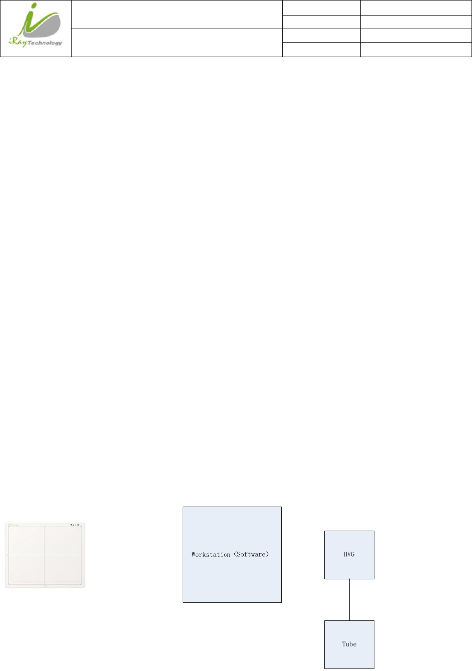
4.1.2 Inner Mode
4.1.2.1 Block Diagram
Workstation (Software ) HVG
Tube
Workstation is a host PC device installed with iDemo and SDK. Chapter 3 has described how to establish
connection between panels and workstation. In inner mode, workstation does not control X-ray generator.
Users would decide when to shoot X-ray.
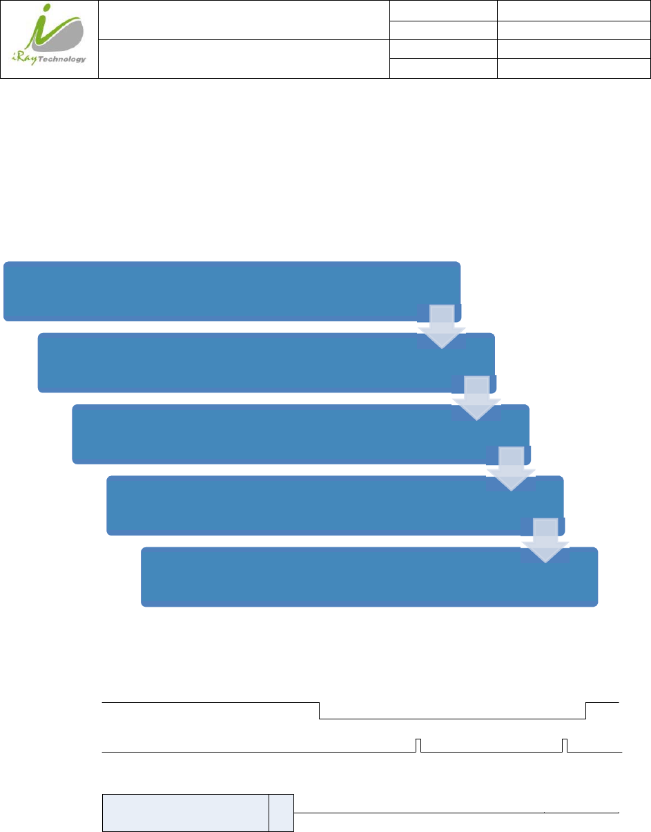
4.1.2.2 Work Flow
Click”Prepare”
Panelpreparation,Waitunitlthewarningmessagechangefrom“Exposure
Prohibit”to“ExposureEnable”
ShootX‐rayinexposurewindow.Howeverthelongertimeuserwaits,the
worseimagewouldbe.SopleaseshootingonceX‐raygeneratorisready.
Aftershooting,X‐rayinpanelwouldtriggerpaneltostartimage.
Waitforimageuploaded
iRay Technology (Shanghai) Ltd. Doc N0. 037‐201‐02
Version A1
Mars1717VUser’sManual Date 2015.11.06
Page 68/141
Page 68
4.1.2.3 Timing Setting
To set a clear scenario for program, see diagram below for details
1. Workstation receives “prep” request and sends “Clear” to panels.
2. Panel receives “clear” from Workstation, start clear operation. Meanwhile, panel would send “Exposure
Prohibited” to Workstation.
3. Panel finishes “Clear” operation and send “Exposure Enable” to Workstation.
4. Workstation shows “Exposure Enable” on the iDemo’s message bar to tell user shoot X-ray.
5. User triggers X-ray generator to initialize and do anode rotation to prepare for X-ray shooting
6. X-ray generator finishes preparation and reminds users.
7. X-ray generator begins releasing X-ray
8. X-ray generator finishes X-ray shooting.
9. X-ray sensor in panel triggers panel to start image acquisition operation.
10. Panel completes image acquisition and begins to send data to Workstation.
11. Workstation starts receiving image data from panel.
12. Workstation receives all image data from panel.
If Hardware Pre-offset and Hardware calibration is selected, image got is the final image.
If Software Pre-offet and Software Calibration is selected, image got would be raw image, workstation
would finish image processing work and show on screen.
If Hardware Post offset and Hardware calibration is selected, image got from detector would be preview
image (2x2 binning). After step12, Detector would do another dark image acquisition. With both light image
iRay Technology (Shanghai) Ltd. Doc N0. 037‐201‐02
Version A1
Mars1717VUser’sManual Date 2015.11.06
Page 69/141
Page 69
and dark image, detector completes all the correction process. Finally, detector uploads corrected image and
workstation shows on screen.
If Software Post offset and Software calibration is selected, image got from panel would be preview image
(No binning). After step12, Workstation sends another “clear Acquire” to panel, panel would do dark image
acquisition and uploads dark raw image to workstation. With both light image and dark image, workstation
completes all the correction process. Finally, corrected image shows on screen.
4.1.2.4 Abnormal Action
Action1: after Step4, if user wants to cancel this exposure cycle, Idemo provides an “Abort Exp” function to
close exposure windows. However, Idemo allows user to click “Abort Exp” until Workstation receives first
image.
Action2: after Step4, if user does not shoot X-ray in exposure windows, panel would close exposure
windows automatically and send a message to workstation that waiting for X-ray shooting is overtime.
Meanwhile, panel would also start image acquisition. After image acquisition, panel sends image to
workstation.
4.1.3 IsyncPlusMode
4.1.3.1 Block Diagram
iRay Technology (Shanghai) Ltd. Doc N0. 037‐201‐02
Version A1
Mars1717VUser’sManual Date 2015.11.06
Page 70/141
Page 70
Workstation is a host PC device installed with iDemo and SDK. Chapter 3 has described how to establish
connection between panel and Workstation. In Isync Plus mode, User doesn’t interact with Workstation.
After shooting, images would be shown on screen immediately.
4.1.3.2 Work Flow
4.1.3.3 Timing Setting
X ray
Generator
Anode Rotate X
Ray
Workstation
1
45
Panel
2
3
1. X-ray generator is ready for X-ray shooting and begins to release X-ray.
2. Workstation receives “Exposure Prohibited” from Panel.
3. Panel starts uploading Pre-dark image and Light image to Workstation for preview. If hardware offset is
selected, panel would do offset first, and then upload preview image (2X2 binning).
Check SDK to make sure panel is ready
Shoot X-ray
X-ray sensor in panel triggers panel to stop flushing the panel
After fixed time, panel starts image acquisition
Wait for image uploaded
iRay Technology (Shanghai) Ltd. Doc N0. 037‐201‐02
Version A1
Mars1717VUser’sManual Date 2015.11.06
Page 71/141
Page 71
4. Panel starts uploading Post-dark image to Workstation. If hardware offset is chosen, panel would do
correction and calibration first, then upload processed image to Workstation.
5. Workstation receives “Exposure Enable” from Panel.
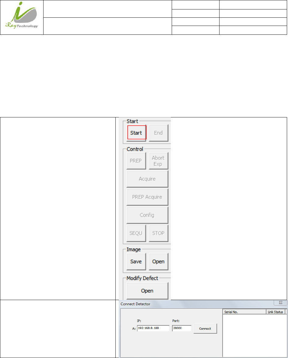
4.2 ConnectionBuild
Click “Start”
Input IP address and port number. The IP
address should be the same as the IP
address of the network card connected
with panel. The port should use the
default value of 28000;
Click “Connect”;
Note:
1. Once changing connection from different network card, user must re-connect panel with different IP
address.
2. Switching between wired and wireless connection does not need any extra operation.