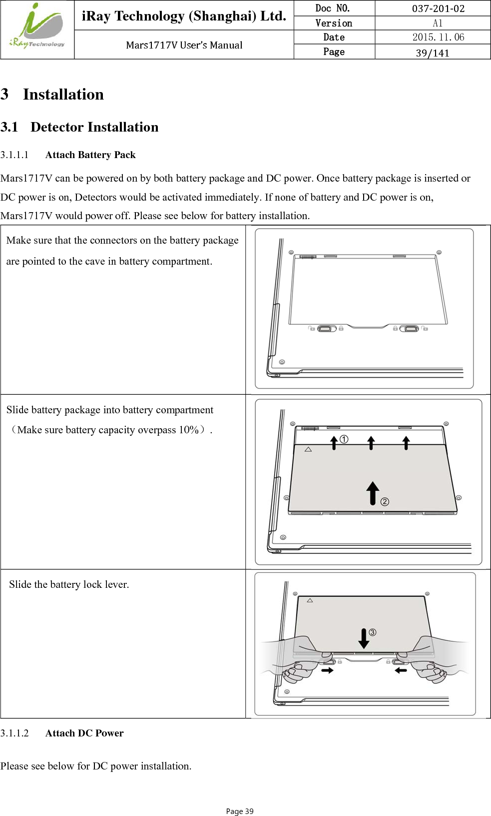
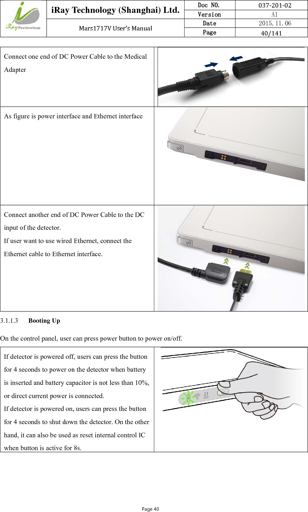
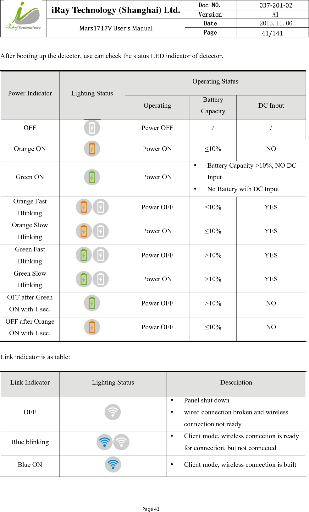
IRay Technology 02110113 Wireless Digital Flat Panel Detector User Manual 1
iRay Technology (Shanghai) Ltd. Wireless Digital Flat Panel Detector Users Manual 1
UserManual.wiki
>
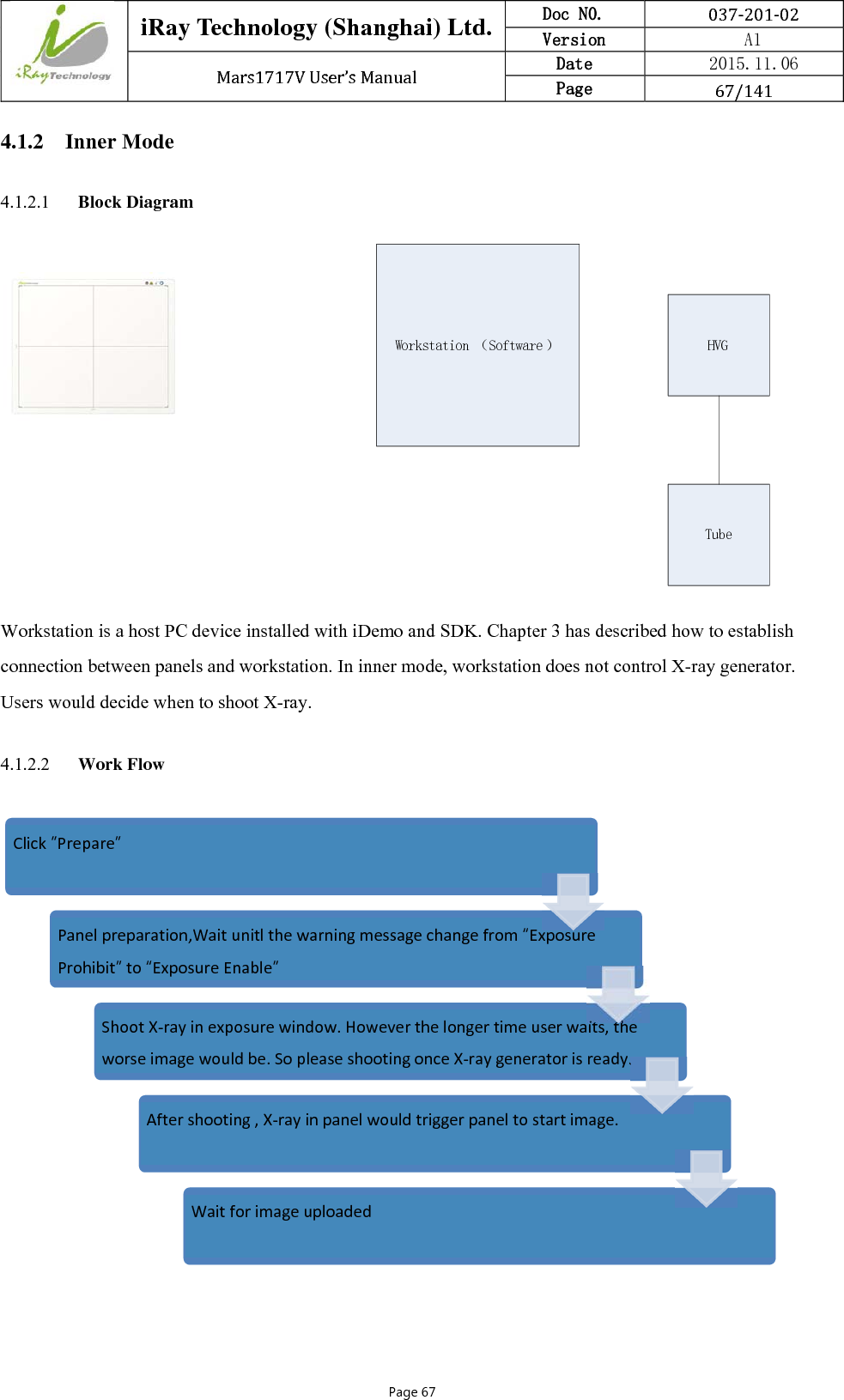
IRay Technology
>
02110113 User Manual
>
Users Manual-1
Contents
1.
User manual
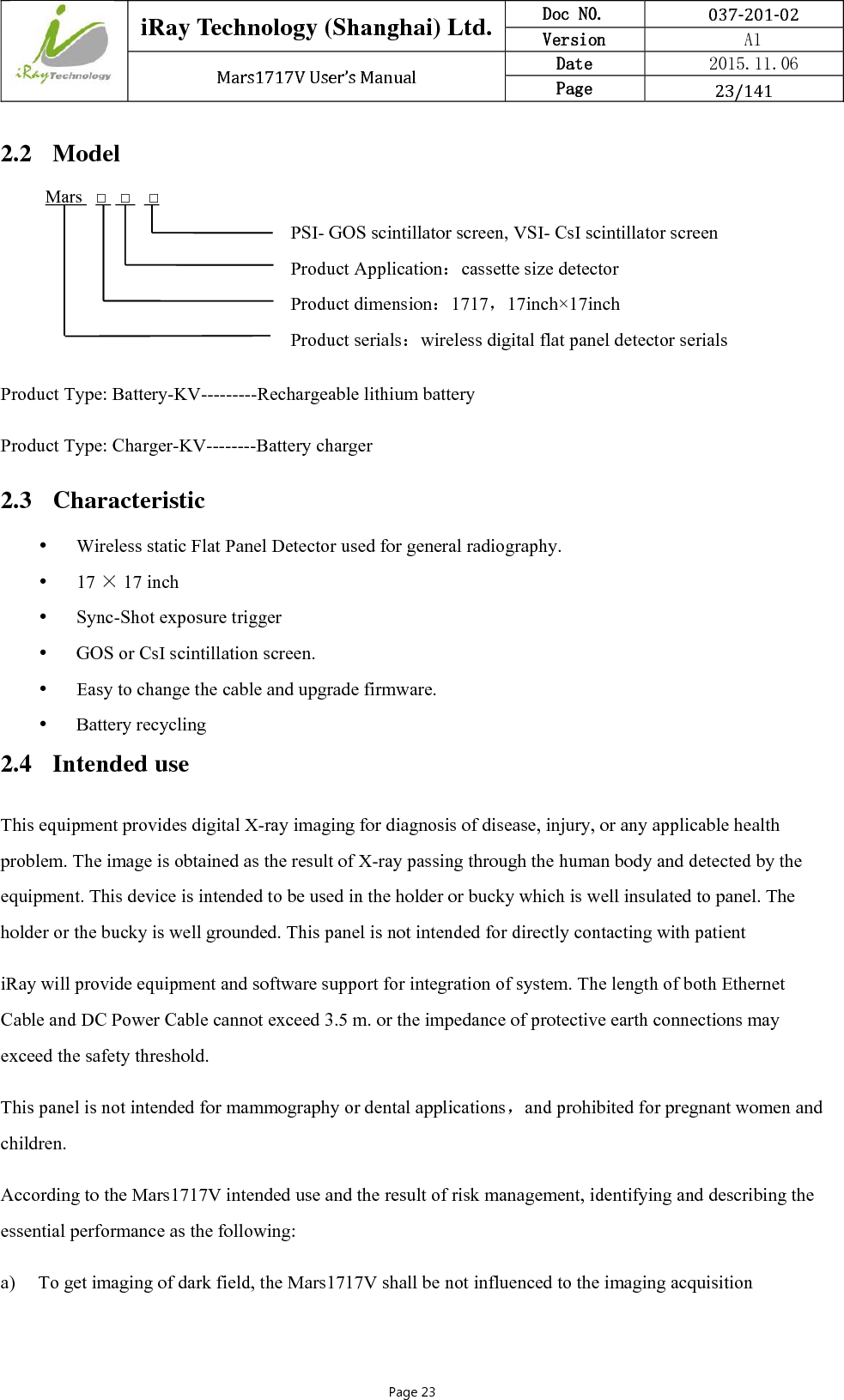
2.
Users Manual-1
3.
Users Manual-2
Users Manual-1
Navigation menu
Upload a User Manual
Namespaces
Wiki Guide
HTML
PDF
Info
Views
User Manual
Discussion / Help
Navigation
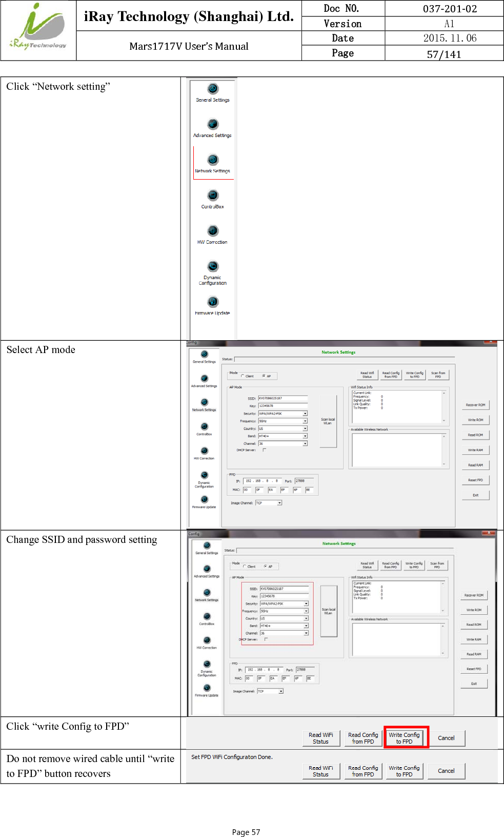
![iRay Technology (Shanghai) Ltd. Doc N0. 037‐201‐02 Version A1 Mars1717VUser’sManual Date 2015.11.06 Page 49/141Page 49 Wireless setup Configure 2.4GHz wireless network SSID: NETGEAR_BIG_24 Security: WPA2-PSK Password: 12345678 Channel: [Please check the current Wi-Fi environment, and choose a relatively clean channel] Configure 5GHz wireless network SSID: NETGEAR_BIG_50 Security: WPA2-PSK Password: 12345678 Channel: [Please check the current Wi-Fi environment, and choose a relatively clean channel]](https://usermanual.wiki/IRay-Technology/02110113.Users-Manual-1/User-Guide-2816526-Page-49.png)