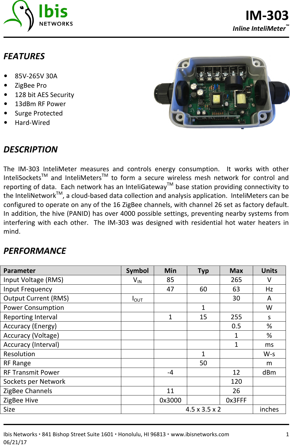
Ibis Networks 300 RF Engine Module User Manual DataSheet IM 301x

Ibis Networks Inc. RF Engine Module DataSheet IM 301x

User Manual

IM-301 InteliMeter™ Lighting Power-Pack   Ibis Networks ∙ 841 Bishop Street Suite 1601 ∙ Honolulu, HI 96813 ∙ www.ibisnetworks.com  1 06/21/17  FEATURES  • 85V-305V 20A  • ZigBee Pro • 128 bit AES Security • 13dBm RF Power • RoHS Compliant • Hard-Wired • Plenum Rated    DESCRIPTION  The  IM-301  Power-Pack  monitors  and  controls  energy  usage  for  lighting  or  other  electrical systems.  It works with InteliSocketsTM to form a secure wireless mesh network for control and reporting  of  data.    Each  network  is  anchored  by  an  InteliGatewayTM  base  station  providing connectivity to the InteliNetworkTM, a cloud-based data collection and analysis application.  The IM-301  provides  a low  voltage  24Vdc supply  for  motion  detectors  and  ambient  light  sensors, which can then control the operating state of the meter in either occupancy or vacancy mode (meeting  Title24 requirements).    A  wide  input voltage  range accommodates  120V, 240V, and 277V lighting systems.    PERFORMANCE  Parameter  Symbol  Min  Typ  Max  Units Input Voltage (RMS)  VIN 85    305  V Input Frequency    47  60  63  Hz Output Current (RMS)  IOUT     20  A Power Consumption      1.5    W Reporting Interval    1  15  255  s Accuracy (Energy)        0.5  % Accuracy (Voltage)        1  % Accuracy (Interval)        1  ms Resolution      1    W-s RF Range      50    m RF Transmit Power    -4    12  dBm ZigBee Channels    11    26   Size    3.5 x 3.5 x 1.5  inches
IM-301 InteliMeter™ Lighting Power-Pack   Ibis Networks ∙ 841 Bishop Street Suite 1601 ∙ Honolulu, HI 96813 ∙ www.ibisnetworks.com  2 06/21/17  COMPLIANCE  Agency  File UL916 – Energy Management Equipment  E470522 ZigBee Profile (Plover)  0x114B FCC  2AECN300  ENVIRONMENTAL  Parameter  Symbol  Min  Typ  Max  Units Operating Temperature  TO  0  25  40  C Storage Temperature  TS  -40    100  C Relative Humidity  RH  0    95  %  PUSHBUTTON / LED  Action  Result Press (no hold)  Toggle outlet state (on/off). Pressed while plugging in  Ignored.  Press and hold 3+ seconds  Soft reset.  Re-start socket.  Similar to plugging in.   Press and hold 8+ seconds  Hard reset.  All conditions are set to default.  Normally this sets socket back to FACTORY channel and hive.  However, if socket has been deployed on CUSTOMER channel and hive, a hard reset will then toggle between FACTORY and CUSTOMER settings.  This is a useful feature to correct a socket that has been accidentally reset to FACTORY.  It also provides a quick method to perform a manual self-heal.  If on FACTORY, LED will be red, CUSTOMER green.  Color  Meaning Black  Socket has no power. Yellow   Boot-up sequence in effect.  Typically ½ second duration. Flashing Red or Green  Socket is attempting to join mesh network. Red  Outlet is off. Green  Outlet is on.
IM-301 InteliMeter™ Lighting Power-Pack   Ibis Networks ∙ 841 Bishop Street Suite 1601 ∙ Honolulu, HI 96813 ∙ www.ibisnetworks.com  3 06/21/17  USAGE  The  IM-301  is  a  direct  replacement  for  your  existing  power-packs,  offering  a  quick  low-cost upgrade  for  your  lighting  system.    You  can  now  monitor  exact  power  consumption  for  each bank  of  lighting.    Each  InteliMeter  is  another  wireless  node  on  your  Ibis  mesh  along  with InteliSockets.    Set  lighting  schedules,  or  use  the  motion  detector  input  to  trigger  control  of other sockets.  The IM-301 is not limited to lighting and can be used for other purposes, such as control  of  existing  outlets  or  hard-wired  devices.    A  wide  input  voltage  range  and  20  amp capability opens up a world of possibilities.    WIRING  The IM-301 is designed to install as part of your electrical wiring infrastructure.  The enclosure mounts to a standard electrical box using a feed-thru  grommet,  keeping “hot” wires internal.  Class  2  secondary low  voltage  control  wires  are for  connecting  standard  motion  detectors  or ambient light sensors.  The external pushbutton and motion detector are both optional.
IM-301 InteliMeter™ Lighting Power-Pack   Ibis Networks ∙ 841 Bishop Street Suite 1601 ∙ Honolulu, HI 96813 ∙ www.ibisnetworks.com  4 06/21/17  FCC  This equipment has been tested and found to comply with the limits for a class B digital device, pursuant  to  part  15  of  the  FCC  rules.    These  limits  are  designed  to  provide  reasonable protection against harmful interference in a residential installation.  This equipment generates, uses, and can radiate radio frequency energy and if not installed and used in accordance with the instructions, may cause harmful interference to radio communications.  However, there is no guarantee that interference will not occur in a particular installation.  If this equipment does cause  harmful  interference  to  radio  or  television  reception,  which  can  be  determined  by turning the equipment off and on, the user is encouraged to try to correct the interference by one or more of the following measures:  • Reorient or relocate the receiving antenna. • Increase the separation between the equipment and receiver. • Connect  the  equipment  into  an  outlet  on  a  circuit  different  from  that  to  which  the receiver is connected. • Consult the dealer or an experienced radio/TV technician for help.  The  user  is  cautioned  that  changes  and  modifications  made  to  the  equipment  without  the approval of manufacturer could void the user’s authority to operate this equipment.   To  satisfy  RF  exposure  requirements,  this  device  and  its  antenna  must  operate  with  a separation distance of at least 20 cm from all persons and must not be co-located or operating in conjunction with any other antenna or transmitter.
IM-303 Inline InteliMeter™   Ibis Networks ∙ 841 Bishop Street Suite 1601 ∙ Honolulu, HI 96813 ∙ www.ibisnetworks.com  1 06/21/17  FEATURES  • 85V-265V 30A  • ZigBee Pro • 128 bit AES Security • 13dBm RF Power • Surge Protected • Hard-Wired    DESCRIPTION  The  IM-303  InteliMeter  measures  and  controls  energy  consumption.    It  works  with  other InteliSocketsTM  and  InteliMetersTM  to  form  a  secure  wireless  mesh  network  for  control  and reporting of data.  Each network has an InteliGatewayTM base station providing connectivity to the InteliNetworkTM, a cloud-based data collection and analysis application.  InteliMeters can be configured to operate on any of the 16 ZigBee channels, with channel 26 set as factory default.  In addition, the hive (PANID) has over 4000 possible settings, preventing nearby systems from interfering  with  each  other.    The  IM-303  was  designed  with  residential  hot  water  heaters  in mind.    PERFORMANCE  Parameter  Symbol  Min  Typ  Max  Units Input Voltage (RMS)  VIN 85    265  V Input Frequency    47  60  63  Hz Output Current (RMS)  IOUT     30  A Power Consumption      1    W Reporting Interval    1  15  255  s Accuracy (Energy)        0.5  % Accuracy (Voltage)        1  % Accuracy (Interval)        1  ms Resolution      1    W-s RF Range      50    m RF Transmit Power    -4    12  dBm Sockets per Network        120   ZigBee Channels    11    26   ZigBee Hive    0x3000    0x3FFF   Size    4.5 x 3.5 x 2  inches
IM-303 Inline InteliMeter™   Ibis Networks ∙ 841 Bishop Street Suite 1601 ∙ Honolulu, HI 96813 ∙ www.ibisnetworks.com  2 06/21/17  COMPLIANCE  Agency  File UL916 – Energy Management Equipment  E470522 ZigBee Profile (Plover)  0x114B FCC  2AECN300  ENVIRONMENTAL  Parameter  Symbol  Min  Typ  Max  Units Operating Temperature  TO  0  25  40  C Storage Temperature  TS  -40    100  C Relative Humidity  RH  0    95  %  PUSHBUTTON / LED  Action  Result Press (no hold)  Toggle outlet state (on/off). Pressed while plugging in  Ignored.  Press and hold 3+ seconds  Soft reset.  Re-start socket.  Similar to plugging in.   Press and hold 8+ seconds  Hard reset.  All conditions are set to default.  Normally this sets socket back to FACTORY channel and hive.  However, if socket has been deployed on CUSTOMER channel and hive, a hard reset will then toggle between FACTORY and CUSTOMER settings.  This is a useful feature to correct a socket that has been accidentally reset to FACTORY.  It also provides a quick method to perform a manual self-heal.  If on FACTORY, LED will be red, CUSTOMER green.  Color  Meaning Black  Socket has no power. Yellow   Boot-up sequence in effect.  Typically ½ second duration. Flashing Red or Green  Socket is attempting to join mesh network. Red  Outlet is off. Green  Outlet is on.
IM-303 Inline InteliMeter™   Ibis Networks ∙ 841 Bishop Street Suite 1601 ∙ Honolulu, HI 96813 ∙ www.ibisnetworks.com  3 06/21/17  WIRING  The IM-303 is designed to be hard-wired between the power feed and a standard 240V 30A hot water heater.  #10 wires connect to screw terminals, designated at RED (neutral), BLACK (hot) and bare or GREEN (earth).    FCC  This equipment has been tested and found to comply with the limits for a class B digital device, pursuant  to  part  15  of  the  FCC  rules.    These  limits  are  designed  to  provide  reasonable protection against harmful interference in a residential installation.  This equipment generates, uses, and can radiate radio frequency energy and if not installed and used in accordance with the instructions, may cause harmful interference to radio communications.  However, there is no guarantee that interference will not occur in a particular installation.  If this equipment does cause  harmful  interference  to  radio  or  television  reception,  which  can  be  determined  by turning the equipment off and on, the user is encouraged to try to correct the interference by one or more of the following measures:  • Reorient or relocate the receiving antenna. • Increase the separation between the equipment and receiver. • Connect  the  equipment  into  an  outlet  on  a  circuit  different  from  that  to  which  the receiver is connected. • Consult the dealer or an experienced radio/TV technician for help.  The  user  is  cautioned  that  changes  and  modifications  made  to  the  equipment  without  the approval of manufacturer could void the user’s authority to operate this equipment.   To  satisfy  RF  exposure  requirements,  this  device  and  its  antenna  must  operate  with  a separation distance of at least 20 cm from all persons and must not be co-located or operating in conjunction with any other antenna or transmitter.

Navigation menu