Identec Solutions ILR-IQ350SAT GPS-SAT User Manual
Identec Solutions AG GPS-SAT
UserManual.wiki
>
Identec Solutions
>
ILR IQ350SAT User Manual
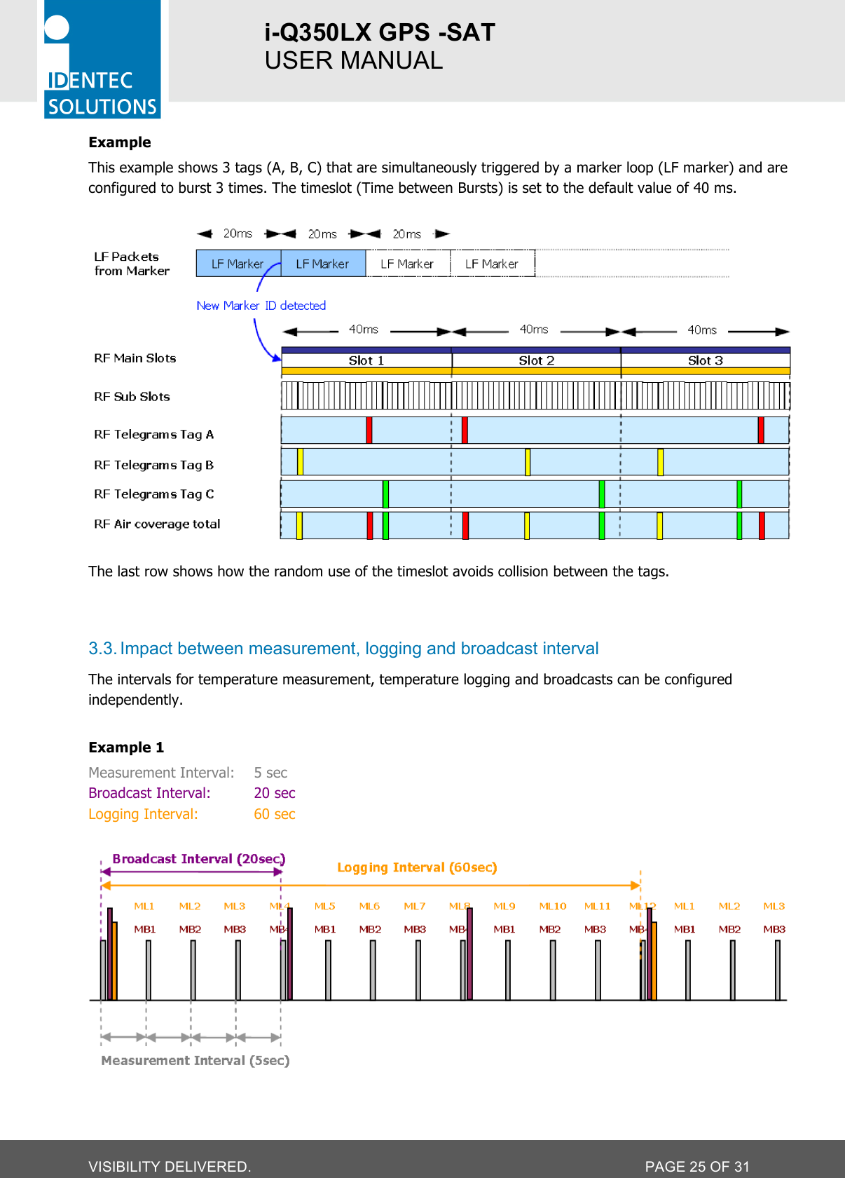
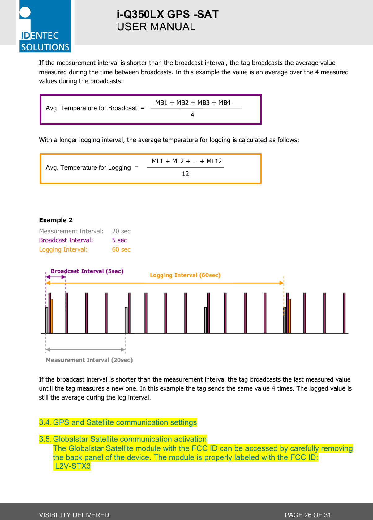
User manual
Navigation menu
Upload a User Manual
Namespaces
Wiki Guide
HTML
PDF
Info
Views
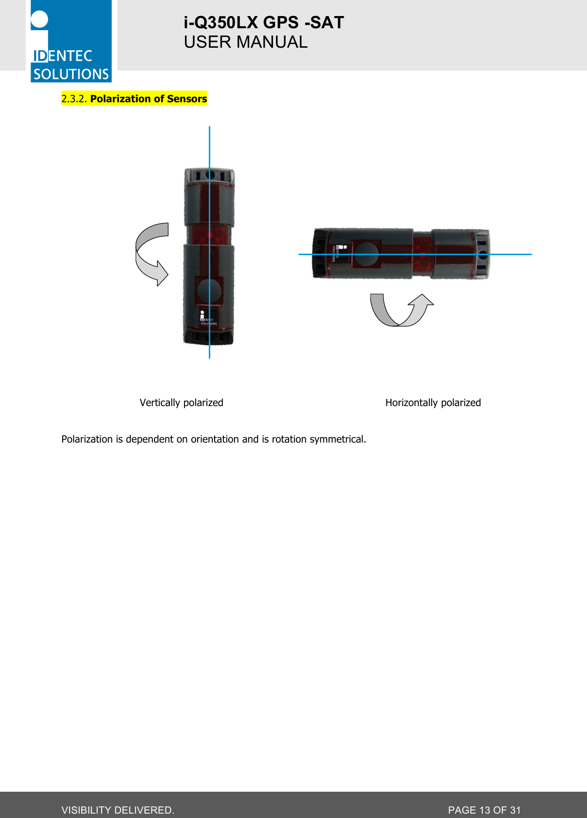
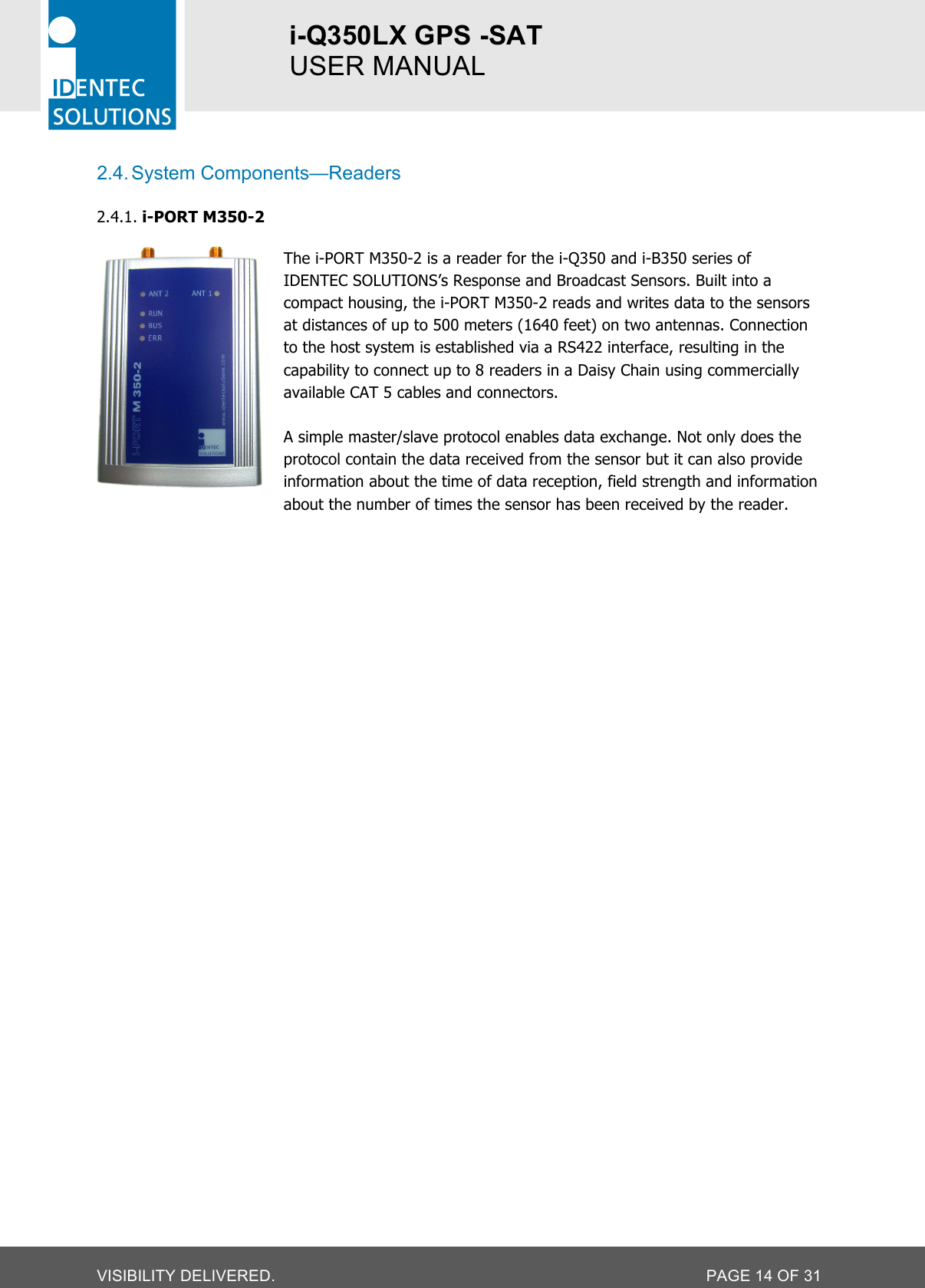
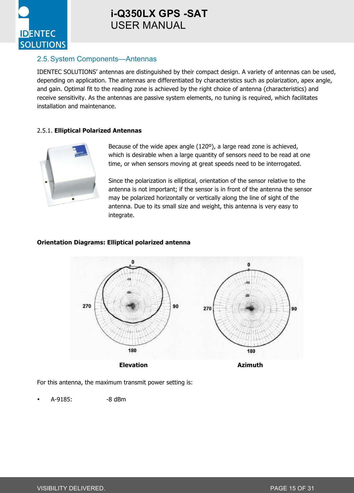
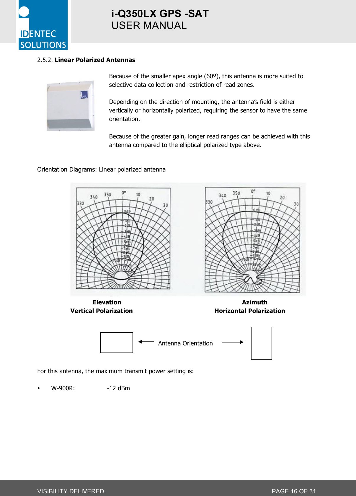
User Manual
Discussion / Help
Navigation