Identec Solutions ILR-IQ350SAT GPS-SAT User Manual
Identec Solutions AG GPS-SAT
User manual

VISIBILITY DELIVERED.
i-Q350LX GPS –SAT
SensorSMART™
Installation and Operation Manual
Preliminary

i-Q350LX GPS -SAT
USER MANUAL
VISIBILITY DELIVERED. PAGE 2 OF 31
Proprietary Notice
This document contains confidential information proprietary to IDENTEC SOLUTIONS and may not be used or
disclosed to other parties in whole or in part without the prior written authorization from IDENTEC
SOLUTIONS.
Disclaimer and Limitation of Liability
IDENTEC SOLUTIONS AG and its affiliates, subsidiaries, officers, directors, employees and agents do not make
any express or implied warranties or representations with respect to such information including, without
limitation, warranties as to non-infringement, reliability, suitability for a particular purpose and accuracy.
IDENTEC SOLUTIONS shall not under any circumstances be liable to any person for any special, incidental,
indirect or consequential damages, including without limitation, damages resulting from use of or reliance on
information presented herein, or loss of profits or revenues or costs of replacement goods, even if informed in
advance of the possibility of such damages.
Customer shall be solely responsible for proper selection, application, and use of Products, as well as the
incorporation/integration of Products into other equipment or systems. Customer shall indemnify and hold
IDENTEC SOLUTIONS harmless from and against any and all damages, liabilities, claims, or expenses
(including reasonable attorneys' fees) arising out of or relating to (i) improper selection, application,
installation, use or incorporation/integration of Products; or (ii) infringement of any patent, trademark,
copyright or other third party interest arising out of IDENTEC SOLUTIONS' compliance with any of Customer's
designs, specifications, or instructions.
Trademarks
“IDENTEC SOLUTIONS”, “Intelligent Long Range”, “ILR” and the stylized “i” are registered trademarks and “i-
CARD”, “i-PORT”, “i-LINKS”, “Visibility Delivered.” are trademarks of IDENTEC SOLUTIONS, Inc. and/or
IDENTEC SOLUTIONS AG.
Copyright Notice
Copyright © 2014 IDENTEC SOLUTIONS. All rights reserved.
No part of this document may be reproduced or transmitted in any form by any means, photographic,
electronic, mechanical or otherwise, or used in any information storage and retrieval system, without the prior
written permission of IDENTEC SOLUTIONS.
Issue 1.0 / July 2014
Subject to alteration without prior notice.
Printed in Austria
CONTACT US
EUROPE
HEAD OFFICE
USA
GERMANY
NORWAY
AUSTRALIA
+43 5577 87387-0
IDENTEC SOLUTIONS AG
IDENTEC SOLUTIONS, INC.
IDENTEC SOLUTIONS
IDENTEC SOLUTIONS AS
IDENTEC SOLUTIONS
sales@identecsolutions.com
Millennium Park 2
Preston Plaza
DEUTSCHLAND GMBH
Kartheia 3
AUSTRALIA AND
6890 Lustenau
17950 Preston Rd., Suite 200
AURUM 05 / Ost
4626 Kristiansand
NEW ZEALAND P/L
NORTH AMERICA
Austria
Dallas, Texas 75252
Goldbeckstraße 5
Norway
Riverview Business Park 72
+1 866 402-4211
Tel +43 5577 87387-0
USA
69493 Hirschberg
Tel +47 38 00 35 30
Maribyrnong St, Footscray VIC
sales@identecsolutions.com
Fax +43 5577 87387-15
Tel +1 972 535 4439
Germany
Fax +47 38 00 35 31
3011 Australia
Fax +1 469 424 0404
Tel +49 6201 99 57-0
Tel +61 3 9396 8900
Fax +49 6201 99 57-99
Fax +61 3 9689 2493
i-Q350LX GPS -SAT
USER MANUAL
VISIBILITY DELIVERED. PAGE 3 OF 31
Radio Frequency Compliance Statement
IDENTEC SOLUTIONS is the responsible party for the compliance of the following devices:
MODEL:
i-Q350LX GPS -SAT
Region/Country
Organization
Marking
EUROPE:
EC
CE
USA:
FCC
FCC ID OO4-ILR-IQ350SAT
Contains FCC ID: L2V-STX3
Canada:
Industry Canada
IC:3538A-IQ350SAT
The user(s) of these products are cautioned to only use accessories and peripherals approved, in advance, by
IDENTEC SOLUTIONS. The use of accessories and peripherals, other than those approved by IDENTEC
SOLUTIONS, or unauthorized changes to approved products, may void the compliance of these products and may
result in the loss of the user(s) authority to operate the equipment.
European Notification according R&TTE Directive
This equipment complies to Art. 6.4 of R&TTE Directive (2006/95/EU, 2004/108/EC, 1999/5/EC). It is tested for
compliance with the following standards: EN 300 220-1, ETSI EN 300 220-2, ETSI EN 301 489-1, ETSI EN 301
489-3, EN 60950-1:2006 + A11:2009 + A1:2010 + A12:2011
USA Notification
This device complies with part 15 of the FCC Rules. Operation is subject to the following two conditions:
(1) This device may not cause harmful interference, and
(2) this device must accept any interference received, including interference that may cause undesired
operation.
FEDERAL COMMUNICATIONS COMMISSION INTERFERENCE STATEMENT
This equipment has been tested and found to comply with the limits for a Class B digital device, pursuant to
part 15 of the FCC Rules. These limits are designed to provide reasonable protection against harmful
interference in a residential installation. This equipment generates, uses and can radiate radio frequency
energy and, if not installed and used in accordance with the instructions, may cause harmful interference to
radio communications. However, there is no guarantee that interference will not occur in a particular
installation. If this equipment does cause harmful interference to radio or television reception, which can be
determined by turning the equipment off and on, the user is encouraged to try to correct the interference by
one or more of the following measures:
-Reorient or relocate the receiving antenna.
-Increase the separation between the equipment and receiver.
-Connect the equipment into an outlet on a circuit different from that to which the receiver is connected.
-Consult the dealer or an experienced radio/ TV technician for help.

i-Q350LX GPS -SAT
USER MANUAL
VISIBILITY DELIVERED. PAGE 4 OF 31
CAUTION:
Any changes or modifications not expressly approved by the grantee of this device could void the user's
authority to operate the equipment.
Canada Certification
This device complies with Industry Canada licence-exempt RSS standard(s). Operation is subject to the
following two conditions:
(1) this device may not cause interference, and
(2) this device must accept any interference, including interference that may cause undesired operation of the
device
Le présent appareil est conforme aux CNR d‘Industrie Canada applicables aux appareils radio exempts de
licence. L‘exploitation est autorisée aux deux conditions suivantes:
(1) l‘appareil ne doit pas produire de brouillage, et
(2) l‘utilisateur de l‘appareil doit accepter tout brouillage radioélectrique subi, même si le brouillage est
susceptible d‘en compromettre le fonctionnement.
i-Q350LX GPS -SAT
USER MANUAL
VISIBILITY DELIVERED. PAGE 5 OF 31
ATEX Certification
Equipment or protected system intended for use in potentially explosive atmosphere directive 94/9/EC.
Compliance with the essential health and safety Requirements has been assured by compliance with the
following standards: EN 60079-0:2009, EN 60079-0:2006, EN60079-11:2007
IECEx Certification
The electrical apparatus and any acceptable variations to it specified in the schedule of this certificate and the
identified documents, was found to comply with the following standards: IEC 60079-0: 2004,
IEC 60079-0: 2007-10, IEC 60079-11: 2006
Special conditions for safe use – ATEX and IECEx
WARNING - Electrostatic Hazard:
Do not install in locations with increased electrostatic charge such as close to ventilations
systems or electric drives.
WARNING - Electrostatic Hazard: Clean plastic Tag surface only with a damp cloth. Do
not use solvents.
WARNING - This product should be installed by personnel trained in installation of
equipment in Hazardous Locations and meet the representative country’s National Electrical
Code.
EPS 13 ATEX ????
II 1 G
II 1G Ex ia T4 IIC Ga
II 1D Ex ia IIIC T135 °C Da
IECEx EPS ??
Type of Protection
Ex i
Marking
Ex ia T4 IIC Ga
Ex ia IIIC T135 °C Da
i-Q350LX GPS -SAT
USER MANUAL
VISIBILITY DELIVERED. PAGE 6 OF 31
This product contains components that are sensitive to electrostatic discharges. Please observe the special
instructions for their protection. Incorrect handling can damage the unit and cause the invalidation of the
warranty.
Minimum safety precautions against electrostatic discharge:
• Establish earth contact before you touch the unit. For example, touch the earthing screw on the unit.
Even better: Use an antistatic ribbon and earth yourself permanently for the time you handle the unit.
• Avoid unnecessary contact with the unit connectors and assemblies inside the unit.
• Only open the unit if the operational settings (as described in the manual) expressly require this.
• Use antistatic tools for the setting of the unit. (Warning: Do not touch life-threatening voltages with
these tools).
• Do not store unit and components without protective packaging.
• Only remove unit and components from the packaging immediately prior to installation.
These notes are not sufficient to guarantee complete protection from electrostatic discharges!
We recommend the use of suitable protective equipment.

i-Q350LX GPS -SAT
USER MANUAL
VISIBILITY DELIVERED. PAGE 7 OF 31
Contents
1.!PREFACE ....................................................................................................................... 10!
1.1.!PREPARATIONS ................................................................................................................. 10!
1.2.!SCOPE OF THIS DOCUMENT .................................................................................................. 10!
1.3.!RESPONSIBILITY ................................................................................................................ 10!
1.4.!UPDATES ......................................................................................................................... 10!
1.5.!SCOPE OF DELIVERY—VISUAL INSPECTION ............................................................................... 10!
1.6.!ASSOCIATED DOCUMENTS .................................................................................................... 10!
2.!INTRODUCTION ........................................................................................................... 11!
2.1.!FUNDAMENTALS ................................................................................................................ 11!
2.2.!COMPONENT OVERVIEW ...................................................................................................... 11!
2.3.!SYSTEM COMPONENTS—SENSORS .......................................................................................... 12!
2.3.1.!i-Q350 Tags ................................................................................................................ 12!
2.3.2.!Polarization of Sensors ................................................................................................ 13!
2.4.!SYSTEM COMPONENTS—READERS .......................................................................................... 14!
2.4.1.!i-PORT M350-2 ........................................................................................................... 14!
2.5.!SYSTEM COMPONENTS—ANTENNAS ........................................................................................ 15!
2.5.1.!Elliptical Polarized Antennas ......................................................................................... 15!
2.5.2.!Linear Polarized Antennas ............................................................................................ 16!
2.5.3.!1/2-Wave Whip Antenna .............................................................................................. 17!
2.5.4.!1-Wave Rod Antenna .................................................................................................. 18!
1!TAG MOUNTING TECHNIQUES ...................................................................................... 19!
1.1!DIMENSIONAL DRAWING ...................................................................................................... 19!
1.2!MOUNTING HOLE PATTERN .................................................................................................... 19!
1.3!MOUNTING TO CONTAINER .................................................................................................... 20!
1.4!SCREWS ........................................................................................................................... 21!
2.6.!TAG IDENTIFICATION .......................................................................................................... 22!
3.!INITIAL OPERATION, CONFIGURATION OF THE TAG .................................................. 23!
3.1.!GENERAL ......................................................................................................................... 23!
3.2.!PING RATE ...................................................................................................................... 24!
3.1.!LIMITATIONS OF THE USER DATA FIELD ................................................................................... 24!
3.2.!INFORMATION ON BURST SETTINGS ........................................................................................ 24!
3.3.!IMPACT BETWEEN MEASUREMENT, LOGGING AND BROADCAST INTERVAL ............................................ 25!
3.4.!GPS AND SATELLITE COMMUNICATION SETTINGS ....................................................................... 26!
3.5.!GLOBALSTAR SATELLITE COMMUNICATION ACTIVATION ................................................................ 26!
4.!MAINTENANCE ............................................................................................................. 28!
4.1.!GENERAL ......................................................................................................................... 28!
4.2.!REGULAR CLEANING OF THE SURFACE ..................................................................................... 28!
4.3.!PRECAUTIONARY MAINTENANCE ............................................................................................ 28!
4.4.!RETURNS ........................................................................................................................ 29!
5.!TECHNICAL DATA ......................................................................................................... 30!
SAFETY INSTRUCTIONS

i-Q350LX GPS -SAT
USER MANUAL
VISIBILITY DELIVERED. PAGE 8 OF 31
The system described in this manual is for exclusive operation of trained employees. Only qualified personnel
that have knowledge of the potential dangers involved should perform the installation, settings, maintenance
and repair of the units used.
Operational Safety
The correct and safe use of these systems assumes that operating and service personnel follow the safety
measures described in the manual alongside the generally acceptable safety procedures.
If there is a possibility that safe operations cannot be guaranteed, the system must be switched off, secured
against accidental use and the service unit responsible immediately informed.
Safety Documents
The i-Q350 tag was designed, tested and supplied in perfect condition according to document IEC348 Safety
Requirements for Electronic Units of Class 1.
Condensate / Change of Temperature
To avoid condensation in the system, the unit must be allowed to slowly adjust itself to warmer temperatures
after removal from cold and cool environments.
Do not open the housing
There is absolutely no need to open the systems housing during set up. Configuration is done with built in
interface wirelessly.
Earthing
Before establishing any connections the housing of the system must be earthed.
Battery Inside
All system tags contain a battery; therefore the following warning should be heeded:
WARNING - Fire, explosion and burn hazard risk of explosion if battery is replaced by an
incorrect type. Do not recharge, short circuit, crush, disassemble, heat above
100 °C (212 °F)
Do not incinerate, or expose contents to water
Fuses
Only experts who are aware of the dangers involved may replace the fuses. It must be ensured that only
fuses of the required current rating and the correct type are used for replacement. The use of repaired fuses
and/or short-circuiting the fuse holders is prohibited.

i-Q350LX GPS -SAT
USER MANUAL
VISIBILITY DELIVERED. PAGE 9 OF 31
Spare Parts
We recommend that only personnel, original products, spare and replacement parts authorized by IDENTEC
SOLUTIONS be used for installation, service and repair. IDENTEC SOLUTIONS does not accept any
responsibility for materials used, work carried out or possible consequences from unauthorized third party
vendors.
Electrostatic Discharge
Semi-conductors of the type MOS or CMOS as well as two-pin types and precision resistance are sensitive to
ESD. All components, printed circuit boards and auxiliary systems should therefore always be classed as
sensitive to electrostatic discharge.
Before opening the cover the unit should be placed onto an ESD-protected surface. As with all work on
modern electronic modules, the use of ESD clamps and ESD mats during work on the unit is recommended.
• Sufficiently protect all printed circuit boards that were removed from the unit from damage.
• Observe all normal precautions for the use of tools.
• Use ESD-protected packaging material.
Never use measuring units with low impedance for measuring or testing systems with semi-conductor
components. Never use high voltage testing units or dielectric test units to test systems with semi-conductor
components.
If it is necessary to check the isolating properties of the field wiring, the assemblies (electronic units and
sensors) should be disconnected.
Earth the test units.
IDENTEC SOLUTIONS does not accept the return of products where the regulations concerning the ESD
precautions and protective packaging materials were not followed.
ESD – Electrostatic Discharge
EMC – Electromagnetic Compatibility
SELV – Safety Extra Low Voltage – Protective measure against dangerous body currents, formerly: protective first voltage range

i-Q350LX GPS -SAT
USER MANUAL
VISIBILITY DELIVERED. PAGE 10 OF 31
1. PREFACE
1.1. Preparations
This installation manual must be read carefully prior to starting the installation. The described installation
works assume that installation materials like cable, antenna and data sensor holder, etc. are available.
1.2. Scope of This Document
This document is the hardware description of the i-Q350. This document is intended only for mechanical and
electrical installation of these central units.
1.3. Responsibility
IDENTEC SOLUTIONS reserves the right to make changes and updates to the content contained herein. It is
the user’s responsibility to contact the service department for any possible changes or updates to operating
and maintenance procedures.
1.4. Updates
Updates will be provided upon request. The information in this document may be subjected to changes
without prior notice.
1.5. Scope of Delivery—Visual Inspection
Check whether delivery is complete and for any damages. If the delivery is not complete or damaged
immediately inform the carrier. The dispatch and service organization of IDENTEC SOLUTIONS should also be
informed to facilitate the repair or exchange of the system.
1.6. Associated Documents
Software description and Programmer’s Guide
• SDK Online Help
• i-SHARE Manual
• Specific sensor manuals
i-Q350LX GPS -SAT
USER MANUAL
VISIBILITY DELIVERED. PAGE 11 OF 31
2. INTRODUCTION
2.1. Fundamentals
The IDENTEC SOLUTIONS’ SensorSMART Platform is the latest development in asset management,
localization and process optimization. Developed to deliver the last mile in industrial communication, the
SensorSMART Platform fulfills a niche not previously addressed by available networks.
The SensorSMART Platform takes the complexity out of managing assets, personnel safety monitoring and/or
the tracking of valuable cargo and the need for multiple technologies. The unique combination of active RFID,
RTLS and WSN in one platform eliminates the necessity for complex deployments of multiple technologies, or
the need to compromise with one technology’s specific functionalities. The pinnacle of the SensorSMART
Platform is that it captures the best of RFID, WSN, and RTLS while also avoiding the less desirable features of
each technology. Third party application development is also simplified for added flexibility.
2.2. Component Overview
!
!
!
!
!
i-Q350LX GPS -SAT
USER MANUAL
VISIBILITY DELIVERED. PAGE 12 OF 31
The SensorSMART Platform infrastructure features mobile readers (i-CARD), fixed readers (i-PORT) and
exciters (i-MARK). Network sensors offer the highest functionality within the SensorSMART Platform. Robust
and reliable, SMARTsensors monitor temperature, humidity, light, shock, tilt, motion, push button, digital
input, Hall sensor, etc.
The SDK (software development kit) is an easy to use framework that allows developers high level access
without requiring in depth knowledge of sensor or reader protocols, timing or implementations. Extracting,
filtering and sharing data as well as calculating an object’s position is only part of the i-SHARE (edgeware)
functionality.
i-APP is an intuitive web browser 2.0 application that allows for rapid application development for sensor
based applications. It is the SensorSMART Platform’s business intelligence.
2.3. System Components—Sensors
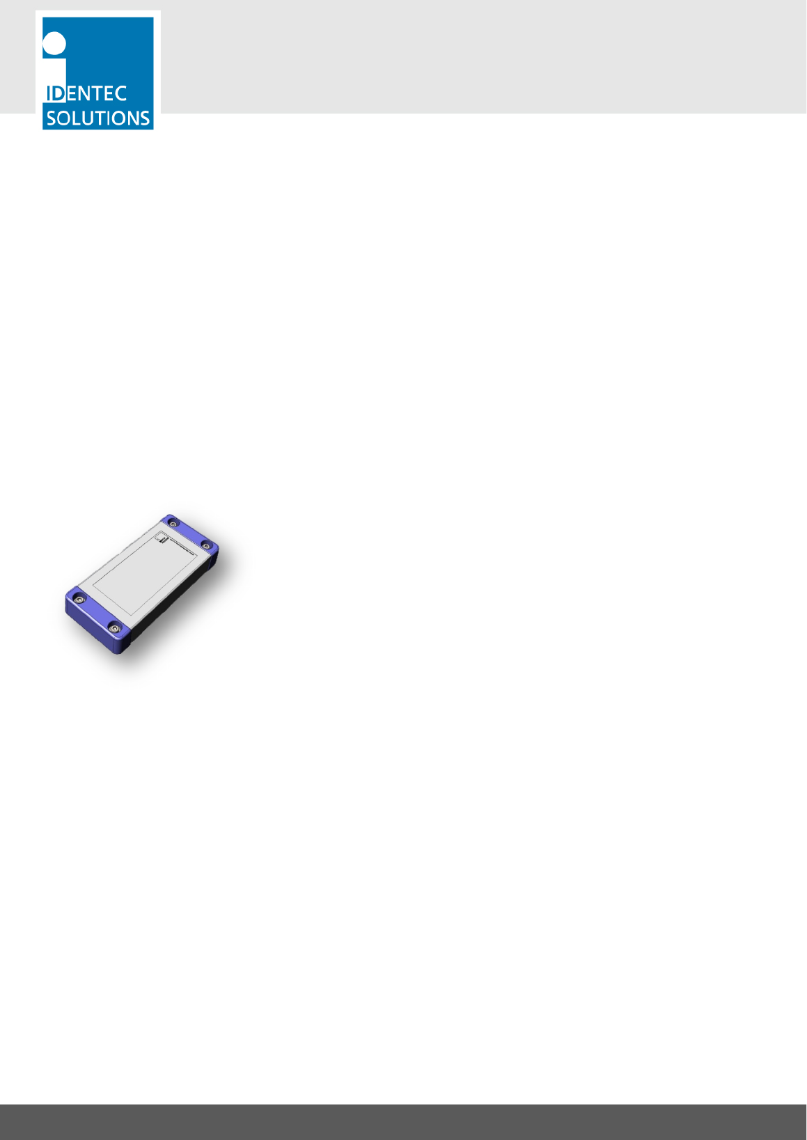
2.3.1. i-Q350 Tags
The ILR® i-Q350LX GPS –SAT active RFID tag with satellite navigation and
communication uplink provides highly accurate positioning of objects – even in
the most remote on- and off-shore locations. The combination of GPS, satellite
communication and active RFID sets a new benchmark in the oil and gas
industry
FEATURES
Designed to withstand the harshest and most demanding environments, the i-Q350 satellite tag is ideally
suited for applications such as CCU tracking and tracing or localization of high value assets and vehicles.
With its integrated GPS receiver and satellite modem, the tag can transmit its GPS position either via RFID or
via the globally available Globalstar satellite network.
The combination of low power components and a motion sensor enables a smart energy and cost
management. The tag only transmits position data when a change of the position is located. This allows an
outstanding battery lifetime and minimizes the operational costs to a minimum.
The integrated marker functionality allows to control if an object was moved through a particular zone or
gate. The inductive marker field triggers the Tag to send the location information to a reader with its RFID
capabilities.
The ATEX Zone 0 and IECEx certification allows usage of the tag in dangerous and potentially explosive
atmospheres and is therefore ideally suited to the oil and gas industry.
i-Q350LX GPS -SAT
USER MANUAL
VISIBILITY DELIVERED. PAGE 13 OF 31
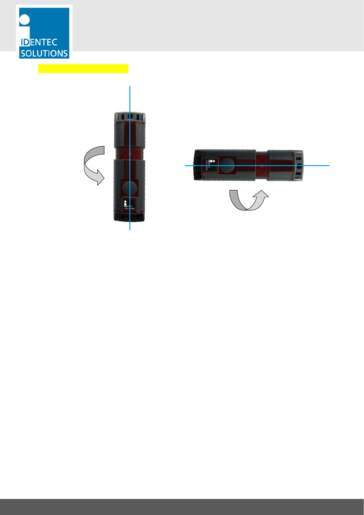
2.3.2. Polarization of Sensors
!
!
Vertically polarized
Horizontally polarized
Polarization is dependent on orientation and is rotation symmetrical.
i-Q350LX GPS -SAT
USER MANUAL
VISIBILITY DELIVERED. PAGE 14 OF 31
2.4. System Components—Readers
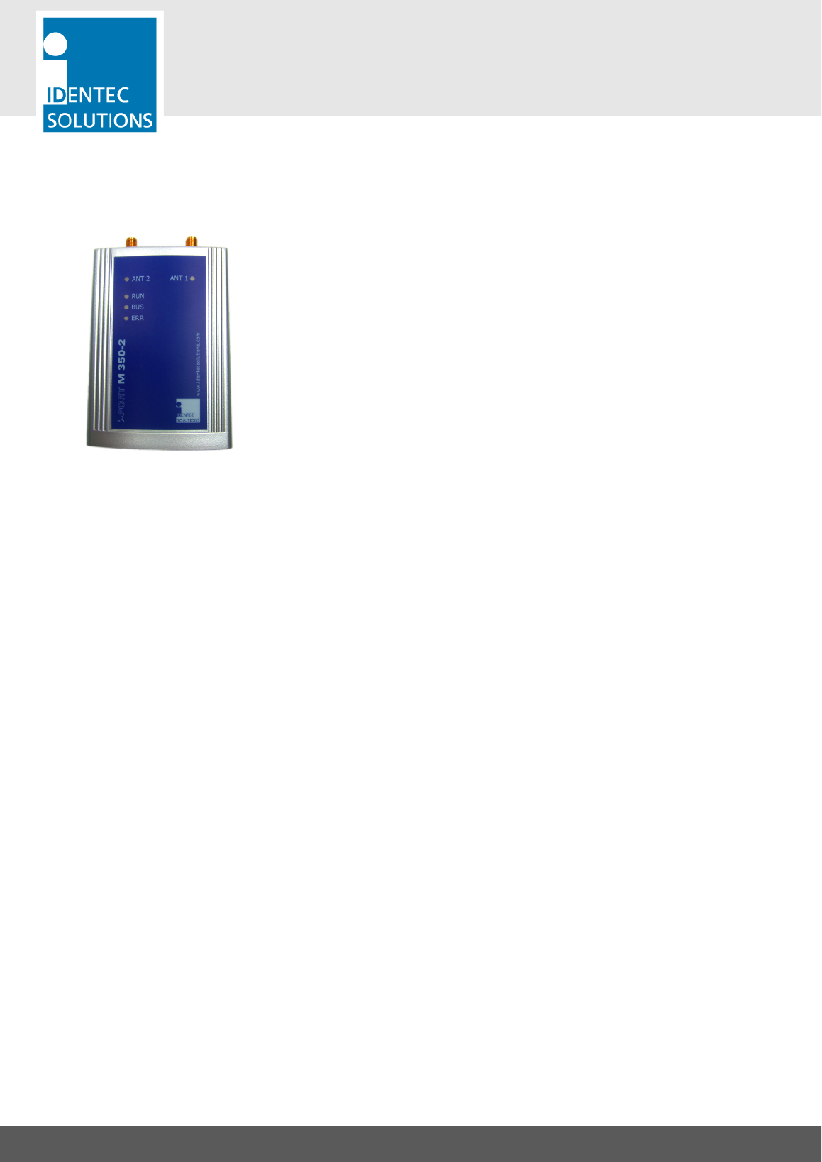
2.4.1. i-PORT M350-2
The i-PORT M350-2 is a reader for the i-Q350 and i-B350 series of
IDENTEC SOLUTIONS’s Response and Broadcast Sensors. Built into a
compact housing, the i-PORT M350-2 reads and writes data to the sensors
at distances of up to 500 meters (1640 feet) on two antennas. Connection
to the host system is established via a RS422 interface, resulting in the
capability to connect up to 8 readers in a Daisy Chain using commercially
available CAT 5 cables and connectors.
A simple master/slave protocol enables data exchange. Not only does the
protocol contain the data received from the sensor but it can also provide
information about the time of data reception, field strength and information
about the number of times the sensor has been received by the reader.
i-Q350LX GPS -SAT
USER MANUAL
VISIBILITY DELIVERED. PAGE 15 OF 31
2.5. System Components—Antennas
IDENTEC SOLUTIONS’ antennas are distinguished by their compact design. A variety of antennas can be used,
depending on application. The antennas are differentiated by characteristics such as polarization, apex angle,
and gain. Optimal fit to the reading zone is achieved by the right choice of antenna (characteristics) and
receive sensitivity. As the antennas are passive system elements, no tuning is required, which facilitates
installation and maintenance.
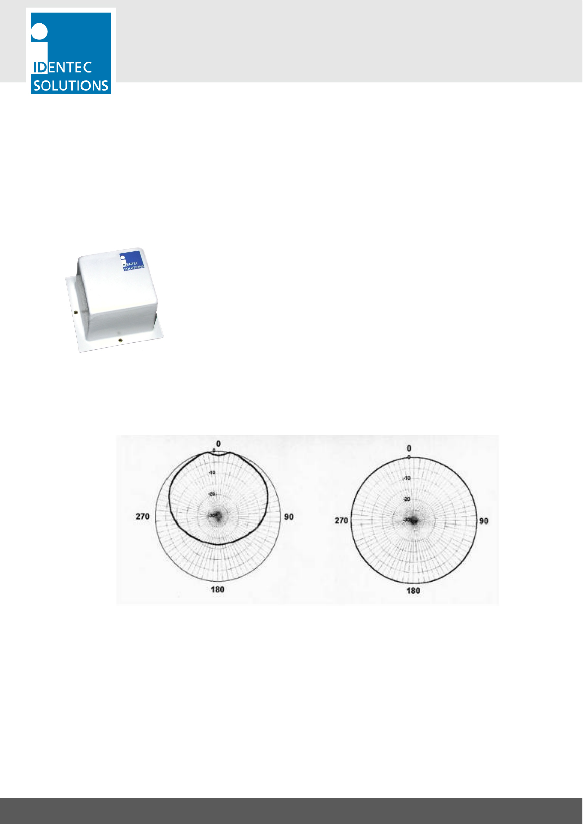
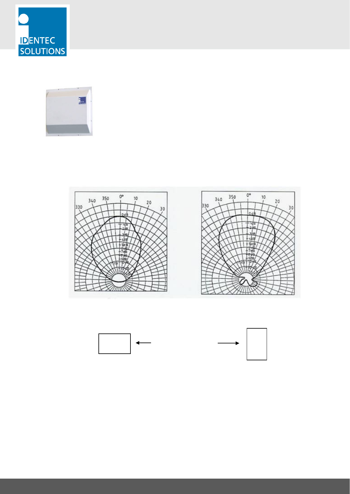
2.5.1. Elliptical Polarized Antennas
Because of the wide apex angle (120º), a large read zone is achieved,
which is desirable when a large quantity of sensors need to be read at one
time, or when sensors moving at great speeds need to be interrogated.
Since the polarization is elliptical, orientation of the sensor relative to the
antenna is not important; if the sensor is in front of the antenna the sensor
may be polarized horizontally or vertically along the line of sight of the
antenna. Due to its small size and weight, this antenna is very easy to
integrate.
Orientation Diagrams: Elliptical polarized antenna
Elevation Azimuth
For this antenna, the maximum transmit power setting is:
• A-9185: -8 dBm
i-Q350LX GPS -SAT
USER MANUAL
VISIBILITY DELIVERED. PAGE 16 OF 31
2.5.2. Linear Polarized Antennas
Because of the smaller apex angle (60º), this antenna is more suited to
selective data collection and restriction of read zones.
Depending on the direction of mounting, the antenna’s field is either
vertically or horizontally polarized, requiring the sensor to have the same
orientation.
Because of the greater gain, longer read ranges can be achieved with this
antenna compared to the elliptical polarized type above.
Orientation Diagrams: Linear polarized antenna
Elevation Azimuth
Vertical Polarization Horizontal Polarization
For this antenna, the maximum transmit power setting is:
• W-900R: -12 dBm
Antenna Orientation
i-Q350LX GPS -SAT
USER MANUAL
VISIBILITY DELIVERED. PAGE 17 OF 31
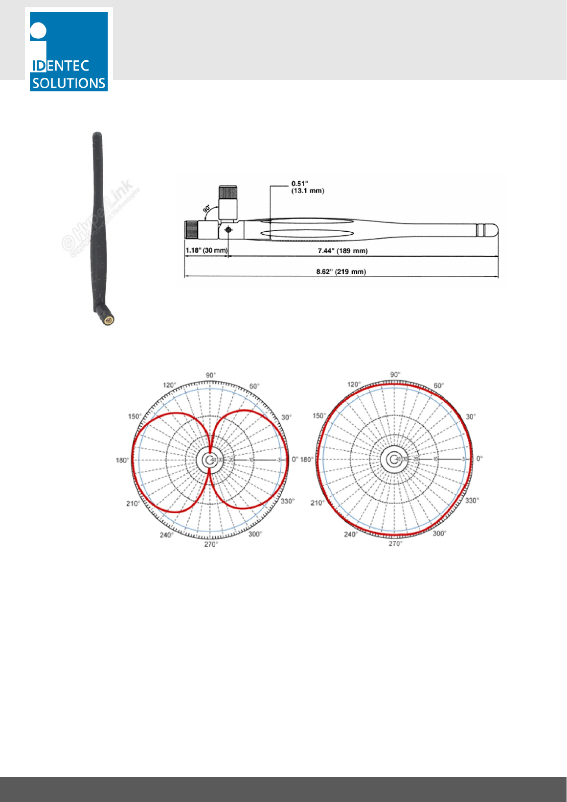
2.5.3. 1/2-Wave Whip Antenna
Dimensions
Orientation Diagrams
Elevation Azimuth
Vertical Polarization Horizontal Polarization
For this antenna, the maximum transmit power setting is:
• Rod antenna: -3 dBm
i-Q350LX GPS -SAT
USER MANUAL
VISIBILITY DELIVERED. PAGE 18 OF 31
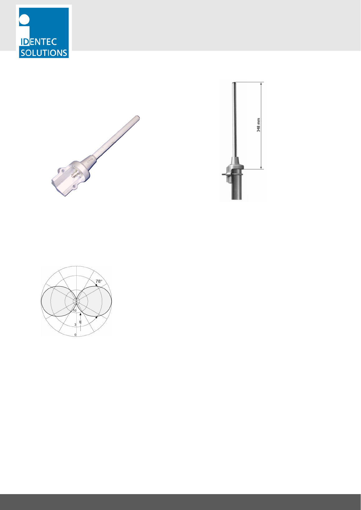
2.5.4. 1-Wave Rod Antenna
Overall Dimensions: 425 × 90 mm Mounting proposal
Antenna diagram
vertical
For this antenna, the maximum transmit power setting is:
• Rod antenna: -3 dBm
i-Q350LX GPS -SAT
USER MANUAL
VISIBILITY DELIVERED. PAGE 19 OF 31
1 Tag Mounting Techniques
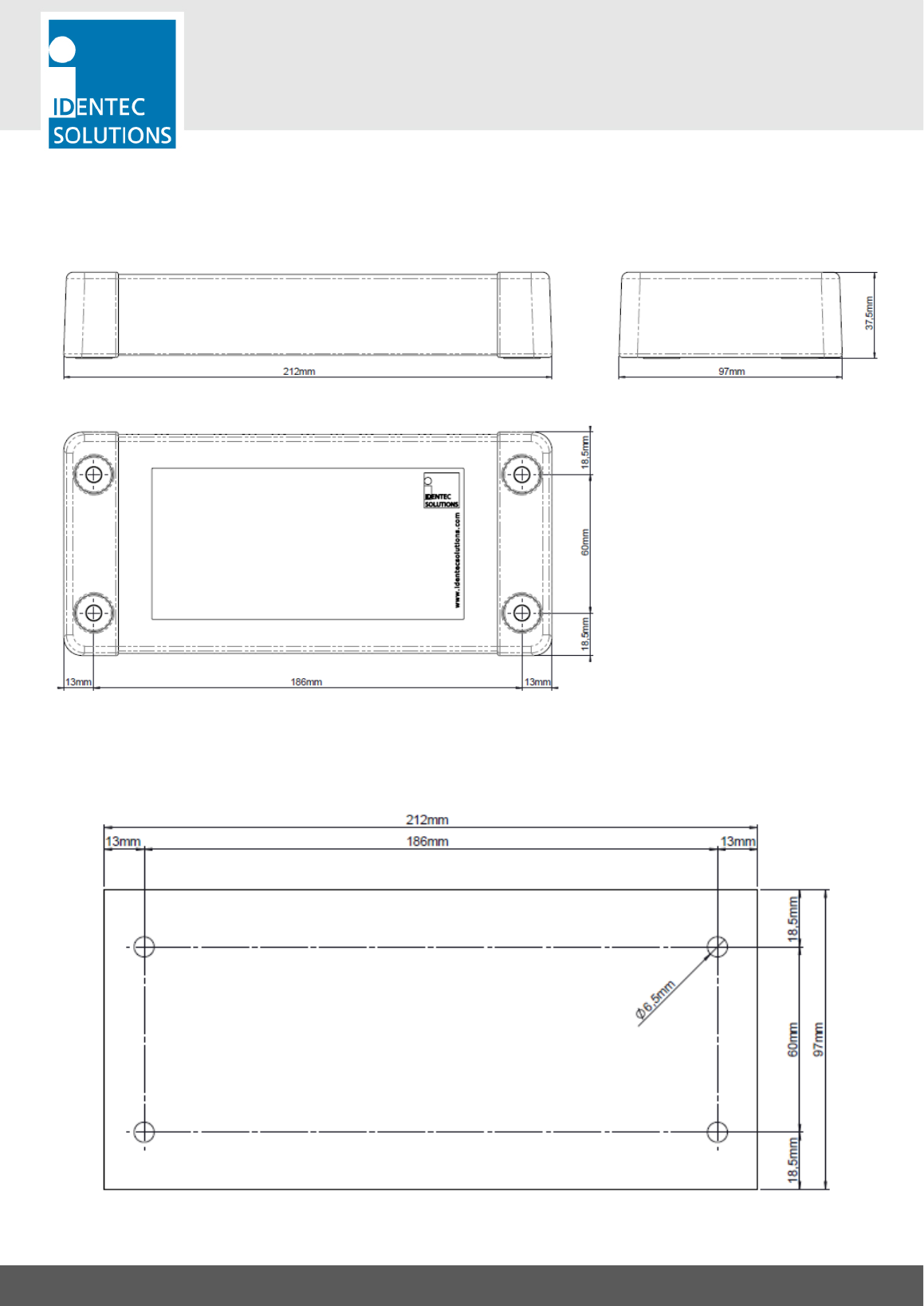
1.1 Dimensional Drawing
All dimensions in mm.
1.2 Mounting hole pattern

i-Q350LX GPS -SAT
USER MANUAL
VISIBILITY DELIVERED. PAGE 20 OF 31
1.3 Mounting to container
Mounting on container side wall
Make sure that the tag is mounted with a minimum
distance of 50mm from the frame. Shielding of the
tag can lead to a performance loss. Best performance
can be achiebved with a clear line of sight to the sky.
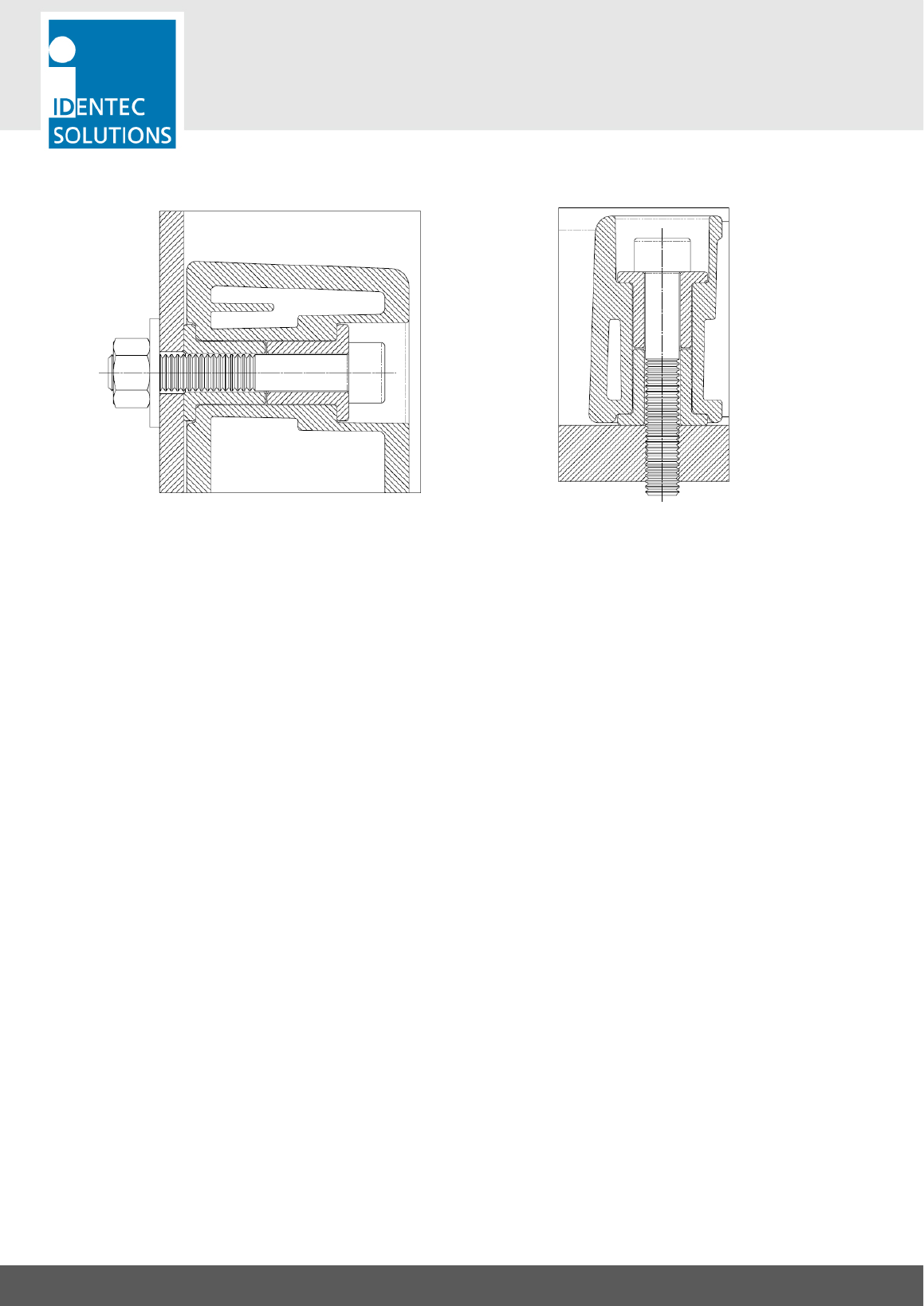
i-Q350LX GPS -SAT
USER MANUAL
VISIBILITY DELIVERED. PAGE 21 OF 31
1.4 Screws
Important Information
1. Tag shall only be mounted on flat and smooth surface. Warped and uneven surface can lead to
damages and to water ingress.
2. Mounting holes must not exceed a diameter of 6.5mm.
3. Only screws with cylindrical Allen heads are suitable for mounting the tag. We do not recommend
using countersunk screws or screws with hexagon heads.
4. Secure the screws with self-locking nuts, spring washers or Nord-lock washers. Self-cutting tapping
screws can become loose over time and should be checked regularly.
5. If the tag is mounted outdoors or in a damp environment, all mounting parts need to be made of
stainless steel or other non-rusting material.
6. A temperature of at least +10 °C (+50 °F) must be maintained during mounting to prevent the casing
from cracking.
7. Recommended maximum torque (for screws with property class 8.8)
M6/#14: 6.0 Nm
8. If the torque is any greater, the screw may over-tighten or the housing can be damaged.
9. Metal surfaces in direct proximity to the tag may reduce the tag’s range of function. Tags should not
be mounted in metal recesses or corners.
10. After mounting, the tag’s function should be tested with appropriate devices and software.

i-Q350LX GPS -SAT
USER MANUAL
VISIBILITY DELIVERED. PAGE 22 OF 31
2.6. Tag Identification
Model description
Type description
ATEX reference
Manufacturer information
i-Q350LX GPS -SAT
USER MANUAL
VISIBILITY DELIVERED. PAGE 23 OF 31
3. INITIAL OPERATION, CONFIGURATION OF THE TAG
3.1. General
Important Note
Do not open the housing! Configuration is done using the built-in air interface of the i-Q350TLX FL.
The Response mode of the i-Q350L GPS -SAT offers the following features for configuration:
• Broadcast mode can be configured for simultaneous operation. In this case the tag responds to
commands from a reader as well as broadcasts configurable data in a regular interval.
Tools Needed
• PC running on MS Windows with the Tag Configuration for SSP 350 series tags
• Connection to an i-PORT M 350 or i-CARD CF 350 to communicate with the tags
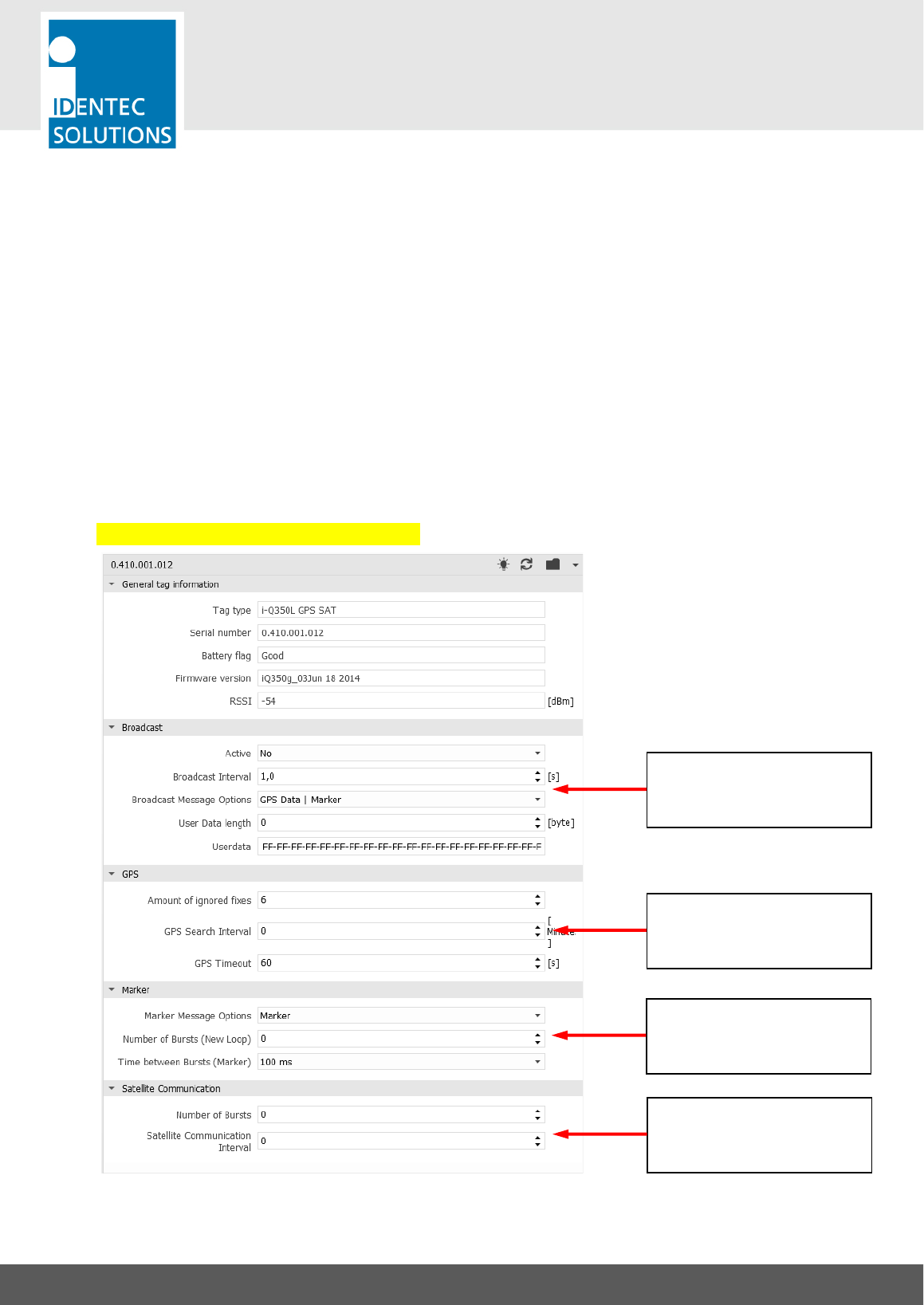
Overview on the Configuration Software
Select Ping Rate and Ping
Message Content in the block
“Broadcast”
Select Number of bursts
(new loop) in the block
“Marker”
GPS Settings
Satellite Settings
i-Q350LX GPS -SAT
USER MANUAL
VISIBILITY DELIVERED. PAGE 24 OF 31
3.2. Ping Rate
Note: These settings can be found in the Tag Configuration software tool in the section “Broadcast”
• Active: Activates or de-activates the broadcast function that regularly sends out messages.
• Broadcast Interval: 0 = no broadcast messages are sent, value > 0 = Broadcast interval in seconds. This
can be set in steps of 0.5 sec, from 0.5 sec up to 300 sec.
• Broadcast Message Options: The options in this field depend on the capabilities of the tag. The
subchapter “Limitations of the User Data Field” lists the possible options of this tag type.
• User Data Length: Configure the number of Bytes from the “User Data” that is sent with a broadcast
message. The number starts from Byte 0 (zero). The limits of the User Data length are described at the
end of this chapter
3.1. Limitations of the User Data Field
The total length of the broadcast message (burst or ping) is limited to 50 Bytes. Depending on the broadcast
message options, these are the allowed number of bytes for the user data:
Message Type
Length of User Data
User Data only
max. 50 Bytes
GPS | User Data
max. 42 Bytes
Marker | User Data
max. 38 Bytes
Marker | User Data | GPS
max. 31 Bytes
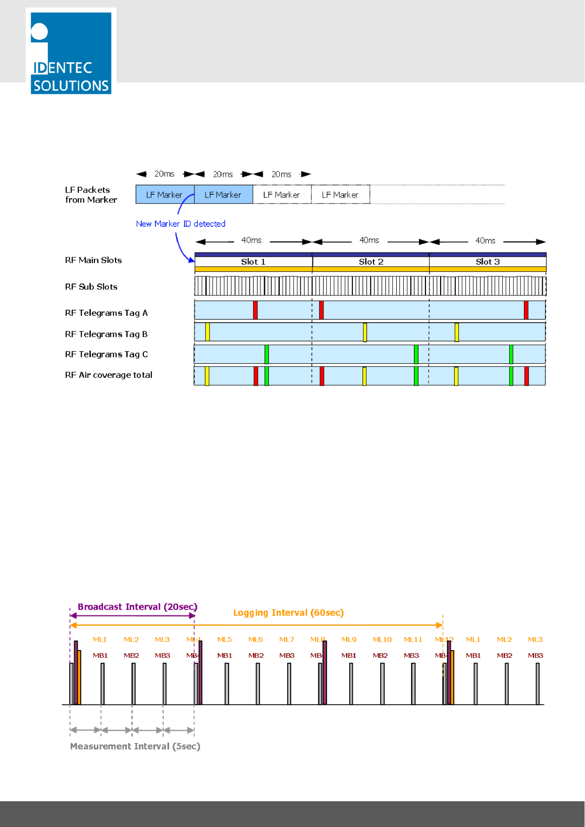
3.2. Information on Burst Settings
The parameter “Time between Bursts (Marker)” is not simply a delay time. It is in fact a timeslot. In this
timeslot the tag chooses a random moment to do a single burst. This avoids that burst collisions with other
tags, that are simultaneously triggered by the same marker loop. These timeslots are repeated until all bursts
are sent.
In the event that dozens of tags are triggered to burst at once, this value can be increased. The result of
increasing the slot width is there will be a longer time interval between other bursts being sent. Fore example
with an increased value of 700 ms and 8 bursts, the amount of time for all bursts is 5.6 seconds.
i-Q350LX GPS -SAT
USER MANUAL
VISIBILITY DELIVERED. PAGE 25 OF 31
Example
This example shows 3 tags (A, B, C) that are simultaneously triggered by a marker loop (LF marker) and are
configured to burst 3 times. The timeslot (Time between Bursts) is set to the default value of 40 ms.
The last row shows how the random use of the timeslot avoids collision between the tags.
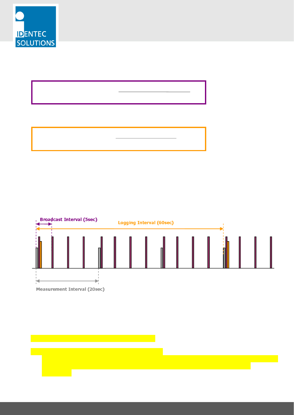
3.3. Impact between measurement, logging and broadcast interval
The intervals for temperature measurement, temperature logging and broadcasts can be configured
independently.
Example 1
Measurement Interval: 5 sec
Broadcast Interval: 20 sec
Logging Interval: 60 sec
i-Q350LX GPS -SAT
USER MANUAL
VISIBILITY DELIVERED. PAGE 26 OF 31
If the measurement interval is shorter than the broadcast interval, the tag broadcasts the average value
measured during the time between broadcasts. In this example the value is an average over the 4 measured
values during the broadcasts:
With a longer logging interval, the average temperature for logging is calculated as follows:
Example 2
Measurement Interval: 20 sec
Broadcast Interval: 5 sec
Logging Interval: 60 sec
If the broadcast interval is shorter than the measurement interval the tag broadcasts the last measured value
untill the tag measures a new one. In this example the tag sends the same value 4 times. The logged value is
still the average during the log interval.
3.4. GPS and Satellite communication settings
3.5. Globalstar Satellite communication activation
The Globalstar Satellite module with the FCC ID can be accessed by carefully removing
the back panel of the device. The module is properly labeled with the FCC ID:
L2V-STX3
Avg. Temperature for Broadcast =
4
MB1 + MB2 + MB3 + MB4
ML1 + ML2 + … + ML12
Avg. Temperature for Logging =
12

i-Q350LX GPS -SAT
USER MANUAL
VISIBILITY DELIVERED. PAGE 27 OF 31

i-Q350LX GPS -SAT
USER MANUAL
VISIBILITY DELIVERED. PAGE 28 OF 31
4. MAINTENANCE
4.1. General
When installed correctly the SensorSMART System will operate virtually maintenance free for many years.
However, in the event maintenance is required only trained and authorized personnel are permitted to
perform the updates, changes and maintenance necessary.
4.2. Regular Cleaning of The Surface
Remove dust with a brush or compressed air. If there are fatty or oily substances use a soft cloth moistened
with a mild rinsing agent.
Warning
Do not clean the tag in a dishwasher. Do not sandblast the tag. Do not use high pressure water jet or steam
cleaner. Do not use cleaning products containing chemical additives.
WARNING - Electrostatic Hazard: Clean plastic Tag surface only with a damp cloth. Do
not use solvents.
4.3. Precautionary Maintenance
A regular check of the system is recommended. Unstable connections could lead to damage and malfunctions
of the system and should therefore be repaired as soon as possible.
A Brief Checklist
• Are all housings intact?
• Are all cables intact?
• Are all connectors intact?
• Are all connectors securely fastened?
• Are all screws still tight?
• Is there a malfunction at a specific unit?

i-Q350LX GPS -SAT
USER MANUAL
VISIBILITY DELIVERED. PAGE 29 OF 31
4.4. Returns
Parts or main components returned for repair or exchange must be handled with great care. PC cards must be
returned in the appropriate ESD-protecting packaging material. Please follow the RMA policy under:
http://cdn.identecsolutions.com/wp-content/uploads/2012/06/IMS_PD-OPS-
014_Hardware_Return_and_Repair_Policy_03e.pdf
Return to:
IDENTEC SOLUTIONS AG
Service Department
Millennium Park 2
6890 Lustenau
AUSTRIA

i-Q350LX GPS -SAT
USER MANUAL
VISIBILITY DELIVERED. PAGE 30 OF 31
5. TECHNICAL DATA
Communication Broadcast 350
Operation Mode
Transmits Tag ID and user data in pre-defined interval
Read Range
up to 500m (1600ft)*
Compatibility
i-PORT M350, i-CARD CF 350 and i-PORT 4-350
Operating Frequency
868 MHz (EU) or 920 MHz (NA)
Transmit Power
<1mW
Communication Response 350
Operation Mode
Bi-directional communication (reading log, blink LED, write/read data)
Read Range
up to 250m (800ft)*
Compatibility
i-PORT M350 and i-CARD CF 350
Operating Frequency
868 MHz (EU) or 920 MHz (NA)
Transmit Power
<1mW
Communication Marker
Operation Mode
Receives Marker ID and transmits marker information several times
via Broadcast 350 telegrams
Read Range
up to 5m (16ft)*
Compatibility
i-MARK
Operating Frequency
125 kHz
*!The!communication!range!depends!on!the!antenna!type,!the!antenna!cable!runs!
and!the!environmental!conditions.!
Communication GPS
Receiver type
50 Channels GPS L1 frequency, C/A Code
Time-To-First-Fix
Cold Start 26 s
Hot Start 1 s
Horiz. Position Accuracy
GPS 2.5 m
Communication Satellite
Frequency
1.610 – 1.620 GHz
Protocol
Simplex
Modulation
Direct Sequence Spread Spectrum (DSSS)
Average TX Power
18 dBm +/- 2 dB RMS
Maximum TX Time
1.4 seconds
Packet Size
9 bytes (or custom programmable)
Electronic Serial Number
Each unit identified with a unique ESN
Certification
Globalstar
Data
Data Retention
> 10 years without power
Write Cycles
1.000.000 writes
Memory Size
30.000 Bytes user defineable
Identification Code
48 bit fixed ID
Sensors
Shock
up to 100G on all 3 axis, 50mG sensitivity
Motion
up to 8G on all 3 axis, 4mG sensitivity
Configuration
Device
i-PORT M350 or i-CARD CF350
Ping Rate
Configurable from 0.5 to 300 seconds insteps of 0.5 seconds
Number of Bursts
Configurable from 0 to 15
Broadcast User Data
Up to 50 Bytes
GPS fixes
Configurable
Satellite communications
Configurable

i-Q350LX GPS -SAT
USER MANUAL
VISIBILITY DELIVERED. PAGE 31 OF 31
Electrical
Power Source
4x Lithium battery 2200mAh (not user-replaceable)
Battery lifetime expectancy
4 years @ 10 seconds ping rate, 2 GPS fixes and 2 satellite
communcations per day
Environmental Conditions
Operating Temperature
–30 °C to +60 °C (–22 °F to +140 °F)
Humidity
10% to 95% relative humidity @ 30°C
Shock
EN 60068-2-32: Multiple drops to concrete from 1m (3ft), 5 times
EN 60068-2-29: 50G on all 3 axis, 3 times per axis
Vibrations
EN 60068-2-6: 5G, 20 sin wave cycles per axis, 5-500Hz
EN 60068-2-64: noise 5 to 1000Hz, 90 minutes per axis
Standard/Certification
Europe**
CE (EN 300 220-1, -3; EN 301 489-1,-3; EN 60950)
North America**
FCC Part 15 (US); Industry Canada
ATEX/IECEx**
ATEX Zone 0 (II 1 G Ex ia IIC T4)
**Certification!pending!
Mechanical Data
Dimensions
210 x 95 x 37 mm (8.3 x 3.7 x 1.5 inches)
Enclosure Material
PA 6.6 GF30 and rubber end caps
Enclosure Rating
IP67 (immersion up to 1m) & IP69K (high pressure water jets)
Weight
500 grams (18 ounces)