InBody BSM170B Stadiometer User Manual Part 1
InBody Co., Ltd. Stadiometer Part 1
UserManual.wiki
>
InBody
>
BSM170B User Manual
>
User Manual Part 1
Contents
1.
User Manual Part 1
2.
User Manual Part 2
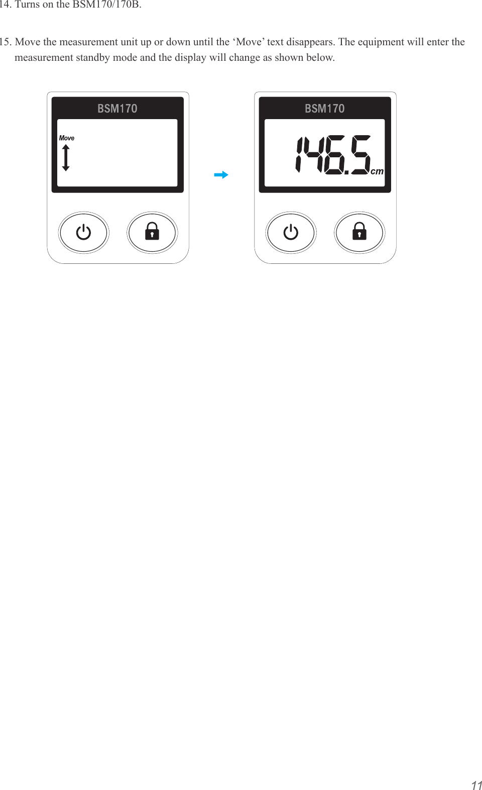
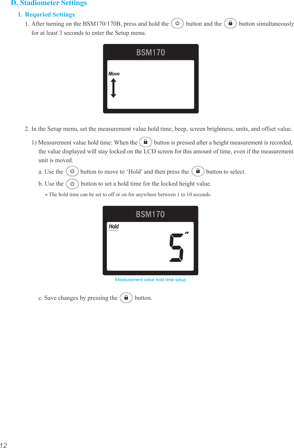
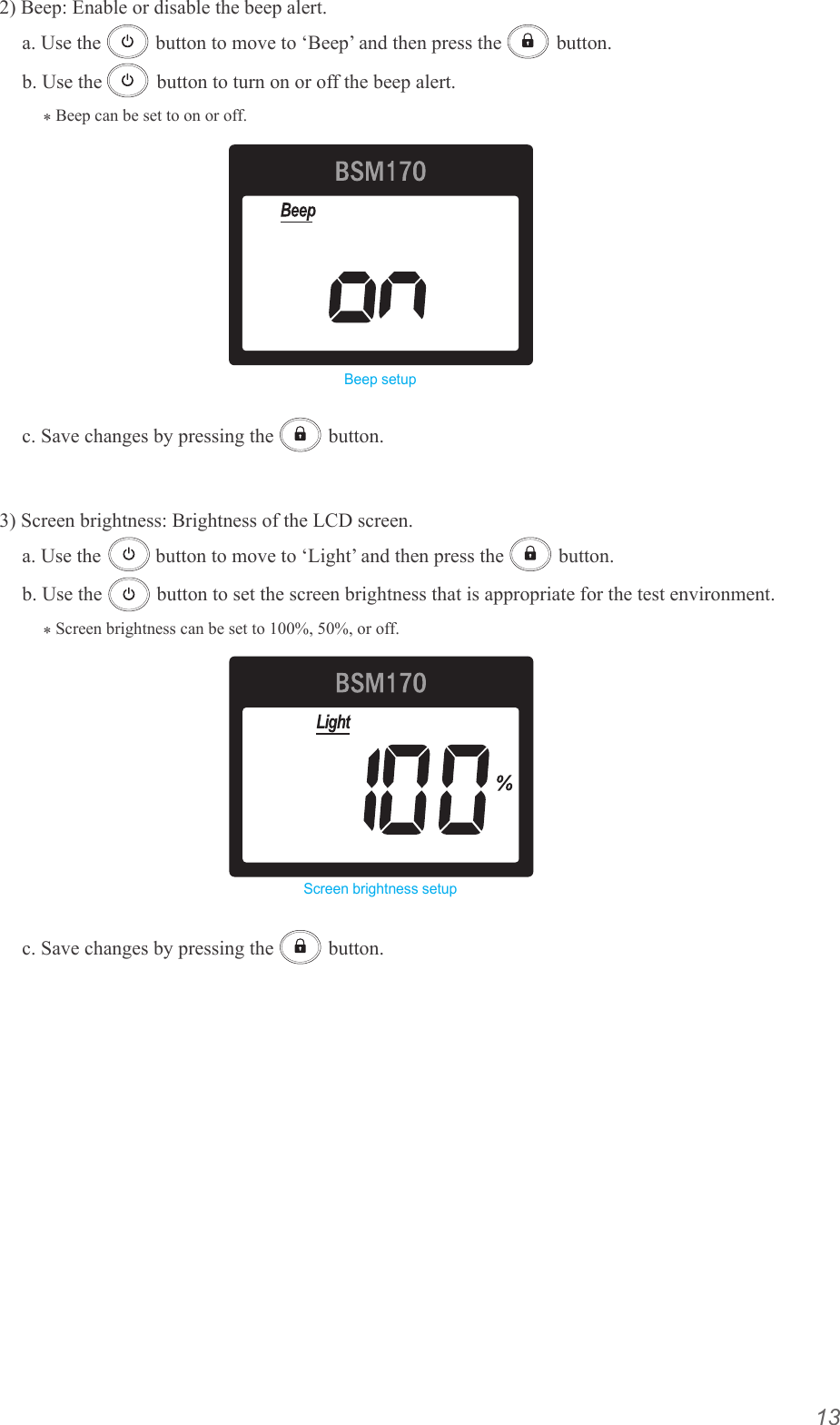
User Manual Part 1
Navigation menu
Upload a User Manual
Namespaces
Wiki Guide
HTML
PDF
Info
Views
User Manual
Discussion / Help
Navigation
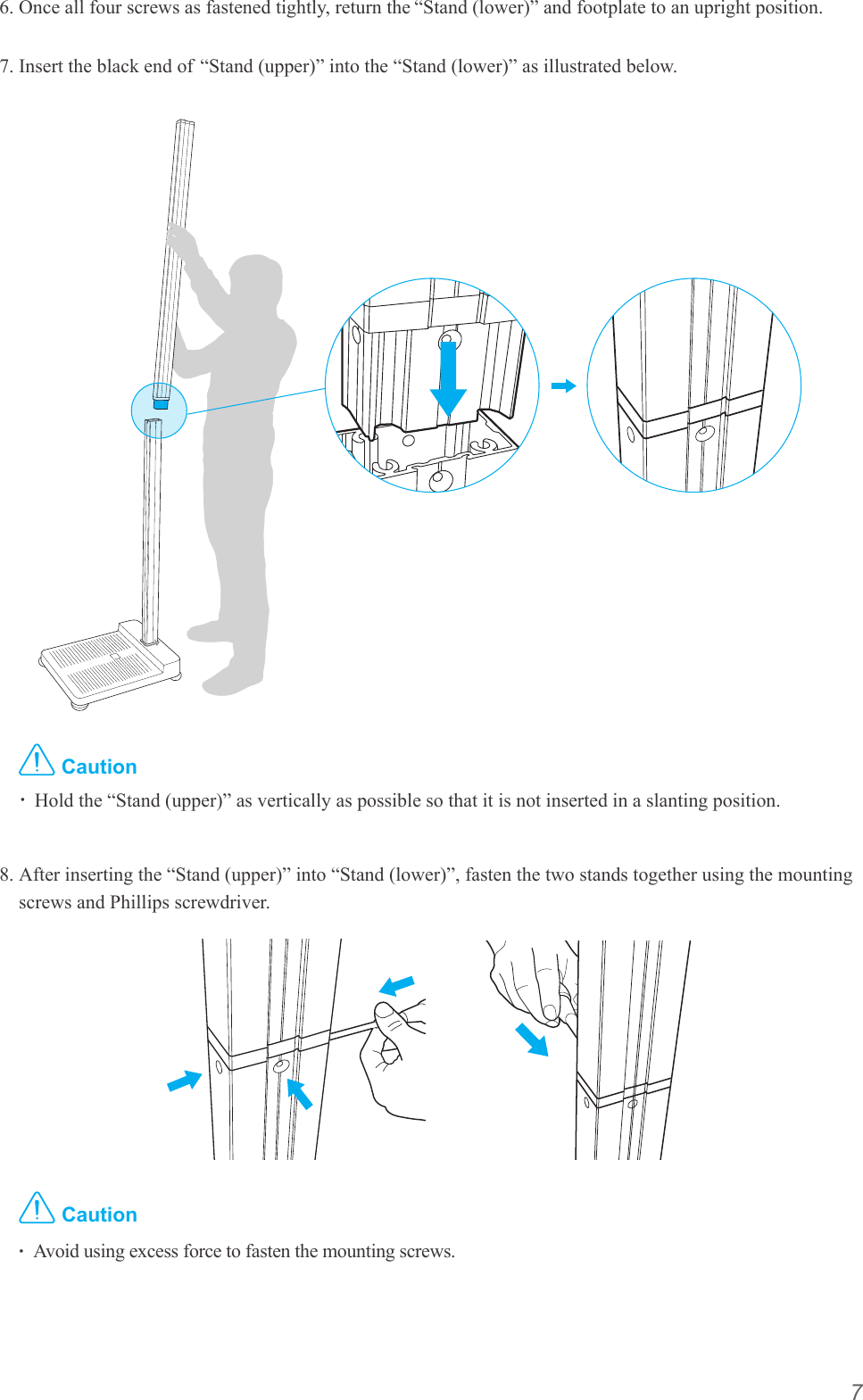
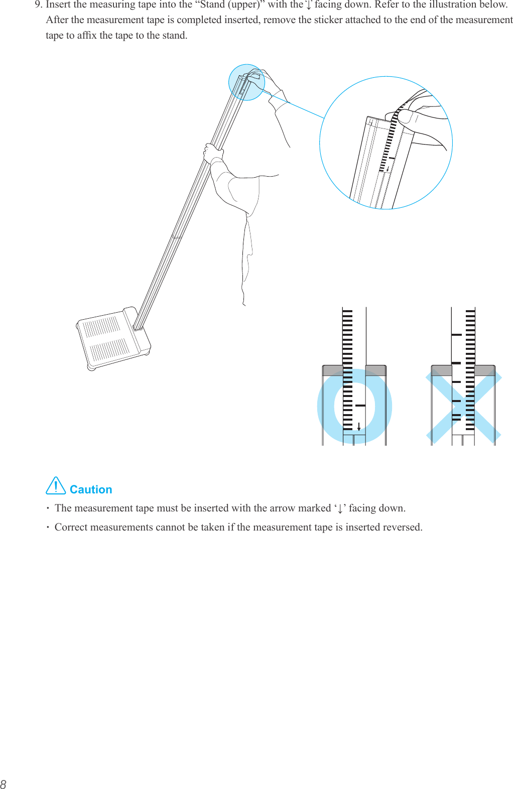
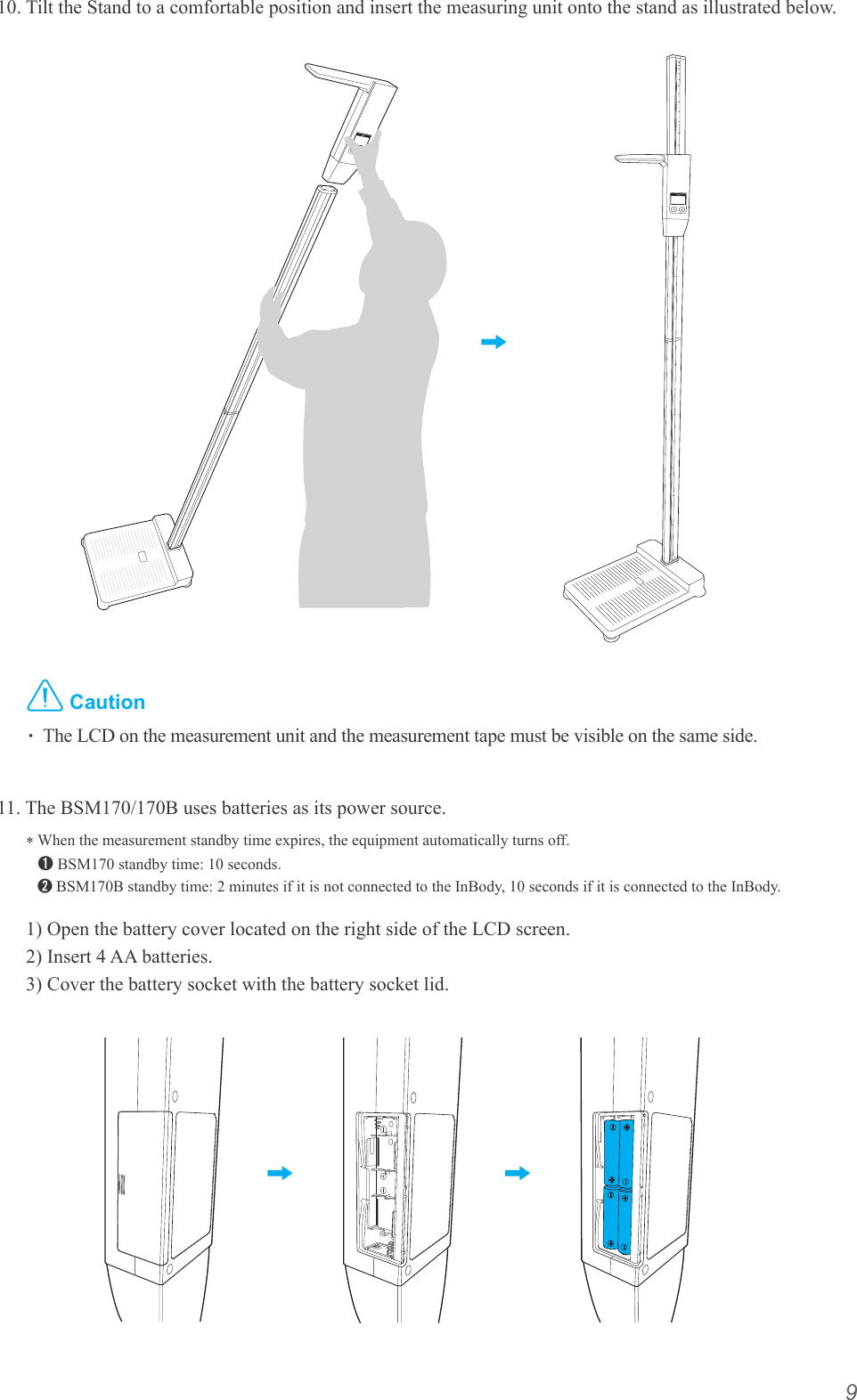
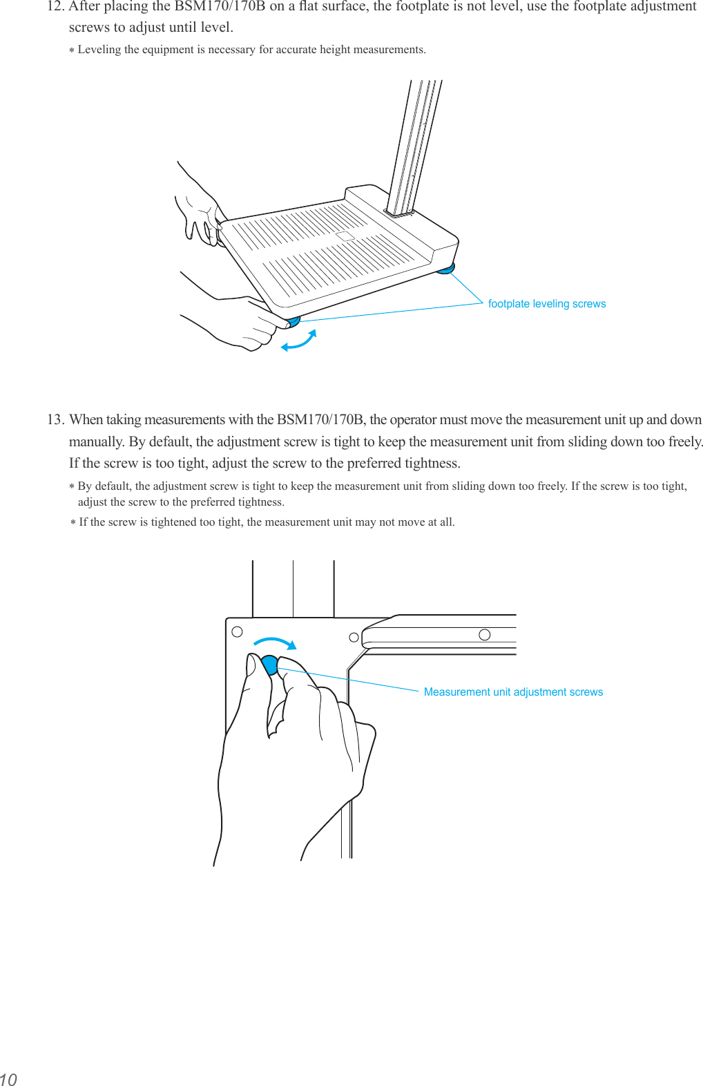
![ⓒ2014 InBody Co., Ltd. All rights reserved. BM-ENG-E9-B-140827For any problems with BSM170/170B or any clinical questions, please contact us at the following:InBody Co., Ltd. [HEAD OFFICE]InBody Bldg., 54, Nonhyeon-ro 2-gil, Gangnam-gu, Seoul, KoreaTEL: +82-2-501-3939 FAX: +82-2-578-2716 Website: http://www.inbody.comE-mail: info@inbody.comReproduction, adaptation, or translation of this manual is prohibited without prior written consent from InBody Co., Ltd under the copyright laws. This manual might have typographical errors, and its content can be changed without a prior notice. InBody Co., Ltd. shall not be liable for any errors, incidental, or consequential damages that occurred by not complying with the content of the User's Manual.Visit our website http://www.inbody.com to view and download further information about the functions of the BSM170/170B, the explanation of results output, and more. InBody Co., Ltd reserves the right to modify the appearance, specifications, and etc. of the BSM170/170B to improve the quality of the product, without prior notice for reasons of performance improvement.Please note the important information below before reading this manual.Failure to comply with safety warnings and regulations can cause serious injury or death.DANGERNOTECAUTION참 조 주 의참 고 주 의Failure to comply with safety cautions and regulations can cause injury or property damage.DANGERNOTECAUTION참 조 주 의참 고 주 의WarningCautionCustomer Service InformationInBody USA [USA]13850 Cerritos Corporate Dr., Unit C, Cerritos, CA 90703, USATEL: +1-323-932-6503 FAX: +1-323-952-5009 Website: http://www.inbodyusa.com E-mail: USA@biospaceamerica.comInBody Japan Inc. [JAPAN]Second Floor Ayabe Bldg., 2-17-3 Sotokanda, Chiyoda-ku, Tokyo JAPANTEL: +81-03-5298-7667 FAX: +81-03-5298-7668 Website: http://www.inbody.co.jp E-mail: inbody@inbody.co.jpEU Representative. [EUROPE]DongBang Acuprime. 1 Forrest Units, Hennock Road East, Marsh Barton, Exeter EX2 8RU, U.KTEL: +44-1392-829500 FAX: +44-1392-823232 Website: http://www.inbody.com E-mail: info@acuprime.comBiospace China. [CHINA]904, Xing Di Plaza, No. 1698 Yishan Road, Shanghai, 201103, CHINATEL: +86-21-64439738, 9739, 9705 FAX: +86-21-64439706 Website: http://www.biospacechina.com E-mail: info@biospacechina.comAustralian Sponsor. [AUSTRALIA]Emergo AUSTRALIA. Level 20, Tower Ⅱ, Darling Park, 201 Sussex Street, Sydney, NSW 2000, AUSTRALIATEL: +61-2-9006-1662 FAX: +61-2-9006-1010 Website: http://www.emergogroup.com E-mail: Sponsor@emergogroup.com](https://usermanual.wiki/InBody/BSM170B.User-Manual-Part-1/User-Guide-2402028-Page-2.png)