Contents
- 1. User Manual Part 1
- 2. User Manual Part 2
User Manual Part 1
User's Manual

ⓒ
2014 InBody Co., Ltd. All rights reserved. BM-ENG-E9-B-140827
For any problems with BSM170/170B or any clinical questions, please contact us at the following:
InBody Co., Ltd. [HEAD OFFICE]
InBody Bldg., 54, Nonhyeon-ro 2-gil, Gangnam-gu, Seoul, Korea
TEL: +82-2-501-3939 FAX: +82-2-578-2716
Website: http://www.inbody.com
E-mail: info@inbody.com
Reproduction, adaptation, or translation of this manual is prohibited without prior written consent from InBody Co., Ltd
under the copyright laws. This manual might have typographical errors, and its content can be changed without a prior
notice. InBody Co., Ltd. shall not be liable for any errors, incidental, or consequential damages that occurred by not
complying with the content of the User's Manual.
Visit our website http://www.inbody.com to view and download further information about the functions of
the BSM170/170B, the explanation of results output, and more. InBody Co., Ltd reserves the right to modify
the appearance, specifications, and etc. of the BSM170/170B to improve the quality of the product, without
prior notice for reasons of performance improvement.
Please note the important information below before reading this manual.
Failure to comply with safety warnings and regulations can cause serious injury or death.
DANGER
NOTECAUTION
참 조 주 의참 고 주 의
Failure to comply with safety cautions and regulations can cause injury or property damage.
DANGER
NOTECAUTION
참 조 주 의참 고 주 의
Warning
Caution
Customer Service Information
InBody USA [USA]
13850 Cerritos Corporate Dr., Unit C, Cerritos, CA 90703, USA
TEL: +1-323-932-6503 FAX: +1-323-952-5009 Website: http://www.inbodyusa.com E-mail: USA@biospaceamerica.com
InBody Japan Inc. [JAPAN]
Second Floor Ayabe Bldg., 2-17-3 Sotokanda, Chiyoda-ku, Tokyo JAPAN
TEL: +81-03-5298-7667 FAX: +81-03-5298-7668 Website: http://www.inbody.co.jp E-mail: inbody@inbody.co.jp
EU Representative. [EUROPE]
DongBang Acuprime. 1 Forrest Units, Hennock Road East, Marsh Barton, Exeter EX2 8RU, U.K
TEL: +44-1392-829500 FAX: +44-1392-823232 Website: http://www.inbody.com E-mail: info@acuprime.com
Biospace China. [CHINA]
904, Xing Di Plaza, No. 1698 Yishan Road, Shanghai, 201103, CHINA
TEL: +86-21-64439738, 9739, 9705 FAX: +86-21-64439706 Website: http://www.biospacechina.com E-mail: info@biospacechina.com
Australian Sponsor. [AUSTRALIA]
Emergo AUSTRALIA. Level 20, Tower Ⅱ, Darling Park, 201 Sussex Street, Sydney, NSW 2000, AUSTRALIA
TEL: +61-2-9006-1662 FAX: +61-2-9006-1010 Website: http://www.emergogroup.com E-mail: Sponsor@emergogroup.com

I. Stadiometer Installation
A. Product Components
B. Operating Environment
C. Installation Instructions
D. Stadiometer Settings
E. Maintenance
II. Height Measurement
A. Precautionary Measurements
B. Measurement Instructions
C. Measurement Posture
III.
Transportation and Storage
A. Repacking Instructions
B. Transportation and Storage Environment
IV.
Frequently Asked Questions
V. Others
A. Exterior and Functions
B. Symbols
C. Specications
4
5
5
12
18
19
20
21
22
22
23
24
26
27
User’s Manual Contents
4
I. Stadiometer Installation
A. Product Components
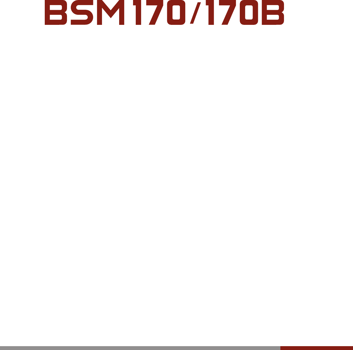
The BSM170/170B contains of the following components.
Make sure all of the following components are present.
* Please inspect each component of the BSM170/170B for damage prior to installation.
❶
Footplate 1 EA
❷
Stand (upper) 1 EA
❸
Stand (lower) 1 EA
❹
Measurement unit 1 EA
❺
Measurement tape 1 EA
❻
Footplate mounting screws 4 EA
❼
Stand mounting screws 8 EA
❽
User’s manual 1 EA
❾
AA batteries 4 EA
❿
Test Jig 1 EA
사용자매뉴얼
❹
사용자매뉴얼
➒
➓
사용자매뉴얼
❺❻❼
사용자매뉴얼
❷
❸
❶
➑
5
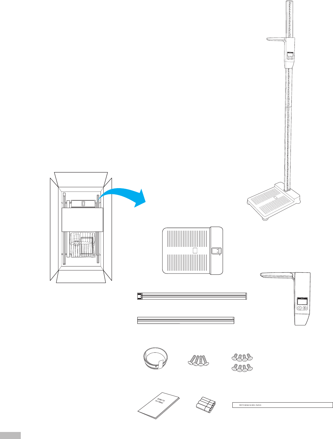
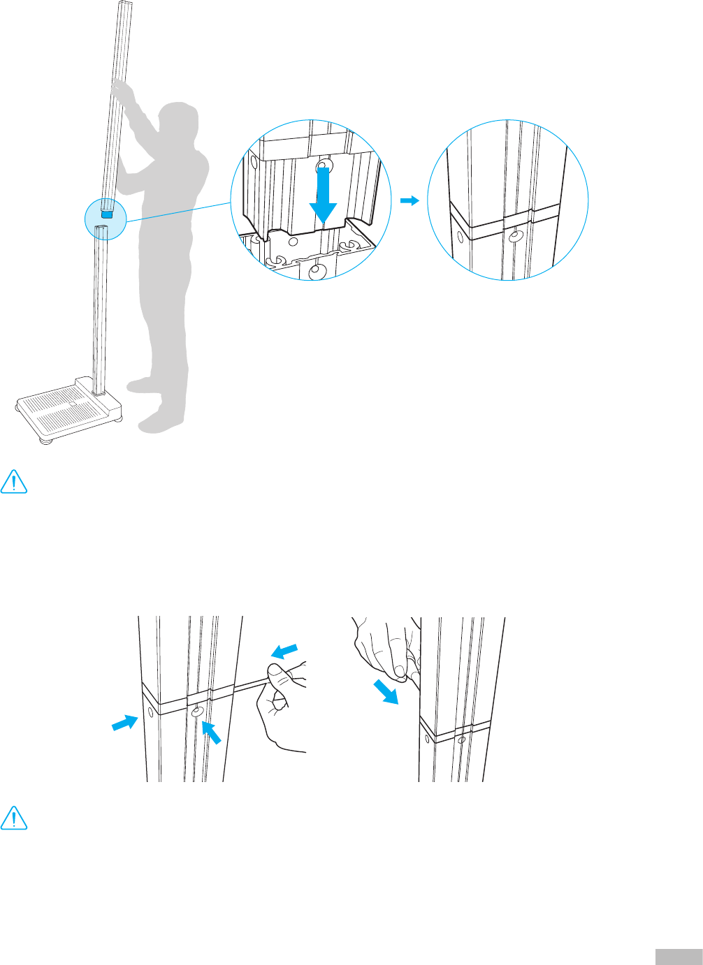
2. Insert the “Stand (lower)” into the footplate, ensuring that the arrow (▼) located on the bottom right of
the “Stand (lower)” and the arrow (▲) located on the footplate face one another.
* When inserting into the “Stand (lower)”, part without screw holes must face downward.
* The “Stand (lower)” and the footplate are designed to be assembled together in only one particular direction. Forcing the stand to
be inserted in other directions could damage the product.
B. Operating Environment
Please make sure that the environment is adequate for the BSM170/170B installation. This equipment is designed
for indoor use. If installing outdoors, the following requirements must be fullled.
Temperatures range 10 ~ 40℃ (50 ~ 104℉)
Relative humidity 30 ~ 75% RH
Atmospheric pressure 70 ~ 106kPa
•
Before installing BSM170/170B, check that the ceiling is at least 2.3 m high. The maximum height of this
equipment is 2.19m. Keep a space of at least 3cm between the ceiling and the top of the BSM170/170B.
DANGER
NOTECAUTION
참 조 주 의참 고 주 의
Warning
C. Installation Instructions
1. After opening the BSM170/170B box, remove the packaging materials and take all product components out.
•
Keep the packaging materials provided for repacking the equipment in the future. Other wastes should be
disposed of according to relevant laws and regulations.
•
Install the BSM170/170B on a leveled, non-vibrating surface. Installing the equipment on an uneven surface may
cause the examinee to fall down. Measurement results may also be inaccurate.
•
Never clean the BSM170/170B with liquid spray or detergent directly. The equipment may corrode and/or
malfunction if the liquid or detergent leaks inside. Additionally, BSM170/170B measurement tape may be damaged.
When cleaning the BSM170/170B, gently wipe it with the cloth.
DANGER
NOTECAUTION
참 조 주 의참 고 주 의
Warning
6
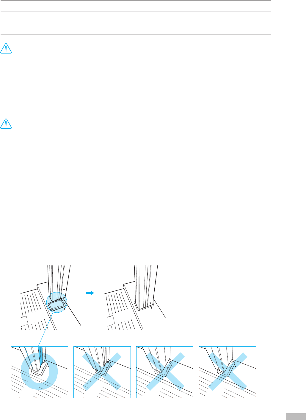
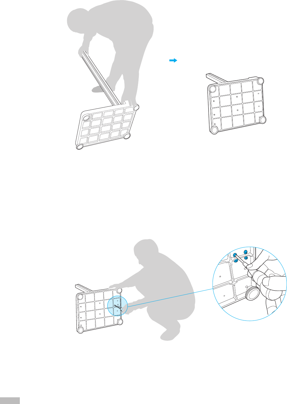
3. Hold the “Stand (lower)” in place to prevent it from sliding out of the insertion hole of the footplate,
tilt the equipment sideways towards the oor.
4. Screw each of the 4 footplate leveling screws into the holes located on the opposite side of the stand
insertion hole of the footplate.
5. Tighten the Stand mounting screws by turning them clockwise with the Phillips screwdriver.
7
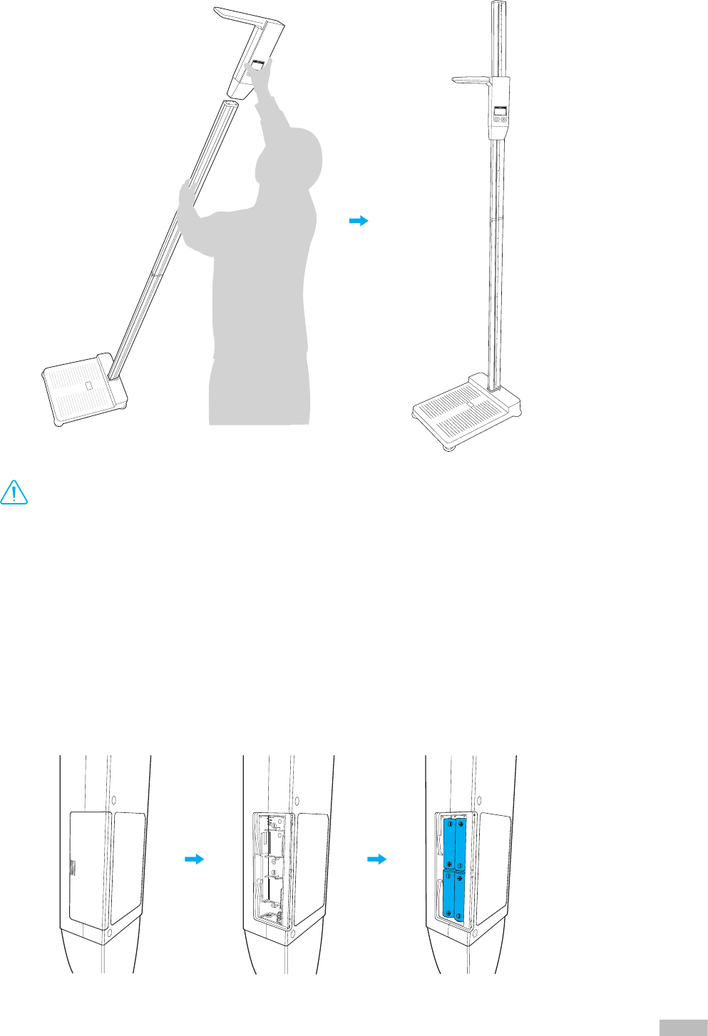
6. Once all four screws as fastened tightly, return the “Stand (lower)” and footplate to an upright position.
7. Insert the black end of “Stand (upper)” into the “Stand (lower)” as illustrated below.
•
Hold the “Stand (upper)” as vertically as possible so that it is not inserted in a slanting position.
DANGER
NOTECAUTION
참 조 주 의참 고 주 의
Caution
8. After inserting the “Stand (upper)” into “Stand (lower)”, fasten the two stands together using the mounting
screws and Phillips screwdriver.
•
Avoid using excess force to fasten the mounting screws.
DANGER
NOTECAUTION
참 조 주 의참 고 주 의
Caution
8
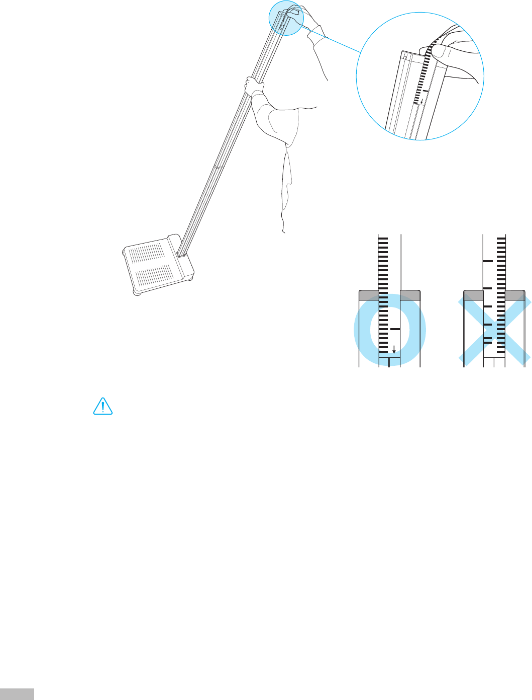
9. Insert the measuring tape into the “Stand (upper)” with the ̒↓̓ facing down. Refer to the illustration below.
After the measurement tape is completed inserted, remove the sticker attached to the end of the measurement
tape to afx the tape to the stand.
•
The measurement tape must be inserted with the arrow marked ‘↓’ facing down.
•
Correct measurements cannot be taken if the measurement tape is inserted reversed.
DANGER
NOTECAUTION
참 조 주 의참 고 주 의
Caution
9
11. The BSM170/170B uses batteries as its power source.
* When the measurement standby time expires, the equipment automatically turns off.
➊ BSM170 standby time: 10 seconds.
➋ BSM170B standby time: 2 minutes if it is not connected to the InBody, 10 seconds if it is connected to the InBody.
1) Open the battery cover located on the right side of the LCD screen.
2) Insert 4 AA batteries.
3) Cover the battery socket with the battery socket lid.
10. Tilt the Stand to a comfortable position and insert the measuring unit onto the stand as illustrated below.
•
The LCD on the measurement unit and the measurement tape must be visible on the same side.
DANGER
NOTECAUTION
참 조 주 의참 고 주 의
Caution
10
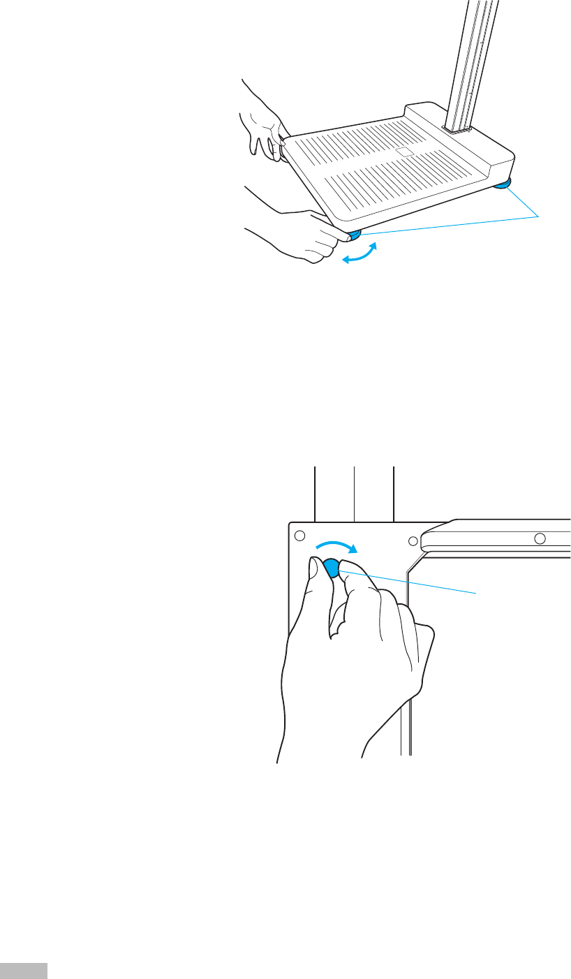
12. After placing the BSM170/170B on a at surface, the footplate is not level, use the footplate adjustment
screws to adjust until level.
* Leveling the equipment is necessary for accurate height measurements.
footplate leveling screws
13. When taking measurements with the BSM170/170B, the operator must move the measurement unit up and down
manually. By default, the adjustment screw is tight to keep the measurement unit from sliding down too freely.
If the screw is too tight, adjust the screw to the preferred tightness.
* By default, the adjustment screw is tight to keep the measurement unit from sliding down too freely. If the screw is too tight,
adjust the screw to the preferred tightness.
* If the screw is tightened too tight, the measurement unit may not move at all.
Measurement unit adjustment screws
11
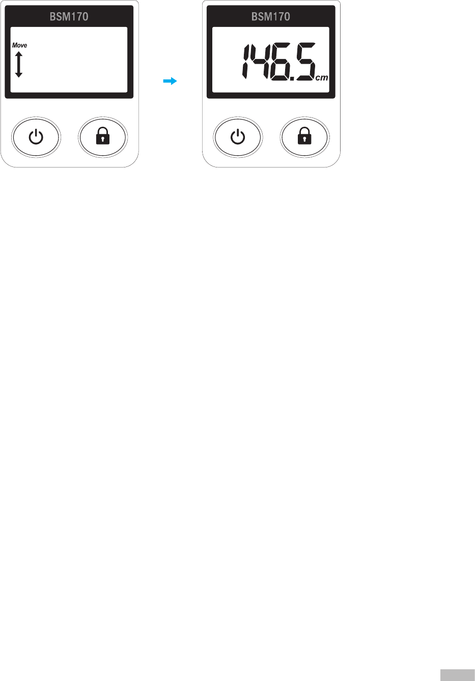
14. Turns on the BSM170/170B.
15. Move the measurement unit up or down until the ‘Move’ text disappears. The equipment will enter the
measurement standby mode and the display will change as shown below.
12
D. Stadiometer Settings
1. Requried Settings
1. After turning on the BSM170/170B, press and hold the button and the button simultaneously
for at least 3 seconds to enter the Setup menu.
c. Save changes by pressing the button.
2. In the Setup menu, set the measurement value hold time, beep, screen brightness, units, and offset value.
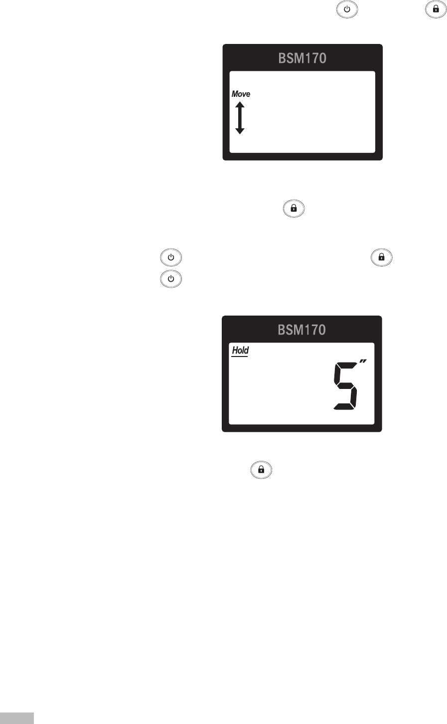
1) Measurement value hold time: When the button is pressed after a height measurement is recorded,
the value displayed will stay locked on the LCD screen for this amount of time, even if the measurement
unit is moved.
a. Use the button to move to ‘Hold’ and then press the button to select.
b. Use the button to set a hold time for the locked height value.
* The hold time can be set to off or on for anywhere between 1 to 10 seconds.
Measurement value hold time setup
13
c. Save changes by pressing the button.
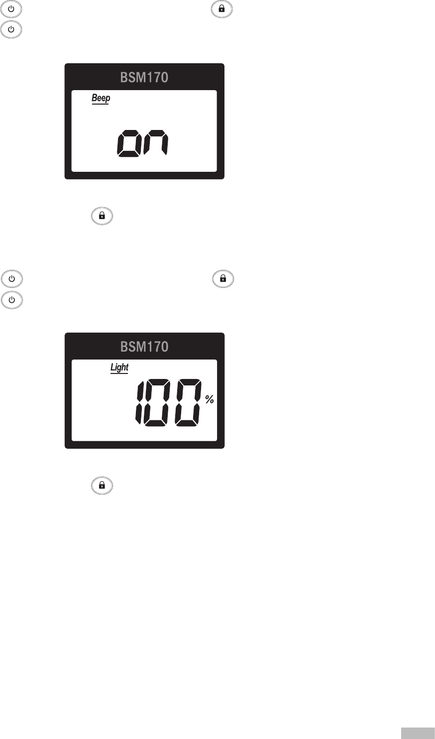
2) Beep: Enable or disable the beep alert.
a. Use the button to move to ‘Beep’ and then press the button.
b. Use the button to turn on or off the beep alert.
* Beep can be set to on or off.
Beep setup
c. Save changes by pressing the button.
3) Screen brightness: Brightness of the LCD screen.
a. Use the button to move to ‘Light’ and then press the button.
b. Use the button to set the screen brightness that is appropriate for the test environment.
* Screen brightness can be set to 100%, 50%, or off.
Screen brightness setup