Contents
- 1. User Manual Part 1
- 2. User Manual Part 2
User Manual Part 2
14
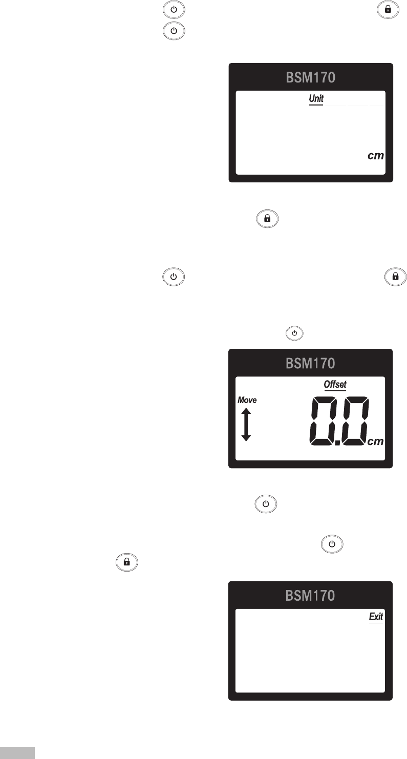
4) Unit: Units used for measurement.
a. Use the button to move to ‘Unit’ and then press the button.
b. Use the button to set the unit appropriate for the test environment.
* Unit can be set to be cm or feet and inches.
Unit setup
c. Save changes by pressing the button.
6) After conguring the BSM170/170B, press the button to move to ‘Exit’ and press the
button. BSM170/170B is now ready for use.
Offset value setup
5) Offset value: Setting an offset value allows height measurements to be adjusted automatically.
a. Use the button to move to ‘Offset’ and then press the button.
b. Move the measurement unit up or down to set an offset value appropriate for your test environment.
* Offset value can be set up to ±99.9cm.
* To reset the offset value to 0.0, press the button.
c. Save changes by pressing the button.

15
2. Optional Settings
1. After turning on the BSM170/170B, press and hold the button and the button on the
measurement unit simultaneously for at least 3 seconds to enter the Setup menu.
2. In the Setup menu, you can calibrate the equipment or reset factory default settings.
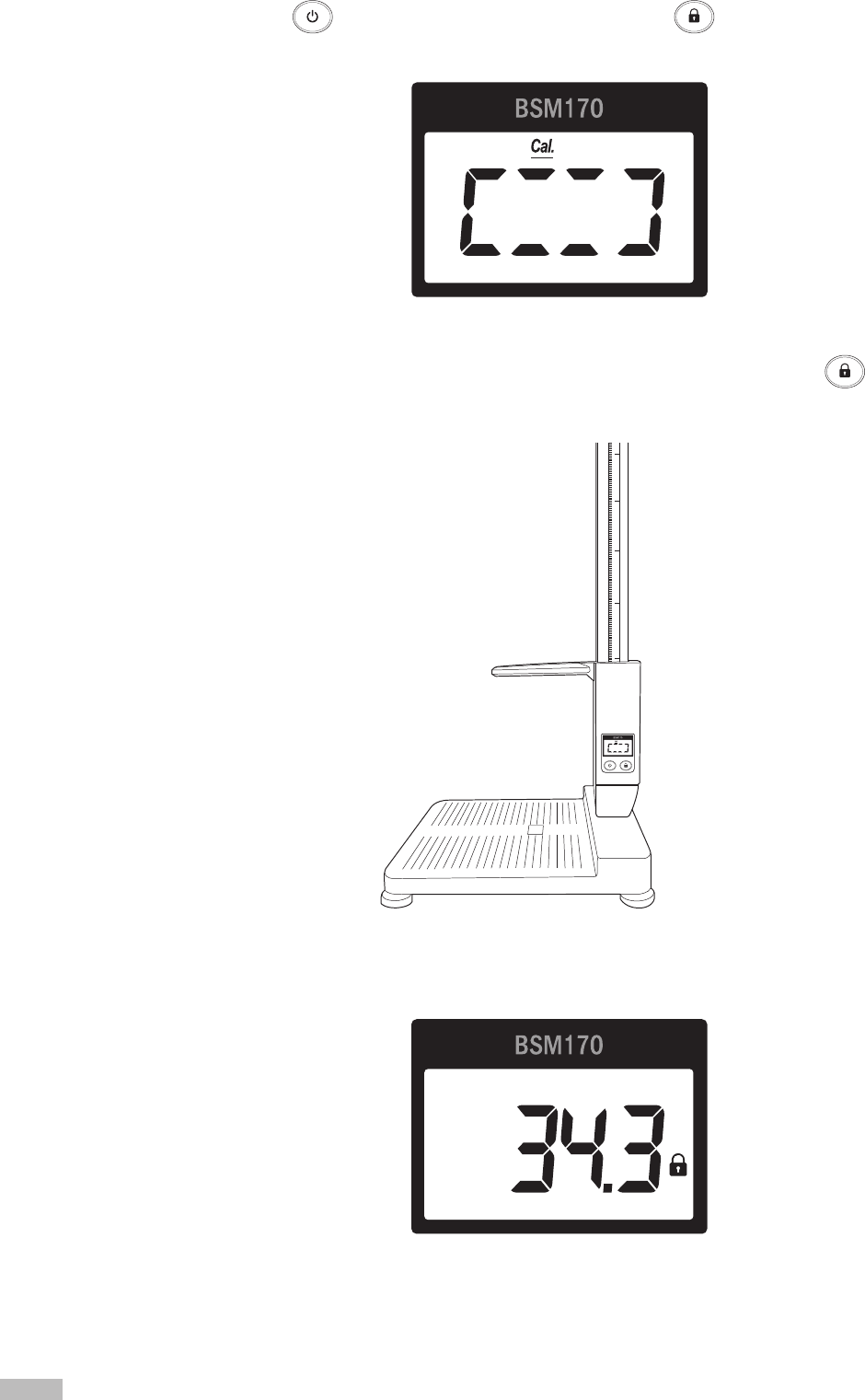
1) Calibration: The equipment can be calibrated to ensure correct measurement values.
a. Raise the measurement unit to eye level as illustrated below.
* The measurement unit should be at least a minimum of 92 cm off the footplate.
Right scales
Left scales
Calibration setup
b. Use the button to move to ‘Cal.’ and then press the button.
16
e. The number ‘34.3’ appears on the LCD screen.
c. Use the button to move to ‘Yes’ and then press the button.
Calibration will begin.
d. Lower the measurement unit all the way down of the footplate and press the button.
* The measurement unit must be lowered until it is resting against the footplate.
17
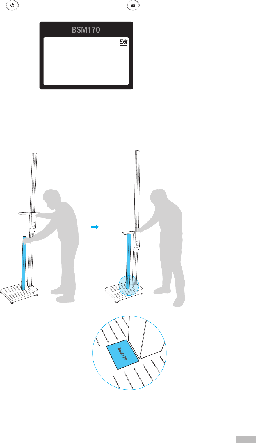
g. Erect the Test Jig provided at the logo on the footplate and lower the measurement unit so that
it touches the top of the Test Jig as illustrated below.
* The Test Jig must be positioned perpendicular to the footplate.
* The Test Jig must be positioned correctly.
f. Press the button to move to ‘Exit’ and then press the button. BSM170/170B is now
ready for use.
18
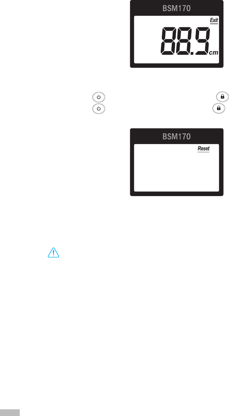
h. Check that the ̒ 88.9cm ̕ is shown on LCD screen of the measurement unit.
* If ̒ 88.9cm ̕ is not shown on the LCD screen(error range: ±0.1cm), please contact InBody.
Reset
2) Reset: Reset all settings to factory settings.
a. Use the button to move to ‘Reset’ and then press the button.
b. Use the button to move to ‘Yes’ and then press the button.
All stored settings will be reset.
E. Maintenance
DANGER
NOTECAUTION
참 조 주 의참 고 주 의
Caution
•
It may not be possible to take any measurements if the measuring tape has been damaged or dirtied.
•
It may not be possible to take any measurements if there is an excessive amount of shock placed on the
measurement unit.
•
The screw adjusting movement of the measurement unit along the Stand may be loosened according to
environmental changes and usage duration. Use the pressure adjusting screw on the rear of the measurement
unit to adjust the pressure appropriately.
•
Use batteries made by the same manufacturer.
•
Do not lean on the Stand or apply excessive shock to it.
•
When storing the BSM170/170B, remove the batteries and repackage.

19
II. Height Measurement
A. Precautionary Measurements
DANGER
NOTECAUTION
참 조 주 의참 고 주 의
Warning/Caution
•
If the equipment is unstable or unbalanced when you step on the footplate, use the footplate adjustment screws to
ensure that the equipment is level before taking measurements.
•
Take care when lowering the measurement unit to not catch your fingers.
•
Do not run around run around or play around the footplate. This may result in serious injury.
•
Children and people with limited mobility should be supervised or assisted when attempting to measure on the
BSM170/170B.
20
B. Measurement Instructions
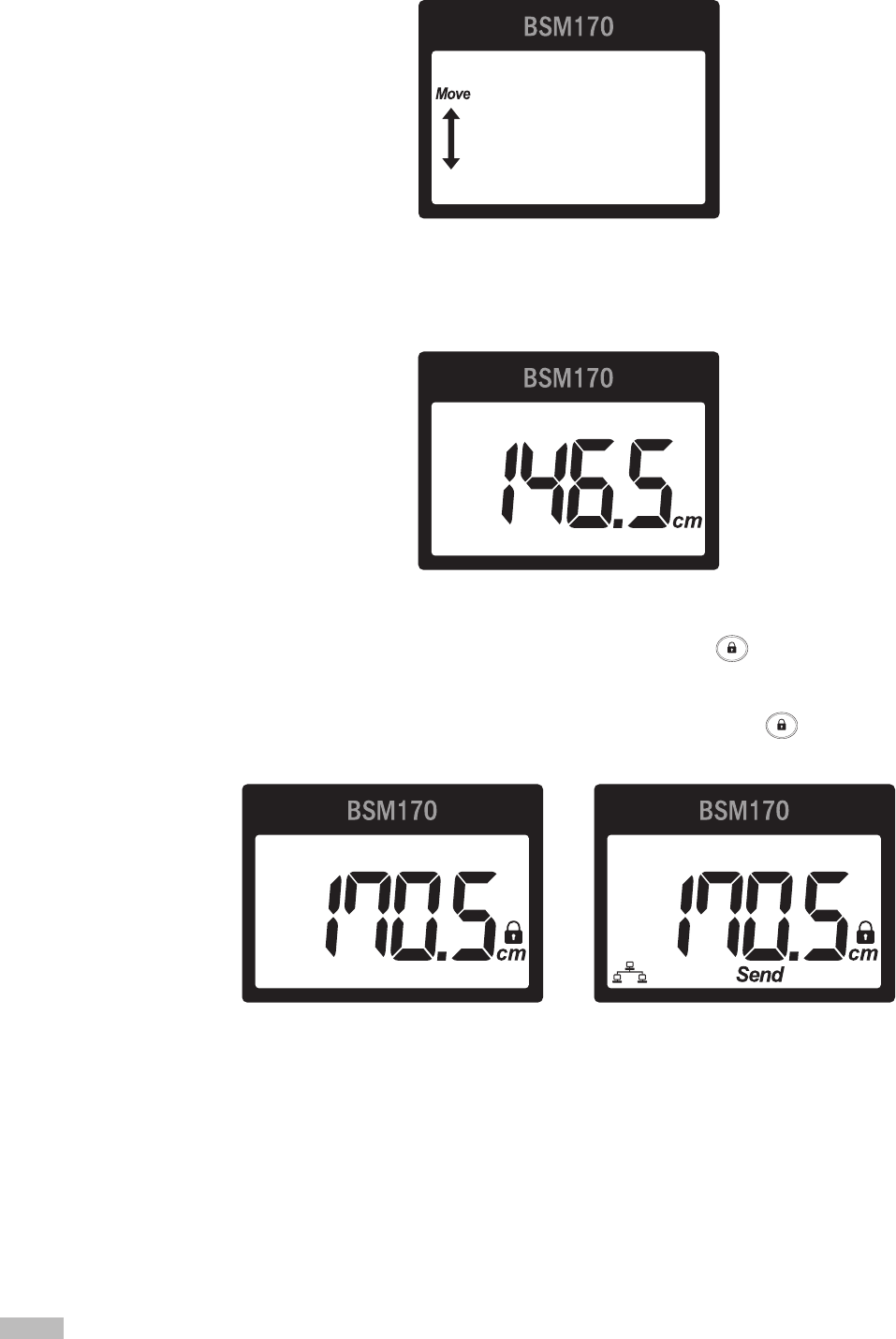
1. Move the measurement unit so that a number is displayed on the screen.
2. Step on the footplate barefooted and lower the measurement unit so that the upper part of the measurement
unit touches the examinee’s head. The height measurement is shown on the LCD screen, as illustrated below.
* If the measurement value hold feature has been enabled in Setup, pressing the button after desired measurement is
displayed on the LCD, locks the measurement for the set hold time.
* Only BSM170B can connect to the InBody via its integrated Bluetooth. Please refer to the InBody User's manual about
Bluetooth connection guide. If the BSM170B is connected to an InBody, pressing the button shows the 'send'
message on the LCD screen, as illustrated below, and transmits the measured value to the InBody.
<When not connected to InBody> <When connected to InBody>

21
C. Measurement Posture
The examinee must maintain proper posture to have accurate measurement results.
Tuck in the chin, stomach, and
chest, and look forward.
Put the arms down naturally.
Allow your backside to gently touch
the stand.
Touch the end of the footplate
with the heels.
Put both the feet together.
Do not bend the knees.
Keep the legs straight.
22
III.
Transportation and Storage
A. Repacking Instructions
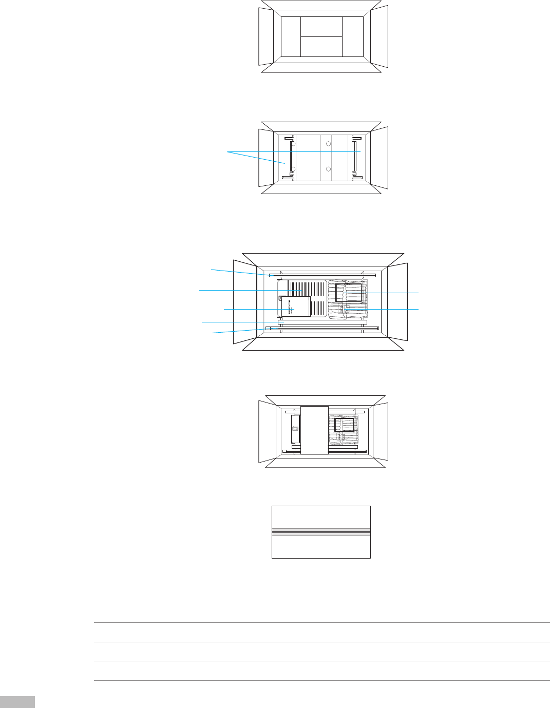
1. Prepare the BSM170/170B packaging box.
2. Place the paper pad on the bottom and put 2 small Polyethylene pads on both sides of the packaging box,
as illustrated below.
3. Position the disassembled components as illustrated below.
* Accessory box: measurement tape 1EA, footplate mounting screws 4EA, Stand mounting screws 4EA, AA batteries 4EA
4. Place 1 big Polyethylene pad over the footplate.
5. Close the packaging box and seal it with tape.
B.
Transportation and Storage Environment
The BSM170/170B should be transported or stored under the following conditions.
Stand (lower)
Stand (upper)
Footplate
User's manual
Test Jig
Accessory box
Measurement unit
Temperatures range -10 ~ 70℃
Relative humidity 10 ~ 80% RH (No Condensation)
Atmospheric pressure 50 ~ 106kPa
Polyethylene pads

23
IV.
Frequently Asked Questions
Even if no problems arise from the equipment, users may still have many questions, especially regarding clinical
procedures. A few more of the common questions and answers are listed below. If you encounter problems while
using the BSM170/170B or have questions concerning height measurement, please refer to the possible solutions below.
If your problem cannot be resolved from the following table, please contact InBody.
Question Answer
• My BSM170/170B does
not turn on.
• Batteries may need to be replaced.
* If the battery icon ( ) appears on the screen, replace the batteries as soon as possible.
• Height measurement
seems to be inaccurate.
• Check to see the BSM170/170B is level.
• Restart the BSM170.
• The measuring tape may be dirty. Wipe the measuring tape with a soft
tissue. Do not use cleaning solutions as they may damage the measuring
tape.
• Check if the measurement tape is protruding above the top of the Stand.
The measurement tape must be inserted all the way to the end of the stand.
• The arrow mark on the measurement tape must face downward so that,
when assembled, the ner gradation is visible on the left-hand side.
• The correct measurement position must be maintained. For details on the
measurement position, see ‘C. Measurement Position’ under ‘II. Height
Measurement’ in this user’s manual.
• The Stand is not secure or
stable.
• Check that the bottom and joint mounting bolts are fastened tightly.
• The measurement unit
is difcult to lower.
• Turn the adjustment screw on the rear of the measurement unit left or
right to adjust the tightness for smooth vertical movement of the
measurement unit.
* By default, high pressure is applied to keep the measurement unit from slipping down freely.
If the pressure weakens and the base begins to slip downward, turn the screw clockwise to
increase the pressure.
* If the screw is tightened too tightly, the measurement unit may not move at all.
• The measurement unit
is moved but the value
displayed on the LCD is
not changing.
• ‘Auto-lock’ may be enabled. See ‘D. Stadiometer Setup’ under
‘I. Stadiometer Installation’ of this User’s Manual to adjust ‘Auto-lock’.
• An error message is
shown on the LCD
screen.
• The measurement unit is moved too fast. The BSM170/170B also enters
standby mode if the measurement unit is idle for more then 2 seconds.
24
V. Others
* The BSM170/170B is registered for electromagnetic compatibility in accordance with the Framework Act on Telecommunications and
the Radio Waves Act.
* The BSM170/170B is designed, manufactured, and inspected according to h the quality assurance system of InBody. InBody complies
with the ISO9001 which are international quality management systems.
A. Exterior and Functions
The followings are names and functions of each part of the BSM170/170B.
* Please inspect each component of the BSM170/170B for damage prior to installation.
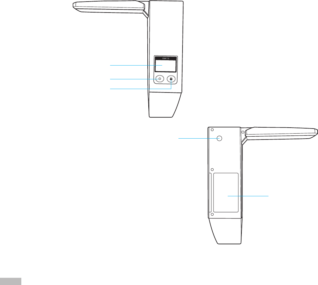
1. Measurement unit
❶
LCD screen: Shows height measurement values, and equipment connection status.
❷
On/Off button: Used for turning on/off the equipment.
❸
Lock button: Used to lock the measured height on the measurement unit. Allows for the measurement
unit to be moved without changing the value displayed on the LCD.
❹
Pressure adjustment bolt: Used to adjust the ease of movement of the measurement unit.
❺
Battery tray: Insert batteries (AA) here.
❶
❷
❸
❹
❺

25
2. Upper section
❶
Stand (upper): Upper part of the equipment Stand.
❷
Measurement tape: Used to adjust the footplate to be level for accurate measurements.
❸
Stand (lower): Lower part of the equipment Stand.
3. Lower section
❶
Stand insertion hole: The Stand is inserted here for assembly with the footplate.
❷
Footplate: The examinee steps on the footplate when having height measured.
❸
Leveling screws: Used to adjust the footplate to be level for accurate measurements.
❶
❷
❸
❶
❷
❸
26
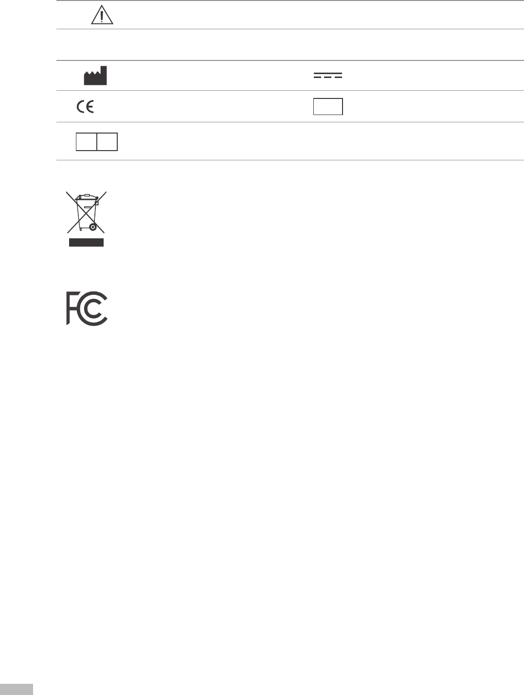
B. Symbols
SN
EC REP
1177
SN
EC REP
1177
Safety Symbol
Warning/Caution
Other Symbols
Manufacturer Direct current
European Conformity Serial number
Authorized representative in the
EUROPEAN COMMUNTY
SN
EC REP
1177
SN
EC REP
1177
SN
EC REP
1177
Disposal of old Electrical & Electronic Equipment
(Application in the European Union and other European countries with separate collection system.) This
symbol indicates that this product shall not be treated as household waste. Instead, it shall be handed over to the
applicable collection point for the recycling of electrical and electronic equipment. By ensuring this product is
disposed of correctly, you will help prevent potential negative consequences for the environment and human
health, which could otherwise be caused by inappropriate waste handling of this product. For more detailed
information about recycling this product, please refer to local governing ordinances and recycling plans.
This device complies with part 15 of the FCC Rules. Operation is subject to the following two conditions: (1)
This device may not cause harmful interference, and (2) this device must accept any interference received,
including interference that may cause undesired operation.
WARNING
This equipment may generate or use radio frequency energy. Change or modification to this
equipment may cause harmful interface unless the modifications are expressly approved in the
instruction manual. The user could lose the authority to operate this equipment if an unauthorized
change or modification is made.
The antenna must be installed such that 20cm is maintained between the antenna and users.
Note
This equipment has been tested and found to comply with the limits for a Class B digital device,
pursuant to part 15 of the FCC Rules. These limits are designed to provide reasonable protection
against harmful interference in a residential installation. This equipment generates, uses, and can
radiate radio frequency energy and, if not installed and used in accordance with the instructions, may
cause harmful interference to radio communications. However, there is no guarantee that interference
will not occur in a particular installation. If this equipment does cause harmful interference to radio
or television reception, which can be determined by turning the equipment off and on, the user is
encouraged to try to correct the interference by one or more of the following measures:
- Reorient or relocate the receiving antenna.
- Increase the separation between the equipment and receiver.
- Connect the equipment into an outlet on a circuit different from that to which the receiver is connected.
- Consult the dealer or an experienced radio/TV technician for help.
27
C. Specications
Intended use
Hand-operated mechanical stadiometer
Measurement item
Height
Heights measured
350 ~ 2100mm (1 ft. 1.78 in. ~ 6 ft. 10.67 in.)
Height measurement
error range
± 1mm (± 0.04 in.)
Result display
Customized LCD
Height measurement Manual measurement
Measurement unit Select between ‘cm’ and ‘inch’
Power DC 6V (4 AA-sized 1.5V batteries)
External interface Bluetooth *Only for BSM170B
Dimension
15.35 (W) × 19.70 (L) × 86.23(H): inch
390 (W) × 500.6 (L) × 2190.4 (H): mm
Equipment Weight 8.5kg
Operation Environment 10 ~ 40℃(50 ~ 104℉ ), 30 ~ 75% RH, 70 ~ 106kPa
Storage Environment -10 ~ 70℃ (4 ~ 158℉), 10 ~ 80% RH, 50 ~ 106kPa (No Condensation)
* Specications may change without prior notice.

www.inbody.com
ⓒ
2014 InBody Co., Ltd. All rights reserved. BM-ENG-E9-B-140827