InBody BSM170B Stadiometer User Manual Part 2
InBody Co., Ltd. Stadiometer Part 2
UserManual.wiki
>
InBody
>
BSM170B User Manual
>
User Manual Part 2
Contents
1.
User Manual Part 1
2.
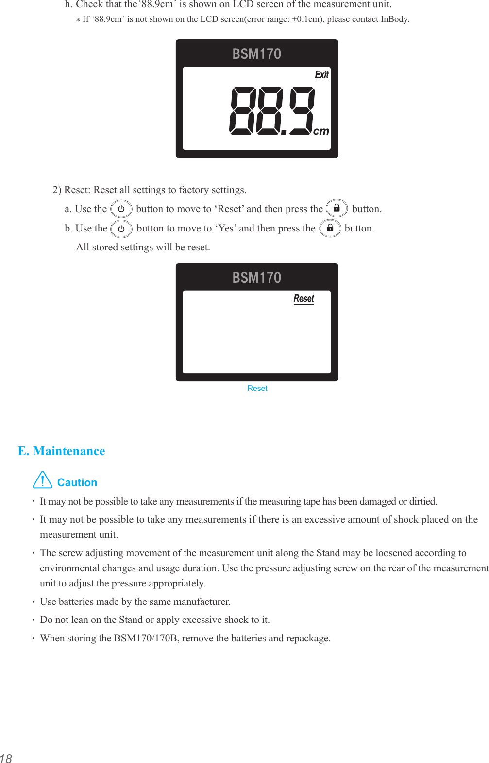
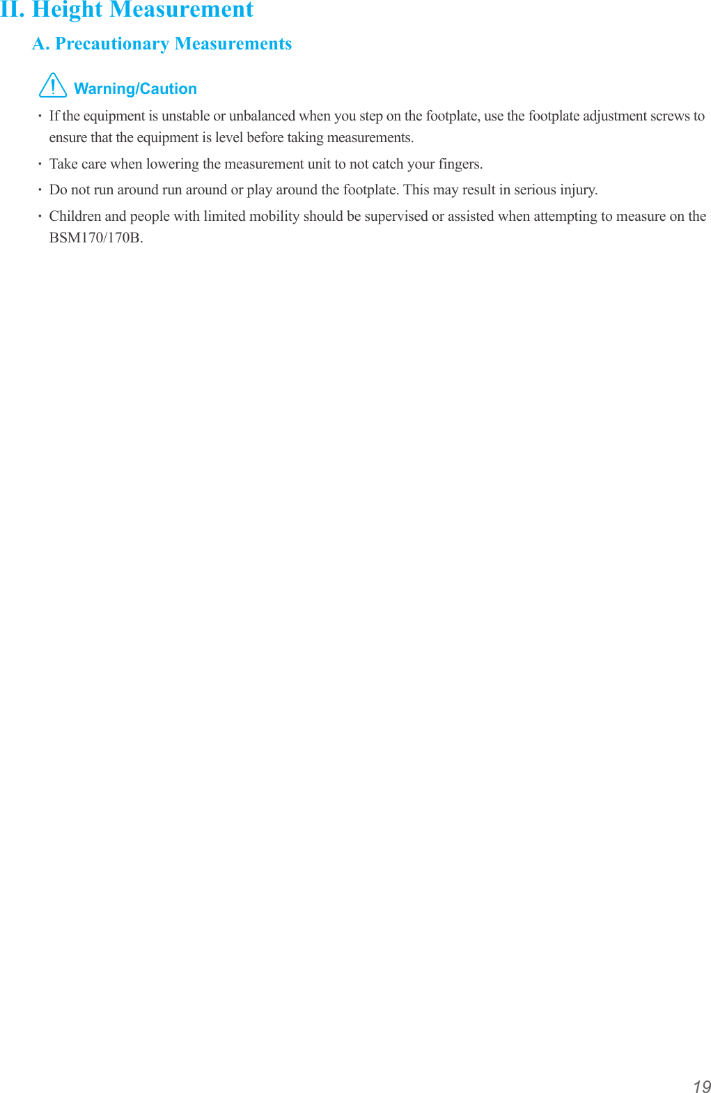
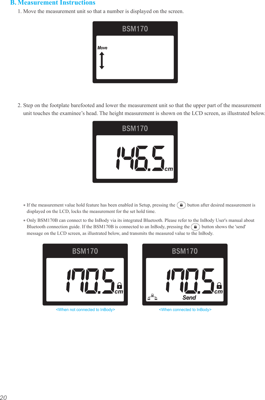
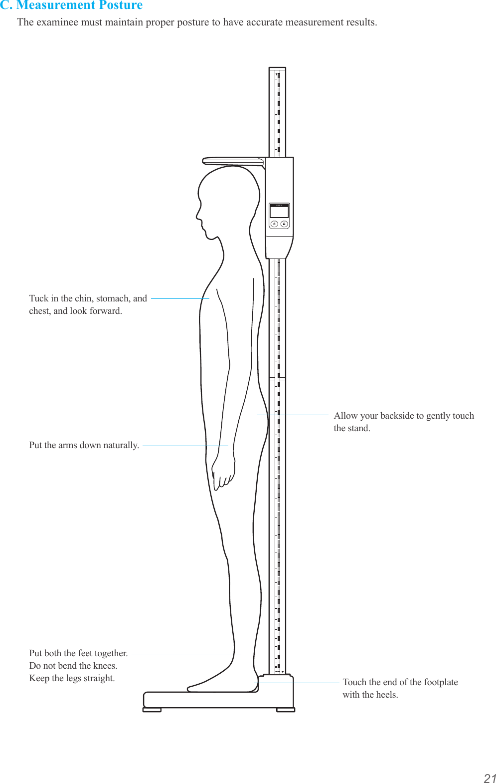
User Manual Part 2
User Manual Part 2
Navigation menu
Upload a User Manual
Namespaces
Wiki Guide
HTML
PDF
Info
Views
User Manual
Discussion / Help
Navigation