Ingenu ULPAP310 2.4GHz Spread Spectrum Device User Manual Access Point Product Specification
On-Ramp Wireless 2.4GHz Spread Spectrum Device Access Point Product Specification
Ingenu >
Contents
- 1. User Manual I
- 2. User Manual II
User Manual II

On-Ramp Wireless Confidential and Proprietary. This document is not to be used, disclosed, or distributed to
anyone without express written consent from On-Ramp Wireless, Inc. The recipient of this document shall respect
the security of this document and maintain the confidentiality of the information it contains. The master copy of
this document is stored in electronic format, therefore any hard or soft copy used for distribution purposes must
be considered as uncontrolled. Reference should be made to On-Ramp Wireless, Inc. to obtain the latest revision.
Access Point
Product Specification

On-Ramp Wireless, Inc.
10920 Via Frontera, Suite 200
San Diego, CA 92127
U.S.A.
Copyright © 2015 On-Ramp Wireless, Inc.
All Rights Reserved.
The information disclosed in this document is proprietary to On-Ramp Wireless, Inc. and is not to be used or
disclosed to unauthorized persons without the written consent of On-Ramp Wireless, Inc. The recipient of this
document shall respect the security of this document and maintain the confidentiality of the information it
contains. The master copy of this document is stored in electronic format, therefore any hard or soft copy used for
distribution purposes must be considered as uncontrolled. Reference should be made to On-Ramp Wireless, Inc.
to obtain the latest version. By accepting this material the recipient agrees that this material and the information
contained therein is to be held in confidence and in trust and will not be used, copied, reproduced in whole or in
part, nor its contents revealed in any manner to others without the express written permission of On-Ramp
Wireless, Inc.
On-Ramp Wireless, Inc. reserves the right to make changes to the product(s) or information contained herein
without notice. No liability is assumed for any damages arising directly or indirectly by their use or application.
The information provided in this document is provided on an “as is” basis.
This document contains On-Ramp Wireless, Inc. proprietary information and must be shredded when discarded.
This documentation and the software described in it are copyrighted with all rights reserved. This documentation
and the software may not be copied, except as otherwise provided in your software license or as expressly
permitted in writing by On-Ramp Wireless, Inc.
Any sample code herein is provided for your convenience and has not been tested or designed to work on any
particular system configuration. It is provided “AS IS” and your use of this sample code, whether as provided or
with any modification, is at your own risk. On-Ramp Wireless, Inc. undertakes no liability or responsibility with
respect to the sample code, and disclaims all warranties, express and implied, including without limitation
warranties on merchantability, fitness for a specified purpose, and infringement. On-Ramp Wireless, Inc. reserves
all rights in the sample code, and permits use of this sample code only for educational and reference purposes.
This technology and technical data may be subject to U.S. and international export, re-export or transfer
(“export”) laws. Diversion contrary to U.S. and international law is strictly prohibited.
RPMA® (Random Phase Multiple Access) is a registered trademark of On-Ramp Wireless, Inc.
Other product and brand names may be trademarks or registered trademarks of their respective owners.
Access Point Product Specification
014-0030-00 Rev. G
December 7, 2015

iii 014-0030-00 Rev. G
Contents
1 Introduction ........................................................................................................................ 1
1.1 AP Product Configurations .................................................................................................... 1
1.2 References ............................................................................................................................ 2
2 Product Specification Overview ........................................................................................... 3
2.1 AP Product Specifications ..................................................................................................... 3
2.2 RF Subsystem Block Diagram ............................................................................................... 6
3 Electrical Characteristics ...................................................................................................... 9
3.1 Power over Ethernet (PoE) .................................................................................................... 9
3.2 Channel Numbering .............................................................................................................. 9
3.3 Current and Power Consumption ........................................................................................ 10
3.4 Lightning/ESD Test Compliance ......................................................................................... 10
4 Compliance Certifications .................................................................................................. 11
4.1 FCC/IC Certification .............................................................................................................. 11
4.2 ETSI Certification ................................................................................................................. 11
4.3 ETSI RFID Certification........................................................................................................ 12
4.4 Japan Certification ............................................................................................................... 13
4.5 Hong Kong Certification ...................................................................................................... 13
5 GPS ................................................................................................................................... 14
6 Transmitter Information .................................................................................................... 15
6.1 Transmit Spectral Shape ..................................................................................................... 15
6.2 Load VSWR Effects on TX Power Accuracy ......................................................................... 15
7 Hardware Requirements .................................................................................................... 16
7.1 Antenna Requirements ....................................................................................................... 16
7.2 RF Cable Requirements ........................................................................................................ 17
7.3 Ethernet Speed and Cable Requirements ............................................................................. 17
7.4 LEDs .................................................................................................................................... 17
Appendix A Access Point Mechanical Drawing ....................................................................... 18
Appendix B Abbreviations and Terms ................................................................................... 19

Access Point Product Specification Contents
iv 014-0030-00 Rev. G
Figures
Figure 1. Access Point ................................................................................................................ 1
Figure 2. AP Radio Block Diagram for FCC/IC ............................................................................. 7
Figure 3. AP Radio Block Diagram for ETSI/Japan ....................................................................... 8
Figure 4. Spectral Shape—Linear and Compressed .................................................................. 15
Figure 5. Access Point Mechanical Drawing .............................................................................. 18
Tables
Table 1. Basic AP Specifications.................................................................................................. 3
Table 2. Summary of AP Product Specifications ......................................................................... 3
Table 3. Electrical Protection ...................................................................................................... 9
Table 4. Channel Numbers vs. Frequency ................................................................................... 9
Table 5. Typical AP Current and Power Consumption ............................................................... 10
Table 6. FCC and IC Compliance Tests for Certification ............................................................. 11
Table 7. ETSI Emissions EN 300-440-2 Compliance Tests for Certification ................................. 11
Table 8. ETSI Immunity 301-489-2 Compliance Tests for Certification ...................................... 11
Table 9. Countries in which the AP is certified for ETSI RFID .................................................... 12
Table 10. ETSI RFID Emissions EN 300-440-2 V1.4.1 Compliance Tests for Certification ............ 13
Table 11. Compliance Tests for Certification in Japan ................................................................ 13
Table 12. Summary of TX Gain/Power Variation Due to Load VSWR ........................................ 15
Table 13. Antennas for FCC Configuration ................................................................................ 16
Table 14. Antennas for ETSI Configuration ............................................................................... 16
Table 15. Antennas for ETSI RFID Configuration ....................................................................... 16
Table 16. Antennas for Japan Configuration .............................................................................. 17

v 014-0030-00 Rev. G
Revision History
Revision
Release Date
Change Description
A
October 10, 2011
Initial release.
B
November 2, 2011
Updated with information for operating at the ETSI RFID configuration for
the Access Point.
C
April 13, 2012
Updated product specifications, regulatory certifications, lightning/ESD
test compliance, transmitter information, and antenna requirements. Also
added Access Point mechanical drawing.
D
September 14, 2012
Updated:
The product specifications table
The L-com antenna information for the ETSI configuration
Added:
Model numbers for various AP configurations
An LED section in the Hardware Requirements chapter
E
September 26, 2012
Updated the product specifications table with regulatory compliance
information.
F
July 31, 2013
Updated the product specifications table to include the IEEE 802.15.4k
requirement.
Clarified some product specifications in chapter 2.
Updated the ORW logo
Updated the AP photo, AP references, and model number.
G
December 7, 2015
Updated for new branding.
Updated model number.
Added Sectorized AP definition and block diagram and FCC ID
Added Dual Latency AP definition and block diagram and FCC/IC ID
1 014-0030-00 Rev. G
1 Introduction
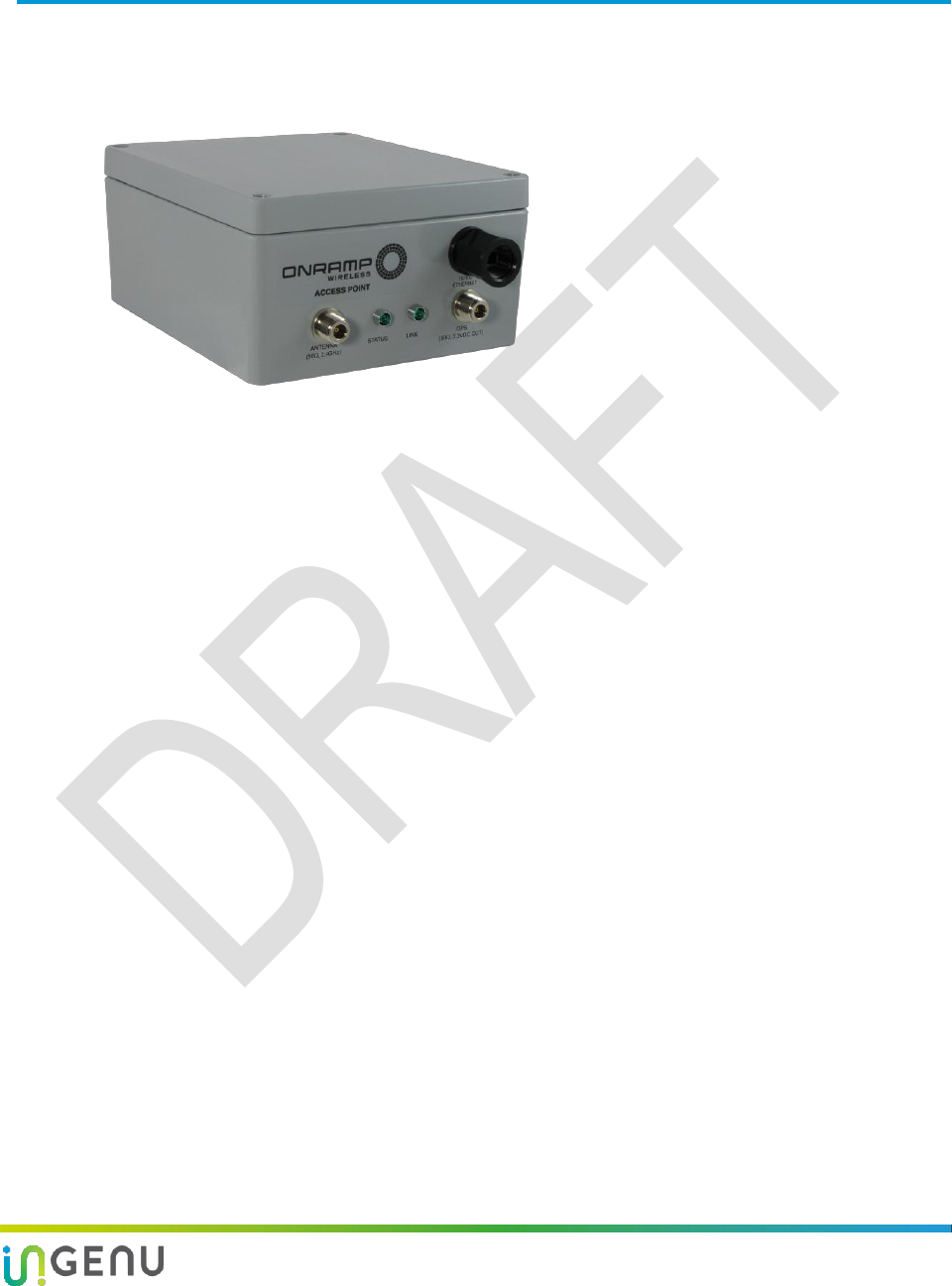
This document provides an overview of the Access Point and is shown below. It also provides
product specifications, characteristics, and requirements for the Access Point (AP).
Figure 1. Access Point
1.1 AP Product Configurations
The following AP product configurations are currently available for worldwide markets. The
Element Management System (EMS) software is used during network configuration and setup
of the AP. This software automatically configures the maximum allowed TX power levels (EIRP)
taking into account regulatory domain, antenna gain, and cable loss.
1. FCC/IC Configuration (Model: ULPAP110)
The Federal Communications Commission (FCC)/Industry Canada (IC) configuration
supports transmit power requirements up to 30 dBm conducted, 36 dBm EIRP, with 38
channels available. It contains a cavity filter for high out-of-band rejection. It is EMC
compliance certified to FCC Part 15C Section 15.247 and IC RSS 210 Issue 7.
2. FCC Sectorized AP (Model: ULPAP210)
The Sectorized AP Configuration is limited to 26 dBm conducted transmit power, up to 43
dBm EIRP, from (2402-2475.63MHz). This configuration requires two ULPAP110 APs
professionally installed, with each AP connected to a 17dBi 90 degree antennas.
3. FCC/IC Dual Latency Configuration (Model: ULPAP310)
The ETSI Dual Latency configuration is made up of two ULPE100, one for each sub-band,
connected to the antenna through a diplexer. The software configures each sub-band
channel to a maximum of 30dBm at the antenna port. The antenna gain must be such that
the maximum radiated power is 36dBm EIRPper channel. The system processess two
independent information streams through the diplexer to the antenna. Each diplexer sub-
band allows 3 or 4 one MHz channels. There are four possible sub-bands. The system is
professionally installed.
4. ETSI Standard Configuration (Model: ULPAPE100)
The European Telecommunications Standards Institute (ETSI) configuration is limited to
10 dBm of conducted transmit power, up to 10 dBm EIRP, with 40 channels available. It

Access Point Product Specification Introduction
2 014-0030-00 Rev. G
does not have an internal cavity filter. It is EMC compliance certified to ETSI-301-489 and
ETSI-300-440.
5. ETSI RFID Configuration (Model: ULPAPE100)
The ETSI Radio Frequency Identification (RFID) configuration is limited to 10 dBm
conducted transmit power, up to 27 dBm EIRP, with three channels available (2446-
2454MHz). This configuration does not have an internal cavity filter. The hardware is the
same as the ETSI standard version; however the software is configured to accommodate
the power and frequency specifics. The AP is EMC compliance certified to ETSI-301-489,
ETSI-300-440, and EU REC 70-03 (Annex 11). APs are permitted to operate under EU REC
70-03 (Annex 11) in France, Germany, Ireland, Spain, Switzerland–Liechtenstein, and United
Kingdom.
6. Japan Configuration (Model: ULPAPE100)
The Japan configuration is limited to 10 dBm conducted transmit power and up to 12 dBm
EIRP with 41 channels available. It does not have an internal cavity filter. The hardware is
the same as the ETSI standard version, however the software is configured to
accommodate the power and frequency specifics. It is EMC compliance certified to
Japanese Radio Law; Item 19 of Article 12 (category WW) and ARIB STD-T66.
7. Hong Kong Configuration (Model: ULPAP110)
Hong Kong allows two different paths to certification utilizing rules for either China or
FCC/IC. The FCC/IC certification rules were used to certify the AP. Certification in Hong
Kong is based on the same information and tests provided for FCC/IC certification. The
Hong Kong version of the AP is identical to the FCC/IC version so all information is the
same. As with the FCC/IC configuration, the Hong Kong version supports transmit power
requirements up to 30 dBm conducted, 36 dBm EIRP, with 38 channels available. It contains
a cavity filter for high out-of-band rejection. It is EMC compliance certified to FCC Part 15C
Section 15.247 and IC RSS 210 Issue 7.
1.2 References
The following document provides additional details about the AP.
AP Deployment Guide (PN: 010-0006-00 for 1.4 system and PN: 010-0021-00 for 2.1 system)
Provides network planning considerations, installation and software configuration guidelines
and instructions, and maintenance information for the AP as a part of the RPMA network which
enables remote wireless communication.
3 014-0030-00 Rev. G
2 Product Specification Overview
2.1 AP Product Specifications
The following table provides basic specification information for the AP.
Table 1. Basic AP Specifications
Size
Inches: 9.1”H x 8.1”W x 4.5”D
Millimeters: 232mm H x 202mm W x 111mm D
Maximum Weight
Pounds: 9.6
Kilograms: 4.35
Operating Environment
Outdoors or indoors
Power Dissipation
17 Watts (maximum)
Antenna Connector
Type N, female
GPS Connector
Type N, female
GPS Antenna Type
Powered
Data and Power Connector
RJ45 (POE)
Product specifications are summarized in the following table. Where available, additional
information is provided for some specifications; refer to the Link column.
Table 2. Summary of AP Product Specifications
Requirement Description
Requirement
Comments
Link
General
Product Lifetime
> 10 years
Enclosure
IP66
Signal Modulation
DSSS-ODBPSK
Direct-Sequence Spread
Spectrum Orthogonal Differential
BPSK
Multiple Access Scheme
RPMA
Random Phase Multiple Access
PHY/MAC Standard
IEEE 802.15.4k
Frequency Range by market:
FCC/IC version
ETSI Standard version
ETSI RFID version
Japan version
Frequency
2.402 – 2.475.63 GHz
2.402 – 2.479.61 GHz
2.446 – 2.454 GHz
2.402 – 2.481.60 GHz
Channels
CH1 – CH38
CH1 – CH40
CH24 – CH26
CH1 – CH41
Frequency Channel Step Size
1.99 MHz
See section 3.2 for exact
channels.
3.2

Access Point Product Specification Product Specification Overview
4 014-0030-00 Rev. G
Requirement Description
Requirement
Comments
Link
Operating Temperature
Range*
-40C – +80C
Ambient, not including solar
loading
Operating Temperature Rate
of Change*
-10C – +40C
Constant rate of change
measured over 1 hour.
Storage Temperature Range*
-40C – +85C
Humidity**
5% – 95%
Non-condensing
ESD, EN 61000-4-2
+ 16.5 kV Air Discharge
+ 9 kV Contact Discharge
On any exposed point of an
installed product.
Sine Vibration*
Operating
Non-operating
5 – 200 Hz, 4 m/s2
5 – 200 Hz, 2 m/s2
Random Vibration*
Operating
Non-operating
5 – 100 Hz, 1.5 Grms
5 – 100 Hz, 1.06 Grms
Shock*
Operating
Non-operating
40 G, Half Sine
30 G, Half Sine
Operating Condensation
Cycle**
50 – 98%
FCC/IC Requirements
15.247, 15.207, 15.215
RSS210e
Single AP FCC ID: XTE-
ULPAP110
IC Emissions Designation:
2M48G1D
4
FCC Requirements
15.247, 15.207, 15.215
Sectorized AP,
FCC ID: XTE-ULPAP210
4
FCC/IC Requirements
15.247, 15.207, 15.215
RSS210e
Dual Latency AP,
FCC ID: XTE-ULPAP310
IC ID: 8655A-ULPAP310
IC Emissions Designation:
2M48G1D
4
ETSI Requirements
300 440-1 and 440-2
301 489-1
IEC/EN/UL/CSA 60950-1
Compliance tests performed.
Documents on file, available upon
request.
4.2
Japan Requirements
Japanese Radio Law; Item 19 of
Article 12
Compliance tests performed.
Category WW, Test Report
R83818.
Access Point Capacity
Typical: 4,000 to 16,000
Maximum: 64,000
The number of nodes an AP can
support is dependent on the
application.
Data Rate
60 kbps
Measured as throughput at each
data point.
Power Source Voltage Range
(PoE)
38 – 72 VDC
Nominal 48 VDC Power Over
Ethernet.

Access Point Product Specification Product Specification Overview
5 014-0030-00 Rev. G
Requirement Description
Requirement
Comments
Link
Current Consumption
0.35A maximum
@ 48 VDC
See section 3.3 for details.
3.3
GPS Power
3.3 VDC @ 50 mA maximum
over coaxial cable
DC power supplied on GPS RF
connector.
5
Transmitter Related
Transmit Power Range
0 – 16 dBm (LP)
16 – 30 dBm (HP)
Referenced to AP N-connector.
Switchover point (16 dBm) is
approximate.
Transmitter Rated Power by
market (Country: Agency):
United States: FCC
Canada: IC
Europe: ETSI
Europe: ETSI (RFID)
Japan: TELEC
Hong Kong: OFTA
South Africa: ICASA
Brazil: ANATEL
Korea: RRA
Singapore: IDA
Macau: DSRT
Maximum TX EIRP:
36 dBm
36 dBm
10 dBm
27 dBm
12 dBm
36 dBm
10 dBm
26 dBm
10 dBm
20 dBm
20 dBm
Modulated conditions.
ETSI is the default choice for all of
Europe.
ETSI RFID is only allowed in
certain countries of the EU***.
Requires quad-sector antenna
(not Omni).
Peak to Average Ratio
2.9 dB
Signal Bandwidth
1 MHz
BT Factor
0.46
TX Spectral Bandwidth
2.32 MHz
99% bandwidth (-20 dB each side)
6.1
ACPR
≤ -30 dBc
Spec and test method comes from
FCC 15.247(d).
Harmonics
≤ -47 dBm
At any TX power level. Note
harmonics fall into FCC restricted
bands.
Transmit Power Level
Accuracy
≤ 1.7 dB
Estimated sum of all contributors.
Normal link mode (closed loop).
Transmitter Spurious Outputs
In-band but >1 MHz offset
30 MHz to 2400 MHz
2480 MHz to 8000 MHz
< -45 dBm
< -70 dBm
< -70 dBm
At any TX power level. Applies to
spurious, not ACPR or harmonics.
Load VSWR Range
1.4:1
( ≤ -15dB RL)
Exceeding this range influences
power accuracy.
6.2
Customer RF Cables Loss
Range
FCC: 0 dB to 3 dB
Others: 0 dB to 5 dB
GPS: 0 dB to 5 dB
Range of acceptable cable losses
connecting the AP to its
respective antenna.
7.2
Customer Ethernet Cable
Length
≤ 100 meters
Maximum length for emissions
compliance.
7.3

Access Point Product Specification Product Specification Overview
6 014-0030-00 Rev. G
Requirement Description
Requirement
Comments
Link
Receiver Related
Receive Sensitivity:
FCC/IC (with cavity filter)
ETSI/Japan (no cavity filter)
-140 dBm
-142 dBm
Referenced to AP N-connector
Maximum Receive Signal
Level
-30 dBm
Referenced to AP N-connector
Noise Figure
7 dB nominal
< 8 dB maximum
Referenced to AP N-connector,
FCC configuration (including CF)
Synthesizer Related
Precision Reference
Frequency
26 MHz
High stability VCTCXO is used,
GPS referenced
Frequency Accuracy
(Test mode, not GPS locked)
1 ppm
0.25 ppm
1 ppm
Initial tolerance.
Over temperature range.
Aging in first year.
Frequency Accuracy
(Normal mode, GPS locked)
0.05 ppm
GPS required for field
deployment. The GPS system
provides precision 1 pps timing
that allows the AP to meet the
demanding 0.05 ppm required
by the AP for communication.
Digital Clocks
26 MHz for digital, RF, AFE
33.33 MHz for CPU PLL
25 MHz for Ethernet
11.0592 MHz for UART
* Referenced standard: ETSI EN 300 019-2-4 V2.2.2 (2003-04)
** Referenced standard: IEC 60068-2-30 (Third Edition)
*** As of September 2012 the countries currently approving ETSI RFID power levels for the AP include
France, Germany, Ireland, Liechtenstein, Spain, Switzerland, and United Kingdom.
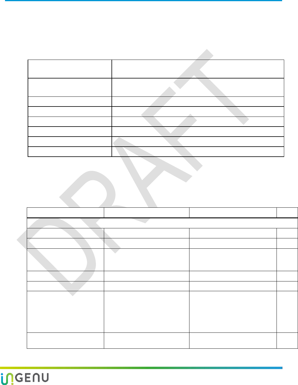
2.2 RF Subsystem Block Diagram
The AP RF subsystem operates as a half-duplex transceiver. The SPDT switches allow
connection from the antenna to one of three paths:
TX high power
TX low power
RX
The Cavity Filter is only used in the FCC/IC configuration, specifically to avoid the 2483 MHz
Restricted Band when near max power. It also provides excellent out-of-band rejection.
Access Point Product Specification Product Specification Overview
7 014-0030-00 Rev. G
Maxim
2830
RX
Balun-BPF
SPDT
Switch
Chip
LPF Chip
LPF
SPDT
Switch
SPDT
Switch Cavity
Filter
FE
Match
SMA
SMA
Cable
SMA
Cable
Box
Customer
Cable
N type
TX
Balun
PA
Chip
LPF
Tee
Pad
Figure 2. AP Radio Block Diagram for FCC/IC
Gateway/
Controller
Sectorized AP
Maxim
2830
RX
Balun- BPF
SPDT
Switch
Chip
LPF Chip
LPF
SPDT
Switch
SPDT
Switch FE
Match
SMA
Cable
Box
Customer
Cable
N type
TX
Balun
PA
Chip
LPF
Tee
Pad
BASEBAND
#1
Sector 1
Cavity
Filter
Maxim
2830
RX
Balun- BPF
SPDT
Switch
Chip
LPF Chip
LPF
SPDT
Switch
SPDT
Switch
Cable
Box
Customer
Cable
N type
TX
Balun
PA
Chip
LPF
Tee
Pad
BASEBAND
#2
Sector 2
FE
Match Cavity
Filter
SMA
Figure 3: Sectorized AP Block Diagram
Access Point Product Specification Product Specification Overview
8 014-0030-00 Rev. G
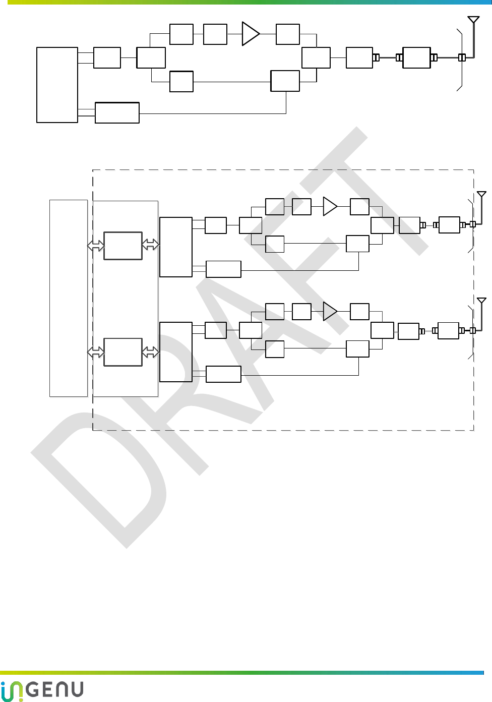
Gateway/
Controller
Dual Latency AP
System Boundary
RF
RX
SPDT
Switch
Chip
LPF
Chip
LPF
SPDT
Switch
SPDT
Switch
FE
Match
SMA
Cable
Box N type
TX
Balun
PA
Chip
LPF
Tee
Pad
Base Band #1
High
Capacity
Balun - BPF
Transceiver
RF
RX
SPDT
Switch
Chip
LPF
Chip
LPF
SPDT
Switch
SPDT
Switch
FE
Match
SMA
Cable
Box N type
TX
Balun
PA
Chip
LPF
Tee
Pad
Base Band #2
Low
Latency
Balun - BPF
Transceiver
32KHz
11.0592MHz
26MHz
33MHz
73MHz
83MHz
166MHz
333Mhz
666Mhz
26MHz
2400MHz
26MHz
2400MHz
CH1
Diplexer
CH2
30dBm/
Channel
Figure 4: Dual Latency Block Diagram
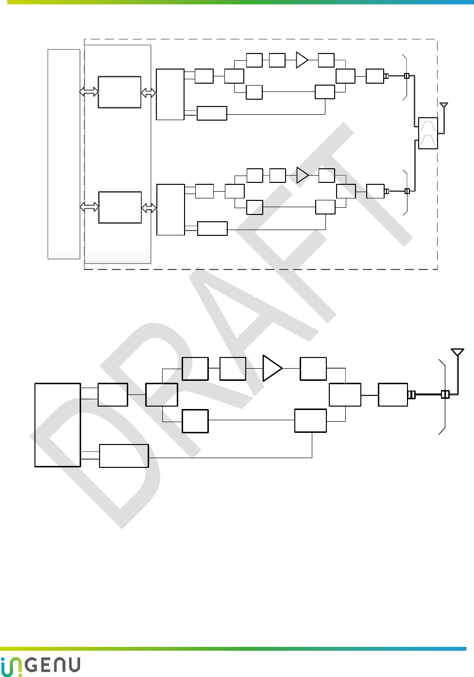
Maxim
2830
RX
Balun-BPF
SPDT
Switch
Chip
LPF Chip
LPF
SPDT
Switch
SPDT
Switch FE
Match
SMA
Cable
Box
Customer
Cable
N type
TX
Balun
PA
Chip
LPF
Tee
Pad
Figure 5. AP Radio Block Diagram for ETSI/Japan
9 014-0030-00 Rev. G
3 Electrical Characteristics
3.1 Power over Ethernet (PoE)
The nominal 48VDC on the Ethernet cable is separated from the data and regulated with a
switching power supply to 5.0VDC. This printed circuit board is equipped with lightning
protection, surge protection, and differential and common mode filtering. It also includes a
tamper protection device that will report to the system if the box cover has been opened.
NOTE: The AP is not 802.3AF or 802.3AT compliant. It requires a dedicated passive injector
and cannot be powered directly from most PoE switches.
Table 3. Electrical Protection
Surge Life
(@500A
10/1000μs)
Nominal Impulse
Discharge Current
(8/20μs)
Nominal AC
Discharge Current
(10x1sec @50-60Hz)
Max Impulse Discharge
Current
(1 Application @ 10/350μs)
400 shots
10 shots @ 20 kA
20 A
2.5 kA
3.2 Channel Numbering
Channel numbers start at 2402 MHz and are spaced at 1.99 MHz intervals. The following table
lists all channels.
Note the following:
ETSI also uses channels 39 and 40 (1-40). These are not available for the FCC/IC markets.
Japan also has CH41 (2481.60 MHz, 1-41). These are not available for the FCC/IC markets.
ETSI RFID only uses channels 24, 25, 26.
Table 4. Channel Numbers vs. Frequency
1 [L]
2
3
4
5
6
7
8
9
10
2402.00
2403.99
2405.98
2407.97
2409.96
2411.95
2413.94
2415.93
2417.92
2419.91
11
12
13
14
15
16
17
18
19
20 [M]
2421.90
2423.89
2425.88
2427.87
2429.86
2431.85
2433.84
2435.83
2437.82
2439.81
21
22
23
24
25
26
27
28
29
30
2441.80
2443.79
2445.78
2447.77
2449.76
2451.75
2453.74
2455.73
2457.72
2459.71
31
32
33
34
35
36
37
38 [H]
39
40
2461.70
2463.69
2465.68
2467.67
2469.66
2471.65
2473.64
2475.63
2477.62
2479.61

Access Point Product Specification Electrical Characteristics
10 014-0030-00 Rev. G
3.3 Current and Power Consumption
Typical current and power consumption for the AP, in different modes with a 48VDC PoE power
supply, is listed in the following table.
NOTE: Overdriven power is not normally encountered but can be seen in Test Mode if TXGAIN
is pushed too hard. It is listed here for informational purposes.
Table 5. Typical AP Current and Power Consumption
Operational Mode
Typical Current
Typical Power
Comments
Transmit, Full Pout (32dBm conducted)
350 mA
17 W
Overdriven
Transmit, Max Pout (30dBm conducted)
290 mA
14 W
Max rated Pout
Transmit, Mid Pout (20dBm conducted)
190 mA
9.1 W
Transmit, Mid Pout (10dBm conducted)
125 mA
6.0 W
Transmit, Min Pout (0dBm conducted)
120 mA
5.8 W
Receive or Idle
105 mA
5.0 W
3.4 Lightning/ESD Test Compliance
The AP was tested according to the EN 301 489 test methods and is compliant for lightning
strike/electrostatic discharge (ESD) with + 9 kV direct discharge and + 16.5 kV air discharge on
all external ports, seams, LEDs, and cables.
NOTE: Proper installation is required, including a grounded RF surge suppressor with an
antenna that has a grounded center pin.

11 014-0030-00 Rev. G
4 Compliance Certifications
4.1 FCC/IC Certification
The compliance tests for FCC and IC certification are listed below.
Table 6. FCC and IC Compliance Tests for Certification
Paragraph
Test
Conducted/Radiated
15.207(a)
DC and/or AC Powerline Conducted Emission
Powerline Conducted
15.215©
TX 20dB Bandwidth
RF Conducted
RSS210e
TX 99% Bandwidth
RF Conducted
15.247(a)(2)
TX 6 dB Bandwidth
RF Conducted
15.247(b)(1)
TX Peak Output Power
RF Conducted
15.247(d)
TX Radiated Spurious Emissions & Band Edge
RF Radiated
15.247(d)
TX Conducted Spurious Emissions & Band Edge
RF Conducted
15.247€
TX Power Spectral Density
RF Conducted
RSS210e
RX Radiated Spurious Emissions
RF Radiated
4.2 ETSI Certification
The compliance tests for ETSI Emissions EN 300-440-2 certification are listed below.
Table 7. ETSI Emissions EN 300-440-2 Compliance Tests for Certification
440-2: Clause
Test
Market
4.2.1.1
EIRP
4.2.1.2
Permitted range of operating Frequencies
4.2.1.3
Unwanted emissions in the spurious domain
4.2.2.2
Blocking or desensitization
Not for ETSI RFID
4.2.2.3
Receive spurious emissions
The compliance tests for ETSI Immunity 301-489-2 certification are listed below.
Table 8. ETSI Immunity 301-489-2 Compliance Tests for Certification
489-2: Clause
Test
8.3
Conducted Emissions (DC side)
8.4
Conducted Emissions (AC side)

Access Point Product Specification Compliance Certifications
12 014-0030-00 Rev. G
489-2: Clause
Test
8.7
Conducted Emissions (Telecom port)
9.2
Radiated Immunity
9.3
ESD
9.4
Fast Transient Burst Immunity
9.5
RF Common Mode
9.7
Voltage Dips & Interruptions
9.8
Voltage Surges
4.3 ETSI RFID Certification
The ETSI RFID certification is based on EN 300-440-2 V1.4.1 requirements:
Electromagnetic compatibility and Radio spectrum Matters (ERM)
Short range devices
Radio equipment to be used in the 1 GHz to 40 GHz frequency range; Part 2
The AP is certified for the channels and frequencies listed in Table 2.
Table 9. Countries in which the AP is certified for ETSI RFID
Country
Certification
Approval Received
Conditions of Notification (where applicable)
France
Yes
ANFR Has Power Restrictions. Please contact French
Telecom regulatory authority ARCEP to provide precise
info on the conditions of use of this equipment,
packaging, and instructions. See http://www.arcep.fr
Germany
Yes
None
Ireland
Yes
All apparatus for wireless telegraphy requires a license
unless that apparatus has been specifically exempted.
See www.askcomreg.ie
Spain
Yes
None
Switzerland –
Liechtenstein
Yes
None
United Kingdom
Yes
Need DOC to be available to user and Wireless
Equipment that is intended for use in the UK must
comply with the UK Interface Requirements, which can
be obtained from Ofcom’s website at:
http://www.ofcom.org.uk/radiocomms/ifi/tech/interface_
req/
Access Point Product Specification Compliance Certifications
13 014-0030-00 Rev. G
The compliance tests for ETSI RFID that are unique to the RFID version are listed below. All tests
performed on the standard ETSI model also apply to the ETSI RFID model unless otherwise
stated.
Table 10. ETSI RFID Emissions EN 300-440-2 V1.4.1 Compliance Tests for Certification
EN 300 440-2
Section
Test
4.2.1.4
Duty Cycle
4.2.2.1
Adjacent channel selectivity-in-band
4.2.3
Tests for RFID Systems at 2.45 GHz
4.2.4
Tests for GBSAR Systems
4.4 Japan Certification
The compliance tests for Japan are listed below.
Table 11. Compliance Tests for Certification in Japan
Item 19 of Article 12
Test
Notice 88 (Appendix 43, 44, 45)
RF Accessibility
Antenna Gain
Frequency Error
Occupied Bandwidth
Spreading Rate
Spurious Emissions
Antenna Power
EIRP
4.5 Hong Kong Certification
Certification in Hong Kong is based on the same information and tests provided for FCC/IC
certification. See section 4.1.

14 014-0030-00 Rev. G
5 GPS
In normal operation, the AP requires Global Positioning System (GPS) synchronization. The
GPS connector of the AP receives signals from its externally mounted antenna. The AP also
supplies approximately 3.3 VDC at up to 50 mA through the RF connector for best GPS
reception. No additional external DC connections are required. There is an internal current limit
function that is designed to limit the available current in the range of 100 mA to 150 mA. Since
there is DC power on the RF connector, keep in mind there should never be a DC short applied
to the GPS connector. However, the current limit should self-protect itself from shorts. If a
short is detected a software alarm is generated and the 3.3 VDC is removed from the GPS
connector.
NOTE: The AP must be power cycled to restore power to the GPS antenna.
15 014-0030-00 Rev. G
6 Transmitter Information
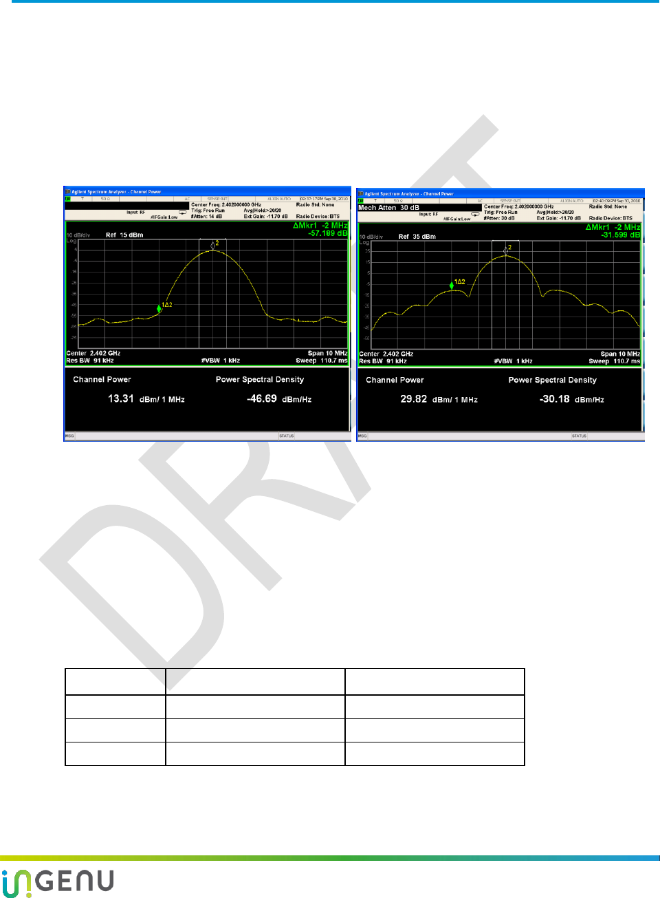
6.1 Transmit Spectral Shape
The spectrum shape of the AP can be described as similar to the Global System for Mobile
Communications (GSM) which uses Gaussian Minimum Shift Keying (GMSK) but with a 1 MHz
signal passband instead of the 200 kHz for GSM. Spectral side lobes are present even when the
transmitter is in the linear range. As the Power Amplifier (PA) goes into compression (starting
around 25 dBm) the main lobe compresses inward while the side lobes increase in amplitude.
Pout 0 dBm Pout 30 dBm
Figure 6. Spectral Shape—Linear and Compressed
6.2 Load VSWR Effects on TX Power Accuracy
The gain of the high power PA (Pout ≥ 16 dBm) is susceptible to load Voltage Standing Wave
Ratio (VSWR). A summary of VSWR effects on TX power accuracy is listed in the following
table. This establishes minimum return loss (VSWR) requirements of ≤ -15 dB. Note that in
normal operation, the closed loop power control will attempt to compensate for some gain
variation.
Table 12. Summary of TX Gain/Power Variation Due to Load VSWR
Return Loss
Gain/Power Variation
Comments
7 dB
± 1.5 dB
Not to specification
15 dB
± 0.7 dB
To specification
20 dB
± 0.35 dB
To specification

16 014-0030-00 Rev. G
7 Hardware Requirements
7.1 Antenna Requirements
For the main antenna the exact model(s) are part of the compliance testing and are required to
be used to avoid EMC non-conformance. In some cases if customers use a different antenna
and it is the same radiation type (monopole, sector, etc.) and is of equal or lower gain, non-
conformance is avoided. The exact requirements are specific to each market. Customers are
encouraged to contact Ingenu application engineering or their local regulatory agency for
details. All main antennas are required to have a return loss in-band of > 15 dB (≤ 1.4:1 VSWR),
per Table 12, for VSWR.
The GPS antenna can be any of the commonly available amplified types on the market. The
optimum gain range is approximately 20 dBic to 50 dBic.
Table 13. Antennas for FCC Configuration
Manufacturer
Part Number
Gain
Comment
Main Antenna
L-com
HG-2409U-PRO
HGV-2409U
9 dBi
8 dBi
N-type connector
N-type connector
GPS Antenna
PCTEL
GPSL1-TMG-SPI-40NCB
40 dBic
N-type connector,
active gain, lightning
protection
NOTE: Depending on the application, Ingenu recommends two options for the main antenna
in the FCC market. The HG-2409U-PRO has 1 dB more gain and slightly more rugged
construction. The HGV-2409U has better return loss and can be mounted upside down.
Table 14. Antennas for ETSI Configuration
Manufacturer
Part Number
Gain
Comment
Main Antenna
L-com
HGV-2402U
0 dBi
N-type connector
GPS Antenna
PCTEL
GPSL1-TMG-SPI-40NCB
40 dBic
N-type connector, active
gain, lightning
protection
Table 15. Antennas for ETSI RFID Configuration
Manufacturer
Part Number
Gain
Comment
Main Antenna
L-com
HG-2417P-090
17 dBi
14 dBi model is also
approved

Access Point Product Specification Hardware Requirements
17 014-0030-00 Rev. G
Manufacturer
Part Number
Gain
Comment
GPS Antenna
PCTEL
GPSL1-TMG-SPI-40NCB
40 dBic
N-type connector,
active gain, lightning
protection
Table 16. Antennas for Japan Configuration
Manufacturer
Part Number
Gain
Comment
Main Antenna
L-Com
HGV-2404U
4 dBi
Limited to 8 dBm
conducted TX
GPS Antenna
PCTEL
GPSL1-TMG-SPI-40NCB
40 dBic
N-type connector, active
gain, lightning
protection
7.2 RF Cable Requirements
It is generally recommended to use very low loss cable such as LMR400. The acceptable loss
ranges are listed in Table 2. Summary of AP Product Specifications. The length that can be
achieved within these ranges depends on the cable chosen.
7.3 Ethernet Speed and Cable Requirements
Unshielded CAT5 (or CAT5E or CAT6) with a length up to 100 meters is permissible. For ETSI
markets the host Ethernet adaptor must be configured for 10 MB full duplex communication,
not 100 MB or auto. Using 100 MB speeds will result in non-compliance to ETSI EMC
regulations, per 489-2: clause 8.7.
7.4 LEDs
The AP has two green LEDs that are visible on its front panel.
Status
This LED indicates RPMA network receive/transmit activity. The AP must be online and
active.
Link
This LED reflects the status of Ethernet activity for the AP.
18 014-0030-00 Rev. G
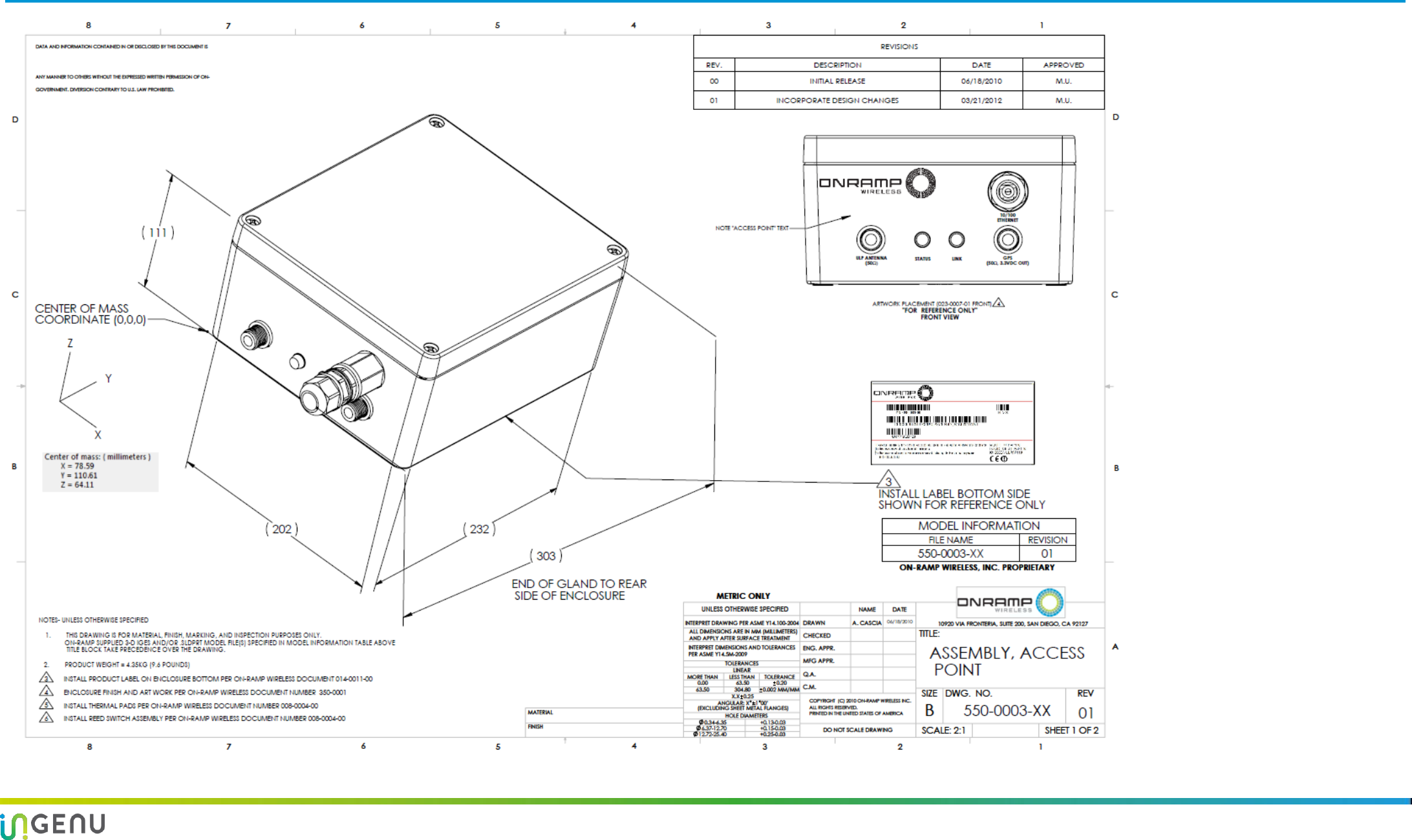
Appendix A Access Point Mechanical Drawing
Figure 7. Access Point Mechanical Drawing

19 014-0030-00 Rev. G
Appendix B Abbreviations and Terms
Abbreviation/Term
Definition
ACPR
Adjacent Channel Power Ratio
AP
Access Point. The RPMA network component geographically deployed over
a territory.
CPU
Central Processing Unit
DSSS
Direct-Sequence Spread Spectrum
EIRP
Effective Isotropic Radiated Power. This is conducted RF power (in dBm)
plus antenna gain (in dBi).
EMC
Electromagnetic Compatibility
ERM
Electromagnetic compatibility and Radio spectrum Matters
ESD
Electrostatic Discharge
ETSI
European Telecommunications Standards Institute
FCC
Federal Communications Commission
GMSK
Gaussian Minimum Shift Keying
GPS
Global Positioning System
GSM
Global System for Mobile Communications
IC
Industry Canada
microNode
A second generation, small form factor, wireless network module
developed by On-Ramp Wireless that works in combination with various
devices and sensors and communicates data to an Access Point.
ODBPSK
Orthogonal Differential BPSK
PA
Power Amplifier
PLL
Phase Locked Loop
PoE
Power over Ethernet
RF
Radio Frequency
RFID
Radio Frequency Identification
RPMA
Random Phase Multiple Access. The On-Ramp Wireless proprietary
wireless communication technology.
RX
Receive/Receiver
SPDT switch
Single Pole Double Throw switch
TX
Transmit/Transmitter
UART
Universal Asynchronous Receiver/Transmitter
VCTCXO
Voltage Controlled Temperature Compensated Crystal Oscillator
VSWR
Voltage Standing Wave Ratio