Inmarsat GSPSCM2 Satellite Radio Module for Inmarsat GMR2+ network User Manual antenna installation
Inmarsat Limited Satellite Radio Module for Inmarsat GMR2+ network antenna installation
Inmarsat >
Contents
- 1. User manual
- 2. User manual supplement
- 3. antenna installation
- 4. Antenna sales sheet
- 5. Antenna installation
antenna installation

20732 Lassen Street, Chatsworth, CA 91311
Phone: (818) 993-3842 Fax: (818) 993-4525
IsatPhone Pro External Antenna Kit
Antenna Model Number: AT1595-90
User Manual
Rev History
Rev Changes
1•First version.
2
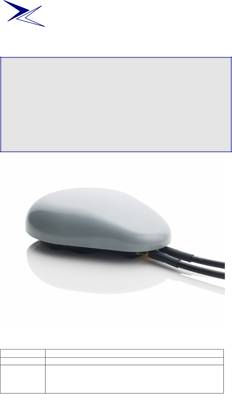
•Changed cover art picture
•Change order of assembly in sec 4.6
•Added sec 4.8 alternative mounting options
•Added sec 4.9 bind long cables together
© 2012 AeroAntenna Technology, Inc. All Rights Reserved.
AeroAntenna Technology, Inc.

AT1595-90 Inmarsat Ground Vehicle Antenna User Manual Rev 2 26 July 2012
1 Introduction
The External Antenna (AT1595-90) is an accessory designed for use with the
IsatPhone Pro on land vehicles. The antenna is sold as part of a kit (see 3
Antenna Kit Contents for detailed contents). When the IsatPhone Pro is
connected to the antenna it is possible for a user to maintain a link to the
satellite while making calls in a moving or stationary land vehicle.
2 Important Safety Information About Exposure to RF Signals
The AT1595-90 is an accessory antenna to the IsatPhone Pro
handset. The IsatPhone Pro is a radio transmitter and receiver;
when turned on, it emits low levels of radio frequency energy. Refer
to the IsatPhone Pro User Manual for more information on potential radio
frequency hazards.
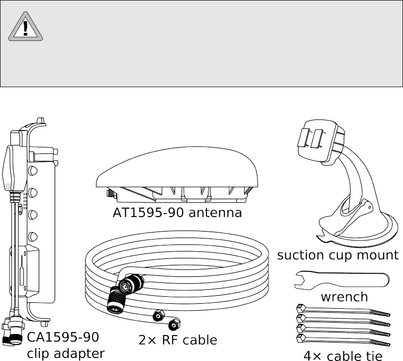
3 Antenna Kit Contents
4 Connecting Your Antenna
4.1 Connect cable to antenna
Connect both cables to the antenna. Use the supplied wrench to ensure a good
connection.
4.2 Place antenna on roof of vehicle
For best results the antenna should be positioned on a flat portion of the roof
of the car where it will have a clear, unobstructed view of the sky in all
directions. Further, for optimal performance the antenna should be placed
away from the edge of the roof and towards the center..
page 2 of 4 © 2011 AeroAntenna Technology, Inc. All Rights Reserved.

4.3 Route cables into vehicle
The cables can now be routed into the vehicle. In many vehicles, the door
seals are sufficiently pliable that they will not damage the cables when the
door is closed.
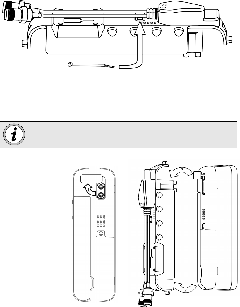
4.4 Affix RF cables to clip with cable tie
For added cable strain relief, use the provided cable tie to firmly secure the
short RF cables on the clip adapter to the clip adapter body.
4.5 Connect 1.5m RF cables to clip adapter
When connecting cables to the clip adapter, care needs to be taken to connect
to the correct ports: match the cable connected to the GPS port on the antenna
to the GPS port on the clip. And likewise, match the cable connected to the
ISAT port on the antenna to the ISAT port on the clip.
If the cables are inadvertently cross-matched, there will be no signal
bars on the phone when it is powered up. Check that the cables
match the antenna and clip ports end-to-end.
4.6 Insert phone into clip
© 2011 AeroAntenna Technology, Inc. All Rights Reserved. page 3 of 4
Insert the phone into
the clip as follows:
1. Open rear connec-
tor access panel
(see figure below)
2. Snap bottom of
handset into clip
adapter
3. Engage connectors
into the handset
and clip adapter to
handset

AT1595-90 Inmarsat Ground Vehicle Antenna User Manual Rev 2 26 July 2012
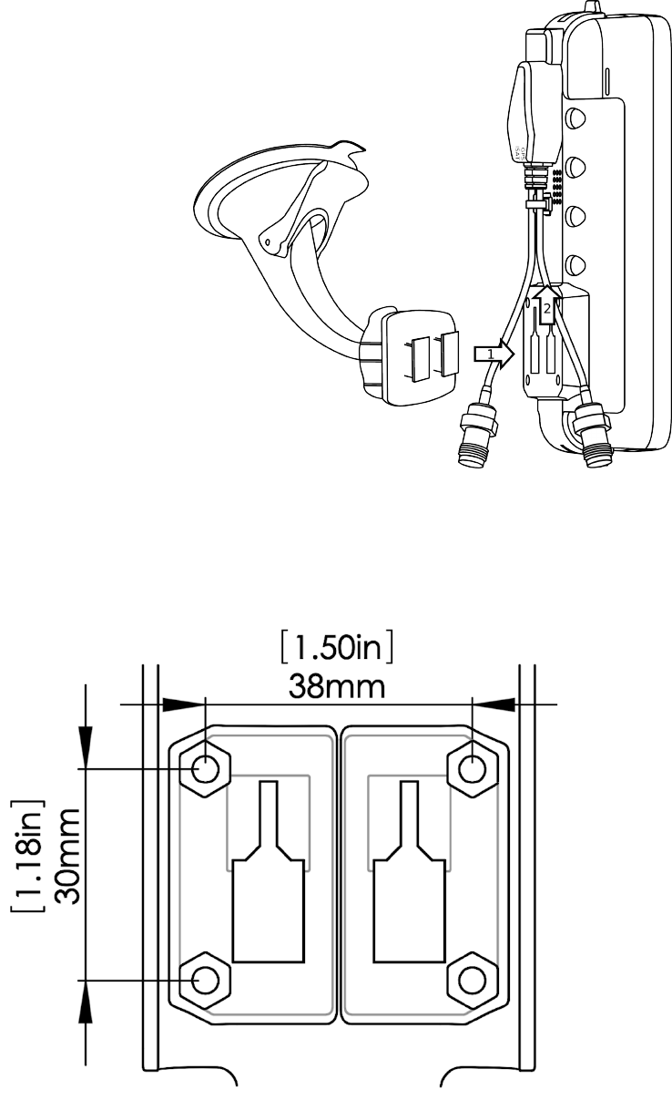
4.7 Suction cup mount
A suction cup mount is
included in the kit for use
with the clip adapter. The
suction cup can be moun-
ted to a window and will
hold the phone securely
for hands-free communi-
cation and while char-
ging via the car charger
(not included).
1. Insert rectangular
tabs on suction cup
mount into clip
adapter
2. Slide tabs up to
lock into place
4.8 Alternative mounting options
The clip adapter also has 4 mounting holes in a standard AMPS pattern
(30mm×38 mm center to center hole pattern) for use with other mounts. As a
precaution, verify printed dimensions before drilling.
page 4 of 4 © 2011 AeroAntenna Technology, Inc. All Rights Reserved.