Inovonics Wireless 3B6ETOEMM wireless transmitter module User Manual FCCRFModuleChapter
Inovonics Wireless Corporation wireless transmitter module FCCRFModuleChapter
Users Manual
1
Inovonics Wireless Confidential: Subject to Non-Disclosure Agreement
RF Module
1.1 Introduction
EchoStream RF modules allow the assimilation of any user-specific application into an
EchoStream system. The RF modules can be integrated with your existing product to
provide you with complete EchoStream functionality.
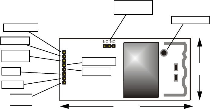
1.1.1 E*1941 One-Way RF Module
The E*1941 is a universal one way RF module with a two alarm input pins, allowing for
the use of dual inputs. Input one is the primary alarm, bit 0; input two is the secondary
alarm bit 1.
Figure 1-1 E*1941 Dual-Input Universal Transmitter Components
N/O - N/C selection pins Place a jumper to select whether the inputs are normally open
or normally closed.
Serial output Connects a serial device to output RF messages from the ES1941.
Serial input Connects a serial device to input RF messages to the ES1941.
Serial Output
Serial Input
Primary
Alarm
Secondary
Alarm Tamper Input
Reset Input
Power
Ground
N/O- N/C
Selection Pins
1.3”
2.525”
Mounting Hole

Introduction
2Inovonics Wireless Confidential: Subject to Non-Disclosure Agreement
Secondary alarm Connects a secondary end-device to provide RF alarm data for any
user-specific application.
Tamper input Connects a tamper input to send a message when user-specific end-device
is tampered with.
Reset input Connects a reset input, to reset the RF module after a frequency band
selection change or N/O - N/C selection change.
Power The E*1941 has an on-board voltage regulator. Connect power cabling to an
external power supply of 2.5 to 5.5 volts. Voltage must be sustained at 2.5 volts or above
and supply 50 milliamps during the transmit cycle.
Ground Connects a ground.
Primary alarm Connects a primary end-device to provide RF alarm data for any user-
specific application.
Mounting Hole Used to mount the RF module to the user-specific product. The
mounting hole should only be used with a nylon standoff, never metal.
Connection Output Jumper N/O Output Jumper N/C
Primary Alarm Open Alarm Clear Alarm
Ground Alarm Alarm Clear
Secondary Alarm Open Alarm Clear Alarm
Ground Alarm Alarm Clear
Tamper Open Alarm Alarm
Ground Alarm Clear Alarm Clear
Reset Open for normal operation; connect to the ground and release for a board
reset.
RF Module
3
Inovonics Wireless Confidential: Subject to Non-Disclosure Agreement
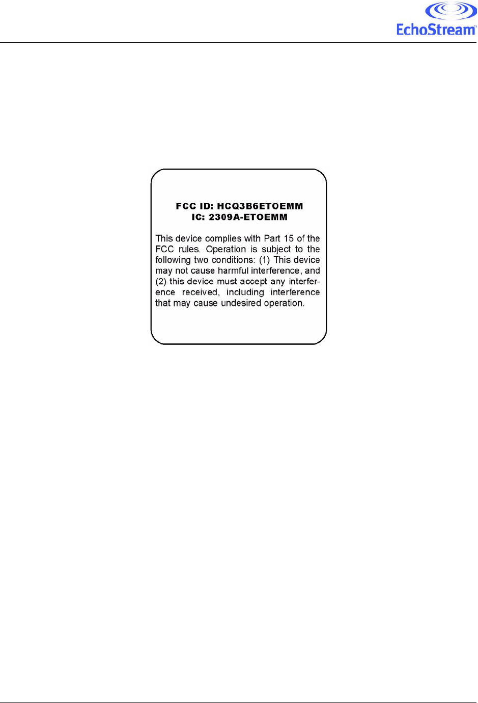
1.1.2 FCC Label Requirements
Inovonics Wireless has received Federal Communications Commission (FCC) and
Industry Canada (IC) approval to market RF modules. The application integrator is
responsible for properly labeling the product containing the RF module. Labels must be
placed on the outside of the product, and must include the FCC registration number, the
IC registration number and the FCC statement as shown in the sample label below: