Inseego NVWE362 Cellular/ PCS GSM/ EDGE/ WCDMA/ CDMA and 700 MHz LTE Module User Manual Aegis 200B4A eng indb
Novatel Wireless Inc Cellular/ PCS GSM/ EDGE/ WCDMA/ CDMA and 700 MHz LTE Module Aegis 200B4A eng indb
Inseego >
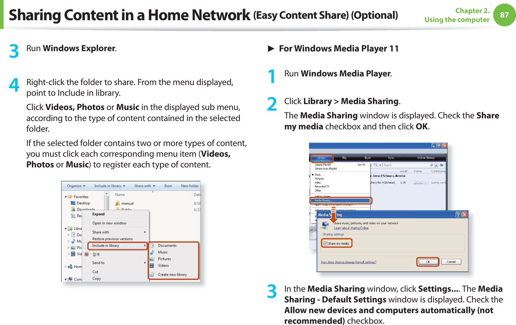
Contents
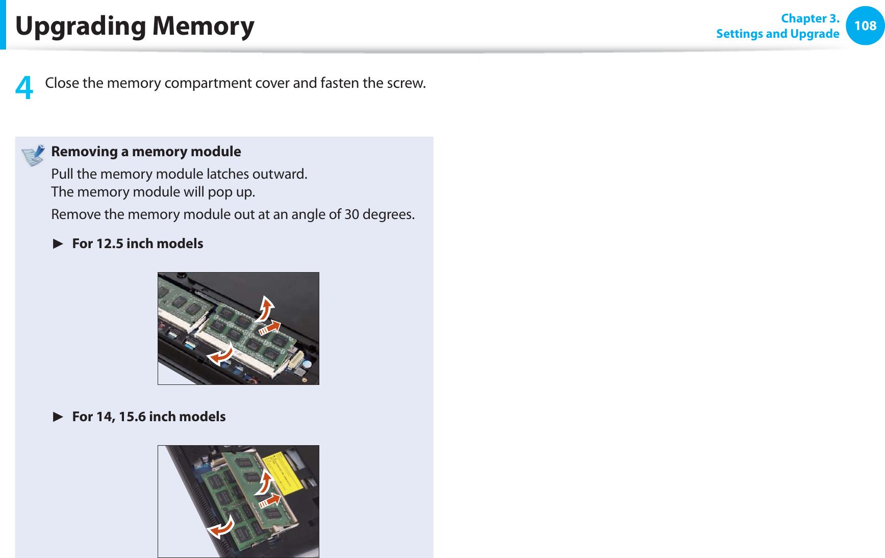
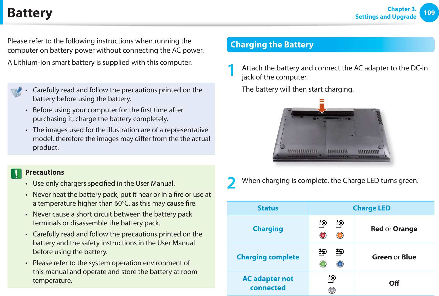
Host user manual 2 of 3
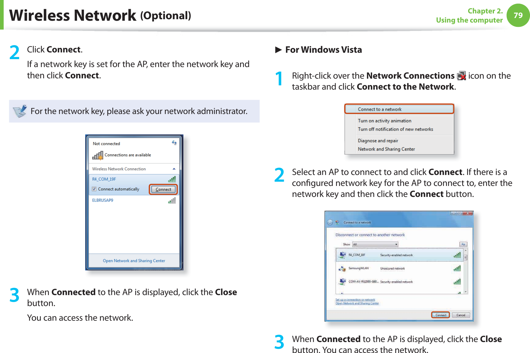
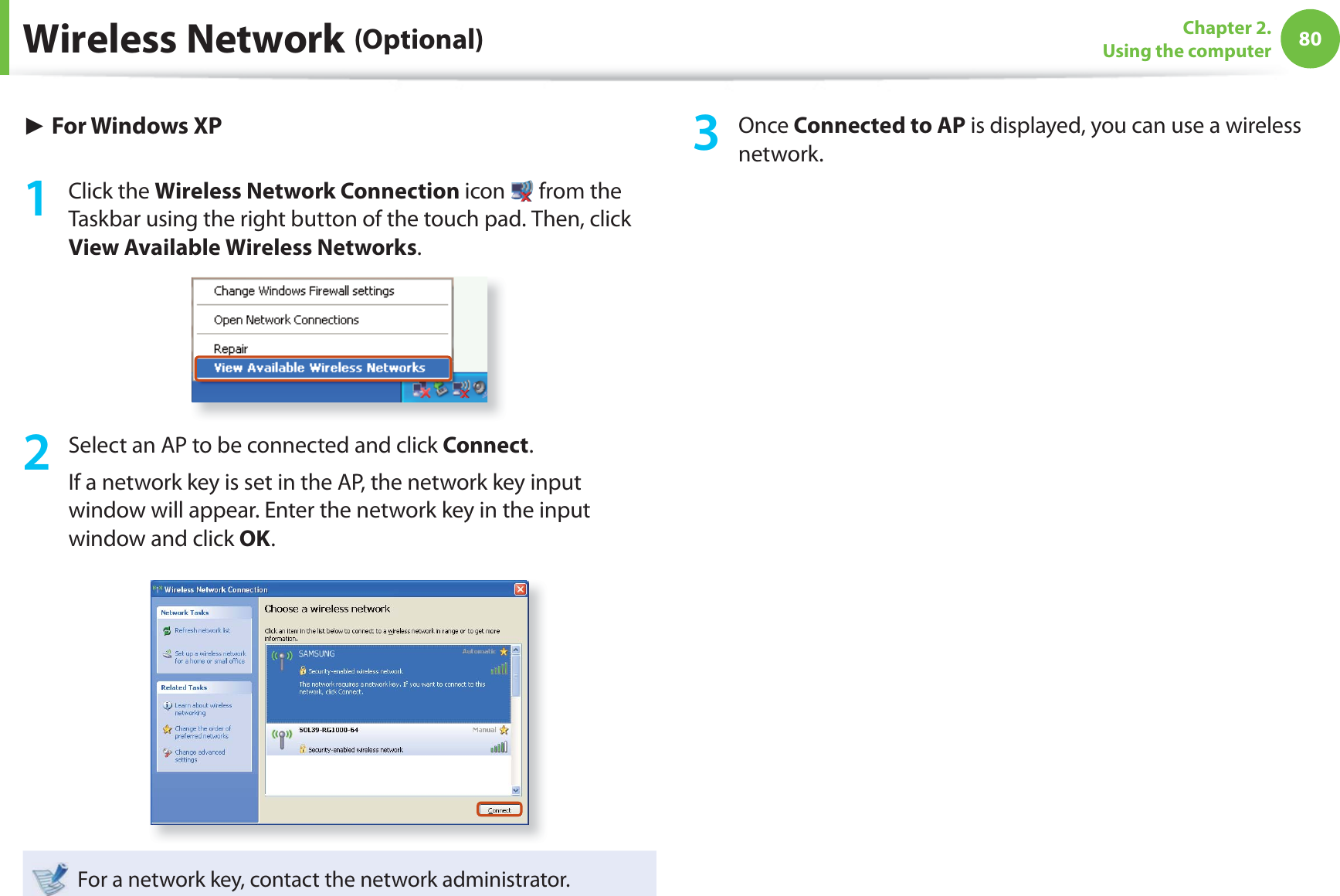
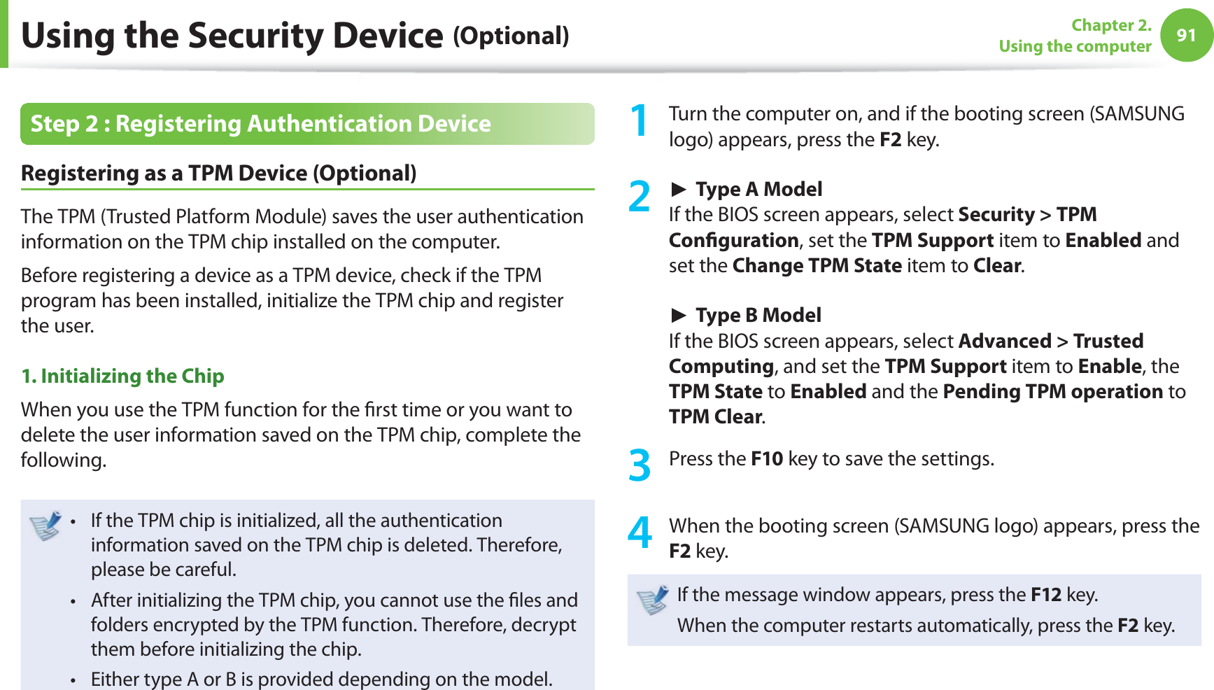
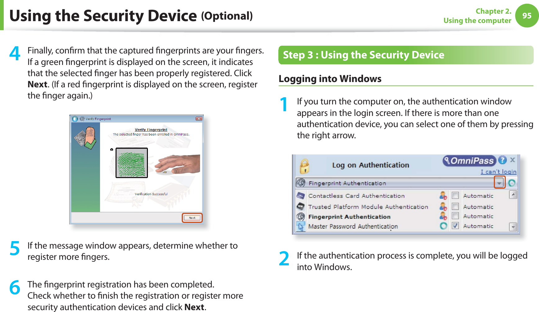
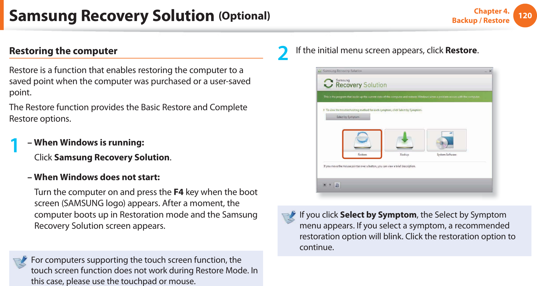
![81Chapter 2. Using the computerWireless Network (Optional)Connecting to a wireless network through Wi-Fi Manager (Optional) These descriptions are for Windows 7 and for supported models only. You can access a wireless network using Wi-Fi Manager.1 Press the + key combination. Then the Wi-Fi Manager window appears. 2 Select Wi-Fi and check if it is set to ON.If this option is set to ON, the Wi-Fi function will run.You can set this to ON or OFF.AP ListWlnNormal Wireless Network StatusIf the wireless LAN icon is displayed in the system tray of the Taskbar, it indicates that the computer is connected to the Internet properly (see below).[Windows 7] [Windows Vista] [Windows XP]](https://usermanual.wiki/Inseego/NVWE362.Host-user-manual-2-of-3/User-Guide-1581670-Page-4.png)
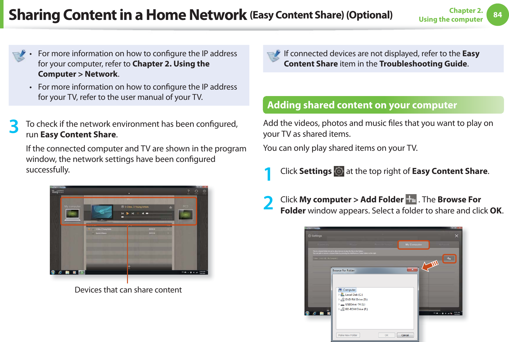
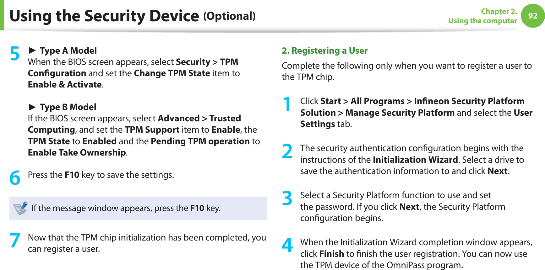
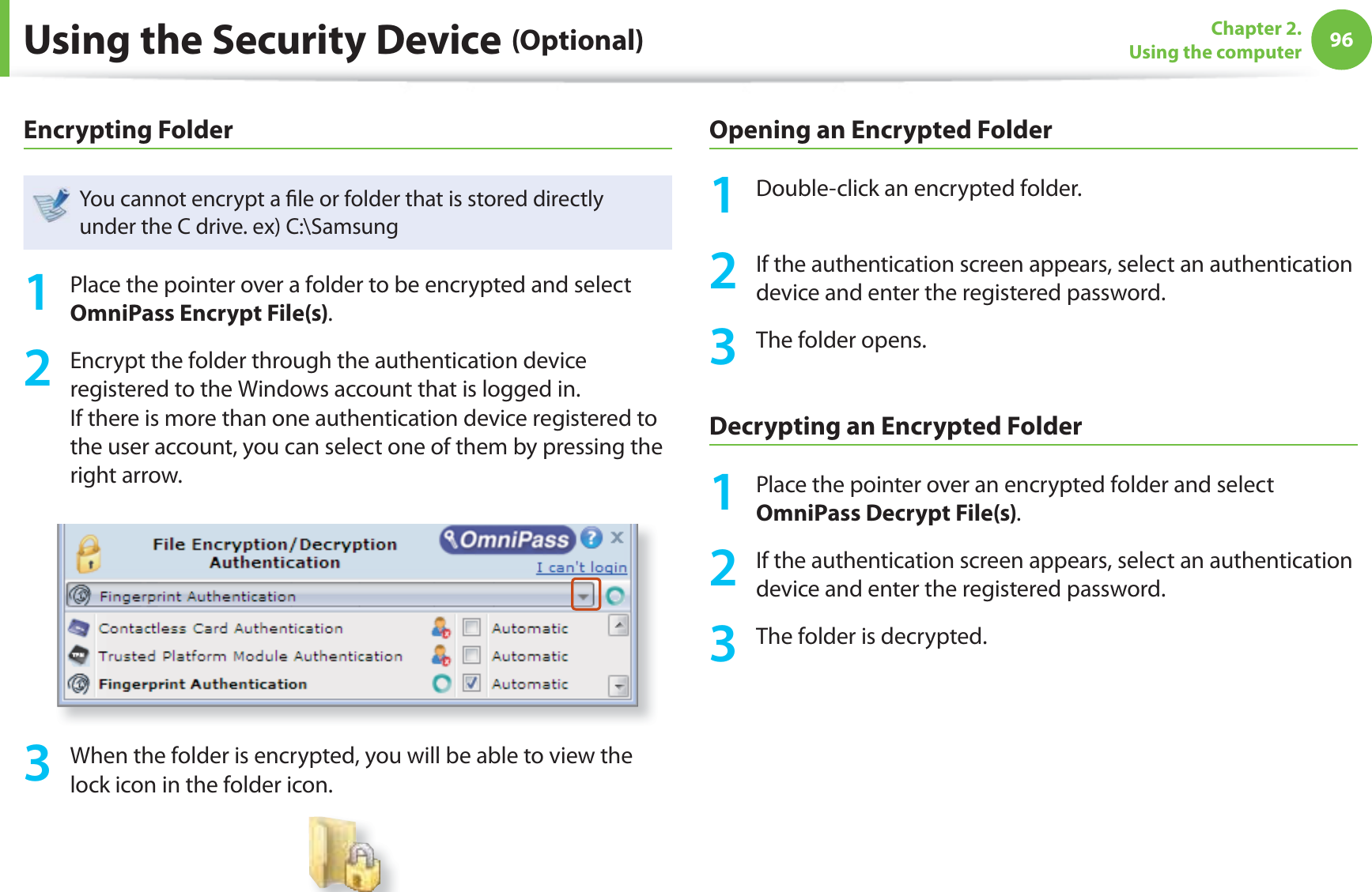
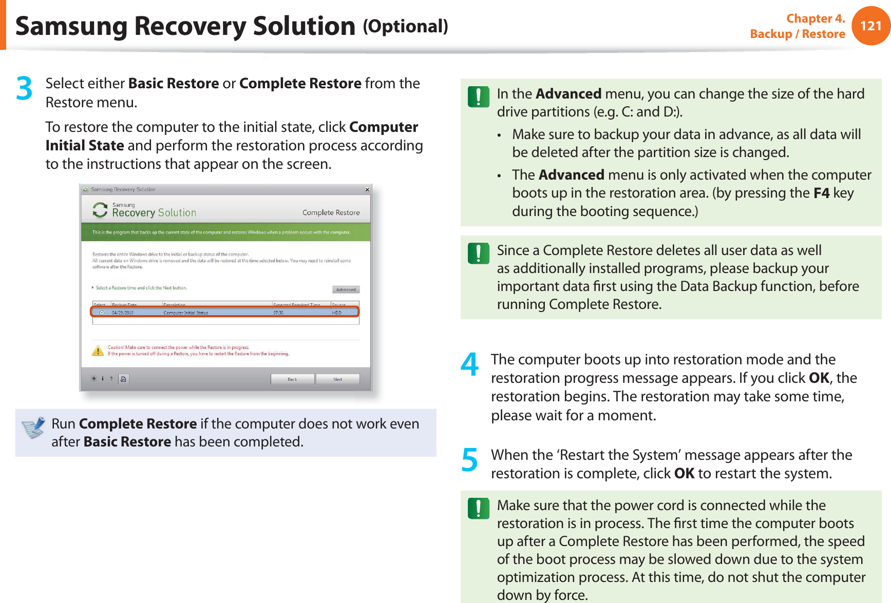
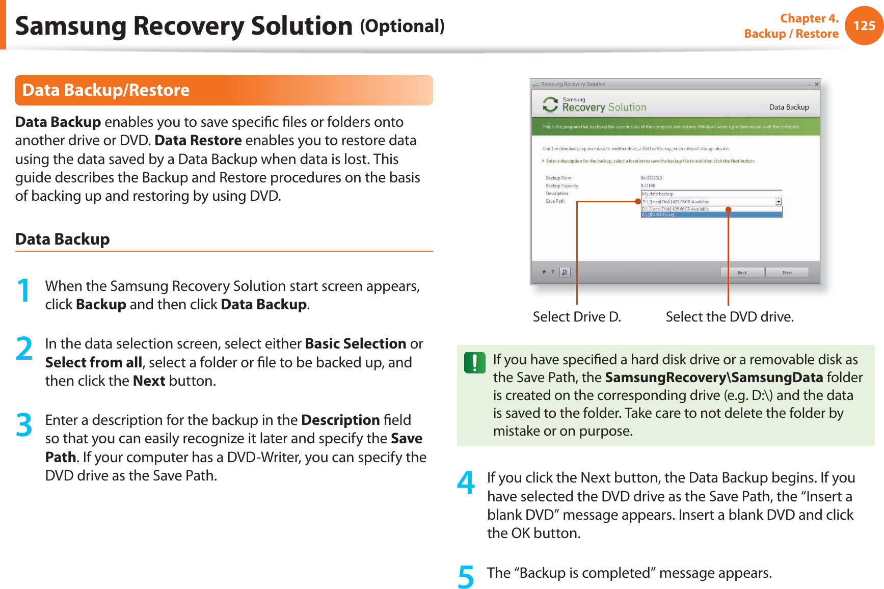
![82Chapter 2. Using the computerWireless Network (Optional)Abnormal Wireless Network StatusWhen the wireless LAN is not connectedIf the wireless LAN icon is displayed with an “X” in the system tray of the Taskbar, it indicates that the wireless LAN device is turned off or that there are no available APs. Or the wireless LAN is disconnected.[Windows 7] [Windows Vista] [Windows XP]If the wireless LAN is turned off , press the + key combination to turn it on.When you are not connected to the InternetThis is indicated by the wireless LAN icon in the system tray of the Taskbar. In this case, you have to check the IP address settings.Please contact your network administrator and reconfi gure the IP address.[Windows 7] [Vista] [Windows XP]When APs are found but your computer is not connected to the InternetThis is the case when an AP with a weak signal has been set to a high priority. Connect to an AP with a strong signal by clicking it.An AP with a strong signal strengthThe currently connected AP. The signal strength is low.Click[Windows 7][Windows XP]An AP with a strong signal strengthThe currently connected AP. The signal strength is low.Click](https://usermanual.wiki/Inseego/NVWE362.Host-user-manual-2-of-3/User-Guide-1581670-Page-5.png)
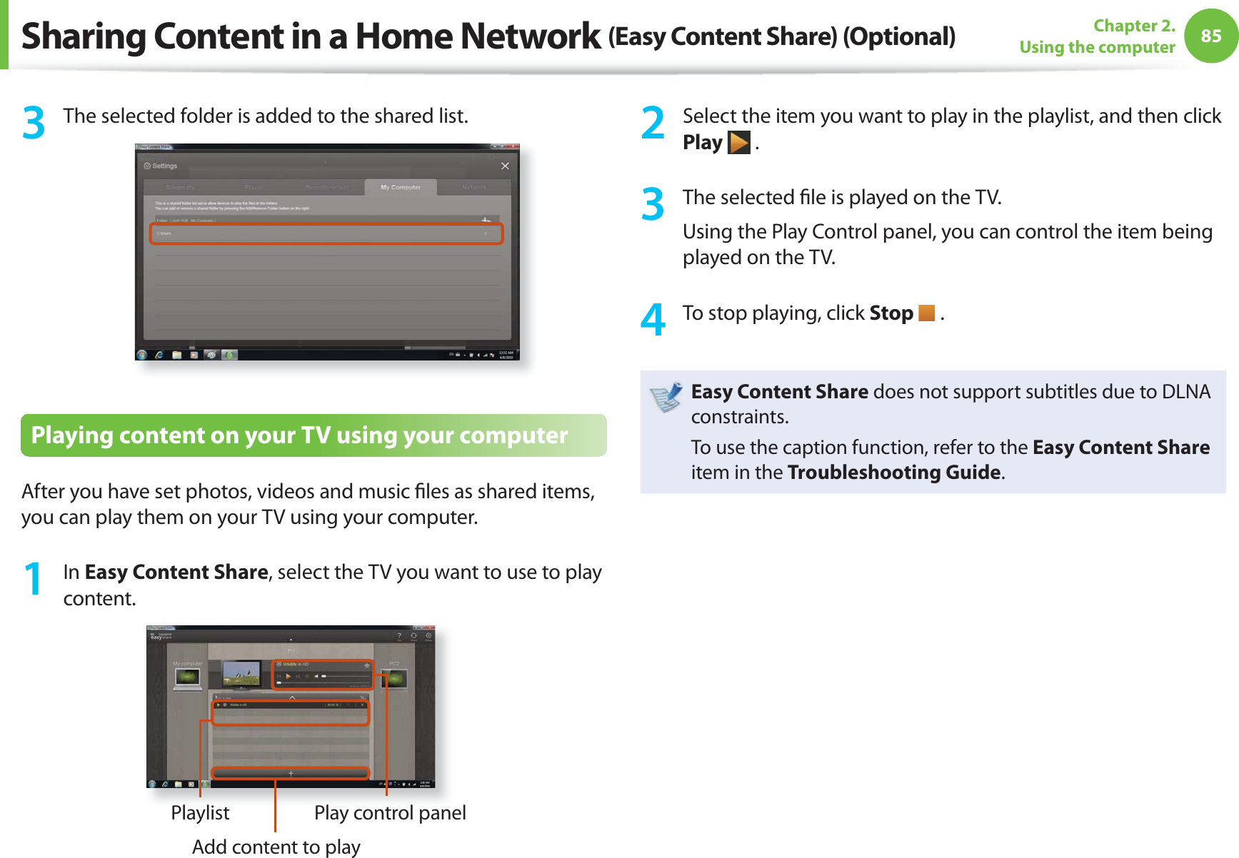
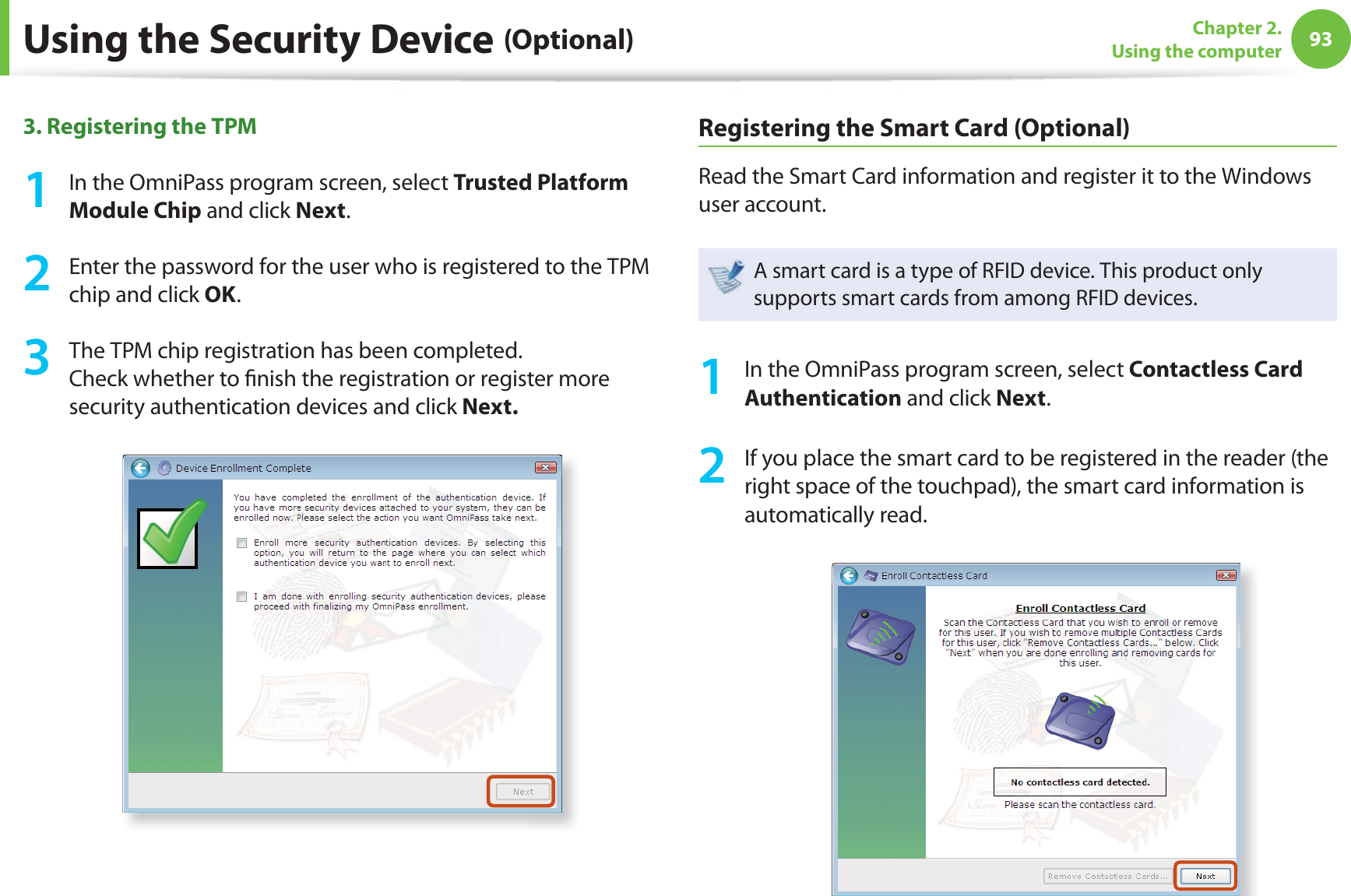
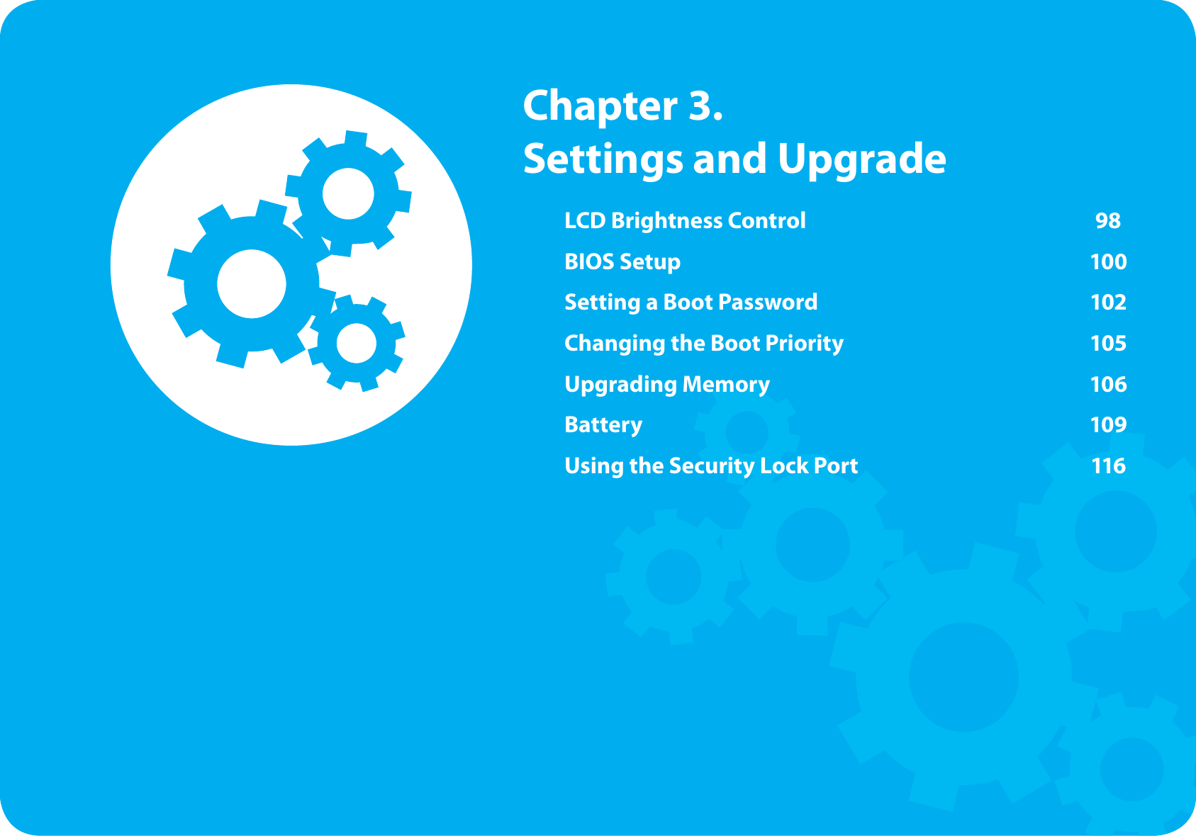
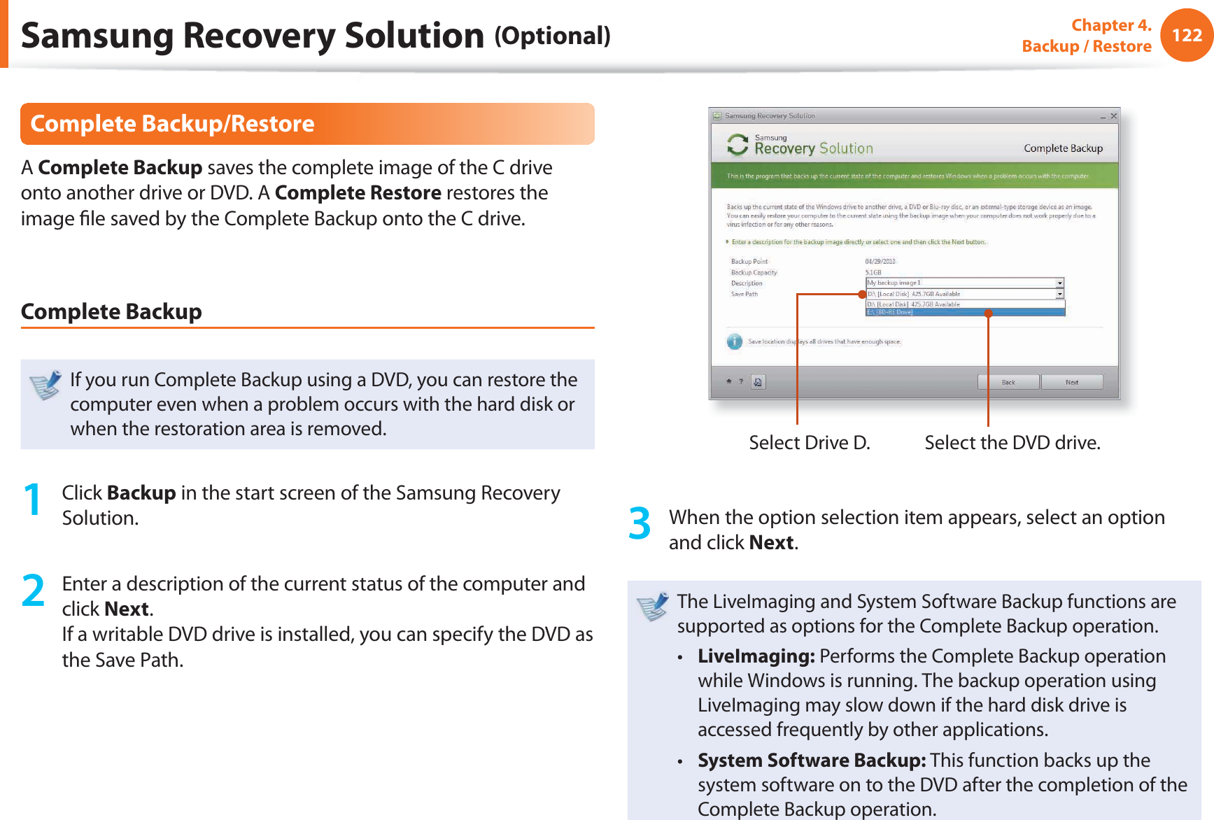
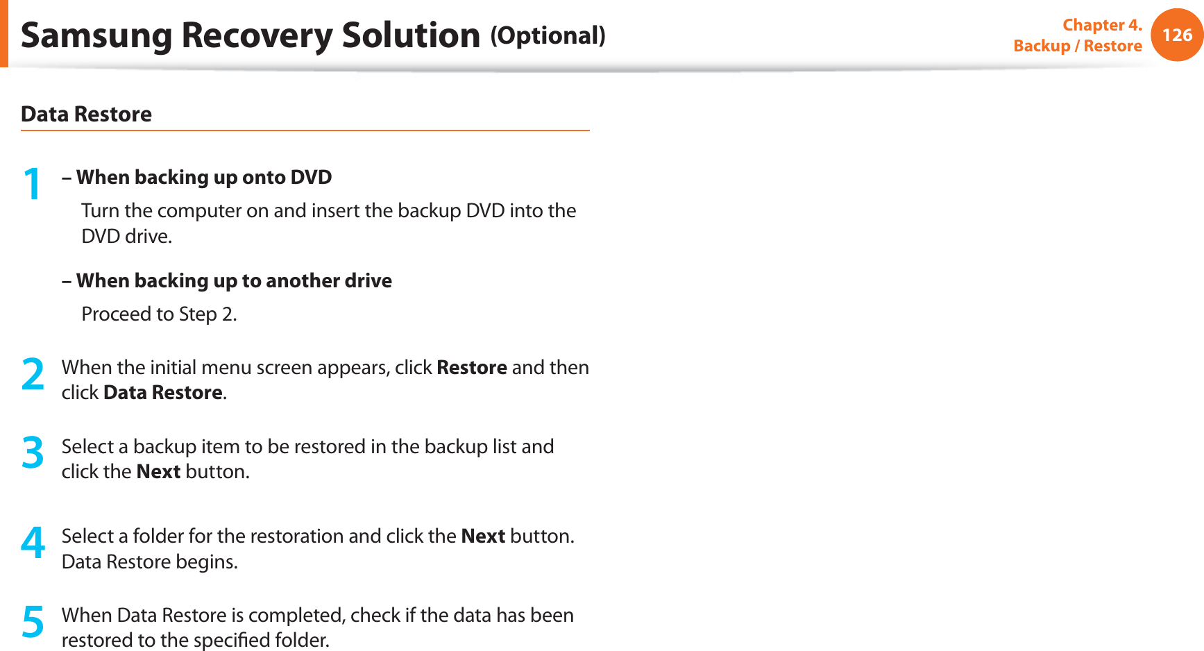
![83Chapter 2. Using the computerSharing Content in a Home Network (Easy Content Share) (Optional)Easy Content Share is a DLNA application that allows you to play photos, videos and music fi les on your TV.These descriptions are for Windows 7 and for supported t models only. The Digital Living Network Alliance (DLNA) aligns industry t leaders in the CE, mobile, and PC industries through digital interoperability, and DLNA-certifi ed devices allow users to play videos, photos and music fi les stored on a computer on a TV. To play content using DLNA technology, both your t computer and TV must be DLNA certifi ed.For information on whether a product supports DLNA, refer to the respective user manuals.To play videos, photos and music fi les stored on a computer, confi gure the settings in the order as shown below.1. Confi guring the network settings for your computer and TV2. Adding shared content on your computer3. Playing content on your TV using your computerConfi guring the network settings for your computer and TVTo share content, all shared devices must be connected to the same access point.Confi gure the network settings by following the steps below.1 Connect your computer and TV to an access point through a wired or wireless LAN connection, as shown in the fi gure below.[Network connection diagram]2 Confi gure the IP address settings for your computer and TV.You must check the Obtain an IP address automatically (DHCP) checkbox.](https://usermanual.wiki/Inseego/NVWE362.Host-user-manual-2-of-3/User-Guide-1581670-Page-6.png)
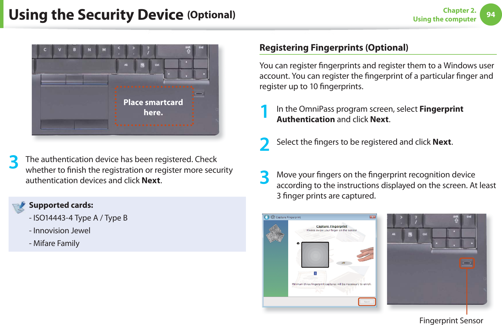
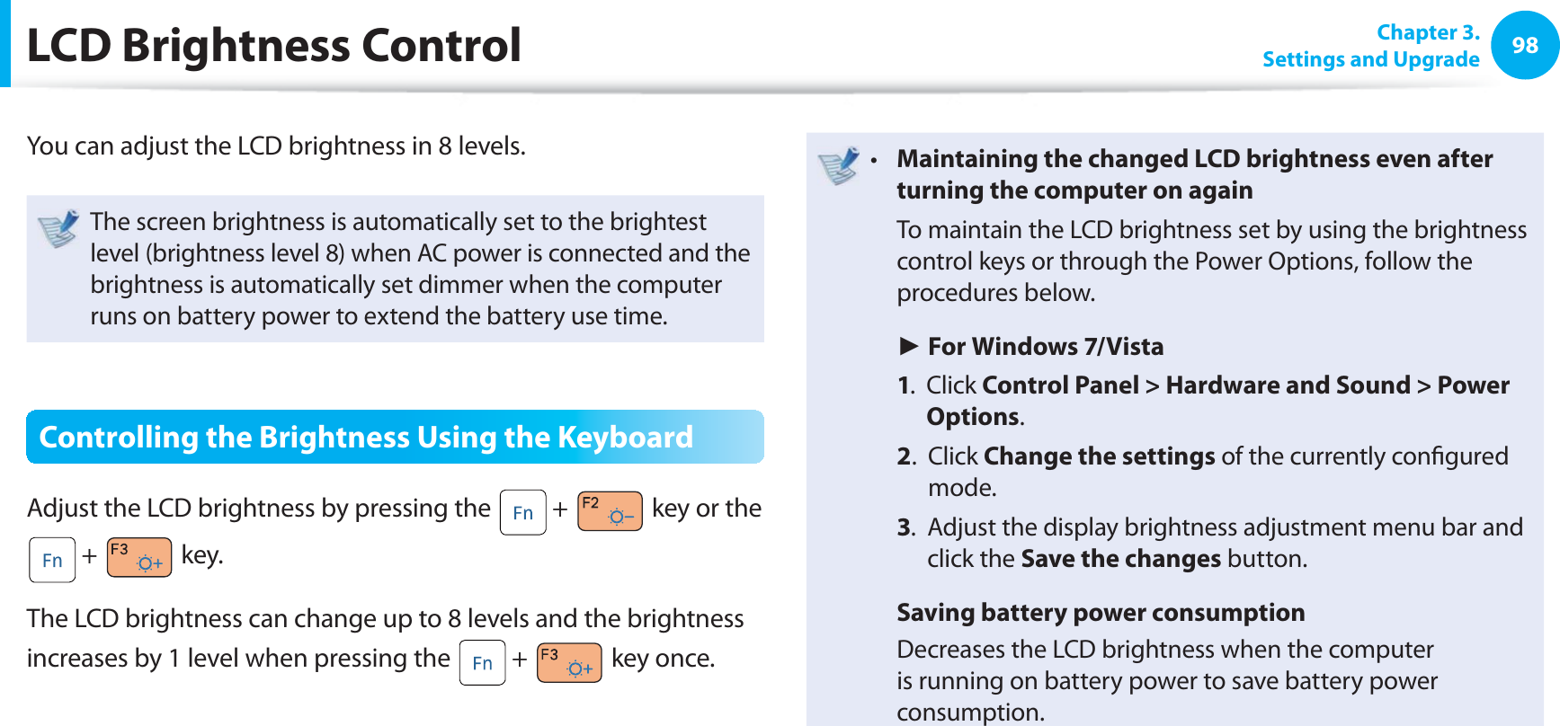
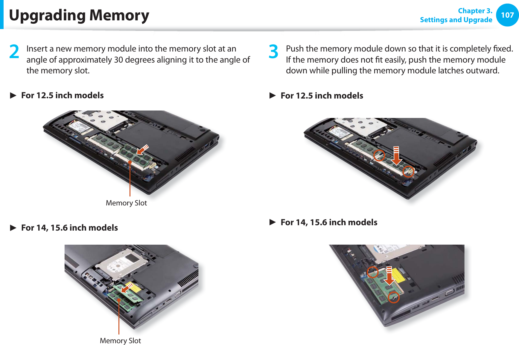
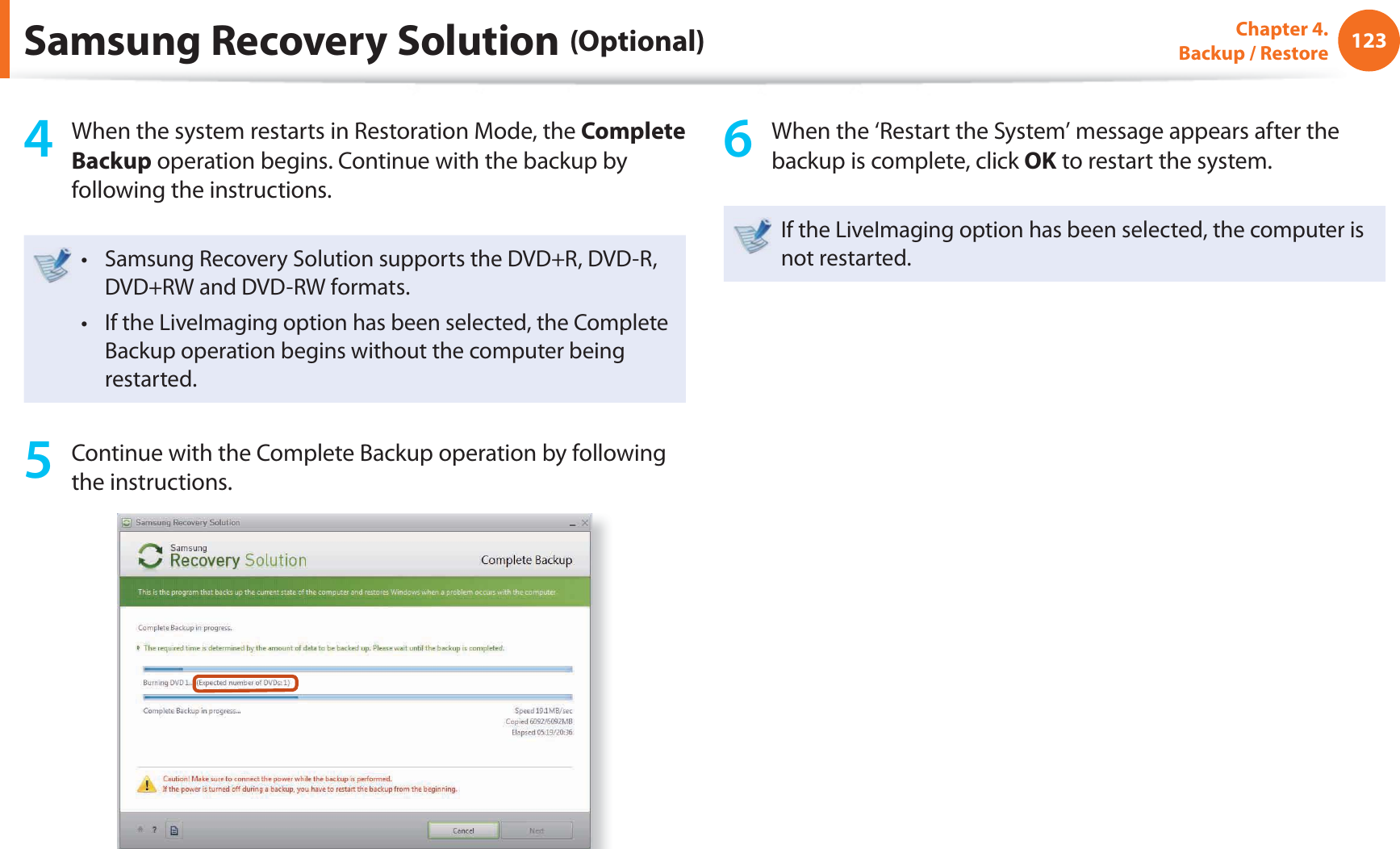
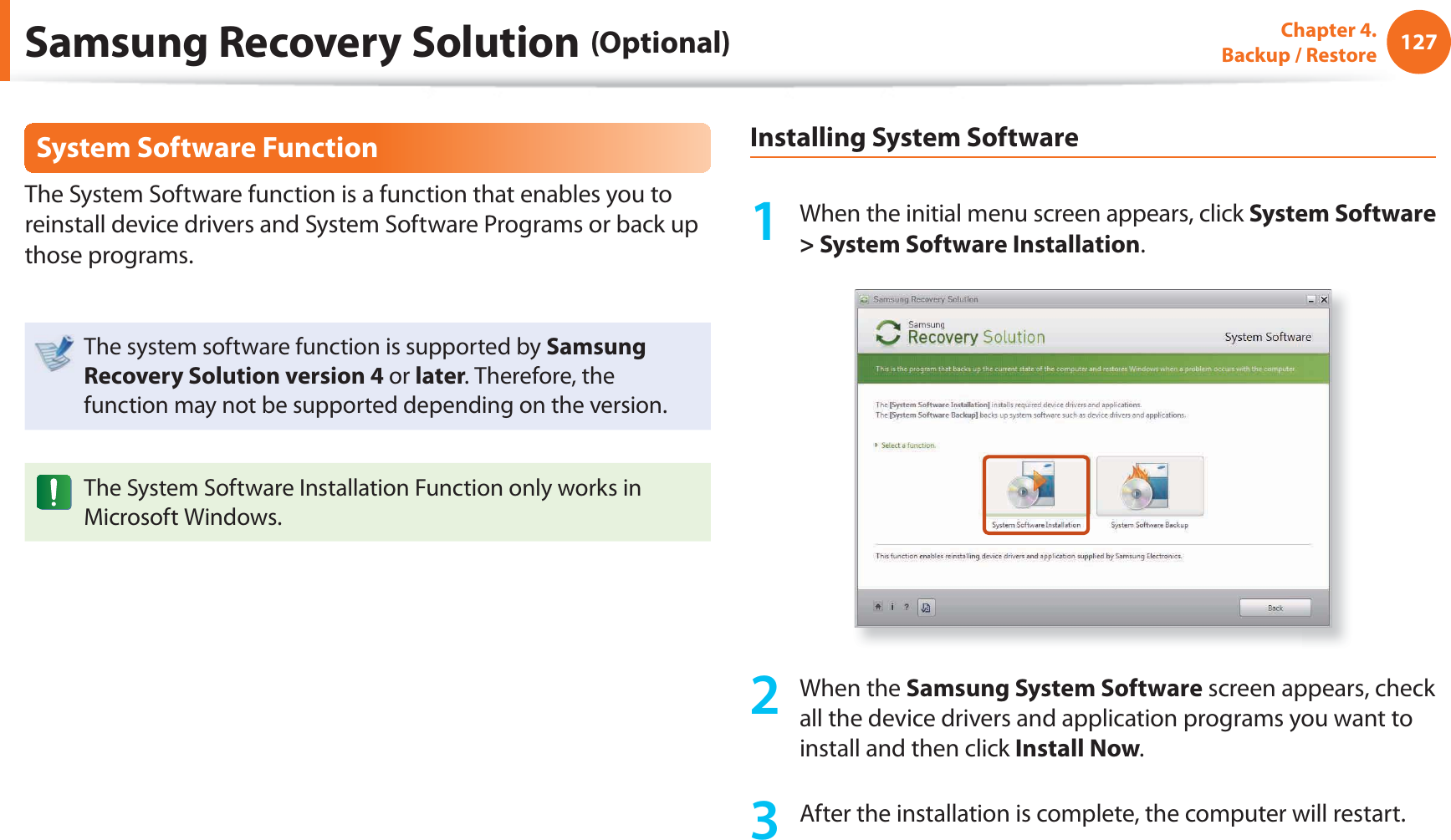
![105 Chapter 3.Settings and UpgradeChanging the Boot PriorityBy default, the highest boot priority device is set to the CD-ROM/DVD drive. As an example, the procedures to change the highest boot priority device to the hard disk drive are described below.The screen images and terms may diff er from actual product depending on the computer model and driver version.1 Select the Boot menu in the BIOS Setup.2 Press <Enter> on the Boot Device Priority item.0WO.QEM =1HH?6QWEJ2CF/QWUG ='PCDNGF?+PVGTPCN.#0 ='PCDNGF?2:'1241/ =&KUCDNGF?5OCTV$CVVGT[%CNKDTCVKQP3 Press the down key (↓) to move to the SATA HDD item and press the F6 key to move up to the top item.Boot Device Priority[Set Boot Priority]1. SATA CD : XXXXXXXXXXXX2. SATA HDD : XXXXXXXXXXXX3. USB CD : N/A4. USB KEY : N/A5. USB FDD : N/A6. USB HDD : N/A7. NETWORK : N/A4 Press the F10 key to save the settings and exit Setup. The highest boot priority device is now set to the Hard Drive.](https://usermanual.wiki/Inseego/NVWE362.Host-user-manual-2-of-3/User-Guide-1581670-Page-28.png)
![145Chapter 5. AppendixEuropean Radio Approval Information (for products fi tted with EU-approved radio devices)This Product is a Notebook computer; low power, Radio LAN type devices (radio frequency (RF) wireless communication devices), operating in the 2.4GHz/5GHz band, may be present (embedded) in your notebook system which is intended for home or offi ce use. This section is only applicable if these devices are present. Refer to the system label to verify the presence of wireless devices.Wireless devices that may be in your system are only qualifi ed for use in the European Union or associated areas if a CE mark with a Notifi ed Body Registration Number and the Alert Symbol is on the system label.The power output of the wireless device or devices that may be embedded in you notebook is well below the RF exposure limits as set by the European Commission through the R&TTE directive.The low band 5.15 - 5.35 GHz is for indoor use only.See 802.11b and 802.11g restrictions for specifi c countries or regions within countries under the heading “European Economic Area Restrictions” below.EU R&TTE Compliance StatementsČesky[Czech]Samsung tímto prohlašuje, že tento Notebook PC je ve shodě se základními požadavky a dalšími příslušnými ustanoveními směrnice 1999/5/ES.Dansk[Danish]Undertegnede Samsung erklærer herved, at følgende udstyr Notebook PC overholder de væsentlige krav og øvrige relevante krav i direktiv 1999/5/EF.Deutsch[German]Hiermit erklärt Samsung, dass sich das Gerät Notebook PC in Übereinstimmung mit den grundlegenden Anforderungen und den übrigen einschlägigen Bestimmungen der Richtlinie 1999/5/EG befi ndet.Eesti[Estonian]Käesolevaga kinnitab Samsung seadme Notebook PC vastavust direktiivi 1999/5/EÜ põhinõuetele ja nimetatud direktiivist tulenevatele teistele asjakohastele sätetele.EnglishHereby, Samsung, declares that this Notebook PC is in compliance with the essential requirements and other relevant provisions of Directive 1999/5/EC.Español[Spanish]Por medio de la presente Samsung declara que el Notebook PC cumple con los requisitos esenciales y cualesquiera otras disposiciones aplicables o exigibles de la Directiva 1999/5/CE.Regulatory Compliance Statements](https://usermanual.wiki/Inseego/NVWE362.Host-user-manual-2-of-3/User-Guide-1581670-Page-68.png)
![146Chapter 5. AppendixΕλληνική[Greek]ΜΕ ΤΗΝ ΠΑΡΟΥΣΑ Samsung ΔΗΛΩΝΕΙ ΟΤΙ Notebook PC ΣΥΜΜΟΡΦΩΝΕΤΑΙ ΠΡΟΣ ΤΙΣ ΟΥΣΙΩΔΕΙΣ ΑΠΑΙΤΗΣΕΙΣ ΚΑΙ ΤΙΣ ΛΟΙΠΕΣ ΣΧΕΤΙΚΕΣ ΔΙΑΤΑΞΕΙΣ ΤΗΣ ΟΔΗΓΙΑΣ 1999/5/ΕΚ.Français[French]Par la présente Samsung déclare que l’appareil Notebook PC est conforme aux exigences essentielles et aux autres dispositions pertinentes de la directive 1999/5/CE.Italiano[Italian]Con la presente Samsung dichiara che questo Notebook PC è conforme ai requisiti essenziali ed alle altre disposizioni pertinenti stabilite dalla direttiva 1999/5/CE.Latviski[Latvian]Ar šo Samsung deklarē, ka Notebook PC atbilst Direktīvas 1999/5/EK būtiskajām prasībām un citiem ar to saistītajiem noteikumiem.Lietuvių[Lithuanian]Šiuo Samsung deklaruoja, kad šis Notebook PC atitinka esminius reikalavimus ir kitas 1999/5/EB Direktyvos nuostatas.Nederlands[Dutch]Hierbij verklaart Samsung dat het toestel Notebook PC in overeenstemming is met de essentiële eisen en de andere relevante bepalingen van richtlijn 1999/5/EG.Malti[Maltese]Hawnhekk, Samsung, jiddikjara li dan Notebook PC jikkonforma mal-ħtiāijiet essenzjali u ma provvedimenti oħrajn relevanti li hemm fi d-Dirrettiva 1999/5/EC.Magyar[Hungarian]Alulírott, Samsung nyilatkozom, hogy a Notebook PC megfelel a vonatkozó alapvetõ követelményeknek és az 1999/5/EC irányelv egyéb elõírásainak.Polski[Polish]Niniejszym Samsung oświadcza, Ŝe Notebook PC jest zgodny z zasadniczymi wymogami oraz pozostałymi stosownymi postanowieniami Dyrektywy 1999/5/EC.Português[Portuguese]Samsung declara que este Notebook PC está conforme com os requisitos essenciais e outras disposições da Directiva 1999/5/CE.Slovensko[Slovenian]Samsung izjavlja, da je ta Notebook PC v skladu z bistvenimi zahtevami in ostalimi relevantnimi določili direktive 1999/5/ES.Slovensky[Slovak]Samsung týmto vyhlasuje, že Notebook PC spĺňa základné požiadavky a všetky príslušné ustanovenia Smernice 1999/5/ES.Suomi[Finnish]Samsung vakuuttaa täten että Notebook PC tyyppinen laite on direktiivin 1999/5/EY oleellisten vaatimusten ja sitä koskevien direktiivin muiden ehtojen mukainen.Svenska[Swedish]Härmed intygar Samsung att denna Notebook PC står I överensstämmelse med de väsentliga egenskapskrav och övriga relevanta bestämmelser som framgår av direktiv 1999/5/EG.Regulatory Compliance Statements](https://usermanual.wiki/Inseego/NVWE362.Host-user-manual-2-of-3/User-Guide-1581670-Page-69.png)
![147Chapter 5. AppendixÍslenska[Icelandic]Hér með lýsir Samsung yfi r því að Notebook PC er í samræmi við grunnkröfur og aðrar kröfur, sem gerðar eru í tilskipun 1999/5/EC.Norsk[Norwegian]Samsung erklærer herved at utstyret Notebook PC er i samsvar med de grunnleggende krav og øvrige relevante krav i direktiv 1999/5/EF.Türkiye[Türkçe]Bu belge ile, Samsung bu Notebook PC’nin 1999/5/EC Yönetmeliğinin temel gerekliliklerine ve ilgili hükümlerine uygun olduğunu beyan eder.To view the EU Declaration of Conformity for this product (in English only), go to: http://www.samsung.com/uk/support/download/supportDownMain.do then search the model number of the product.If the Declaration of Conformity for the model you are interested in is not available on our web-site, please contact your distributor.European Economic Area RestrictionsLocal Restriction of 802.11b/802.11g Radio Usage[Note to integrator: The following statements on local restrictions must be published in all end-user documentation provided with the system or product incorporating the wireless product.]Due to the fact that the frequencies used by 802.11b/802.11g wireless LAN devices may not yet be harmonized in all countries, 802.11b/802.11g products are designed for use only in specifi c countries or regions, and are not allowed to be operated in countries or regions other than those of designated use.As a user of these products, you are responsible for ensuring that the products are used only in the countries or regions for which they were intended and for verifying that they are confi gured with the correct selection of frequency and channel for the country or region of use. Any deviation from permissible settings and restrictions in the country or region of use could be an infringement of local law and may be punished as such.Regulatory Compliance Statements](https://usermanual.wiki/Inseego/NVWE362.Host-user-manual-2-of-3/User-Guide-1581670-Page-70.png)