Inseego NVWE362 Cellular/ PCS GSM/ EDGE/ WCDMA/ CDMA and 700 MHz LTE Module User Manual Aegis 200B4A eng indb
Novatel Wireless Inc Cellular/ PCS GSM/ EDGE/ WCDMA/ CDMA and 700 MHz LTE Module Aegis 200B4A eng indb
Inseego >
Contents
Host user manual 2 of 3
78
Chapter 2.
Using the computer
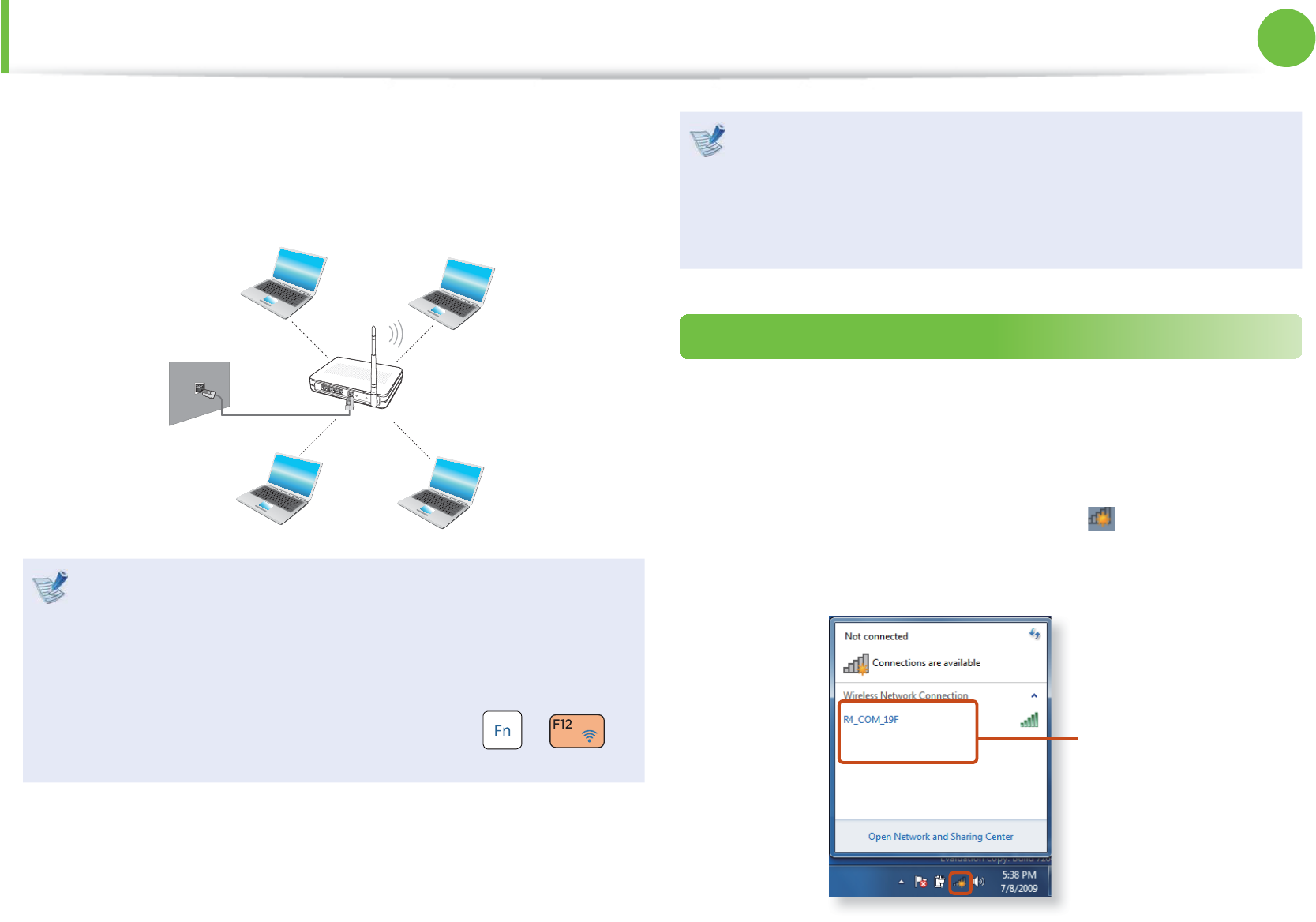
A wireless network (Wireless LAN) environment is a network
environment that enables communicating between multiple
computers at home or a small-size offi ce through wireless LAN
devices.
The descriptions below are for computer models with t
a Wireless LAN card or device. A Wireless LAN device is
optional.
The pictures in this manual may diff er from the actual
product depending on your wireless LAN device model.
If the wireless LAN is turned off , press the t +
key combination to turn it on.
What is an Access Point ( AP)?
An AP is a network device that bridges wired and wireless
LANs, and corresponds to a wireless hub in a wired network.
Connect the computer with the wireless LAN function to the
AP to use to the network connection.
Connecting to a Wireless LAN
If there is an AP, you can connect to the Internet via the AP using
the Wireless LAN connection method provided by Windows.
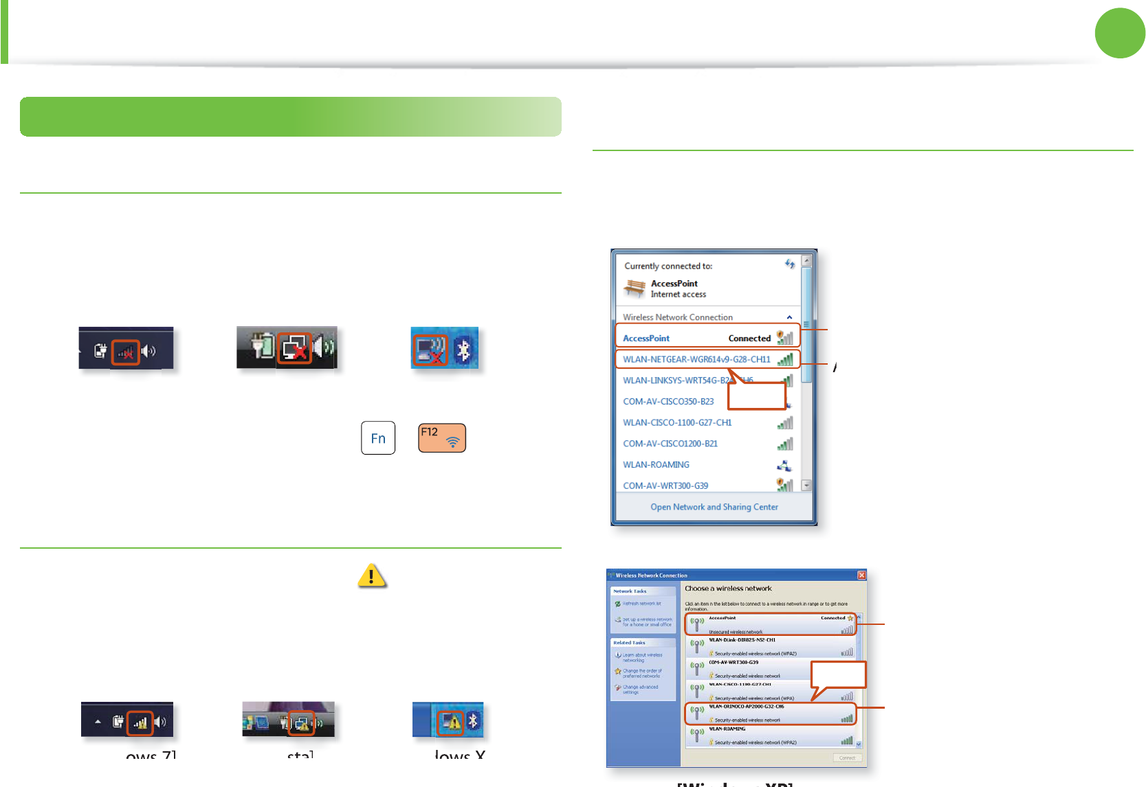
► For Windows 7
1 If you click the Network Connections icon in the system
tray, a list of available APs appears. If you select an AP to
connect to, the Connect button appears.
AP List
Wireless Network (Optional)
79
Chapter 2.
Using the computer
Wireless Network (Optional)
2 Click Connect.
If a network key is set for the AP, enter the network key and
then click Connect.
For the network key, please ask your network administrator.
3 When Connected to the AP is displayed, click the Close
button.
You can access the network.
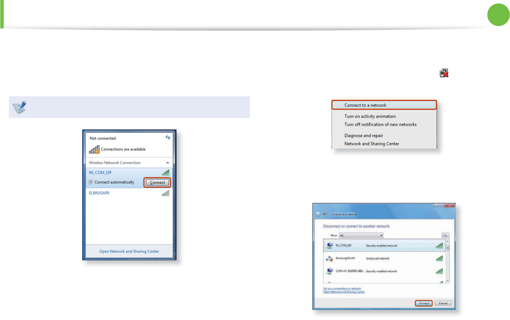
► For Windows Vista
1 Right-click over the Network Connections icon on the
taskbar and click Connect to the Network.
2 Select an AP to connect to and click Connect. If there is a
confi gured network key for the AP to connect to, enter the
network key and then click the Connect button.
3 When Connected to the AP is displayed, click the Close
button. You can access the network.
80
Chapter 2.
Using the computer
Wireless Network (Optional)
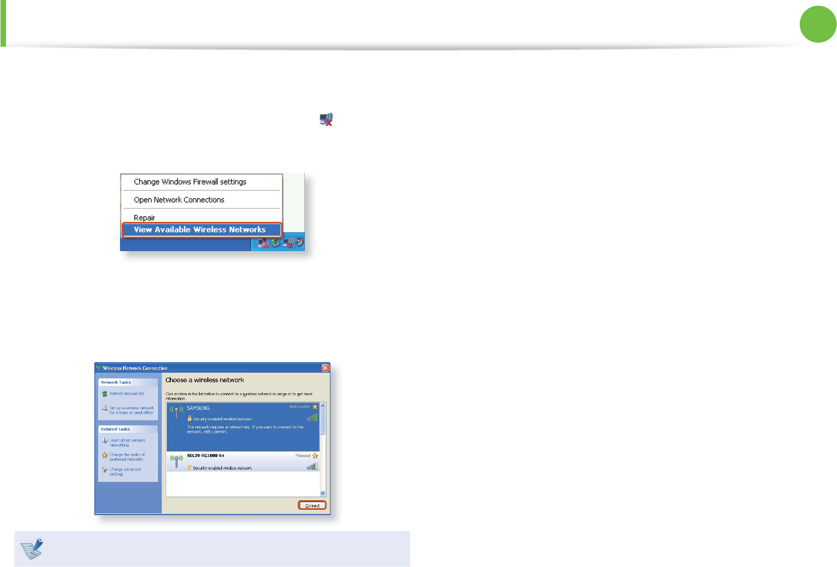
► For Windows XP
1 Click the Wireless Network Connection icon from the
Taskbar using the right button of the touch pad. Then, click
View Available Wireless Networks.
2 Select an AP to be connected and click Connect.
If a network key is set in the AP, the network key input
window will appear. Enter the network key in the input
window and click OK.
For a network key, contact the network administrator.
3 Once Connected to AP is displayed, you can use a wireless
network.
81
Chapter 2.
Using the computer
Wireless Network (Optional)
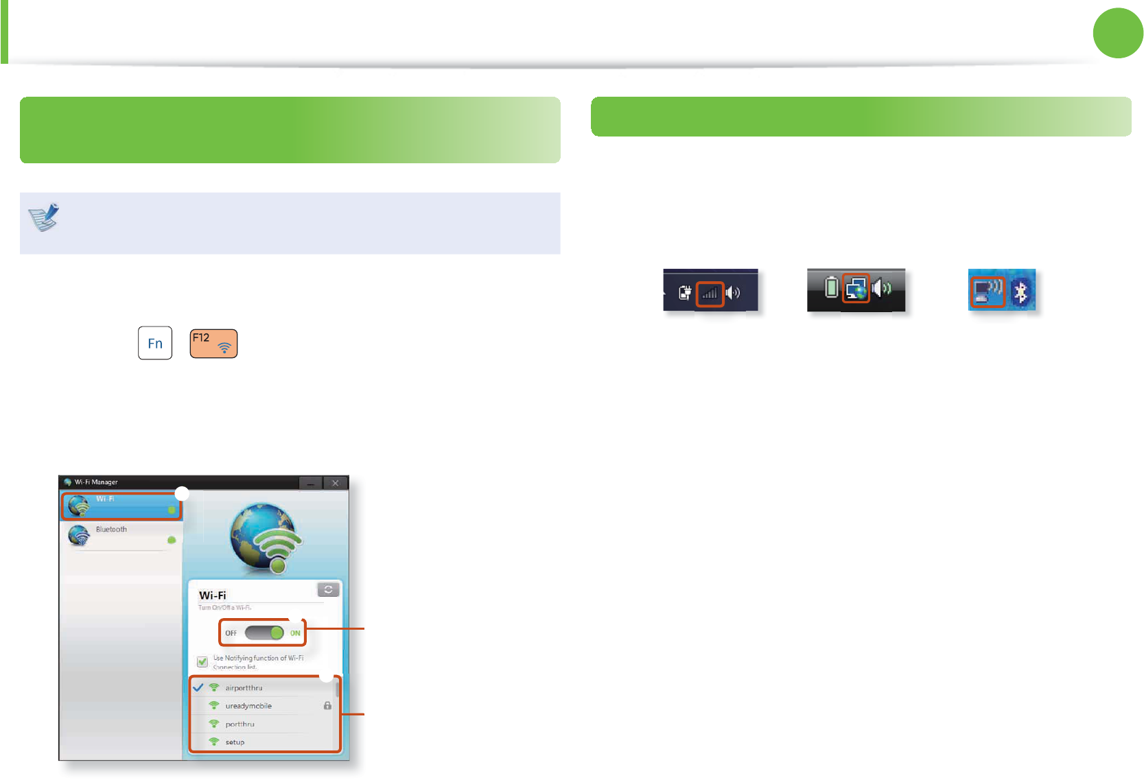
Connecting to a wireless network through Wi-Fi
Manager (Optional)
These descriptions are for Windows 7 and for supported
models only.
You can access a wireless network using Wi-Fi Manager.
1 Press the + key combination. Then the Wi-Fi
Manager window appears.
2 Select Wi-Fi and check if it is set to ON.
If this option is set to ON, the Wi-Fi function will run.
You can set this to
ON or OFF.
AP List
W
l
n
Normal Wireless Network Status
If the wireless LAN icon is displayed in the system tray of the
Taskbar, it indicates that the computer is connected to the Internet
properly (see below).
[Windows 7] [Windows Vista] [Windows XP]
82
Chapter 2.
Using the computer
Wireless Network (Optional)
Abnormal Wireless Network Status
When the wireless LAN is not connected
If the wireless LAN icon is displayed with an “X” in the system
tray of the Taskbar, it indicates that the wireless LAN device is
turned off or that there are no available APs. Or the wireless LAN is
disconnected.
[Windows 7] [Windows Vista] [Windows XP]
If the wireless LAN is turned off , press the + key
combination to turn it on.
When you are not connected to the Internet
This is indicated by the wireless LAN icon in the system tray of
the Taskbar. In this case, you have to check the IP address settings.
Please contact your network administrator and reconfi gure the IP
address.
[Windows 7] [Vista] [Windows XP]
When APs are found but your computer is not
connected to the Internet
This is the case when an AP with a weak signal has been set to
a high priority. Connect to an AP with a strong signal by clicking
it.
An AP with a strong signal strength
The currently connected AP.
The signal strength is low.
Click
[Windows 7]
[Windows XP]
An AP with a strong
signal strength
The currently connected AP.
The signal strength is low.
Click

83
Chapter 2.
Using the computer
Sharing Content in a Home Network (Easy Content Share) (Optional)
Easy Content Share is a DLNA application that allows you to play
photos, videos and music fi les on your TV.
These descriptions are for Windows 7 and for supported t
models only.
The Digital Living Network Alliance (DLNA) aligns industry t
leaders in the CE, mobile, and PC industries through digital
interoperability, and DLNA-certifi ed devices allow users to
play videos, photos and music fi les stored on a computer
on a TV.
To play content using DLNA technology, both your t
computer and TV must be DLNA certifi ed.
For information on whether a product supports DLNA,
refer to the respective user manuals.
To play videos, photos and music fi les stored on a computer,
confi gure the settings in the order as shown below.
1. Confi guring the network settings for your computer and
TV
2. Adding shared content on your computer
3. Playing content on your TV using your computer
Confi guring the network settings for your
computer and TV
To share content, all shared devices must be connected to the
same access point.
Confi gure the network settings by following the steps below.
1 Connect your computer and TV to an access point through
a wired or wireless LAN connection, as shown in the fi gure
below.
[Network connection diagram]
2 Confi gure the IP address settings for your computer and TV.
You must check the Obtain an IP address automatically
(DHCP) checkbox.
84
Chapter 2.
Using the computer
For more information on how to confi gure the IP address t
for your computer, refer to Chapter 2. Using the
Computer > Network.
For more information on how to confi gure the IP address t
for your TV, refer to the user manual of your TV.
3 To check if the network environment has been confi gured,
run Easy Content Share.
If the connected computer and TV are shown in the program
window, the network settings have been confi gured
successfully.
Devices that can share content
If connected devices are not displayed, refer to the Easy
Content Share item in the Troubleshooting Guide.
Adding shared content on your computer
Add the videos, photos and music fi les that you want to play on
your TV as shared items.
You can only play shared items on your TV.
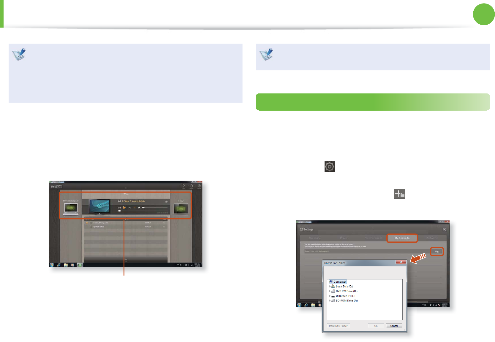
1 Click Settings at the top right of Easy Content Share.
2 Click My computer > Add Folder . The Browse For
Folder window appears. Select a folder to share and click OK.
Sharing Content in a Home Network (Easy Content Share) (Optional)
85
Chapter 2.
Using the computer
3 The selected folder is added to the shared list.
Playing content on your TV using your computer
After you have set photos, videos and music fi les as shared items,
you can play them on your TV using your computer.
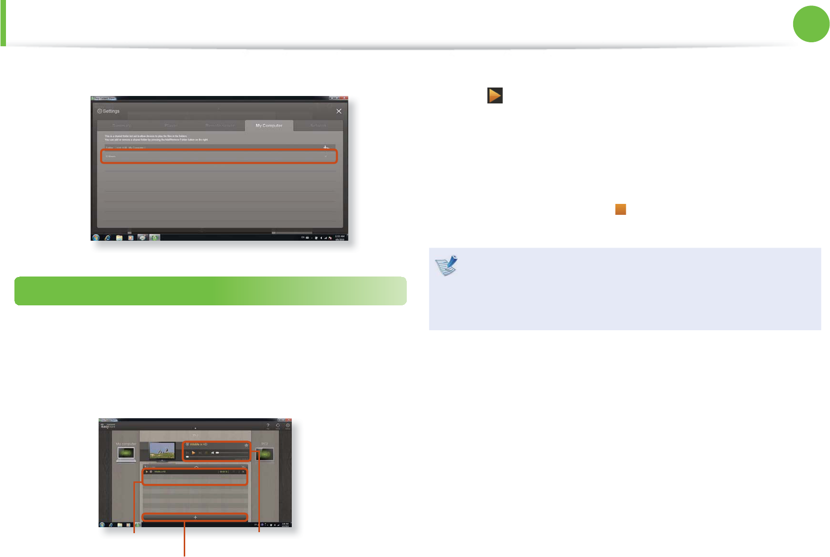
1 In Easy Content Share, select the TV you want to use to play
content.
Playlist
Add content to play
Play control panel
2 Select the item you want to play in the playlist, and then click
Play .
3 The selected fi le is played on the TV.
Using the Play Control panel, you can control the item being
played on the TV.
4 To stop playing, click Stop .
Easy Content Share does not support subtitles due to DLNA
constraints.
To use the caption function, refer to the Easy Content Share
item in the Troubleshooting Guide.
Sharing Content in a Home Network (Easy Content Share) (Optional)
86
Chapter 2.
Using the computer
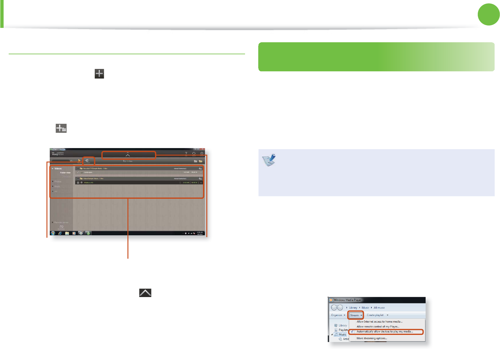
Adding a video, photo or music fi le to the playlist
1 Click Add Content in the Playlist screen. The shared
content list is displayed.
2 In the shared content list, check the checkbox in front of the
item you want to add to the playlist, and then click Add to
playlist .
Add the selected
item to the playlist
Shared content list
Return to the
playlist screen
3 Click Return to playlist screen .
In the playlist screen, you can fi nd that the selected item has
been added to the playlist.
Playing the content stored on a computer when
Easy Content Share is not installed
You can also play the videos, photos and music fi les stored on a
computer when Easy Content Share is not installed on your TV
by using Windows Media Player.
As described in the steps below, confi gure the content sharing
settings to play content on your TV.
The computer containing the shared content (when Easy
Content Share is not installed) must be connected to the
same access point to which the computer where Easy
Content Share is installed and the TV is connected to.
► For Windows Media Player 12
1 Run Windows Media Player.
2 Click Stream and check the Automatically allow devices to
play my media... menu item.
Sharing Content in a Home Network (Easy Content Share) (Optional)
87
Chapter 2.
Using the computer
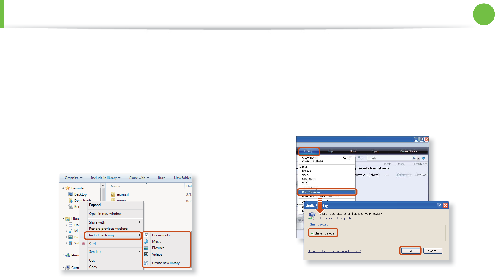
3 Run Windows Explorer.
4 Right-click the folder to share. From the menu displayed,
point to Include in library.
Click Videos, Photos or Music in the displayed sub menu,
according to the type of content contained in the selected
folder.
If the selected folder contains two or more types of content,
you must click each corresponding menu item (Videos,
Photos or Music) to register each type of content.
► For Windows Media Player 11
1 Run Windows Media Player.
2 Click Library > Media Sharing.
The Media Sharing window is displayed. Check the Share
my media checkbox and then click OK.
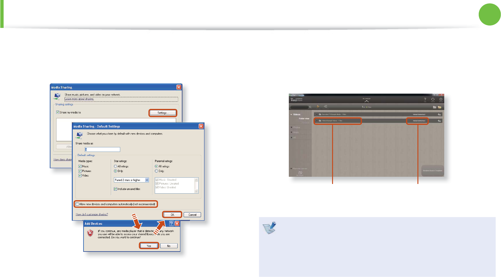
3 In the Media Sharing window, click Settings.... The Media
Sharing - Default Settings window is displayed. Check the
Allow new devices and computers automatically (not
recommended) checkbox.
Sharing Content in a Home Network (Easy Content Share) (Optional)
88
Chapter 2.
Using the computer
A popup window is displayed. Click Yes. Then click OK in the
Media Sharing- Default Settings window and in the Media
Sharing window.
After the registration has been fi nished, you can fi nd the added
folder is listed in the shared content list of Easy Content Share.
For a shared content item, the name of the computer where the
item is stored is displayed next to it, allowing you to identify the
computer. This is useful when multiple computers are providing
content.
A folder added as a
shared item
The name of the PC where
the content is stored
Content sharing is only available with Windows Media
Player 11 or later.
If your Windows Media Player is earlier than Windows
Media Player 11, download and install Windows Media
Player 11 or later from the Microsoft website.
Sharing Content in a Home Network (Easy Content Share) (Optional)
89
Chapter 2.
Using the computer
HDD Protection Function (Optional)
This function protects the HDD from external impacts while
operating by using the 3-axis sensor that detects inclinations,
movement and vibrations.
Through the icon colors, the HDD protection status can be
identified. You can activate or deactivate the function by right-
clicking over the icon in the taskbar.
Icon Color Operating Status
The HDD protection function is activated.
The HDD protection function is deactivated.
The HDD has received an impact and the HDD
protection function is currently running.
To set the sensitivity of the protection function, right-click the icon
, and select Open Control Panel.
Sensitivity Operating Status
High Select this option for operating environments with
no possibility of shocks (default).
Medium
Select this option for operating environments with
the possibility of slight shocks (e.g. in a vehicle or on
a lap).
Low Select this option for operating environments with a
possibility of severe shocks (not recommended).
If external movement (e.g. if a user moves or the vehicle t
carrying the computer moves) is detected while the HDD is
in operation such as watching a video or copying data, the
current operation and the HDD are stopped accordingly.
If the external movement stops, the paused operation t
resumes after approximately 3 seconds.
Can’t be guaranteed the prevention of damage to hard t
disk and protection data under all circumstances.
90
Chapter 2.
Using the computer
Using the Security Device (Optional)
You can protect your computer using the security device and
program installed on the computer.
The OmniPass security program is installed on this computer.
This is a powerful security program that enables you to set
a password for the Windows user’s account information and
provides TPM, Smart Card and fi ngerprint recognition functions.
To use the OmniPass program, you have to complete the following
procedures.
Step 1 : Registering a User
Step 2 : Registering Authentication Device
Step 3 : Using the Security Device
This function is only supported for models with Smart Card t
reader, TPM chip and fi ngerprint recognition devices. The
type of authentication device may diff er depending on the
model.
The Omnipass security program may not be provided or t
a diff erent version may be provided depending on the
model.
The screen image, terms and usage are subject to change t
depending on the version.
For more information, refer to the help of the program.t
Step 1 : Registering a User
You have to register a user after logging in with a registered
Windows user account.
1 Click Start > All Programs > Omnipass > OmniPass
Enrollment Wizard and then Start.
2 Enter the Windows user account and password and click
Next.
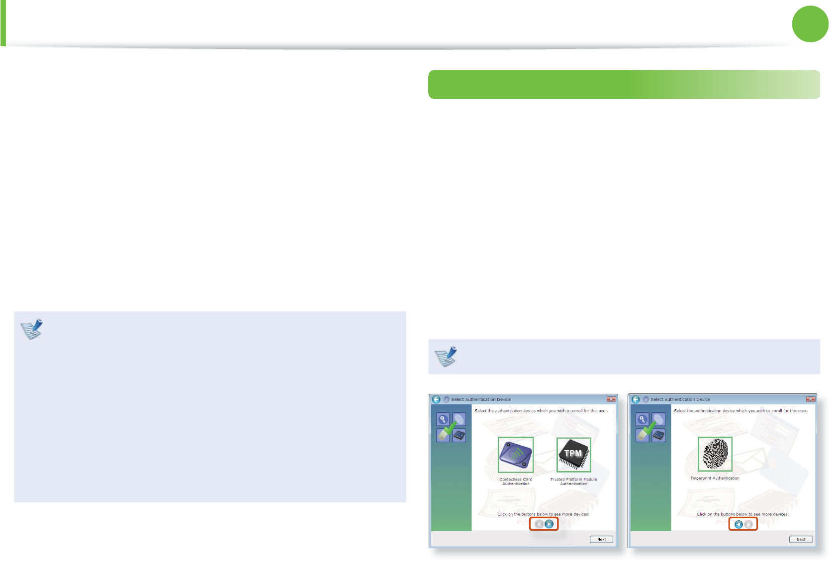
3 Select an authentication device to be registered for the
entered user account. You cannot register more than one
authentication device.
The type of device may diff er depending on the model.

91
Chapter 2.
Using the computer
Using the Security Device (Optional)
Step 2 : Registering Authentication Device
Registering as a TPM Device (Optional)
The TPM (Trusted Platform Module) saves the user authentication
information on the TPM chip installed on the computer.
Before registering a device as a TPM device, check if the TPM
program has been installed, initialize the TPM chip and register
the user.
1. Initializing the Chip
When you use the TPM function for the fi rst time or you want to
delete the user information saved on the TPM chip, complete the
following.
If the TPM chip is initialized, all the authentication t
information saved on the TPM chip is deleted. Therefore,
please be careful.
After initializing the TPM chip, you cannot use the fi les and t
folders encrypted by the TPM function. Therefore, decrypt
them before initializing the chip.
Either type A or B is provided depending on the model. t
1 Turn the computer on, and if the booting screen (SAMSUNG
logo) appears, press the F2 key.
► Type A Model
If the BIOS screen appears, select Security > TPM
Confi guration, set the TPM Support item to Enabled and
set the Change TPM State item to Clear.
► Type B Model
If the BIOS screen appears, select Advanced > Trusted
Computing, and set the TPM Support item to Enable, the
TPM State to Enabled and the Pending TPM operation to
TPM Clear.
3 Press the F10 key to save the settings.
4 When the booting screen (SAMSUNG logo) appears, press the
F2 key.
If the message window appears, press the F12 key.
When the computer restarts automatically, press the F2 key.

92
Chapter 2.
Using the computer
Using the Security Device (Optional)
► Type A Model
When the BIOS screen appears, select Security > TPM
Confi guration and set the Change TPM State item to
Enable & Activate.
► Type B Model
If the BIOS screen appears, select Advanced > Trusted
Computing, and set the TPM Support item to Enable, the
TPM State to Enabled and the Pending TPM operation to
Enable Take Ownership.
6 Press the F10 key to save the settings.
If the message window appears, press the F10 key.
7 Now that the TPM chip initialization has been completed, you
can register a user.
2. Registering a User
Complete the following only when you want to register a user to
the TPM chip.
1 Click Start > All Programs > Infi neon Security Platform
Solution > Manage Security Platform and select the User
Settings tab.
2 The security authentication confi guration begins with the
instructions of the Initialization Wizard. Select a drive to
save the authentication information to and click Next.
3 Select a Security Platform function to use and set
the password. If you click Next, the Security Platform
confi guration begins.
4 When the Initialization Wizard completion window appears,
click Finish to fi nish the user registration. You can now use
the TPM device of the OmniPass program.
93
Chapter 2.
Using the computer
3. Registering the TPM
1 In the OmniPass program screen, select Trusted Platform
Module Chip and click Next.
2 Enter the password for the user who is registered to the TPM
chip and click OK.
3 The TPM chip registration has been completed.
Check whether to fi nish the registration or register more
security authentication devices and click Next.
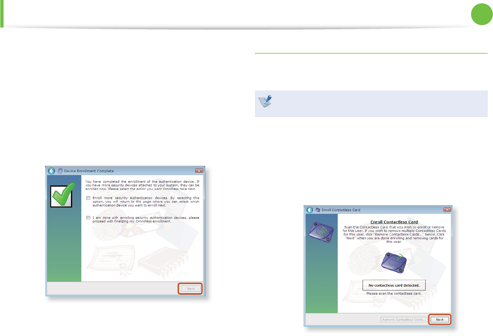
Registering the Smart Card (Optional)
Read the Smart Card information and register it to the Windows
user account.
A smart card is a type of RFID device. This product only
supports smart cards from among RFID devices.
1 In the OmniPass program screen, select Contactless Card
Authentication and click Next.
2 If you place the smart card to be registered in the reader (the
right space of the touchpad), the smart card information is
automatically read.
Using the Security Device (Optional)
94
Chapter 2.
Using the computer
Using the Security Device (Optional)
Place smartcard
here.
3 The authentication device has been registered. Check
whether to fi nish the registration or register more security
authentication devices and click Next.
Supported cards:
- ISO14443-4 Type A / Type B
- Innovision Jewel
- Mifare Family
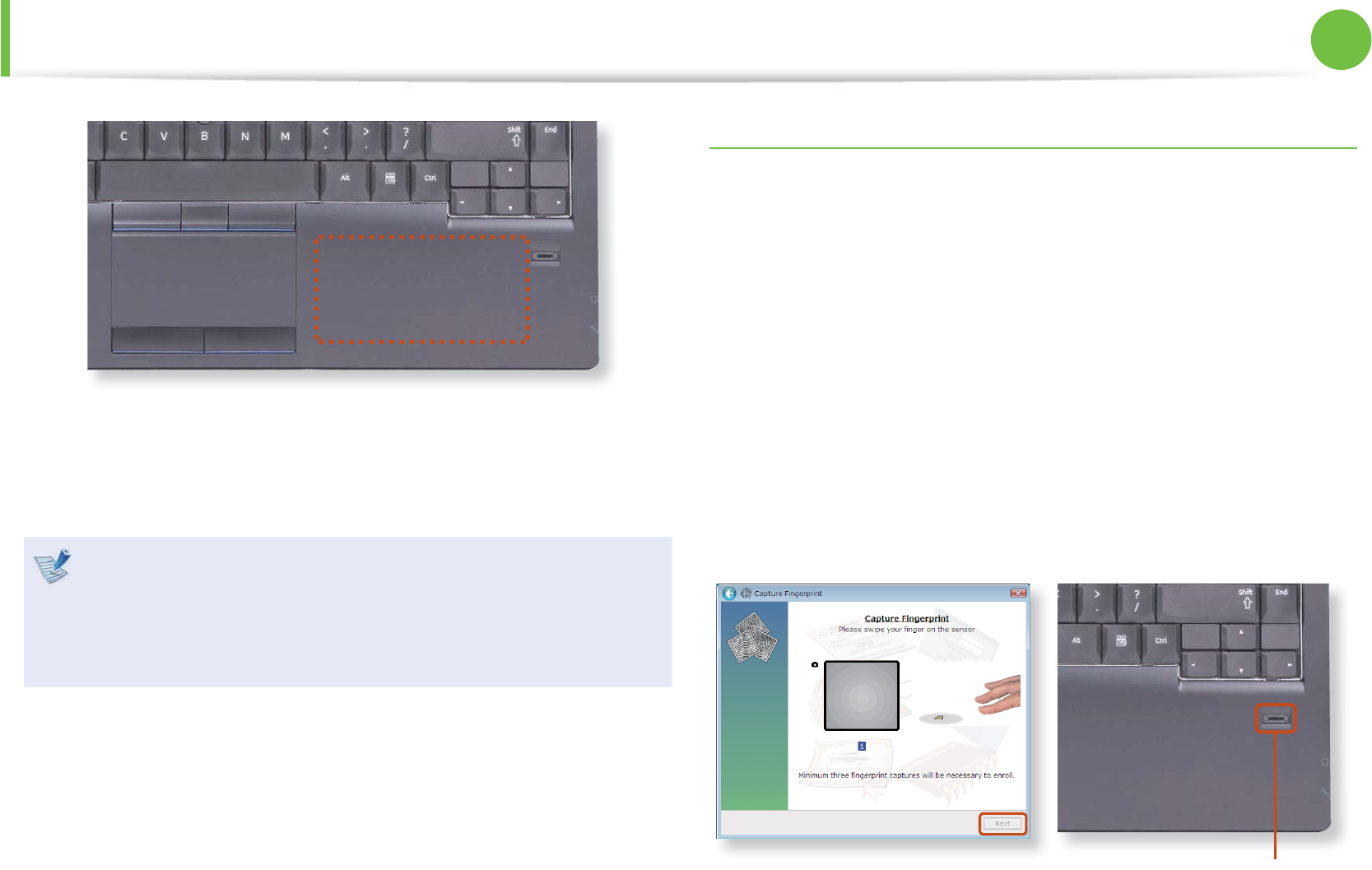
Registering Fingerprints (Optional)
You can register fi ngerprints and register them to a Windows user
account. You can register the fi ngerprint of a particular fi nger and
register up to 10 fi ngerprints.
1 In the OmniPass program screen, select Fingerprint
Authentication and click Next.
2 Select the fi ngers to be registered and click Next.
3 Move your fi ngers on the fi ngerprint recognition device
according to the instructions displayed on the screen. At least
3 fi nger prints are captured.
Fingerprint Sensor
95
Chapter 2.
Using the computer
Using the Security Device (Optional)
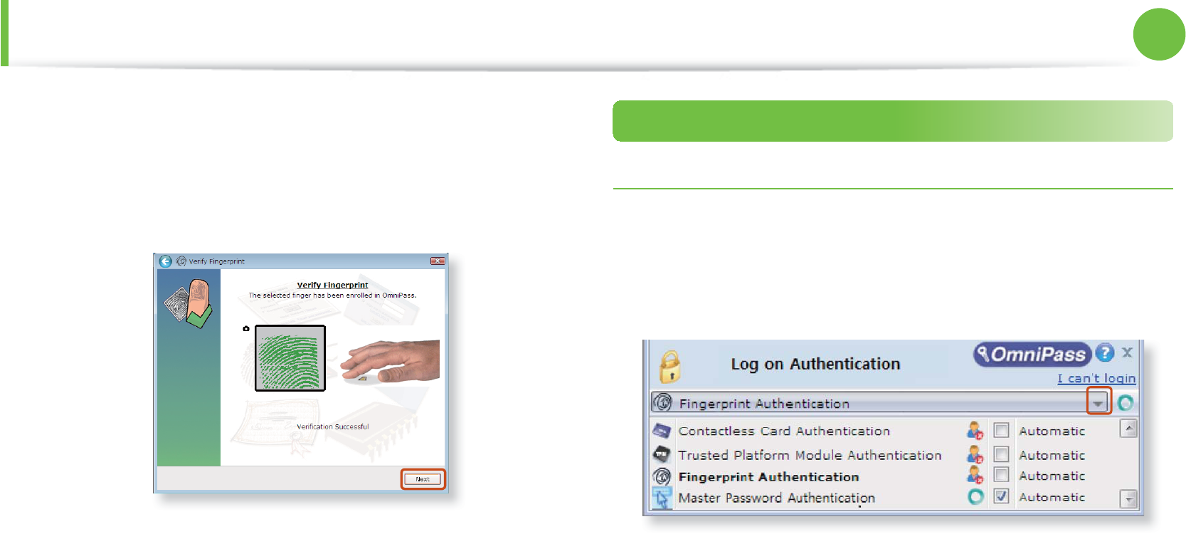
4 Finally, confi rm that the captured fi ngerprints are your fi ngers.
If a green fi ngerprint is displayed on the screen, it indicates
that the selected fi nger has been properly registered. Click
Next. (If a red fi ngerprint is displayed on the screen, register
the fi nger again.)
5 If the message window appears, determine whether to
register more fi ngers.
6 The fi ngerprint registration has been completed.
Check whether to fi nish the registration or register more
security authentication devices and click Next.
Step 3 : Using the Security Device
Logging into Windows
1 If you turn the computer on, the authentication window
appears in the login screen. If there is more than one
authentication device, you can select one of them by pressing
the right arrow.
2 If the authentication process is complete, you will be logged
into Windows.
96
Chapter 2.
Using the computer
Using the Security Device (Optional)
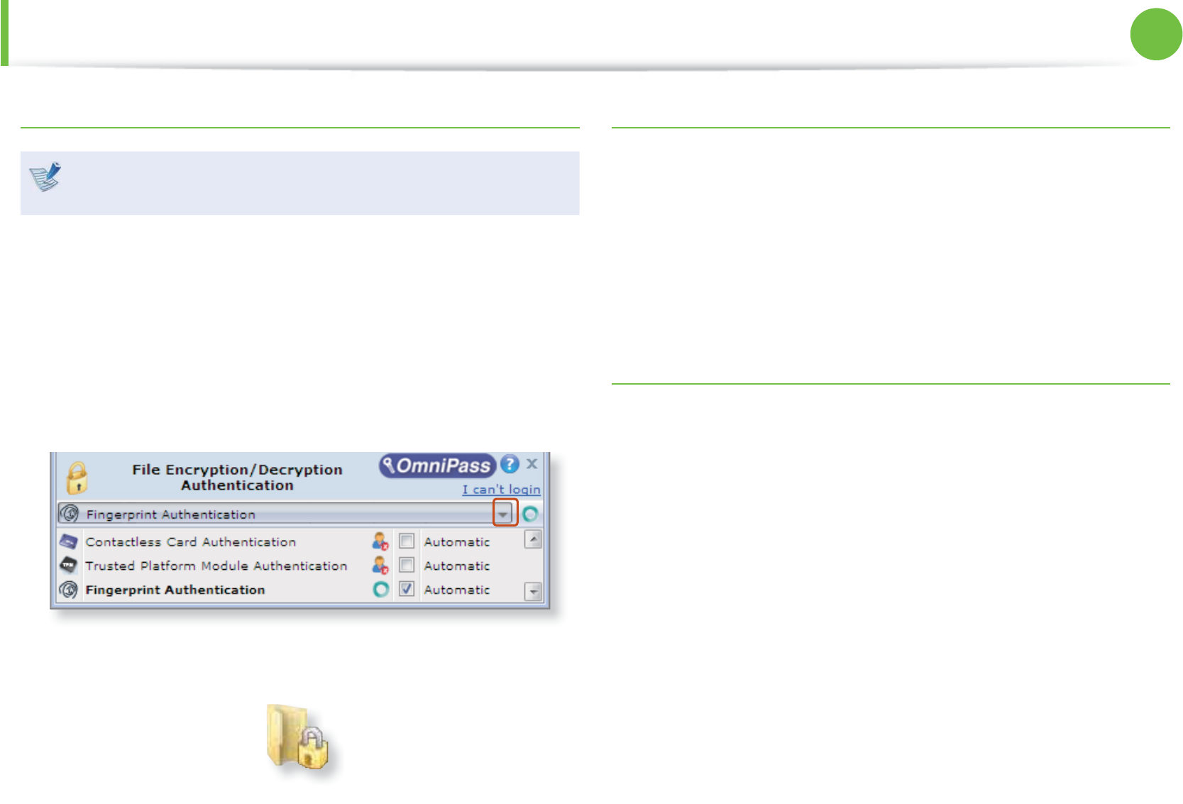
Encrypting Folder
You cannot encrypt a fi le or folder that is stored directly
under the C drive. ex) C:\Samsung
1 Place the pointer over a folder to be encrypted and select
OmniPass Encrypt File(s).
2 Encrypt the folder through the authentication device
registered to the Windows account that is logged in.
If there is more than one authentication device registered to
the user account, you can select one of them by pressing the
right arrow.
3 When the folder is encrypted, you will be able to view the
lock icon in the folder icon.
Opening an Encrypted Folder
1 Double-click an encrypted folder.
2 If the authentication screen appears, select an authentication
device and enter the registered password.
3 The folder opens.
Decrypting an Encrypted Folder
1 Place the pointer over an encrypted folder and select
OmniPass Decrypt File(s).
2 If the authentication screen appears, select an authentication
device and enter the registered password.
3 The folder is decrypted.

LCD Brightness Control 98
BIOS Setup 100
Setting a Boot Password 102
Changing the Boot Priority 105
Upgrading Memory 106
Battery 109
Using the Security Lock Port 116
Chapter 3.
Settings and Upgrade

98
Chapter 3.
Settings and Upgrade
LCD Brightness Control
You can adjust the LCD brightness in 8 levels.
The screen brightness is automatically set to the brightest
level (brightness level 8) when AC power is connected and the
brightness is automatically set dimmer when the computer
runs on battery power to extend the battery use time.
Controlling the Brightness Using the Keyboard
Adjust the LCD brightness by pressing the + key or the
+ key.
The LCD brightness can change up to 8 levels and the brightness
increases by 1 level when pressing the + key once.
Maintaining the changed LCD brightness even after t
turning the computer on again
To maintain the LCD brightness set by using the brightness
control keys or through the Power Options, follow the
procedures below.
► For Windows 7/Vista
1. Click Control Panel > Hardware and Sound > Power
Options.
2. Click Change the settings of the currently confi gured
mode.
3. Adjust the display brightness adjustment menu bar and
click the Save the changes button.
Saving battery power consumption
Decreases the LCD brightness when the computer
is running on battery power to save battery power
consumption.

99
Chapter 3.
Settings and Upgrade
LCD Brightness Control
LCD bad pixels principle of laptop computert
Samsung observes the specifi cations regarding strict
quality and reliability of LCD. But in spite of that, it is
inevitable that there might be a small number of bad
pixels. A large number of bad pixels can cause problems in
appearance, but a small number of pixels doesn’t aff ect the
computer performance.
Therefore Samsung observes and manages the following
dot principles:
- Bright dot : 2 or less
- Black dot : 4 or less
- Combination of Bright and Dark : 4 or less
Instructions for Cleaning the LCD
Clean the LCD panel with a soft cloth lightly moistened with
computer cleansing detergent moving in one direction.
Cleaning the LCD panel with excessive force can damage the
LCD.
100
Chapter 3.
Settings and Upgrade
BIOS Setup
The BIOS Setup enables you to confi gure your computer hardware
according to your needs.
Use the BIOS setup to defi ne a boot password, change the t
booting priority, or add a new device.
Since incorrect settings may cause your system to t
malfunction or crash, take care when confi guring the BIOS.
The functions of the BIOS setup are subject to change for t
product function enhancement purposes.
The BIOS Setup menus and items may diff er depending on t
your computer model.
Entering the BIOS Setup
1 Turn the computer on.
2 When the booting screen (SAMSUNG logo) appears, press the
F2 key to enter the BIOS Setup.
The screen images in this document may diff er from actual
product.
3 After a moment, the BIOS setup screen appears.
The items in the BIOS setup may diff er depending on the
product.
101
Chapter 3.
Settings and Upgrade
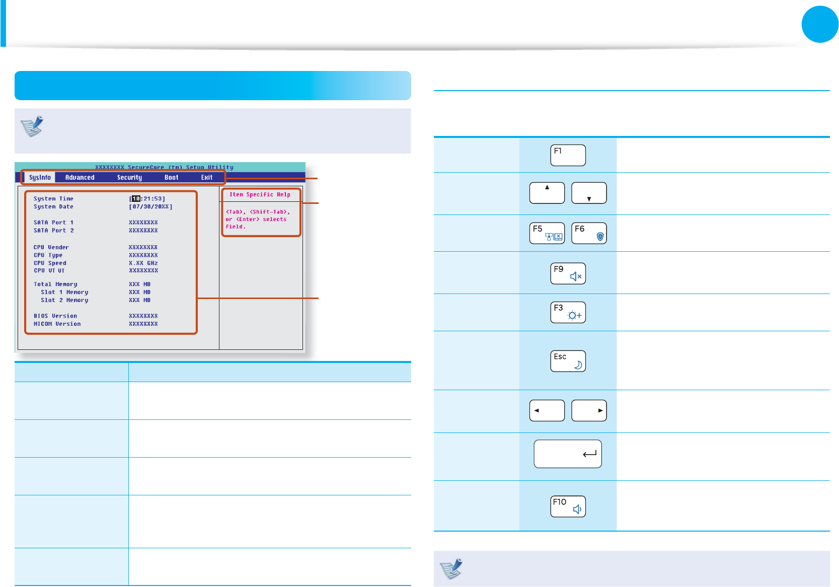
The BIOS Setup Screen
The BIOS Setup menus and items may diff er depending on
your computer model.
( - x)
Setup Menu
Setup Items
Help
Help for the
selected
item appears
automatically.
Setup Menu Description
SysInfo This is a description about the basic
specifi cations of the computer.
Advanced Using this menu, you can confi gure the major
chipsets and additional functions.
Security Used to confi gure security functions, including
passwords.
Boot
This menu enables you to confi gure
peripherals and booting related settings such
as the boot priority.
Exit Used to exit the Setup either saving the
changes or not.
System Setup Keys
In the Setup, you have to use the keyboard.
F1 Press to view the Setup Help.
Up & Down
Keys Press to move up and down.
F5/F6 Press to change the item value.
F9 Press to load the default Setup
settings.
F3 Press to restore the previous value.
ESC
Press to return to a higher level
menu or to move to the Exit
menu.
Left & Right
Keys Press to move to another menu.
Enter Press to select an item or to enter a
sub menu.
F10 Press to save the changes and exit
Setup.
The keyboard image may diff er from the actual keyboard.
BIOS Setup
102
Chapter 3.
Settings and Upgrade
Setting a Boot Password
When setting a password, you have to enter a password to use the
computer or enter the BIOS Setup.
By confi guring a password, you can restrict system access to
authorized users only and protect data and fi les saved on the
computer.
Do not lose or forget your password. t
If you have forgotten your password, contact a Samsung t
service center. In this case, a service fee will be charged.
The screen images and terms may diff er from actual t
product depending on the computer model and driver
version.
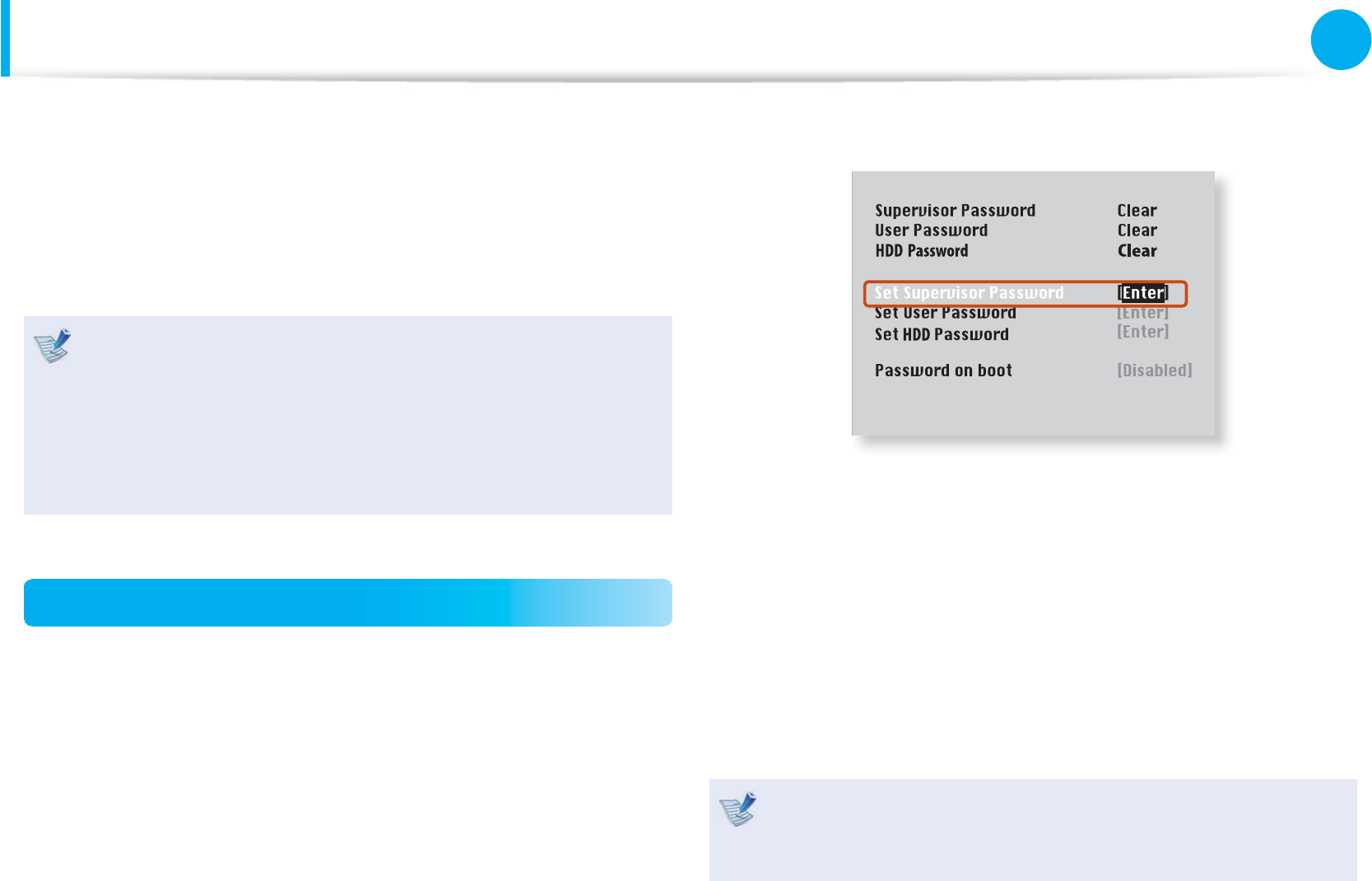
Setting a Supervisor Password
A Supervisor Password is required to turn the computer on or to
start the System Setup.
When setting a Supervisor Password, users other than a supervisor
cannot use the computer.
1 Select the Security menu in the BIOS Setup.
2 In the Set Supervisor Password item, press <Enter>.
3 Enter a password, press <Enter>, re-enter the password for
confi rmation, and press <Enter> again.
The password can be up to 8 alphanumeric characters.
Special characters are not allowed.
4 The supervisor password has been set.
The supervisor password is required to turn the computer on
or to enter the BIOS Setup.
For some models, if the password entered message appears
in the Setup Notice window, the settings are not complete
until the <Enter> key is pressed.

103
Chapter 3.
Settings and Upgrade
Setting a Boot Password
Setting a User Password
Users can start the system with a user password, but cannot enter
the System Setup. By doing this, you can prevent other users from
entering Setup.
Before configuring a user password, a supervisor password must
have been configured. Deactivating the supervisor password also
deactivates the user password.
In the Set User Password item, press <Enter> and complete the
procedures from Step 3 of Setting a Supervisor Password.
Setting Up a Boot Password
To setup a boot password, the administrator password (Set
Supervisor Password) should be set in advance.
Set the Password on boot item to Enabled.
Once a boot password is set, you have to enter a password to boot
up the computer.
Setting up a Hard Disk Drive Password
(Optional)
If you set a password for a hard disk drive, it cannot be accessed
from another computer.
Press <Enter> in the Set HDD Password item and define a
password as described in Step 3 of the Setting up the Supervisor
Password.
The hard disk drive password setting function is not t
provided for some models.
Changing the hard disk drive passwordt
For security purposes, you can only change a hard disk
drive password after restarting the computer by pressing
the computer Power button.
If you cannot change the hard disk drive password or the
HDD Password Frozen message appears when entering
the BIOS Setup and then selecting Security > HDD
Password, press the Power button to turn the computer
on again.

104
Chapter 3.
Settings and Upgrade
Setting a Boot Password
Deactivating the Password
1 Press <Enter> on the password to be deactivated. For
example, to deactivate a supervisor password in the Set
Supervisor Password item, press <Enter>.
2 In the Enter Current Password item, enter the currently
confi gured password and press <Enter>.
3 Leave the Enter New Password item fi eld empty, and press
<Enter>.
4 Leave the Confi rm New Password fi eld empty, and press
<Enter>.
The password is deactivated.
For some models the password is only canceled if the
<Enter> key is pressed in the Setup Notice window.
105
Chapter 3.
Settings and Upgrade
Changing the Boot Priority
By default, the highest boot priority device is set to the CD-ROM/
DVD drive. As an example, the procedures to change the highest
boot priority device to the hard disk drive are described below.
The screen images and terms may diff er from actual product
depending on the computer model and driver version.
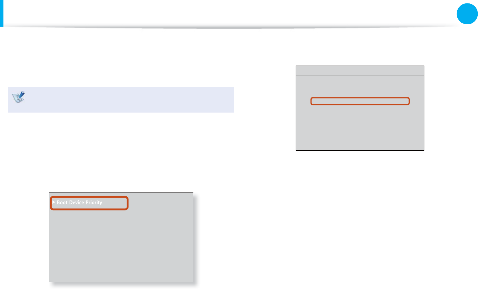
1 Select the Boot menu in the BIOS Setup.
2 Press <Enter> on the Boot Device Priority item.
0WO.QEM =1HH?
6QWEJ2CF/QWUG ='PCDNGF?
+PVGTPCN.#0 ='PCDNGF?
2:'1241/ =&KUCDNGF?
5OCTV$CVVGT[%CNKDTCVKQP
3 Press the down key (↓) to move to the SATA HDD item and
press the F6 key to move up to the top item.
Boot Device Priority
[Set Boot Priority]
1. SATA CD : XXXXXXXXXXXX
2. SATA HDD : XXXXXXXXXXXX
3. USB CD : N/A
4. USB KEY : N/A
5. USB FDD : N/A
6. USB HDD : N/A
7. NETWORK : N/A
4 Press the F10 key to save the settings and exit Setup.
The highest boot priority device is now set to the Hard Drive.
106
Chapter 3.
Settings and Upgrade
Upgrading Memory
One or more memory modules are installed on the computer.
There are 2 memory slots and users can replace the installed
memory or add new memory.
Replace or install new memory only after shutting the t
computer down completely. Do not replace or install
memory when the computer is in Sleep mode.
Disconnect main power plug and remove the battery
before continuing.
To utilize the dual channel feature, using memory modules t
with the same specifi cations (of the same capacity and
from the same manufacturer) is recommended.
The images used for the illustration are of a representative t
model, therefore the images may diff er from the the actual
product.
Adding or Replacing Memory Modules
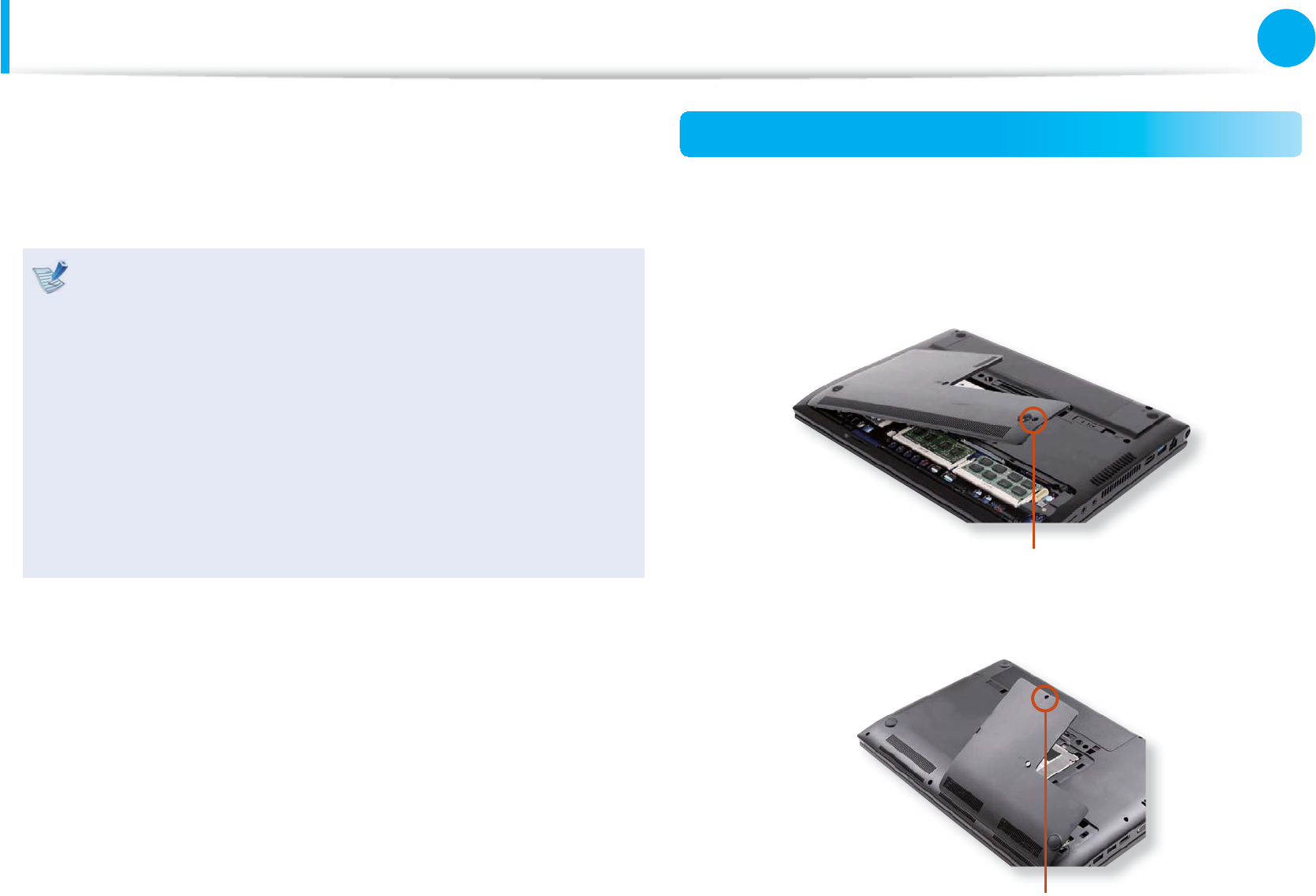
1 Remove the screw on the memory compartment cover at the
bottom of the computer using a screw driver.
► For 12.5 inch models
Fixing Screw
► For 14, 15.6 inch models
Fixing Screw
107
Chapter 3.
Settings and Upgrade
Upgrading Memory
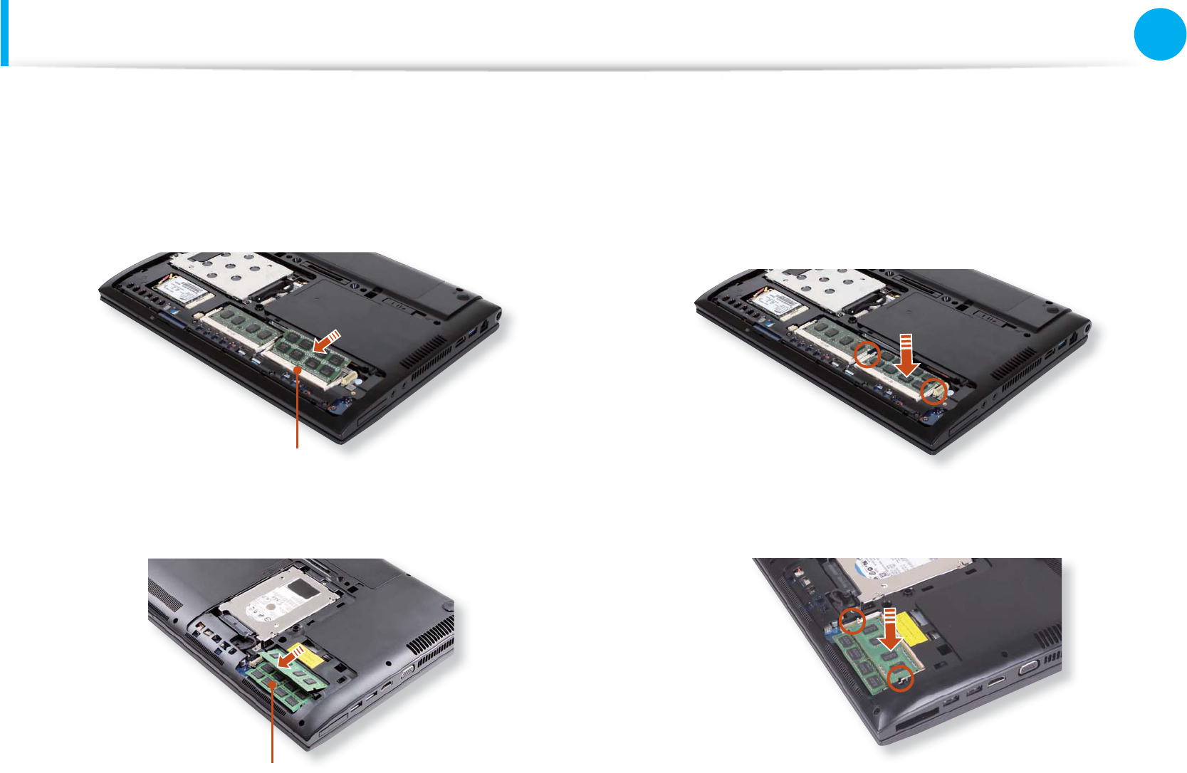
2 Insert a new memory module into the memory slot at an
angle of approximately 30 degrees aligning it to the angle of
the memory slot.
► For 12.5 inch models
Memory Slot
► For 14, 15.6 inch models
Memory Slot
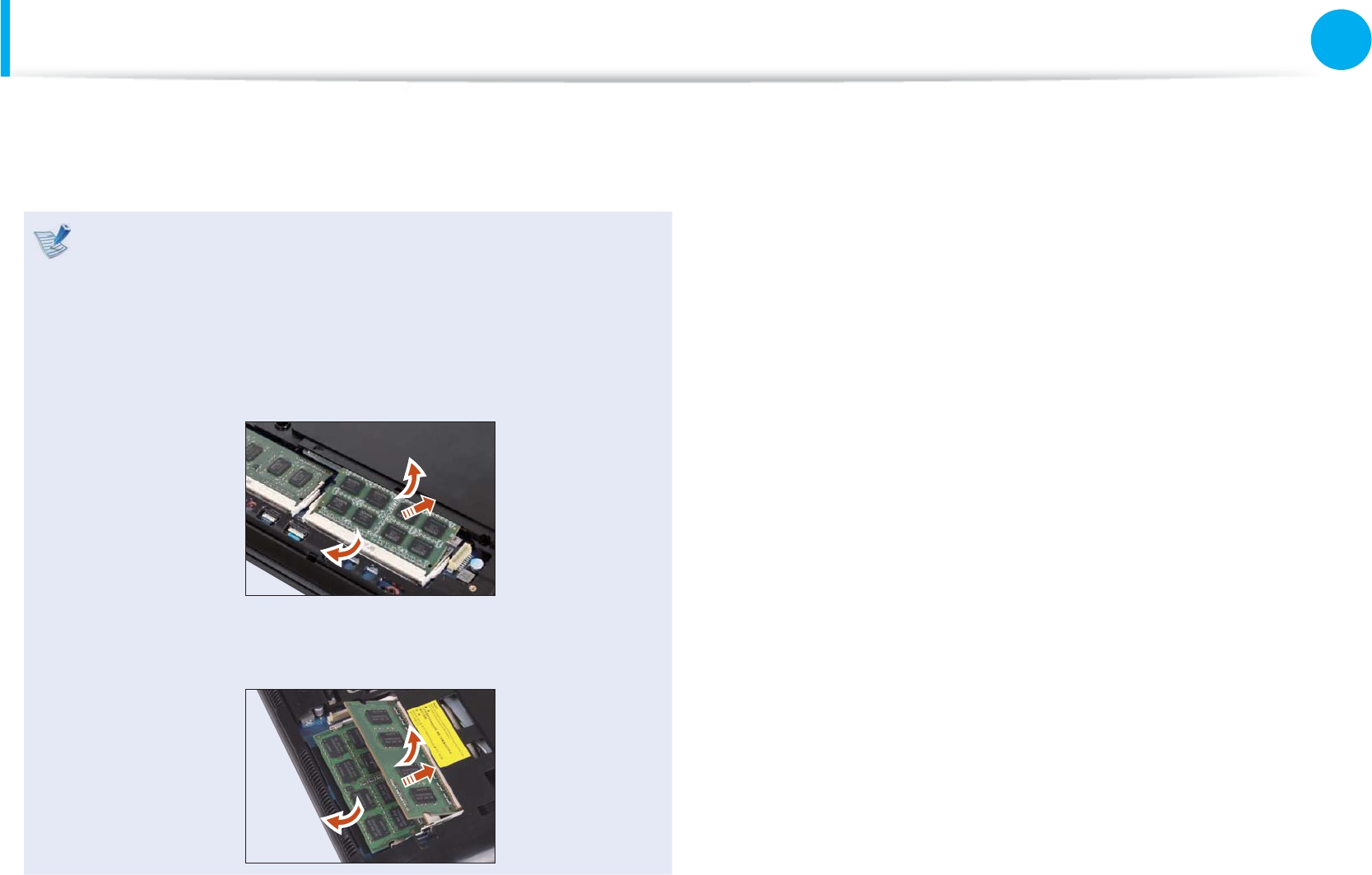
3 Push the memory module down so that it is completely fi xed.
If the memory does not fi t easily, push the memory module
down while pulling the memory module latches outward.
► For 12.5 inch models
► For 14, 15.6 inch models
108
Chapter 3.
Settings and Upgrade
Upgrading Memory
4 Close the memory compartment cover and fasten the screw.
Removing a memory module
Pull the memory module latches outward.
The memory module will pop up.
Remove the memory module out at an angle of 30 degrees.
► For 12.5 inch models
► For 14, 15.6 inch models
109
Chapter 3.
Settings and Upgrade
Battery
Please refer to the following instructions when running the
computer on battery power without connecting the AC power.
A Lithium-Ion smart battery is supplied with this computer.
Carefully read and follow the precautions printed on the t
battery before using the battery.
Before using your computer for the fi rst time after t
purchasing it, charge the battery completely.
The images used for the illustration are of a representative t
model, therefore the images may diff er from the the actual
product.
Precautions
Use only chargers specifi ed in the User Manual.t
Never heat the battery pack, put it near or in a fi re or use at t
a temperature higher than 60°C, as this may cause fi re.
Never cause a short circuit between the battery pack t
terminals or disassemble the battery pack.
Carefully read and follow the precautions printed on the t
battery and the safety instructions in the User Manual
before using the battery.
Please refer to the system operation environment of t
this manual and operate and store the battery at room
temperature.
Charging the Battery
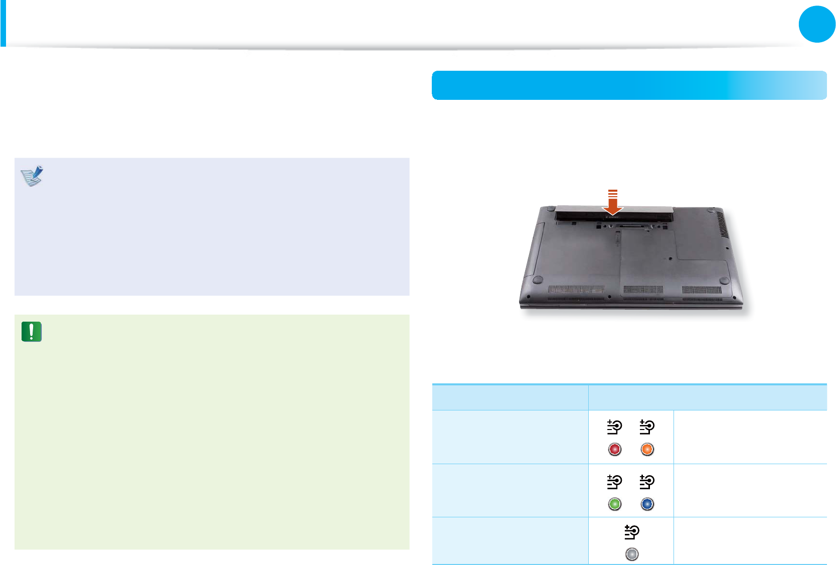
1 Attach the battery and connect the AC adapter to the DC-in
jack of the computer.
The battery will then start charging.
2 When charging is complete, the Charge LED turns green.
Status Charge LED
Charging Red or Orange
Charging complete Green or Blue
AC adapter not
connected Off
110
Chapter 3.
Settings and Upgrade
Battery
Measuring the Remaining Battery Charge
You can view the battery charge status by completing the
following procedures.
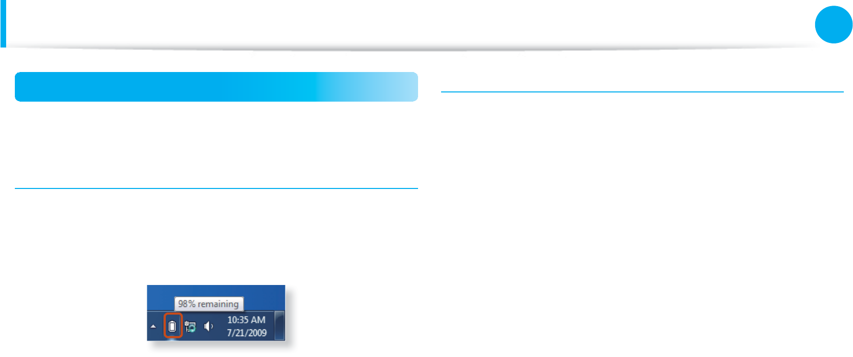
Confi rming the battery charge in the Taskbar
Disconnect the AC adapter and move the mouse cursor over
the battery icon in the system tray of the Taskbar to confi rm the
remaining battery charge.
Battery Usage Time Information
A battery is an expendable supply, so when using it over a long
time, the capacity/battery life is shortened. If the battery life is
reduced to under half of its initial time, we recommend purchasing
a new battery.
When not using the battery for a long time, store the battery after
charging it to 30-40% of its capacity. This extends the battery life
time.
111
Chapter 3.
Settings and Upgrade
Battery
Extending the Battery Usage Time
Decreasing the LCD Brightness
Press the + keys on the keyboard to decrease the LCD
brightness to extend the battery usage time.
Using the battery mode (Optional)
Press the Fn + F8 key combination. The battery mode window will
appear that helps you to use the battery effi ciently. The battery
modes optimized for the operating environment are supported.
These descriptions are for Windows 7 and for supported
models only.
Using the battery modes
To use the power options of the Easy Display Manager
program after reinstalling Windows, you can install the Easy
Display Manager program using the system software media.
Since the battery mode is optimized to extend the battery
use time, programs that require high performance may slow
down when the computer is running on battery power.
In this case, it is recommended connecting the AC adapter or
selecting high-performance mode.
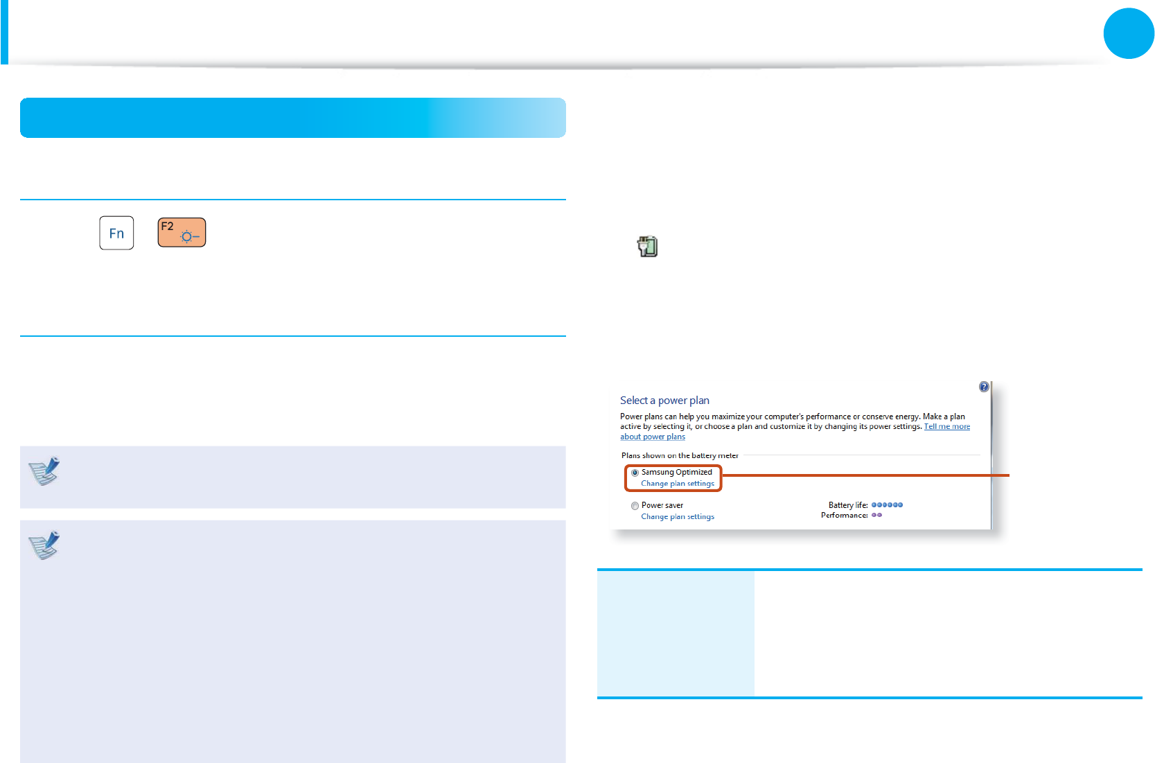
► For Windows 7/Vista
1 Click Start > Control Panel > Hardware and Sound >
Power Options.
Alternatively, right-click the power measuring device icon
in the notifi cation area of the taskbar and select Power
Options.
2 If the following screen appears, select one of the modes.
Samsung
Optimized
Samsung
Optimized
This mode is appropriate for normal conditions.
It maximizes the system performance when
the computer is running on AC power while
maximizing the battery usage time when the
computer is running on battery power.
112
Chapter 3.
Settings and Upgrade
Battery
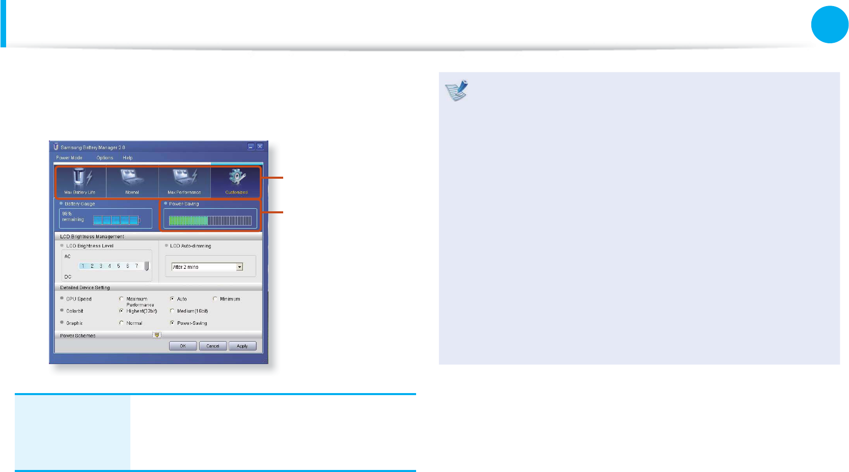
► For Windows XP
Click Samsung Battery Manager.
Select Power
Mode
Power-saving
Eff ect
Maximum
Battery Mode
This mode is appropriate for the environment
that requires maximum battery lifetime. The
system performance may be degraded in this
mode.
What is the Power-saving Eff ect?t
This product displays the battery life in each power mode.
The higher the power saving eff ect increases, the longer
the graph bar is displayed.
When Using Games or Multimediat
The system may not operate properly in maximum battery
mode. It is recommended to connect the AC adapter to the
system or to use the system in general mode.
Usage Mode of Samsung Battery Managert
- The maximum battery mode optimizes the system
operation speed to increase the battery run time, so the
program execution time may get longer.
- If you change the power settings, the properties in Power
Options window will also be changed.
113
Chapter 3.
Settings and Upgrade
Battery
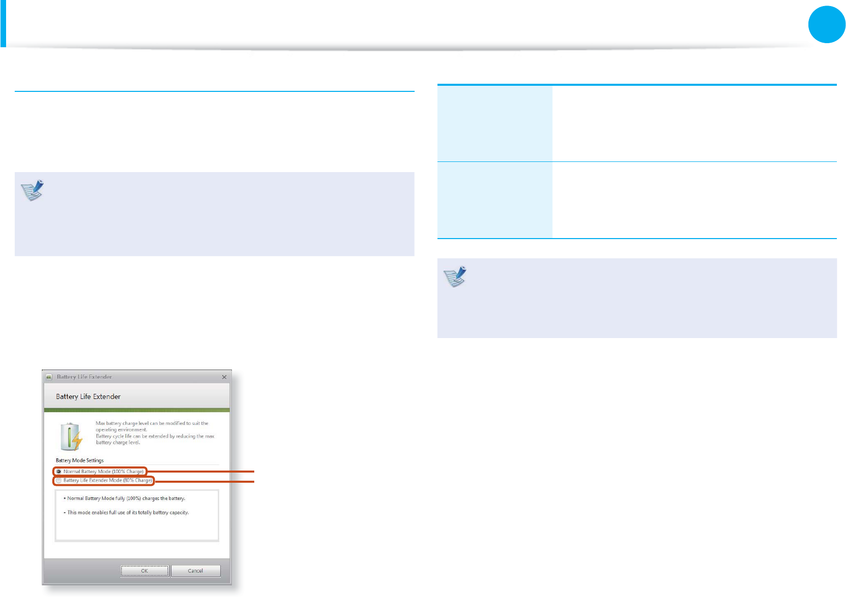
Extending the Battery Life (Optional)
The Battery Life Extender is a battery power management
program that enables extending the battery life. Users can change
the settings depending on their requirements.
The Battery Life Extender is optional and may not be t
supplied depending on the model.
The screen images and terms may diff er from actual t
product depending on the computer model.
1 Run Battery Life Extender.
2 When the following screen appears, select a mode and click
the OK button. You can use the battery in the selected mode.
Battery Normal Mode
Battery Life
Extension Mode
Battery Normal
Mode
This mode maintains 100% of the battery
charge when using the computer on AC power.
In this case, although the battery use time
increases, the battery life is reduced.
Battery Life
Extension Mode
This mode maintains 80% of the battery charge
when using the computer on AC power. In this
case, although the battery use time decreases,
the battery life is extended.
Press the F2 key when the Samsung logo appears in the
booting sequence to enter the BIOS Setup, select Advanced
> Battery Life Cycle Extension, and set it to Enable. Then
you can use the battery life cycle extension mode.
114
Chapter 3.
Settings and Upgrade
Battery
Using the Battery Calibration Function
When charging/discharging the battery repeatedly for a short time
only, the battery usage time may be reduced by the diff erence
between the actual battery charge and the remaining charge
display.
In this case, the actual battery charge and the remaining charge
display will be the same by discharging the battery completely
using the Battery Calibration function, and then recharging it
again.
The screen images and terms may diff er from actual product
depending on the computer model and driver version.
1 Disconnect the AC power adapter after turning off the
computer.
2 Restart your computer and press the F2 button when the
Samsung logo appears, to start the BIOS Setup.
3 Move to the Boot > Smart Battery Calibration item using
the direction keys and press <Enter>.
0WO.QEM =1HH?
6QWEJ2CF/QWUG ='PCDNGF?
+PVGTPCN.#0 ='PCDNGF?
2:'1241/ =&KUCDNGF?
5OCTV$CVVGT[%CNKDTCVKQP
4 Highlight Yes in the Battery Calibration Confi rmation
window and press <Enter>.
The Battery Calibration function is activated and the battery
is forcefully discharged. To stop the operation, press the
<Esc> button.
This operation requires 3~5 hours depending on the battery
capacity and the remaining battery charge.
115
Chapter 3.
Settings and Upgrade
Battery
Installing/Removing the Battery
1 Shutdown the system, close the LCD panel and place the
computer upside down on a flat surface.
2 ► For 12.5 inch models
Pull the battery latch outward, then remove the battery.
► For 14, 15.6 inch models
Lift the battery latch forward to remove the battery.
3 To install the battery again, slide the battery into the system.
The battery latches move inwards and fix the battery
automatically.
116
Chapter 3.
Settings and Upgrade
Using the Security Lock Port
You can connect a Kensington lock to the Security Lock port to
prevent your computer from being stolen when you have to use
the computer in a public place.
To use this feature, you have to purchase the Kensington lock
additionally. To use the Kensington lock, refer to the product
manual.
Tie the Kensington lock cable to a fixed object and install the
other end of the cable to the Security Lock port.

Chapter 4.
Backup / Restore
Samsung Recovery Solution (Optional) 118

118
Chapter 4.
Backup / Restore
Samsung Recovery Solution (Optional)
Samsung Recovery Solution is a program that enables restoring
or backing up the hard disk drive for when a problem occurs with
the computer.
If the computer fails to boot up, you can restore the computer by
pressing the F4 key in the booting screen.
Samsung Recovery Solution may not be provided or the t
version may diff er depending on the model. In addition,
some functions may not be provided or may diff er
depending on the version.
For more information on using Samsung Recovery
Solution, please refer to the online help of the program.
The screen images in this document may diff er from actual t
product.
If your computer does not have an internal ODD, you need t
an external ODD connected to your computer to use the
Backup Function or Restore Function using DVDs.
The System Software function may not be provided t
depending on the program version.
Samsung Recovery Solution Functions
Backup/Restore Functions
Backup Function
Backs up drive C or required folders and fi les.
Complete Backupt
Backs up drive C.
Data Backupt
Backs up important folders and fi les.
A problem
occurs
VIRUS
Restore Function
Restores major Windows fi les, drive C, or
folders and fi les to the previous state.
Basic Restoret
Restores only major Windows fi les in a short
time.
Complete Restoret
Restores drive C to the previous, normal
state.
Data Restoret
Restores important fi les or folders to the
previously backed up state.

119
Chapter 4.
Backup / Restore
System Software Functions
Samsung Recovery Solution provides system software so that
you can reinstall or copy the device drivers and system software
necessary for normal operations onto a separate storage device.
Restore Function
Not only can you use Samsung Recovery Solution when Windows
is running, but also when you are unable to boot up into Windows.
Let’s learn how to use Samsung Recovery Solution.
Optional functions such as Initial State Image, Initial Status Backup,
and Partitioning are only available in some models.
Partition Setup & Initial Status Backup
If you turn your computer on for the fi rst time, the Initial Status
Backup function is performed after registering Windows. This
function saves an image of the Initial Status of the C drive to a
secure location so that users can restore the computer to the
Initial Status using the Complete Restore function. An Initial Status
Backup is only performed once immediately after the computer is
purchased.
1 If you turn the power on for the fi rst time, the Register
Windows screen appears. If you register Windows according
to the instructions on the screen, the computer will be
restarted.
2 After the computer has been restarted, the Partition Setup
screen appears.
To resize the C and D drives, adjust the partition size using
the slide bar and the click Next.
The Partition Setup function is only available when the
computer is turned on for the fi rst time and will not
be available afterwards. Once you have completed the
partitioning, it cannot be resized. Partition the disk carefully.
3 The Initial Status Backup screen appears.
To continue the Initial Status Backup, click Restart Now. The
computer will restart.
4 The Initial Status Backup is performed to backup the initial
status of the C drive to a secure location. This backup image
is used for the Complete Restore function that restores your
computer to the initial status.
5 When the Initial Status Backup is complete, restart Windows.
Samsung Recovery Solution (Optional)
120
Chapter 4.
Backup / Restore
Restoring the computer
Restore is a function that enables restoring the computer to a
saved point when the computer was purchased or a user-saved
point.
The Restore function provides the Basic Restore and Complete
Restore options.
1 – When Windows is running:
Click Samsung Recovery Solution.
– When Windows does not start:
Turn the computer on and press the F4 key when the boot
screen (SAMSUNG logo) appears. After a moment, the
computer boots up in Restoration mode and the Samsung
Recovery Solution screen appears.
For computers supporting the touch screen function, the
touch screen function does not work during Restore Mode. In
this case, please use the touchpad or mouse.
2 If the initial menu screen appears, click Restore.
If you click Select by Symptom, the Select by Symptom
menu appears. If you select a symptom, a recommended
restoration option will blink. Click the restoration option to
continue.
Samsung Recovery Solution (Optional)
121
Chapter 4.
Backup / Restore
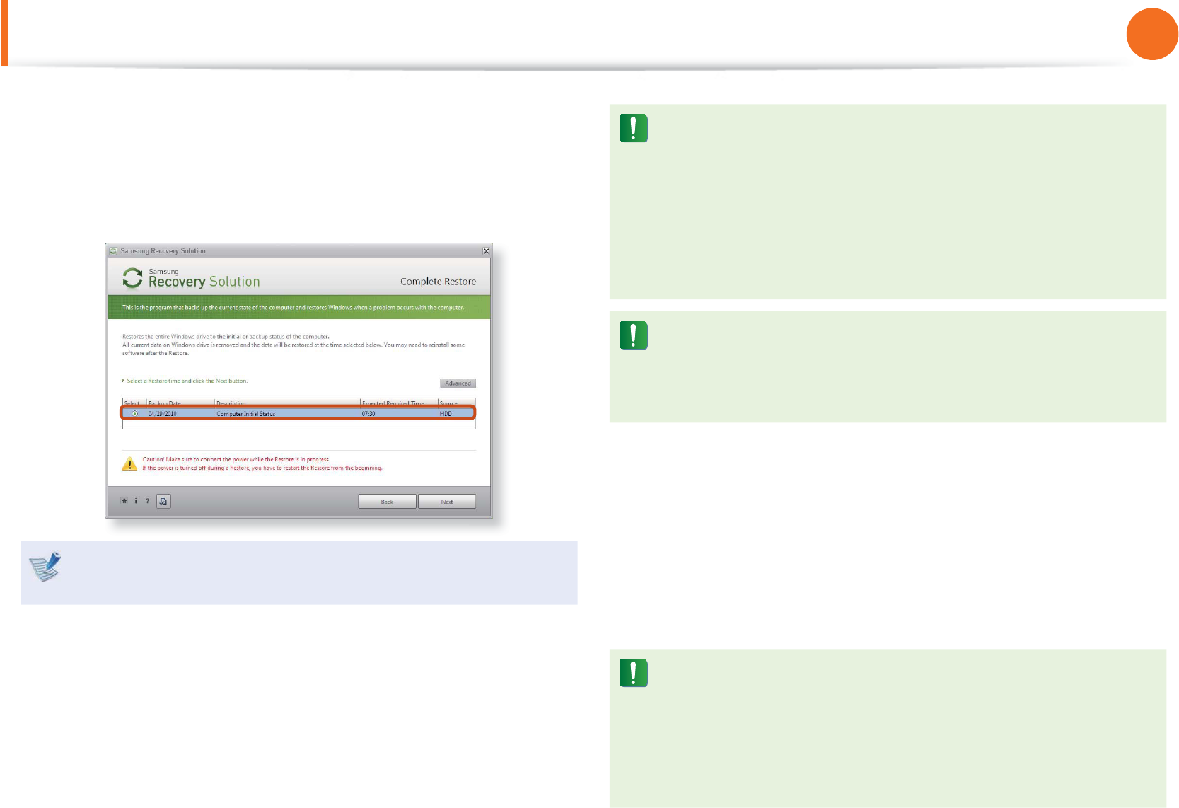
3 Select either Basic Restore or Complete Restore from the
Restore menu.
To restore the computer to the initial state, click Computer
Initial State and perform the restoration process according
to the instructions that appear on the screen.
Run Complete Restore if the computer does not work even
after Basic Restore has been completed.
In the Advanced menu, you can change the size of the hard
drive partitions (e.g. C: and D:).
Make sure to backup your data in advance, as all data will t
be deleted after the partition size is changed.
The t Advanced menu is only activated when the computer
boots up in the restoration area. (by pressing the F4 key
during the booting sequence.)
Since a Complete Restore deletes all user data as well
as additionally installed programs, please backup your
important data fi rst using the Data Backup function, before
running Complete Restore.
4 The computer boots up into restoration mode and the
restoration progress message appears. If you click OK, the
restoration begins. The restoration may take some time,
please wait for a moment.
5 When the ‘Restart the System’ message appears after the
restoration is complete, click OK to restart the system.
Make sure that the power cord is connected while the
restoration is in process. The fi rst time the computer boots
up after a Complete Restore has been performed, the speed
of the boot process may be slowed down due to the system
optimization process. At this time, do not shut the computer
down by force.
Samsung Recovery Solution (Optional)
122
Chapter 4.
Backup / Restore
Complete Backup/Restore
A Complete Backup saves the complete image of the C drive
onto another drive or DVD. A Complete Restore restores the
image fi le saved by the Complete Backup onto the C drive.
Complete Backup
If you run Complete Backup using a DVD, you can restore the
computer even when a problem occurs with the hard disk or
when the restoration area is removed.
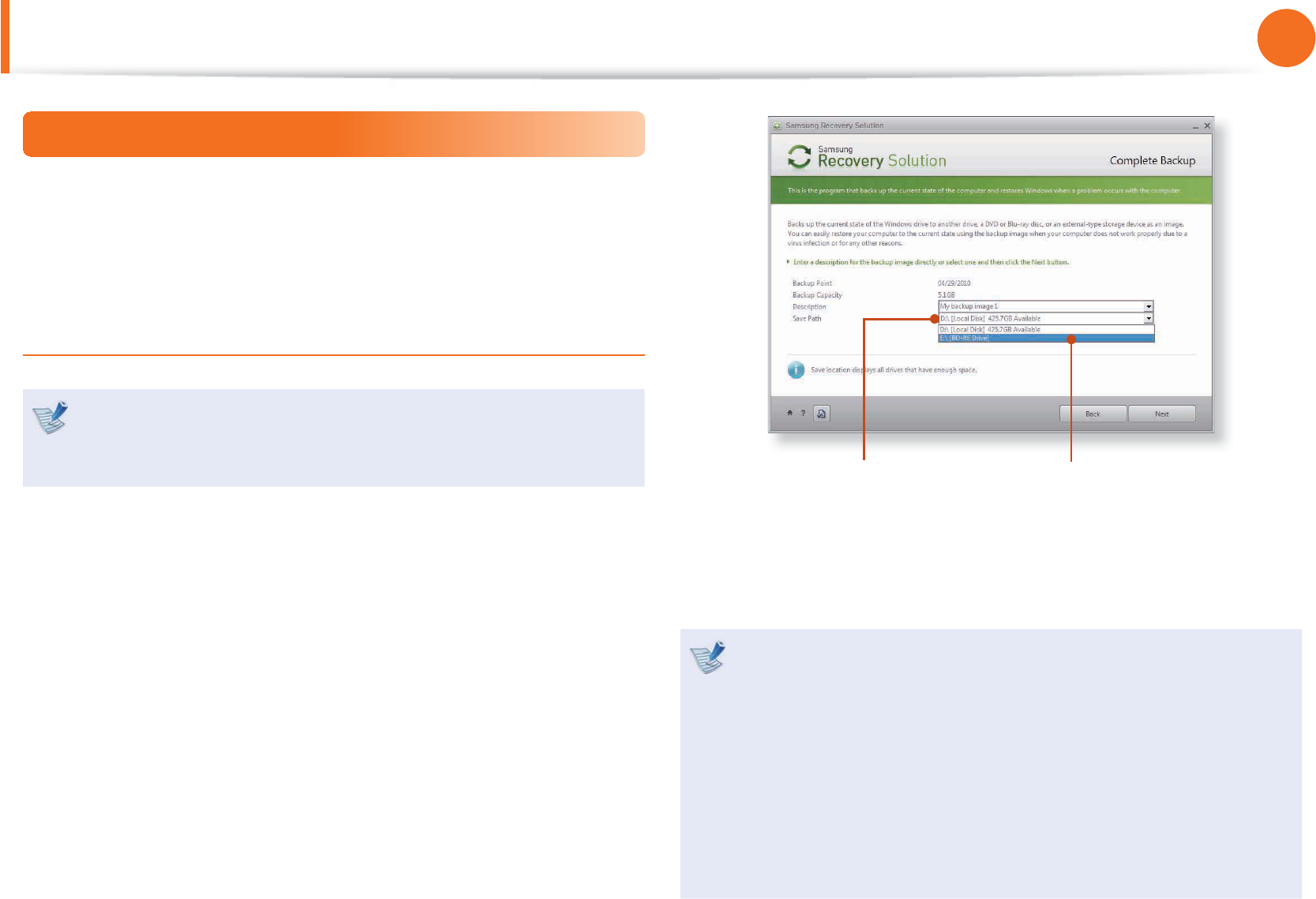
1 Click Backup in the start screen of the Samsung Recovery
Solution.
2 Enter a description of the current status of the computer and
click Next.
If a writable DVD drive is installed, you can specify the DVD as
the Save Path.
Select Drive D. Select the DVD drive.
3 When the option selection item appears, select an option
and click Next.
The LiveImaging and System Software Backup functions are
supported as options for the Complete Backup operation.
LiveImaging:t Performs the Complete Backup operation
while Windows is running. The backup operation using
LiveImaging may slow down if the hard disk drive is
accessed frequently by other applications.
System Software Backup: t This function backs up the
system software on to the DVD after the completion of the
Complete Backup operation.
Samsung Recovery Solution (Optional)
123
Chapter 4.
Backup / Restore
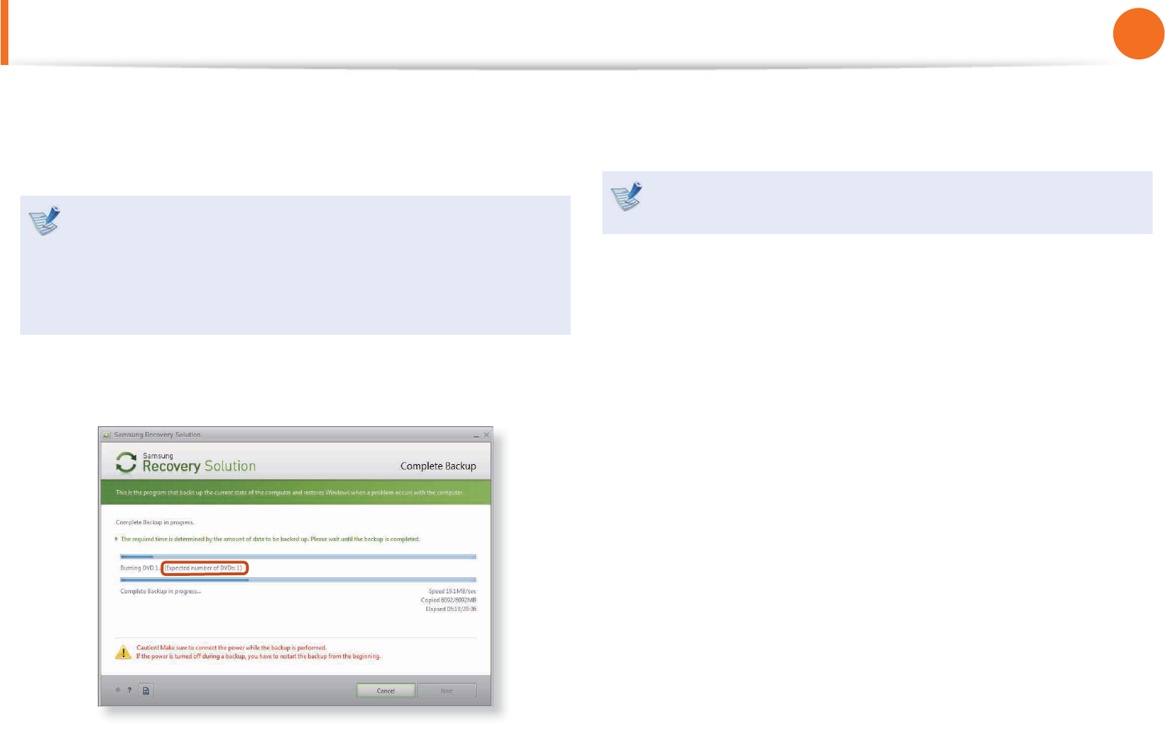
4 When the system restarts in Restoration Mode, the Complete
Backup operation begins. Continue with the backup by
following the instructions.
Samsung Recovery Solution supports the DVD+R, DVD-R, t
DVD+RW and DVD-RW formats.
If the LiveImaging option has been selected, the Complete t
Backup operation begins without the computer being
restarted.
5 Continue with the Complete Backup operation by following
the instructions.
6 When the ‘Restart the System’ message appears after the
backup is complete, click OK to restart the system.
If the LiveImaging option has been selected, the computer is
not restarted.
Samsung Recovery Solution (Optional)
124
Chapter 4.
Backup / Restore
Complete Restore
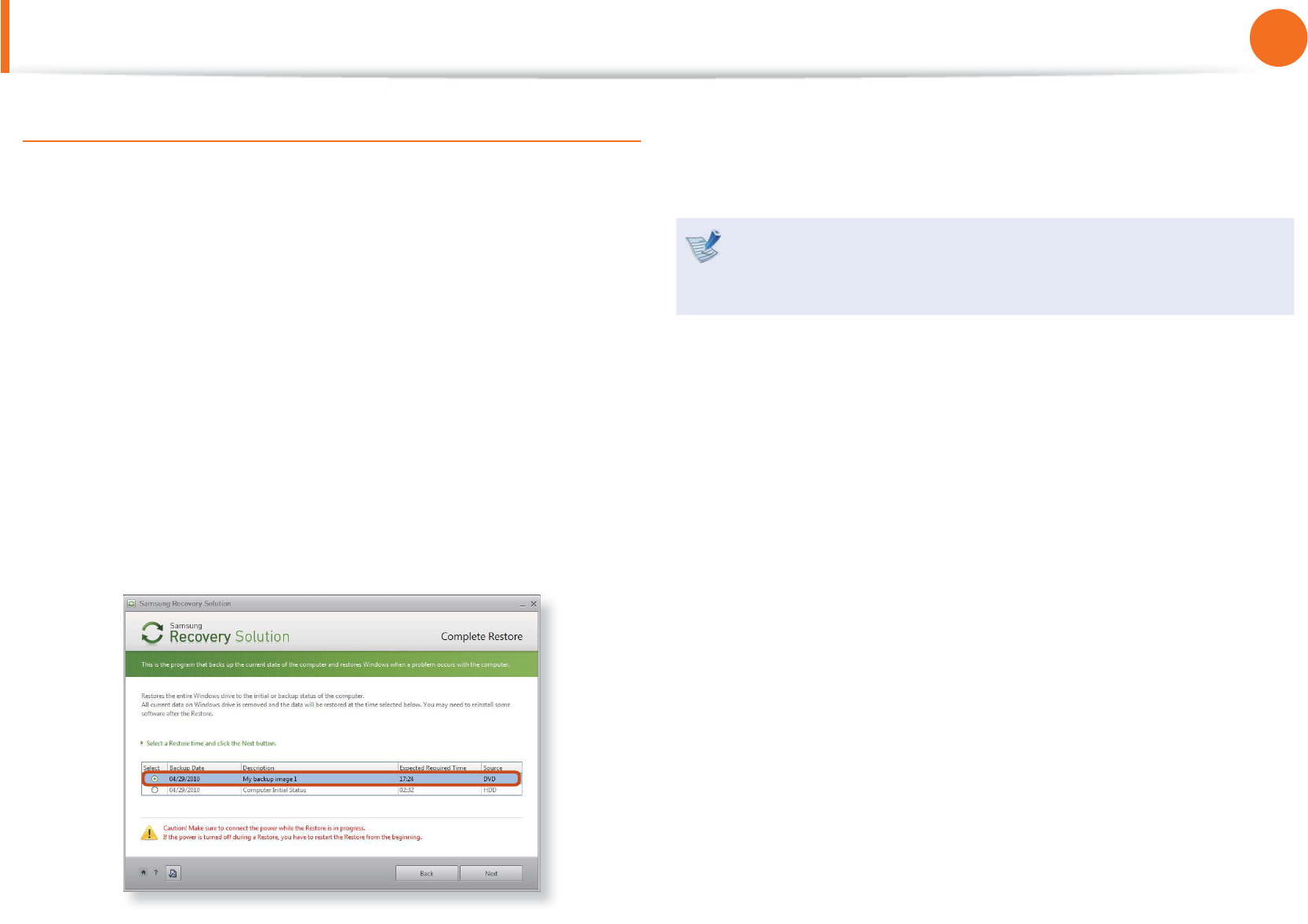
1 – When backing up onto DVD
Turn the computer on and insert the backup DVD into the
DVD drive.
If there are multiple backup DVDs, insert the fi rst DVD.
– When backing up to another drive
Proceed to Step 2.
2 When the Samsung Recovery Solution start screen appears,
click Restore and then click Complete Restore.
3 Select a Complete Backup restoration point in the
restoration point selection screen and click the Next button.
The system is restarted.
4 The restoration progress message appears after the computer
boots up in restoration mode. If you click OK, the restoration
begins.
If multiple DVDs have been used for a Complete Backup,
whenever burning a DVD is completed, the “Insert the next
DVD” message will appear.
5 When the ‘Restart the System’ message appears after the
restoration is complete, click OK to restart the system. The
Complete Restore has been completed.
Samsung Recovery Solution (Optional)
125
Chapter 4.
Backup / Restore
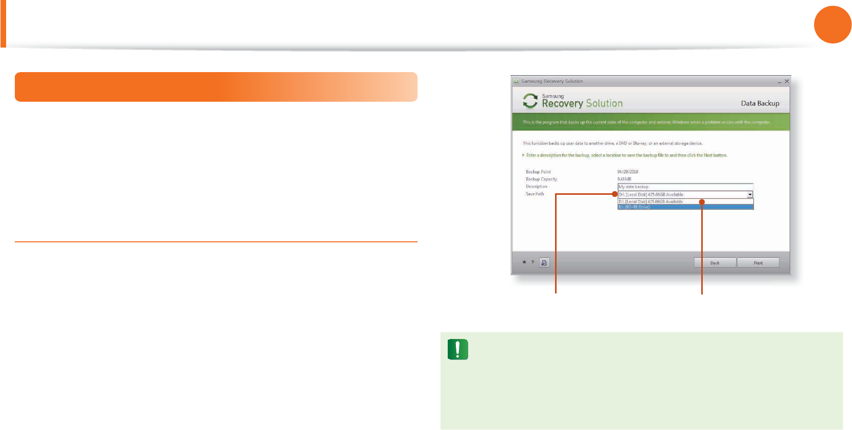
Data Backup/Restore
Data Backup enables you to save specifi c fi les or folders onto
another drive or DVD. Data Restore enables you to restore data
using the data saved by a Data Backup when data is lost. This
guide describes the Backup and Restore procedures on the basis
of backing up and restoring by using DVD.
Data Backup
1 When the Samsung Recovery Solution start screen appears,
click Backup and then click Data Backup.
2 In the data selection screen, select either Basic Selection or
Select from all, select a folder or fi le to be backed up, and
then click the Next button.
3 Enter a description for the backup in the Description fi eld
so that you can easily recognize it later and specify the Save
Path. If your computer has a DVD-Writer, you can specify the
DVD drive as the Save Path.
Select Drive D. Select the DVD drive.
If you have specifi ed a hard disk drive or a removable disk as
the Save Path, the SamsungRecovery\SamsungData folder
is created on the corresponding drive (e.g. D:\) and the data
is saved to the folder. Take care to not delete the folder by
mistake or on purpose.
4 If you click the Next button, the Data Backup begins. If you
have selected the DVD drive as the Save Path, the “Insert a
blank DVD” message appears. Insert a blank DVD and click
the OK button.
5 The “Backup is completed” message appears.
Samsung Recovery Solution (Optional)

126
Chapter 4.
Backup / Restore
Data Restore
1 – When backing up onto DVD
Turn the computer on and insert the backup DVD into the
DVD drive.
– When backing up to another drive
Proceed to Step 2.
2 When the initial menu screen appears, click Restore and then
click Data Restore.
3 Select a backup item to be restored in the backup list and
click the Next button.
4 Select a folder for the restoration and click the Next button.
Data Restore begins.
5 When Data Restore is completed, check if the data has been
restored to the specified folder.
Samsung Recovery Solution (Optional)
127
Chapter 4.
Backup / Restore
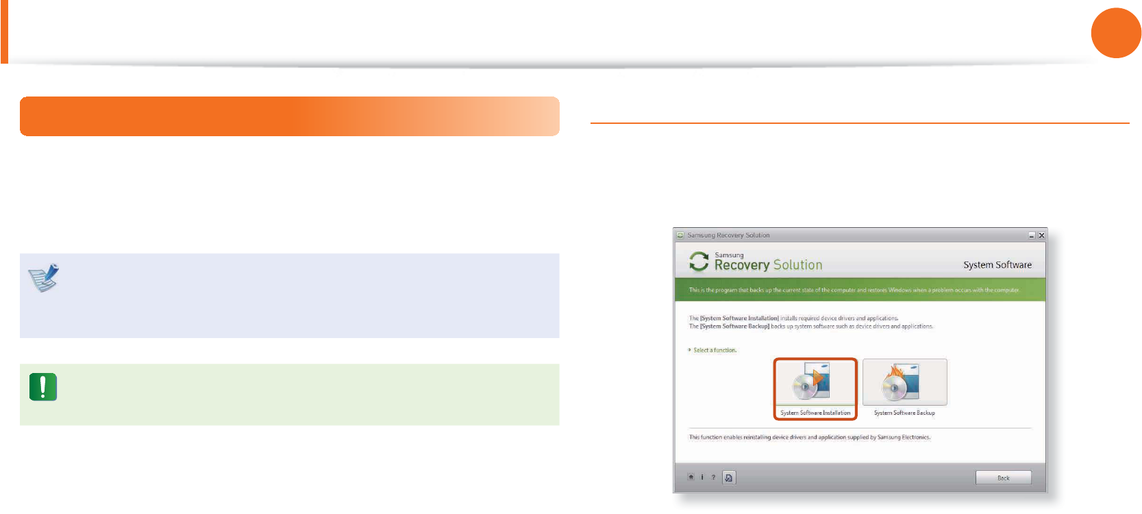
System Software Function
The System Software function is a function that enables you to
reinstall device drivers and System Software Programs or back up
those programs.
The system software function is supported by Samsung
Recovery Solution version 4 or later. Therefore, the
function may not be supported depending on the version.
The System Software Installation Function only works in
Microsoft Windows.
Installing System Software
1 When the initial menu screen appears, click System Software
> System Software Installation.
2 When the Samsung System Software screen appears, check
all the device drivers and application programs you want to
install and then click Install Now.
3 After the installation is complete, the computer will restart.
Samsung Recovery Solution (Optional)
128
Chapter 4.
Backup / Restore
Samsung Recovery Solution (Optional)
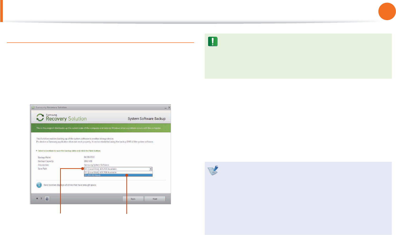
System Software Backup
1 When the initial menu screen appears, click System Software
> System Software Backup.
2 Specify the Save Path. If your computer has a DVD-Writer, you
can specify the DVD drive as the Save Path.
Select Drive D. Select the DVD drive.
If you have specifi ed a hard disk drive or a removable disk as
the Save Path, the SamsungSoftware folder is created on
the corresponding drive (e.g. D:\) and the system software
programs are saved to that folder. Take care to not delete the
folder.
3 If you click the Next button, the Software Backup begins.
If you have selected the DVD drive as the Save Path, the “Insert
a blank DVD” message appears. Insert a blank DVD and click
the OK button.
4 After the backup, the System Software Backup is
completed message appears.
If you want to install the System Software Programs backed t
up on the drive, run the SoftwareMediaXX.exe fi le in the
SystemSoftware folder.
When installing System Software Programs from the t
backed-up DVD, insert the DVD and follow the System
Software Installation directions.
To delete Samsung Recovery Solution, refer to the Help t
section of the program.

129
Chapter 4.
Backup / Restore
Recovery Solution Representation (Optional)
What is a Recovery Area?
Samsung computers have an additional partition to recover t
computers or save backup files.
(Only for models with the Samsung Recovery Solution.)
This partition is called a Recovery Area and it includes a recovery
image that comprises of the OS and application programs.
You can either double-click the Samsung Recovery Solution icon t
on the desktop or press F4 while booting the computer to enter
the Recovery Area. Then you can back up the present computer
state or recover the computer from backed up images.
For deleting the Recovery Area, you need to use an additional t
Recovery Area Removal Tool. After deleting the recovery area,
you can use the newly created partition for other uses, such as
for saving personal data. Be careful that once the recovery area is
deleted, the Samsung Recovery Solutions will not work anymore.
The capacity representation of the hard disk drive(HDD)
in Windows is different from the product specifications.
The capacity of the storage device (HDD) of the manufacturer is t
calculated assuming that 1KB=1,000 Bytes. However, the operating
system (Windows) calculates the storage device capacity assuming
that 1KB=1,024 Bytes, and therefore the capacity representation of
the HDD in Windows is smaller than the actual capacity.
This is due to the difference in capacity calculation and does
not mean the installed HDD is different from the product
specifications.
The capacity representation in Windows may be smaller than the t
actual capacity because some programs occupy a certain area of
the HDD outside of Windows.
For models with Samsung Recovery Solution, the HDD capacity t
representation in Windows may be smaller than the actual
capacity because Samsung Recovery Solution uses a hidden area
of about 5~20GB of the HDD to save the recovery image, and
that hidden area is not counted towards the total size available to
Windows.
The size of Samsung Recovery Solution varies by models because
of the different size of applied programs.
Samsung Recovery Solution (Optional)

Chapter 5.
Appendix
Important Safety Information 131
Replacement Parts and Accessories 133
Regulatory Compliance Statements 135
WEEE Symbol Information 150
Product Specifi cations 151
Glossary 153
Index 157

131
Chapter 5.
Appendix
Safety Instructions
Your system is designed and tested to meet the latest standards
for safety of information technology equipment. However, to
ensure safe use of this product, it is important that the safety
instructions marked on the product and in the documentation are
followed.
Always follow these instructions to help guard against
personal injury and damage to your system.
Setting Up your System
Read and follow all instructions marked on the product and in t
the documentation before you operate your system. Retain all
safety and operating instructions for future use.
Do not use this product near water or a heat source such as a t
radiator.
Set up the system on a stable work surface.t
The product should be operated only with the type of power t
source indicated on the rating label.
Ensure that the electrical outlet you are using to power your t
equipment is easily accessible in case of fi re or short circuit.
If your computer has a voltage selector switch, make sure that t
the switch is in the proper position for your area.
Openings in the computer case are provided for ventilation. t
Do not block or cover these openings. Make sure you provide
adequate space, at least 6 inches (15 cm), around the system
for ventilation when you set up your work area. Never insert
objects of any kind into the computer ventilation openings.
Ensure that the fan vents on the bottom of the casing are clear t
at all times. Do not place the computer on a soft surface, doing
so will block the bottom vents.
If you use an extension cord with this system, make sure that t
the total power rating on the products plugged into the
extension cord does not exceed the extension cord power
rating.
For Notebooks with glossy display bezels the user should t
consider the placement of the Notebook as the bezel may
cause disturbing refl ections from surrounding light and bright
surfaces.
Important Safety Information

132
Chapter 5.
Appendix
Care During Use
Do not walk on the power cord or allow anything to rest on it.t
Do not spill anything on the system. The best way to avoid t
spills is to not eat or drink near your system.
Some products have a replaceable CMOS battery on the t
system board. There is a danger of explosion if the CMOS
battery is replaced incorrectly. Replace the battery with the
same or equivalent type recommended by the manufacturer.
Dispose of batteries according to the manufacturers
instructions. If the CMOS battery requires replacement insure
that a qualified technician performs the task.
When the computer is turned off, a small amount of electrical t
current still flows through the computer.
To avoid electrical shock, always unplug all power cables,
remove the battery and modem cables from the wall outlets
before cleaning the system.
Unplug the system from the wall outlet and refer servicing to t
qualified personnel if:
– The power cord or plug is damaged.
– Liquid has been spilled into the system.
– The system does not operate properly when the operating
instructions are followed.
– The system was dropped or the casing is damaged.
– The system performance changes.
The Instruction On Safety Operation of NotePC
1.When installing and operating devices please refer to safety
requirements in the user guide.
2.Devices can be used only with the equipment specified in the
technical specifications of the devices.
3. If any smell of burning or smoke is detected from the computer
the unit should be switched off and battery removed. The unit
should be checked by a qualified technician before reuse.
4.Service and repair of devices should be carried out by
authorized service centers.
5.Do not allow your portable computer to operate with the base
resting directly on exposed skin for extended periods of time.
The surface temperature of the base will rise during normal
operation (particularly when AC Power is present). Allowing
sustained contact with exposed skin can cause discomfort or
eventually a burn.
Important Safety Information

133
Chapter 5.
Appendix
Replacement Parts and Accessories
Use only replacement parts and accessories recommended by
manufacturer.
To reduce the risk of fi re, use only No. 26 AWG or larger
telecommunications line cord.
Do not use this product in areas classifi ed as hazardous.
Such areas include patient care areas of medical and dental
facilities, oxygen rich environments, or industrial areas.
Battery Disposal
Do not put rechargeable batteries or products powered by
non-removable rechargeable batteries in the garbage.
Contact the Samsung Helpline for information on how to dispose
of batteries that you cannot use or recharge any longer.
Follow all local regulations when disposing of old batteries.
THERE IS A RISK OF EXPLOSION IF BATTERY IS REPLACED BY
AN INCORRECT TYPE.
DISPOSE OF USED BATTERIES ACCORDING TO THE
INSTRUCTIONS.
Laser Safety
All systems equipped with CD or DVD drives comply with the
appropriate safety standards, including IEC 60825-1. The laser
devices in these components are classifi ed as “Class 1 Laser
Products” under a US Department of Health and Human Services
(DHHS) Radiation Performance Standard. Should the unit ever
need servicing, contact an authorized service location.
Laser Safety Note:t
Use of controls or adjustments or performance of
procedures other than those specifi ed in this manual
may result in hazardous radiation exposure. To prevent
exposure to laser beams, do not try to open the enclosure
of a CD or DVD drive.
Class 1M laser radiation when operating part is open.t
Do not view directly with optical instruments.
Class 3B invisible laser radiation when open.t
Avoid exposure to the beam.

134
Chapter 5.
Appendix
Replacement Parts and Accessories
Connecting and Disconnecting the AC adapter
The socket-outlet should be installed near the equipment and
should be easily accessible.
Do not unplug the power cord by only pulling the cable.
Power Cord Requirements
The power cord set (wall plug, cable and AC adapter plug) you
received with your computer meets the requirements for use in
the country where you purchased your equipment.
Power cord sets for use in other countries must meet the
requirements of the country where you use the computer. For
more information on power cord set requirements, contact your
authorized dealer, reseller, or service provider.
General Requirements
The requirements listed below are applicable to all countries:
All power cord sets must be approved by an acceptable t
accredited agency responsible for evaluation in the country
where the power cord set will be used.
The power cord set must have a minimum current capacity t
of 7 A and a nominal voltage rating of 125 or 250 volts AC, as
required by each country’s power system. (USA ONLY)
The appliance coupler must meet the mechanical configuration t
of an EN 60 320/IEC 320 Standard Sheet C7 (or C5) connector,
for mating with appliance inlet on the computer.

135
Chapter 5.
Appendix
Regulatory Compliance Statements
Wireless Guidance
(If fitted with 2.4G band or 5G band)
Low power, Radio LAN type devices (radio frequency (RF) wireless
communication devices), operating in the 2.4GHz/5GHz Band, may
be present (embedded) in your notebook system. The following
section is a general overview of considerations while operating a
wireless device.
Additional limitations, cautions, and concerns for specific countries
are listed in the specific country sections (or country group
sections). The wireless devices in your system are only qualified for
use in the countries identified by the Radio Approval Marks on the
system rating label. If the country you will be using the wireless
device in, is not listed, please contact your local Radio Approval
agency for requirements. Wireless devices are closely regulated
and use may not be allowed.
The RF field strength of the wireless device or devices that may
be embedded in your notebook are well below all international
RF exposure limits as known at this time. Because the wireless
devices (which may be embedded into your notebook) emit less
energy than is allowed in radio frequency safety standards and
recommendations, manufacturer believes these devices are safe
for use. Regardless of the power levels, care should be taken to
minimize human contact during normal operation.
As a general guideline, a separation of 20 cm (8 inches) between
the wireless device and the body, for use of a wireless device near
the body (this does not include extremities) is typical. This device
should be used more than 20 cm (8 inches) from the body when
wireless devices are on and transmitting.
Some circumstances require restrictions on wireless devices.
Examples of common restrictions are listed on the next page:
Radio frequency wireless communication can interfere t
with equipment on commercial aircraft. Current aviation
regulations require wireless devices to be turned off while
traveling in an airplane.
802.11ABGN (also known as wireless Ethernet or Wifi) and
Bluetooth communication devices are examples of devices
that provide wireless communication.
In environments where the risk of interference to other t
devices or services is harmful or perceived as harmful,
the option to use a wireless device may be restricted or
eliminated. Airports, Hospitals, and Oxygen or flammable
gas laden atmospheres are limited examples where use
of wireless devices may be restricted or eliminated. When
in environments where you are uncertain of the sanction
to use wireless devices, ask the applicable authority for
authorization prior to use or turning on the wireless device.

136
Chapter 5.
Appendix
Regulatory Compliance Statements
Every country has different restrictions on the use of t
wireless devices. Since your system is equipped with
a wireless device, when traveling between countries
with your system, check with the local Radio Approval
authorities prior to any move or trip for any restrictions on
the use of a wireless device in the destination country.
If your system came equipped with an internal embedded t
wireless device, do not operate the wireless device unless
all covers and shields are in place and the system is fully
assembled.
Wireless devices are not user serviceable. Do not modify t
them in any way. Modification to a wireless device will void
the authorization to use it. Please contact manufacturer for
service.
Only use drivers approved for the country in which t
the device will be used. See the manufacturer System
Restoration Kit, or contact manufacturer Technical Support
for additional information.
United States of America
USA and Canada Safety Requirements and Notices
Do not touch or move antenna while the unit is transmitting or
receiving.
Do not hold any component containing the radio such that the
antenna is very close or touching any exposed parts of the body,
especially the face or eyes, while transmitting.
Do not operate the radio or attempt to transmit data unless the
antenna is connected; if not, the radio may be damaged.
Use in specific environments:
The use of wireless devices in hazardous locations is limited by the
constraints posed by the safety directors of such environments.
The use of wireless devices on airplanes is governed by the Federal
Aviation Administration (FAA).
The use of wireless devices in hospitals is restricted to the limits
set forth by each hospital.
Explosive Device Proximity Warning
Do not operate a portable transmitter (such as a wireless
network device) near unshielded blasting caps or in an
explosive environment unless the device has been modified
to be qualified for such use.

137
Chapter 5.
Appendix
Use On Aircraft Caution
Regulations of the FCC and FAA prohibit airborne operation
of radio-frequency wireless devices because their signals
could interfere with critical aircraft instruments.
Other Wireless Devices
Safety Notices for Other Devices in the Wireless Network: Refer
to the documentation supplied with wireless Ethernet adapters or
other devices in the wireless network.
The Part 15 radio device operates on a non-interference basis
with other devices operating at this frequency. Any changes
or modification to said product not expressly approved by
Intel could void the user’s authority to operate this device.
Unintentional Emitter per FCC Part 15
This device complies with Part 15 of the FCC Rules. Operation is
subject to the following two conditions:(1) this device may not
cause harmful interference, and (2) this device must accept any
interference received, including interference that may cause
undesired operation.
This equipment has been tested and found to comply
with the limits for a Class B digital device pursuant to Part
15 of the FCC Rules. These limits are designed to provide
reasonable protection against harmful interference in a
residential installation. This equipment generates, uses,
and can radiate radio frequency energy. If not installed
and used in accordance with the instructions, it may cause
harmful interference. If this equipment does cause harmful
interference to radio or television reception, which can be
determined by turning the equipment off and on, the user is
encouraged to try to correct the interference by one or more
of the following measures:
Reorient or relocate the receiving antenna.t
Increase the separation between the equipment and t
receiver.
Connect the equipment into an outlet on a circuit different t
from that to which the receiver is connected.
Consult the dealer or an experienced radio/TV technician t
for help.
Regulatory Compliance Statements

138
Chapter 5.
Appendix
If necessary, the user should consult the dealer or an experienced
radio/television technician for additional suggestions. The user
may find the following booklet helpful: “Something About
Interference.”
This is available at FCC local regional offices. Our company is not
responsible for any radio or television interference caused by
unauthorized modifications of this equipment or the substitution
or attachment of connecting cables and equipment other than
those specified by our company. The correction will be the
responsibility of the user. Use only shielded data cables with this
system.
Intentional emitter per FCC Part 15
(If fitted with 2.4G band or 5G band)
Low power, Radio LAN type devices (radio frequency (RF) wireless
communication devices), operating in the 2.4GHz/5GHz Band, may
be present (embedded) in your notebook system. This section is
only applicable if these devices are present. Refer to the system
label to verify the presence of wireless devices.
Wireless devices that may be in your system are only qualified for
use in the United States of America if an FCC ID number is on the
system label.
This device is restricted to indoor use due to its operation in the
5.15 to 5.25 GHz frequency range. FCC requires this product to be
used indoors for the frequency range 5.15 to 5.25 GHz to reduce
the potential for harmful interference to co-channel Mobile
Satellite systems. High power radars are allocated as primary users
of the 5.25 to 5.35 GHz and 5.65 to 5.85 GHz bands. These radar
stations can cause interference with and /or damage this device.
The FCC has set a general guideline of 20 cm (8 inches) separation
between the device and the body, for use of a wireless device
near the body (this does not include extremities). This device
should be used more than 20 cm (8 inches) from the body when
wireless devices are on. The power output of the wireless device (or
devices), which may be embedded in your notebook, is well below
the RF exposure limits as set by the FCC.
This transmitter must not be collocated or operate in conjunction
with any other antenna or transmitter except the installed
Bluetooth transmitter.
Operation of this device is subject to the following two conditions:
(1) This device may not cause harmful interference, and (2)
this device must accept any interference received, including
interference that may cause undesired operation of the device.
Regulatory Compliance Statements

139
Chapter 5.
Appendix
Wireless devices are not user serviceable. Do not modify
them in any way.
Modification to a wireless device will void the authorization
to use it. Contact manufacturer for service.
FCC Statement for Wireless LAN use:
While installing and operating this transmitter and antenna
combination the radio frequency exposure limit of 1mW/cm2
may be exceeded at distances close to the antenna installed.
Therefore, the user must maintain a minimum distance of
20cm from the antenna at all times.
This device can not be colocated with another transmitter
and transmitting antenna.
FCC Part 68 (If fitted with a modem device.)
This equipment compiles with part of the FCC rules. On the
back of this equipment is a label that contains, among other
information, the FCC registration number and ringer equivalence
number (REN) for this equipment. If requested, this information
must be provided to the telephone company.
This equipment uses the following USOC jacks : RJ11C
An FCC compliant telephone cord and modular plug is provided
with this equipment. This equipment is designed to be connected
to the telephone network or promises wiring using a compatible
modular jack which is Part 68 compliant. See Installation
Instructions for details.
Regulatory Compliance Statements

140
Chapter 5.
Appendix
The REN is used to determine the quantity of devices which may
be connected to telephone line. Excessive RENs on the telephone
line may result in the devices not ringing in response to an
incoming call. In most, but not all areas, the sum of RENs should
not exceed five (5.0). To be certain of the number of devices that
may be connected to a line, as determined by total RENs, contact
the local telephone company to determine the maximum REN for
the calling area.
If the terminal equipment causes harm to the telephone network,
the Telephone Company will notify you in advance that temporary
discontinuance of service may be required. But if advance notice
is not practical, the telephone company will notify the customer
as soon as possible. Also, you will be advised of your right to file a
complaint with the FCC if you believe it is necessary.
The telephone company may make changes in its facilities,
equipment, operations, or procedures that could affect the
operation of the equipment. If this happens, the telephone
company will provide advanced notice in order for you to make
necessary modifications to maintain uninterrupted service.
If trouble is experienced with this equipment (Modem) for repair
or warranty information, please contact your local distributor.
If the equipment is causing harm to the telephone network,
the telephone company may request that you disconnect the
equipment until the problem is resolved.
The user must use the accessories and cables supplied by the
manufacturer to get optimum performance from the product.
No repairs may be done by the customer.
This equipment cannot be used on public coin phone service
provided by the telephone company. Connection to party line
service is subject to state tariffs.
The Telephone Consumer Protection Act of 1991 makes it
unlawful for any person to use a computer or other electronic
device, including fax machines, to send any message unless such
message clearly contains in a margin at the top or bottom of
each transmitted page or on the first page of the transmission,
the date and time it is sent and an identification of the business
or other entity, or other individual sending the message and the
telephone number of the sending machine or such business, other
entity, or individual. (The telephone number provided may not
be any number for which charges exceed local or long-distance
transmission charges.)
In order to program this information into your fax machine, refer
to your communications software user manual.
Regulatory Compliance Statements

141
Chapter 5.
Appendix
Canada
Unintentional Emitter per ICES-003
This digital apparatus does not exceed the Class B limits for radio
noise emissions from digital apparatus as set out in the radio
interference regulations of Industry Canada.
Le présent appareil numérique n’émet pas de bruits
radioélectriques dépassant les limitesapplicables aux appareils
numériques de Classe B prescrites dans le règlement sur le
brouillage radioélectrique édicté par Industrie Canada.
Intentional Emitter per RSS 210
This device complies with RSS 210 of Industry Canada. Operation
is subject to the following two onditions: (1) this device may
not cause interference, and (2) this device must accept any
interference, including interference that may cause undesired
operation of this device.”
L‘utilisation de ce dispositif est autorisée seulement aux conditions
suivantes : (1) il ne doit pas produire de brouillage et (2) l’
utilisateur du dispositif doit étre prêt à accepter tout brouillage
radioélectrique reçu, même si ce brouillage est susceptible de
compromettre le fonctionnement du dispositif.
The term “IC” before the equipment certification number only
signifies that the Industry Canada technical specifications were
met. To reduce potential radio interference to other users, the
antenna type and its gain should be so chosen that the equivalent
isotropically radiated power (EIRP) is not more than that required
for successful communication. To prevent radio interference
to the licensed service, this device is intended to be operated
indoors and away from windows to provide maximum shielding.
Equipment (or its transmit antenna) that is installed outdoors is
subject to licensing.
Pour empecher que cet appareil cause du brouillage au service
faisant l’objet d’une licence, il doit etre utilize a l’interieur et devrait
etre place loin des fenetres afin de Fournier un ecram de blindage
maximal. Si le matriel (ou son antenne d’emission) est installe a
l’exterieur, il doit faire l’objet d’une licence.
(If fitted with 2.4G band or 5G band)
Low power, Radio LAN type devices (radio frequency (RF) wireless
communication devices), operating in the 2.4GHz/5GHz Band, may
be present (embedded) in your notebook system. This section is
only applicable if these devices are present. Refer to the system
label to verify the presence of wireless devices.
Wireless devices that may be in your system are only qualified for
use in Canada if an Industry Canada ID number is on the system
label.
Regulatory Compliance Statements

142
Chapter 5.
Appendix
When using IEEE 802.11a wireless LAN, this product is restricted to
indoor use due to its operation in the 5.15- to 5.25-GHz frequency
range. Industry Canada requires this product to be used indoors
for the frequency range of 5.15 GHz to 5.25 GHz to reduce the
potential for harmful interference to co-channel mobile satellite
systems. High power radar is allocated as the primary user of the
5.25- to 5.35-GHz and 5.65 to 5.85-GHz bands. These radar stations
can cause interference with and/or damage to this device.
The maximum allowed antenna gain for use with this device
is 6dBi in order to comply with the E.I.R.P limit for the 5.25- to
5.35 and 5.725 to 5.85 GHz frequency range in point-to-point
operation.
As a general guideline, a separation of 20 cm (8 inches) between
the wireless device and the body, for use of a wireless device near
the body (this does not include extremities) is typical. This device
should be used more than 20 cm (8 inches) from the body when
wireless devices are on.
The power output of the wireless device (or devices), which may
be embedded in your notebook, is well below the RF exposure
limits as set by Industry Canada.
This transmitter must not be collocated or operate in conjunction
with any other antenna or transmitter except the installed
Bluetooth transmitter.
Operation of this device is subject to the following two conditions:
(1) This device may not cause harmful interference, and (2)
this device must accept any interference received, including
interference that may cause undesired operation of the device.
To prevent radio interference to licensed service, this device
is intended to be operated indoors and away from windows
to provide maximum shielding. Equipment (or its transmit
antenna) that is installed outdoors is subject to licensing.
Wireless devices are not user serviceable. Do not modify
them in any way. Modification to a wireless device will void
the authorization to use it. Contact manufacturer for service.
Regulatory Compliance Statements

143
Chapter 5.
Appendix
Telecommunications per DOC notice
(for products fitted with an IC-compliant modem)
The Industry Canada label identifies certified equipment.
This certification means that the equipment meets certain
telecommunications network protective, operation, and safety
requirements. The Department does not guarantee the equipment
will operate to the users’ satisfaction.
Before installing this equipment, users should make sure that
it is permissible to be connected to the facilities of the local
telecommunications company. The equipment must also be
installed using an acceptable method of connection. In some
cases, the inside wiring associated with a single-line individual
service may be extended by means of a certified connector
assembly. The customer should be aware that compliance with
the above conditions may not prevent degradation of service in
some situations.
Repairs to certified equipment should be made by an authorized
Canadian maintenance facility designated by the supplier. Any
repairs or alterations made by the user to this equipment, or
equipment malfunctions, may give the telecommunications
company cause to request the user to disconnect the equipment.
Users should make sure, for their own protection, that the
electrical ground connections of the power utility, telephone lines,
and internal metallic water pipe system, if present, are connected
together. This precaution may be particularly important in rural
areas.
To avoid electrical shock or equipment malfunction do not
attempt to make electrical ground connections by yourself.
Contact the appropriate inspection authority or an electrician,
as appropriate.
The Ringer Equivalence Number (REN) assigned to each
terminal device provides an indication of the maximum number
of terminals allowed to be connected to a telephone interface.
The termination on an interface may consist of any combination of
devices subject only to the requirement that the sum of the Ringer
Equivalence Numbers of all the devices does not exceed 5.
Regulatory Compliance Statements

144
Chapter 5.
Appendix
Brazil
Este equipamento opera em caráter secundário, isto é, não
tem direito a proteção contra interferência prejudicial, mesmo
de estações do mesmo tipo, e não pode causar interferência a
sistemas operando em caráter primário.
European Union
European Union CE Marking and Compliance Notices
Products intended for sale within the European Union are marked
with the Conformité Européene (CE) Marking, which indicates
compliance with the applicable Directives and European standards
and amendments identified below. This equipment also carries
the Class 2 identifier.
The following information is only applicable to systems labeled
with the CE mark .
European Directives
This Information Technology Equipment has been tested and
found to comply with the following European directives:
EMC Directive 2004/108/ECt
Low Voltage Directive 2006/95/ECt
R&TTE Directive 1999/5/ECt
Manufacturer Information
Samsung Electronics Co., Ltd.
416, Maetan-3Dong, Yeongtong-Gu, Suwon-City, Gyeonggi-Do,
443-742, Korea
Samsung Electronics Suzhou Computer Co., Ltd.
No. 198, Fangzhou Road, Suzhou Industrial Park, Jiangsu Province,
215021, China
Tel: +86-512-6253-8988
For the web or the phone number of Samsung Service Centre, see
the Warranty or contact the retailer where you purchased your
product.
Regulatory Compliance Statements
145
Chapter 5.
Appendix
European Radio Approval Information
(for products fi tted with EU-approved radio devices)
This Product is a Notebook computer; low power, Radio LAN type
devices (radio frequency (RF) wireless communication devices),
operating in the 2.4GHz/5GHz band, may be present (embedded)
in your notebook system which is intended for home or offi ce use.
This section is only applicable if these devices are present. Refer to
the system label to verify the presence of wireless devices.
Wireless devices that may be in your system are only qualifi ed for
use in the European Union or associated areas if a CE mark
with a Notifi ed Body Registration Number and the Alert Symbol is
on the system label.
The power output of the wireless device or devices that may be
embedded in you notebook is well below the RF exposure limits
as set by the European Commission through the R&TTE directive.
The low band 5.15 - 5.35 GHz is for indoor use only.
See 802.11b and 802.11g restrictions for specifi c countries
or regions within countries under the heading “European
Economic Area Restrictions” below.
EU R&TTE Compliance Statements
Česky
[Czech]
Samsung tímto prohlašuje, že tento Notebook
PC je ve shodě se základními požadavky a
dalšími příslušnými ustanoveními směrnice
1999/5/ES.
Dansk
[Danish]
Undertegnede Samsung erklærer herved,
at følgende udstyr Notebook PC overholder
de væsentlige krav og øvrige relevante krav i
direktiv 1999/5/EF.
Deutsch
[German]
Hiermit erklärt Samsung, dass sich das Gerät
Notebook PC in Übereinstimmung mit den
grundlegenden Anforderungen und den
übrigen einschlägigen Bestimmungen der
Richtlinie 1999/5/EG befi ndet.
Eesti
[Estonian]
Käesolevaga kinnitab Samsung seadme
Notebook PC vastavust direktiivi 1999/5/
EÜ põhinõuetele ja nimetatud direktiivist
tulenevatele teistele asjakohastele sätetele.
English
Hereby, Samsung, declares that this Notebook
PC is in compliance with the essential
requirements and other relevant provisions of
Directive 1999/5/EC.
Español
[Spanish]
Por medio de la presente Samsung declara
que el Notebook PC cumple con los requisitos
esenciales y cualesquiera otras disposiciones
aplicables o exigibles de la Directiva 1999/5/CE.
Regulatory Compliance Statements
146
Chapter 5.
Appendix
Ελληνική
[Greek]
ΜΕ ΤΗΝ ΠΑΡΟΥΣΑ Samsung ΔΗΛΩΝΕΙ ΟΤΙ
Notebook PC ΣΥΜΜΟΡΦΩΝΕΤΑΙ ΠΡΟΣ ΤΙΣ
ΟΥΣΙΩΔΕΙΣ ΑΠΑΙΤΗΣΕΙΣ ΚΑΙ ΤΙΣ ΛΟΙΠΕΣ
ΣΧΕΤΙΚΕΣ ΔΙΑΤΑΞΕΙΣ ΤΗΣ ΟΔΗΓΙΑΣ 1999/5/ΕΚ.
Français
[French]
Par la présente Samsung déclare que l’appareil
Notebook PC est conforme aux exigences
essentielles et aux autres dispositions
pertinentes de la directive 1999/5/CE.
Italiano
[Italian]
Con la presente Samsung dichiara che questo
Notebook PC è conforme ai requisiti essenziali
ed alle altre disposizioni pertinenti stabilite
dalla direttiva 1999/5/CE.
Latviski
[Latvian]
Ar šo Samsung deklarē, ka Notebook PC atbilst
Direktīvas 1999/5/EK būtiskajām prasībām un
citiem ar to saistītajiem noteikumiem.
Lietuvių
[Lithuanian]
Šiuo Samsung deklaruoja, kad šis Notebook PC
atitinka esminius reikalavimus ir kitas 1999/5/
EB Direktyvos nuostatas.
Nederlands
[Dutch]
Hierbij verklaart Samsung dat het toestel
Notebook PC in overeenstemming is met
de essentiële eisen en de andere relevante
bepalingen van richtlijn 1999/5/EG.
Malti
[Maltese]
Hawnhekk, Samsung, jiddikjara li dan
Notebook PC jikkonforma mal-ħtiāijiet
essenzjali u ma provvedimenti oħrajn relevanti
li hemm fi d-Dirrettiva 1999/5/EC.
Magyar
[Hungarian]
Alulírott, Samsung nyilatkozom, hogy a
Notebook PC megfelel a vonatkozó alapvetõ
követelményeknek és az 1999/5/EC irányelv
egyéb elõírásainak.
Polski
[Polish]
Niniejszym Samsung oświadcza, Ŝe Notebook
PC jest zgodny z zasadniczymi wymogami oraz
pozostałymi stosownymi postanowieniami
Dyrektywy 1999/5/EC.
Português
[Portuguese]
Samsung declara que este Notebook PC está
conforme com os requisitos essenciais e outras
disposições da Directiva 1999/5/CE.
Slovensko
[Slovenian]
Samsung izjavlja, da je ta Notebook PC v skladu
z bistvenimi zahtevami in ostalimi relevantnimi
določili direktive 1999/5/ES.
Slovensky
[Slovak]
Samsung týmto vyhlasuje, že Notebook PC
spĺňa základné požiadavky a všetky príslušné
ustanovenia Smernice 1999/5/ES.
Suomi
[Finnish]
Samsung vakuuttaa täten että Notebook
PC tyyppinen laite on direktiivin 1999/5/
EY oleellisten vaatimusten ja sitä koskevien
direktiivin muiden ehtojen mukainen.
Svenska
[Swedish]
Härmed intygar Samsung att denna Notebook
PC står I överensstämmelse med de väsentliga
egenskapskrav och övriga relevanta
bestämmelser som framgår av direktiv 1999/5/
EG.
Regulatory Compliance Statements

147
Chapter 5.
Appendix
Íslenska
[Icelandic]
Hér með lýsir Samsung yfi r því að Notebook PC
er í samræmi við grunnkröfur og aðrar kröfur,
sem gerðar eru í tilskipun 1999/5/EC.
Norsk
[Norwegian]
Samsung erklærer herved at utstyret Notebook
PC er i samsvar med de grunnleggende krav og
øvrige relevante krav i direktiv 1999/5/EF.
Türkiye
[Türkçe]
Bu belge ile, Samsung bu Notebook PC’nin
1999/5/EC Yönetmeliğinin temel gerekliliklerine
ve ilgili hükümlerine uygun olduğunu beyan
eder.
To view the EU Declaration of Conformity for this product (in
English only), go to: http://www.samsung.com/uk/support/
download/supportDownMain.do then search the model number
of the product.
If the Declaration of Conformity for the model you are interested
in is not available on our web-site, please contact your distributor.
European Economic Area Restrictions
Local Restriction of 802.11b/802.11g Radio Usage
[Note to integrator: The following statements on local restrictions
must be published in all end-user documentation provided with
the system or product incorporating the wireless product.]
Due to the fact that the frequencies used by 802.11b/802.11g
wireless LAN devices may not yet be harmonized in all
countries, 802.11b/802.11g products are designed for use
only in specifi c countries or regions, and are not allowed
to be operated in countries or regions other than those of
designated use.
As a user of these products, you are responsible for ensuring
that the products are used only in the countries or regions
for which they were intended and for verifying that they
are confi gured with the correct selection of frequency and
channel for the country or region of use. Any deviation from
permissible settings and restrictions in the country or region
of use could be an infringement of local law and may be
punished as such.
Regulatory Compliance Statements

148
Chapter 5.
Appendix
The European variant is intended for use throughout the European
Economic Area. However, authorization for use is further restricted
in particular countries or regions within countries, as follows:
General
European standards dictate maximum radiated transmit power
of 100 mW effective isotropic radiated power (EIRP) and the
frequency range 2400 – 2483.5 MHz.
The low band 5.15 - 5.35 GHz is for indoor use only.
Belgium
The product may be used outdoors, but for outdoor transmissions
over a distance of 300m or more, a license from the BIPT is
required.
This restriction should be indicated in the manual as follows:
Dans le cas d’une utilisation privée, à l’extérieur d’un bâtiment, au-
dessus d’un espace public, aucun enregistrement n’est nécessaire
pour une distance de moins de 300m. Pour une distance
supérieure à 300m un enregistrement auprès de l’IBPT est requise.
Pour une utilisation publique à l’extérieur de bâtiments, une
licence de l’IBPT est requise. Pour les enregistrements et licences,
veuillez contacter l’IBPT.
France
For Metropolitan departments:
2.400 - 2.4835 GHz for indoor use.
2.400 - 2.454 GHz (channels 1 to 7) for outdoor use.
For Guadeloupe, Martinique, St Pierre et Miquelon, Mayotte:
2.400 - 2.4835 GHz for indoor and outdoor use.
For Reunion, Guyane:
2.400 - 2.4835 GHz for indoor use.
2.420 - 2.4835 GHz for outdoor use (channels 5 to 13)
The low band 5.15 - 5.35 GHz is for indoor use only.
Regulatory Compliance Statements

149
Chapter 5.
Appendix
Regulatory Compliance Statements
European Telecommunication Information
(for products fitted with EU-approved modems)
Marking by the symbol indicates compliance of this equipment
to the Radio and Telecom Terminal Equipment Directive 1999/5/
EC. Such marking is indicative that this equipment meets or
exceeds the following technical standards:
CTR 21 - Attachment requirements for pan-European approval for
connection to the analogue Public Switched Telephone Networks
(PSTNs) of TE (excluding TE supporting voice telephony services) in
which network addressing, if provided, is by means of Dual Tone
Multi-Frequency (DTMF) signaling.
Although this equipment can use either loop disconnect
(pulse) or DTMF (tone) signaling, only the performance of
the DTMF signaling is subject to regulatory requirements for
correct operation.
It is therefore strongly recommended that the equipment
is set to use DTMF signaling for access to public or private
emergency services. DTMF signaling also provides faster call
setup.
This equipment has been approved to Council Decision 98/482/
EEC - “CTR 21” for Pan-European single terminal connection to the
Public Switched Telephone Network (PSTN).
However, due to differences between the individual PSTNs
provided in different countries, the approval does not, of itself,
give an unconditional assurance of successful operation on every
PSTN termination point. In the event of problems, you should
contact manufacturer Technical Support.

150
Chapter 5.
Appendix
WEEE Symbol Information
Correct disposal of this product
(Waste Electrical & Electronic Equipment)
(Applicable in the European Union and other European
countries with separate collection systems)
This marking on the product, accessories or literature indicates that
the product and its electronic accessories (e.g. charger, headset, USB
cable) should not be disposed of with other household waste at the
end of their working life.
To prevent possible harm to the environment or human health
from uncontrolled waste disposal, please separate these items from
other types of waste and recycle them responsibly to promote the
sustainable reuse of material resources.
Household users should contact either the retailer where they
purchased this product, or their local government office, for details
of where and how they can take these items for environmentally safe
recycling.
Business users should contact their supplier and check the terms and
conditions of the purchase contract. This product and its electronic
accessories should not be mixed with other commercial wastes for
disposal.
Pb
Correct disposal of batteries in this product
(Applicable in the European Union and other European
countries with separate battery return systems.)
This marking on the battery, manual or packaging indicates that
the batteries in this product should not be disposed of with other
household waste at the end of their working life. Where marked,
the chemical symbols Hg, Cd or Pb indicate that the battery contains
mercury, cadmium or lead above the reference levels in EC Directive
2006/66. If batteries are not properly disposed of, these substances
can cause harm to human health or the environment.
To protect natural resources and to promote material re-use, please
separate batteries from other types of waste and recycle them
through your local, free battery return system.
USA ONLY
This Perchlorate warning applies only to primary CR (Maganese
Dioxide) Lithium coin cells in the product sold or distributed ONLY in
California USA.
“Perchlorate Material- special handling may apply, See www.dtsc.
ca.gov/hazardouswaste/perchlorate.”
Dispose unwanted electronics through an approved recycler.
To find the nearest recycling location, go to our website:
www.samsung.com/recyclingdirect Or call, (877) 278-0799

151
Chapter 5.
Appendix
The system specifications may differ depending on the derived
models.
For detailed system specifications, refer to the product catalogue.
NP- 200B4A/200B4B/200B5A/200B5B/400B2B/400B4A/
400B4B/400B5A/400B5B/600B4B/600B5B
CPU (Optional)
Intel Celeron Processor
Intel Pentium Processor
Intel Core™ i7/i5/i3 Processor
Main Memory Memory type: DDR3 SODIMM
Main Chipset
(Optional) Intel HM55/HM65/QM67
Hard Disk Drive
(Optional)
9.5mmH SATA HDD
7.0mmH SATA SSD
Graphics
(Optional)
Intel HD Graphics (Internal)
NVIDIA GeForce 315M (External)
NVIDIA GeForce 315M (Optimus)
NVIDIA NVS 4200M (External)
NVIDIA NVS 4200M (Optimus)
Operating
Environment
Temperature: -5~40°C for storage,
10~32°C when operating
Humidity: 5~90% for storage,
20~80% when operating
Operating Voltage 100 - 240VAC
Frequency 50 / 60Hz
Output Power
(Optional) 60W/90W
Output Voltage
(Optional) 19VDC 3.16A (60W) / 19VDC 4.74A (90W)
Optional components may not be provided or different t
components may be provided depending on the computer
model.
The system specifications are subject to change without t
notice.
The hard disk drive capacity of a computer in which t
Samsung Recovery Solution is installed, is represented as
smaller than the product specification.
The amount of memory that Windows can use may be t
smaller than the actual amount of memory available.
Product Specifications

152
Chapter 5.
Appendix
Product Specifications
Registered Trademarks
Samsung is a registered trademark of Samsung Co., Ltd.
Intel, Core™ i7/i5/i3, Celeron are registered trademarks of the Intel
Corporation.
Microsoft, MS-DOS, and Windows are registered trademarks of the
Microsoft Corporation.
All other product or company names mentioned herein are
registered trademarks of their respective companies.
ENERGY STAR® Partner
As an ENERGY STAR® Partner, SAMSUNG has
determined that this product meets the ENERGY STAR®
guidelines for energy efficiency.

153
Chapter 5.
Appendix
Glossary
The Glossary lists the terminologies used in this User Guide. For terminologies other than these, look in Windows Help.
Backup
A way to save the current data to restore it later if necessary.
A backup is a way to restore computer data when the data or
computer is damaged.
Chargeable USB
This program enables supplying power to a specific USB port when
the system is in power saving mode, hibernation mode or off.
Client
This refers to a computer that uses a shared network resource
provided by a server.
DDR SDRAM
(Double Data Rate Synchronous Dynamic Random Access Memory)
DRAM is a memory type whose cells consist of a capacitor and
transistor manufactured at a low price. SDRAM is a memory type
whose performance has been improved by synchronizing the clock
with the external CPU clock. DDR SDRAM is a memory type whose
performance has been improved by doubling the operating speed
of the SDRAM and is widely used nowadays. This computer uses
DDR SDRAM.
Device Manager
An administrative tool used to manage computer devices. You can
add or remove hardware or update a device driver using the Device
Manager.
DHCP (Dynamic Host Configuration Protocol)
This refers to automatically allocating IP addresses to the users on
the network by the network administrators.
Direct X
An application interface developed to enable Windows application
programs to access hardware devices at a very high speed. Since
the operating speed of graphics, memory and sound cards must be
very fast to provide high quality video and sound for games, Direct
X enables faster control and interaction between applications and
hardware devices. By using Direct X, the multimedia performance
of Windows has been hugely improved.
Driver
Software that interacts between the hardware and the operating
system. An operating system knows the hardware information
and controls the hardware. In general, a driver is supplied with the
corresponding hardware device.
D-sub (D-subminiature)
This is the cable connecting a general CRT monitor and the
computer. Analog video is output through this cable.

154
Chapter 5.
Appendix
DVD (Digital Versatile Disk)
DVD was developed to replace CD (compact disk). Although the
shape and size of the disc are the same as that of a CD, the capacity
of a DVD is at least 4.7GB while the capacity of a CD is 600MB. DVD
video is digital unlike VHS (analog) video and supports MPEG2
compression and digital audio. To play a DVD, a DVD drive is
required.
Firewall
A security system used to protect an internal network or intranet
from external networks through an authentication procedure.
HDMI
This is a digital video / audio interface specification that transmits
video and audio signals over a single cable.
Hibernation Mode
A power mode that saves all data in memory to the hard disk and
turns the CPU and hard disk off. When canceling Hibernation Mode,
all application programs that were running are restored to their last
state.
Icon
This refers to a small image that represents a file that users can use.
IEEE802.XX
This is a set fo specifications developed by the 802 committee of
IEEE for the LAN connection method called XX.
LAN (Local Area Network)
A communications network connecting computers, printers and
other devices within a local area such as within a building. A LAN
enables all connected devices to interact with other devices on the
network. The current LAN uses the Ethernet media access control
method developed in the early 1980s. To connect to an Ethernet, a
network card called a LAN card, Ethernet card or network interface
card is required. To exchange data between computers, a protocol
is required besides the hardware equipment. Windows Vista uses
TCP/IP as the default protocol.
LCD (Liquid Crystal Display)
There are Passive Matrix and Active Matrix LCD types. This
computer uses the Active Matrix type LCD called a TFT LCD. Since
an LCD is implemented by transistors instead of a cathode-ray tube
unlike a CRT, its size can be slim. And because it does not blink, it
reduces eye strain.
Glossary

155
Chapter 5.
Appendix
MMC (MultiMedia Card) card
This is an external-type flash memory used for mobile devices such
as mobile phones or digital cameras.
Network
A group of computers and devices, such as printers and scanners,
connected by a communications link. A network can be either
small or large and can be connected permanently through cables
or temporarily through telephone lines or wireless links. The
biggest network is the Internet, a worldwide network.
Network Administrator
A user who plans, configures and manages network operations.
Sometimes, a network administrator is called a system
administrator.
Notification Area
This refers to the right area of the Taskbar including program icons
such as the volume control, the power options and the time.
Partition
This refers to the act or practice of dividing the storage space of
a hard disk drive into separate data areas known as partitions. If a
100GB hard disk drive is partitioned into 2 x 50GB partitions, the
hard disk drive can be used as if there are 2 hard disk drives.
PCMCIA( Personal Computer Memory Card International
Association) card
This is an extended card slot specification for mobile computers
such as a notebook computer. Not only a memory, device but also
most peripherals such as hard disk drives, LAN cards, etc. can be
connected to this card slot.
Protocol
A protocol is a set of rules used by computers to communicate with
each other across a network. A protocol is a convention or standard
that controls or enables the connection, communication, and
data transfer between computing endpoints. It defines the data
transmission procedures and the transmission medium for more
efficient network functions.
Quick Launch
This refers to a toolbar that can be configured so that you can
launch a program such as Internet Explorer or display the Windows
Desktop with one click. You can add any icon to the quick launch
area of the Taskbar and launch frequently used program by clicking
that icon.
SD (Secure Digital) card
An SD card is a flash (non-volatile) memory card developed for
mobile devices by improving on the MMC card. Although an MMC
card can be used in an SD card slot, an SD card is not recognized
when inserted into an MMC card.
Glossary

156
Chapter 5.
Appendix
SDHC (Secure Digital High Capacity) card
This is the extension of the SD card that supports over 2GB bytes.
Server
In general, a server refers to a computer that provides shared
resources for network users.
Share
This refers to setting a resource of a computer such as a folder or
printer so that other users can also use it.
Shared Folder
A folder that can be used by other users on the network.
Sleep Mode
A power mode that enables computers to save power consumption
when they are not being used. When a computer is in Sleep Mode,
the data on the computer memory is not saved to the hard disk. If
the power is turned off, the data in memory will be lost.
System File
System Files refer to files that are read and used by the Windows
operating system. In general, system files must not be deleted or
moved.
TCP/IPv4
This is a 4 byte (32 bit) address system separated into each byte
(8 bits) by a dot and each byte is represented as a decimal number.
USB (Universal Serial Bus)
This refers to a serial interface standard developed to replace the
conventional interface standards such as Serial and PS/2.
The data transmission specifications are one of the interface
standards used to connect a computer to peripheral devices.
These specifications include USB 1.0, 1.1, 2.0 and 3.0.
It is appropriate to support peripheral devices that require high
data rates such as an AV device, secondary HDD or CD-RW.
The higher the version (e.g. USB 3.0), the higher the data rate
provided.
Virtual XP Mode
This is a virtual operating system that enables running Windows XP
programs on the Windows 7 operating system. Using this mode,
you can run programs that do not run on Windows 7.
Windows Media Player
A multimedia program included with Windows. Using this
program, you can play a media file, create an audio CD, listen to a
radio broadcast, search and manage media files, and copy files to a
portable device, etc.
Glossary

157
Chapter 5.
Appendix
Index
A
AP 78
B
Battery 109
BIOS Setup 100
Booting Priority 105
C
CD Drive 54
Charge 109
Click 43
D
Double-Click 44
Drag 44
Dual View 62
L
LCD Brightness 98
M
Memory 106
Monitor Connection / Output 60
Multi Card Slot 57
O
Overview 24
P
Password 102
Product Specifications 151
R
Recorder 70
S
Safety Precautions 8
Samsung Recovery Solution 118
Scroll 46
Security Lock Port 116
Shortcut Key 38
SoundAlive 72
Status Indicators 26
Supervisor Password 102
T
Touchpad 42
U
User Password 103
V
Volume Control 70
W
Wired Network 74
Wireless Network 78