Insight SiP ISP130301 Bluetooth Low Energy Module User Manual AN140101R2

Insight SiP Bluetooth Low Energy Module AN140101R2

Contents

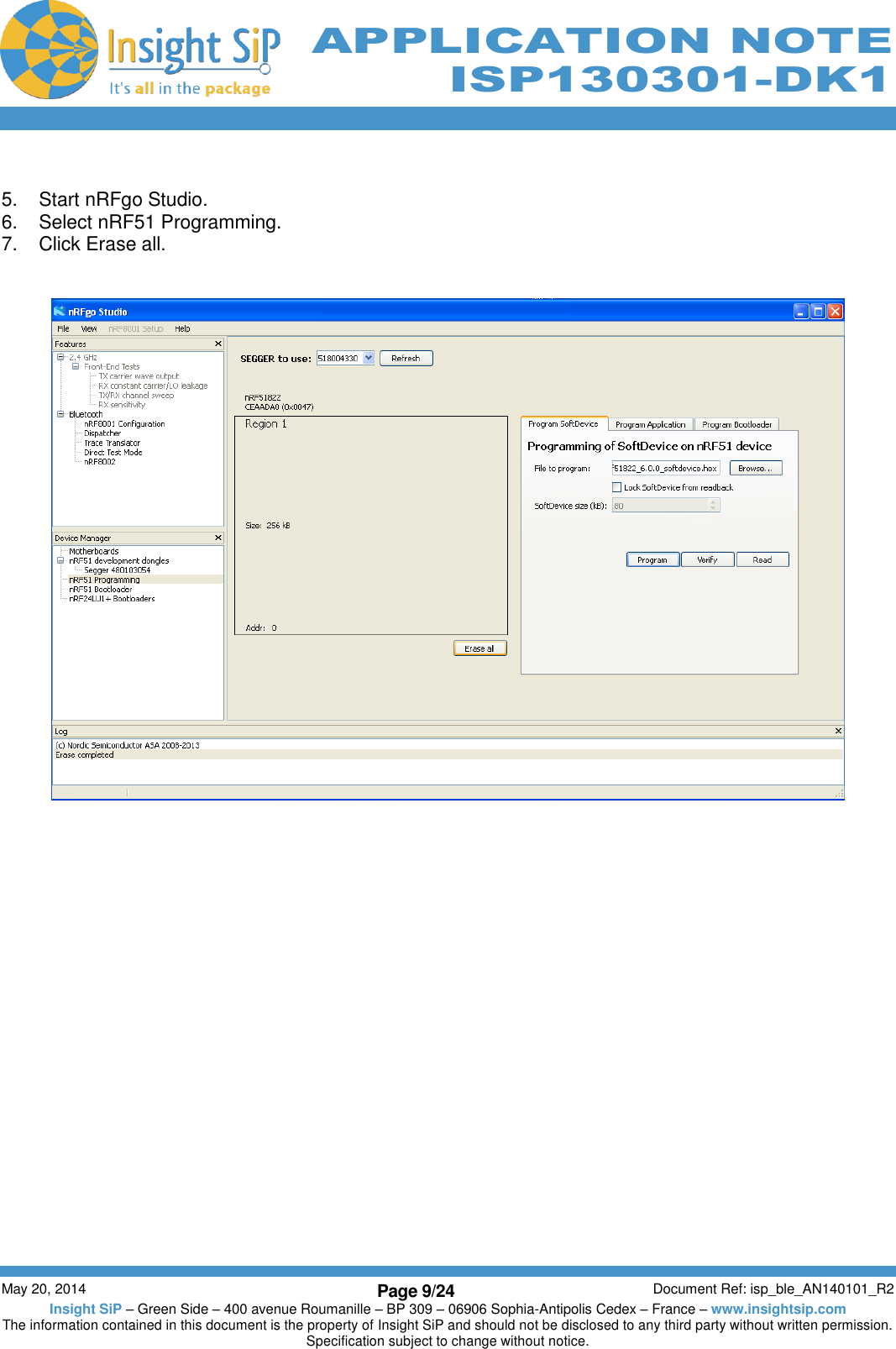
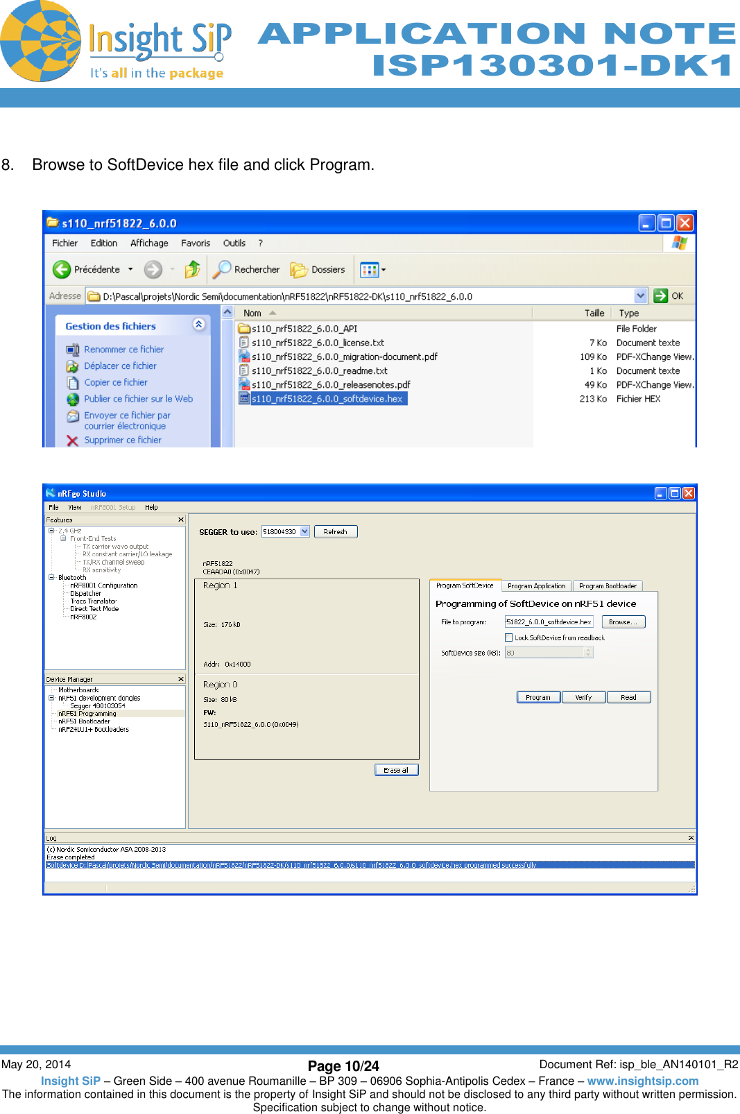
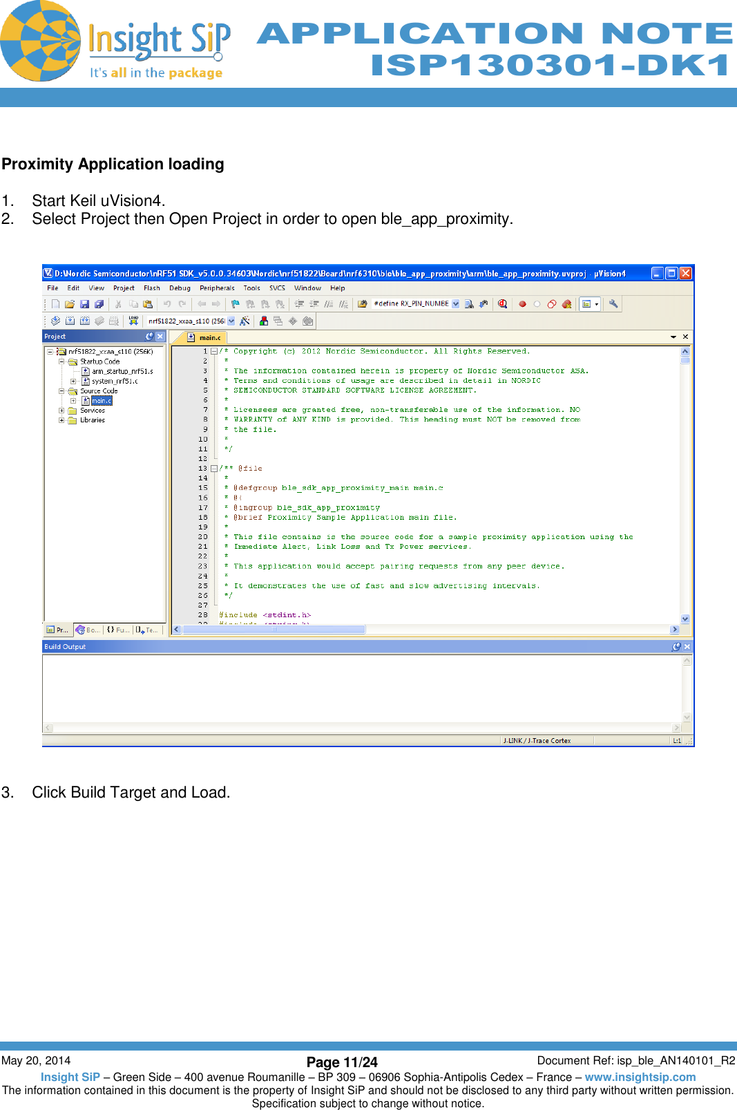
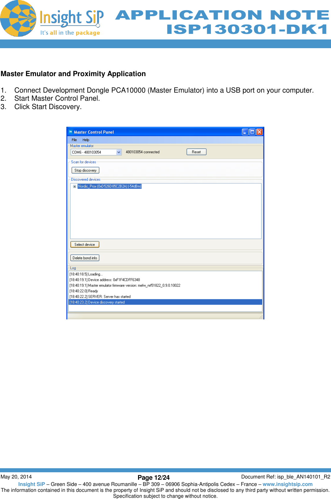
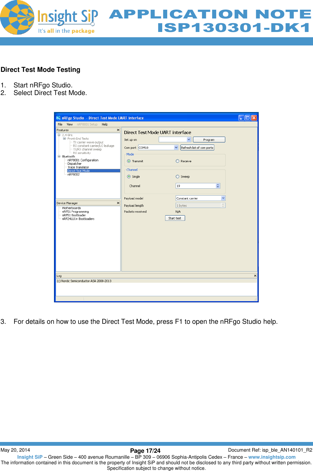
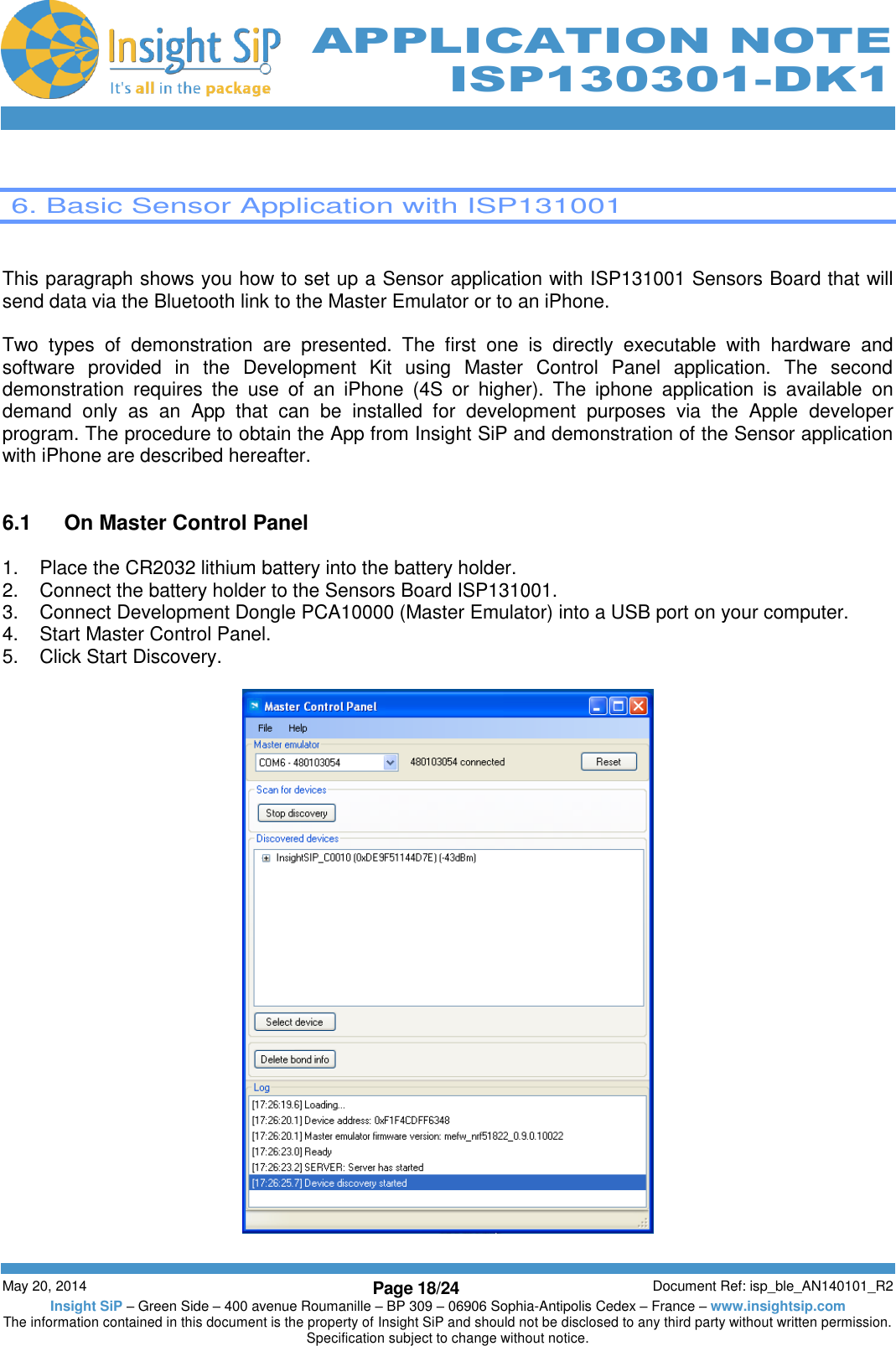
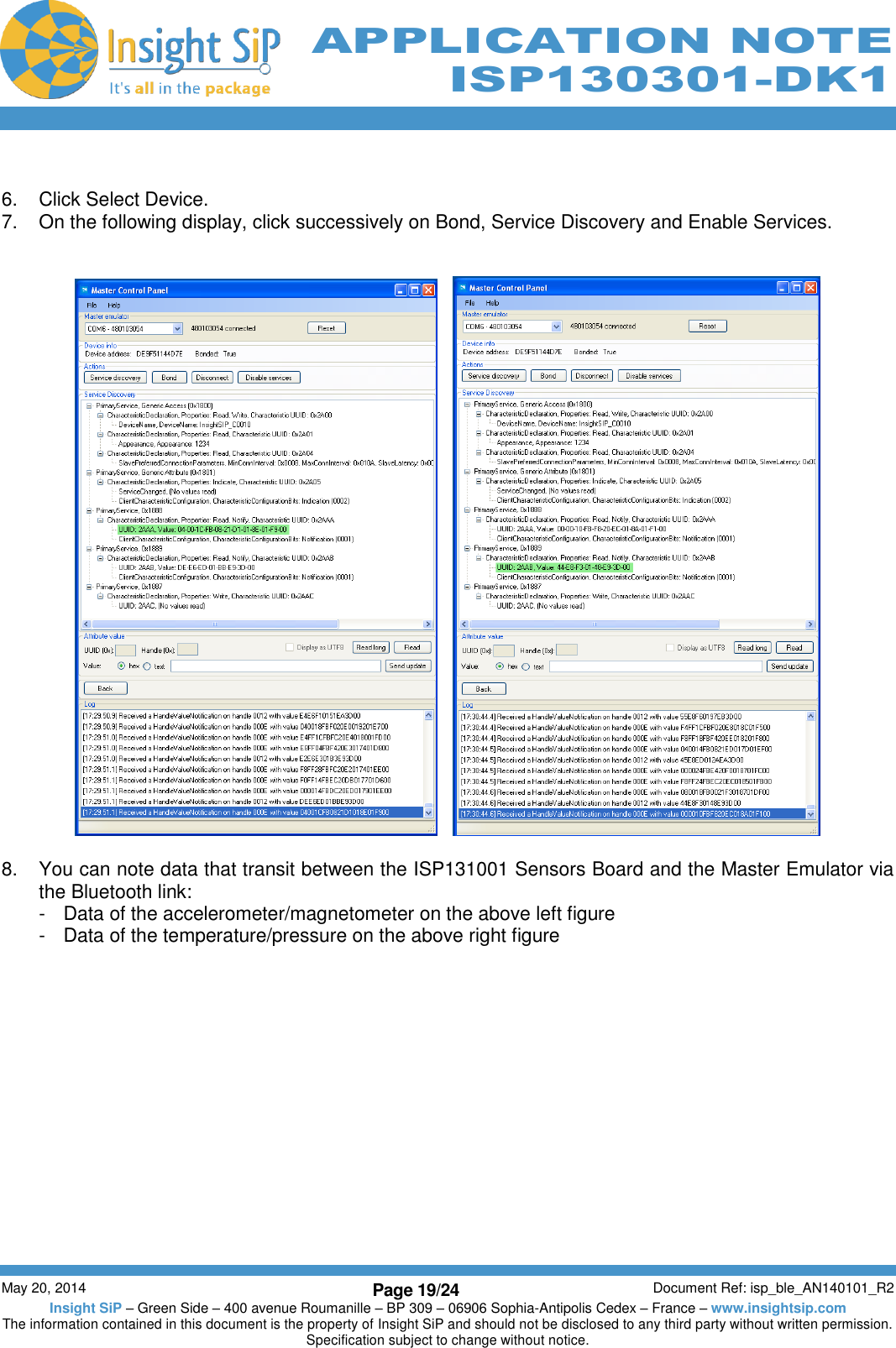
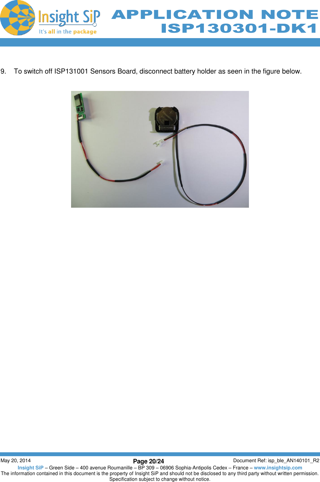
User manual_AN140101R2

         May 20, 2014 Page 1/24 Document Ref: isp_ble_AN140101_R2 Insight SiP – Green Side – 400 avenue Roumanille – BP 309 – 06906 Sophia-Antipolis Cedex – France – www.insightsip.com The information contained in this document is the property of Insight SiP and should not be disclosed to any third party without written permission. Specification subject to change without notice.     APPLICATION NOTE ISP130301-DK1   AN140101 Use of ISP130301-DK1    Introduction  Scope  This document gives details on hardware and software for using and testing Insight SiP Bluetooth Low Energy module ISP130301.  Contents  1. Recommended Documentation ............................................................................................... Page 1-2 2. ISP130301-DK1 Hardware Content ......................................................................................... Page 1-3 3. Software Installation ................................................................................................................ Page 1-4 4. Hardware Description .............................................................................................................. Page 1-5 5. Basic Application using ISP130601 Test Board ....................................................................... Page 1-8 6. Basic Sensor Application with ISP131001 ............................................................................. Page 1-17
         May 20, 2014 Page 2/24 Document Ref: isp_ble_AN140101_R2 Insight SiP – Green Side – 400 avenue Roumanille – BP 309 – 06906 Sophia-Antipolis Cedex – France – www.insightsip.com The information contained in this document is the property of Insight SiP and should not be disclosed to any third party without written permission. Specification subject to change without notice.     APPLICATION NOTE ISP130301-DK1   1. Recommended Documentation   The following Nordic Semiconductor documents and Dev Kits (software portion) are required to understand the complete setup and programming methods:  Documents:    nRF51822 Development kit User Guide (hardware section should be partially ignored – ISP development kit hardware replaces Nordic Semiconductor hardware).   nRF51 Series Reference Manual.    nRF51822 PS (data sheet).    S110 / S120 nRF51822 SoftDevice Specification.    nRF51 SDK.  Dev kits (software portion):    nRFgo Studio.   nRF51 Software Development Kit (SDK): -  Precompiled HEX files. -  Source code. -  Keil ARM project files.    S110 / S120 nRF51822 SoftDevice.    Master Control Panel.  To access these files, go to www.nordicsemi.com and log in to your Nordic My Page account, enter your product key and download the files. Instructions can be found in Chapter 3.  ISP documents that complement the above:    AN140101 App Note – this document.   DS130301 module data sheet.   ISP130601 Test Board schematic SC130602.   ISP131001 Sensors Board schematic SC131002.   ISP130603 Interface Board schematic SC130604.
         May 20, 2014 Page 3/24 Document Ref: isp_ble_AN140101_R2 Insight SiP – Green Side – 400 avenue Roumanille – BP 309 – 06906 Sophia-Antipolis Cedex – France – www.insightsip.com The information contained in this document is the property of Insight SiP and should not be disclosed to any third party without written permission. Specification subject to change without notice.     APPLICATION NOTE ISP130301-DK1   2. ISP130301-DK1 Hardware Content         5 x ISP130301 module samples 1 x J-Link Lite CortexM-9 JTAG/SWD Emulator 1 x nRF51822 Development Dongle (PCA10000) 1 x ISP130601 Test Board 1 x ISP131001 Sensors Board 1 x FPC jumper cable 22 pin 1 x FPC jumper cable 14 pin 1 x FPC jumper cable 10 pin 1 x 10 pin connector 1 x 2-lead patch cable 1 x Battery Holder CR2032 1 x Lithium Battery CR2032 1 x USB cable 1 x 5V power supply 1 x ISP130603 Interface Board
         May 20, 2014 Page 4/24 Document Ref: isp_ble_AN140101_R2 Insight SiP – Green Side – 400 avenue Roumanille – BP 309 – 06906 Sophia-Antipolis Cedex – France – www.insightsip.com The information contained in this document is the property of Insight SiP and should not be disclosed to any third party without written permission. Specification subject to change without notice.     APPLICATION NOTE ISP130301-DK1   3. Software Installation   This paragraph shows you the steps to follow for software installation.  1.  Download and install Keil MDK-ARM Lite from https://www.keil.com/demo/eval/arm.htm to your hard drive.  2.  Download  and  run  the  J-Link  Software  and  documentation  pack  for  Windows  from http://www.segger.com/jlink-software.html. The serial number from your SEGGER J-Link hardware is needed to identify your device and can be found printed on the chip on the J-Link Lite emulator board.  3.  Go to www.nordicsemi.com and log in to your Nordic My Page account.  4.  Select MY KEYS from the left menu. This takes you to the My Keys page.  5.  Enter the product key (included in this kit) into the Product Key field and click Add.  6.  Click MY PRODUCTS in the left menu.  7.  From the Add product dropdown, select the product name and click Add. The chosen product is now listed in the below Overview, My Products table.  8.  In the Overview, My Products table click the Downloads link next to the product name to go directly to the relevant product page download section.  9.  Download, install and run nRFgo Studio.  10.  Download, install and run Master Control Panel. The software is on the CD and if you want the last version, you can find it on the Nordicsemi website. (x86 is for 32 bits windows and x64 is for 64 bits windows)  11.  Download  and  run  the  nRF51  SDK  installer.  Make  sure  to  choose  the  Keil  MDK-ARM  installer option.  12.  Download the S110 / S120 nRF51822 SoftDevice.
         May 20, 2014 Page 5/24 Document Ref: isp_ble_AN140101_R2 Insight SiP – Green Side – 400 avenue Roumanille – BP 309 – 06906 Sophia-Antipolis Cedex – France – www.insightsip.com The information contained in this document is the property of Insight SiP and should not be disclosed to any third party without written permission. Specification subject to change without notice.     APPLICATION NOTE ISP130301-DK1   4. Hardware Description   4.1  ISP130301 Module  ISP130301 is a Bluetooth Low Energy module with integrated antenna.     This  module  is  based  on  Nordic  Semiconductor  nRF51822    2.4  GHz    wireless  SoC.  nRF51822  integrates  nRF51  series  2.4  GHz  transceiver,  a  32  bit  ARM  Cortex™-M0  CPU,  flash  memory,  and analogue and digital peripherals. nRF51822 can support Bluetooth low energy and a range of proprietary 2.4 GHz protocols. The ISP130301 module measures 8 x 11 x 1.2 mm3. The module integrates all the decoupling  capacitors,  the  16  MHz  and  32  kHz  crystals,  their  load  capacitors,  the  DC-DC  converter component, the RF matching circuit and the antenna in addition to the wireless SoC. For more details, see Insight SiP module data sheet (document DS130301).   4.2  ISP130601 Test Board  ISP130601 is the basic application test board that has dimensions of 18 x 30 mm².
         May 20, 2014 Page 6/24 Document Ref: isp_ble_AN140101_R2 Insight SiP – Green Side – 400 avenue Roumanille – BP 309 – 06906 Sophia-Antipolis Cedex – France – www.insightsip.com The information contained in this document is the property of Insight SiP and should not be disclosed to any third party without written permission. Specification subject to change without notice.     APPLICATION NOTE ISP130301-DK1  It encloses:    ISP130301 BLE module   3 x FPC connectors in order to access the nRF51822 GPIOs: -  1 x 10 pin FPC connector on top side of the board. -  1 x 14 pin FPC connector on top side of the board. -  1 x 22 pin FPC connector on bottom side of the board.  The ISP130601 electrical schematic is presented in document SC130602.   4.3  ISP131001 Sensors Board  ISP131001 is the sensor application board that has dimensions of 12.5 x 25 mm².       It encloses:    ISP130301 BLE module.   ST Micro LPS331AP temperature and barometer sensor.   Freescale FXOS8700CQ 6-axis linear accelerometer and magnetometer sensor.   Rohm SML-P11MTT86 mini-LED.   Software to read/drive the sensors.   Removable 10 pin FPC connector for software loading.  The ISP131001 electrical schematic is presented in document SC131002.
         May 20, 2014 Page 7/24 Document Ref: isp_ble_AN140101_R2 Insight SiP – Green Side – 400 avenue Roumanille – BP 309 – 06906 Sophia-Antipolis Cedex – France – www.insightsip.com The information contained in this document is the property of Insight SiP and should not be disclosed to any third party without written permission. Specification subject to change without notice.     APPLICATION NOTE ISP130301-DK1  4.4  ISP130603 Interface Board  ISP130603 is the application type interface board that has dimensions of 86 x 80 mm².                               The ISP130603 electrical schematic is presented in document SC130604.   4.5  nRF51822 Development Dongle (PCA10000)  The  reader  should  refer  to  the  corresponding  paragraph  in  nRF51822  Development  Kit  User  Guide document.     Current measurement pins Reset button Supply connector 5V DC Not used RS232 serial port connector Voltage measurement pins JTAG connector 10 pin FPC connector 14 pin FPC connector 22 pin FPC connector Set App Vcc (Vcc in mV = 500 + Jumpers) Equivalent to PORT0 on nRFgo Motherboard   Equivalent to PORT1 on nRFgo Motherboard Equivalent to PORT2 on nRFgo  Motherboard Equivalent to PORT3 on nRFgo Motherboard App Vcc  enable jumper  RS232 port header (RXD and TXD) RS232 port header (RTS and CTS)
         May 20, 2014 Page 8/24 Document Ref: isp_ble_AN140101_R2 Insight SiP – Green Side – 400 avenue Roumanille – BP 309 – 06906 Sophia-Antipolis Cedex – France – www.insightsip.com The information contained in this document is the property of Insight SiP and should not be disclosed to any third party without written permission. Specification subject to change without notice.     APPLICATION NOTE ISP130301-DK1   5. Basic Application using ISP130601 Test Board   5.1  Basic BLE Proximity Application  This paragraph shows you how to set up and program a BLE proximity application on top of a SoftDevice that will send data on a Bluetooth link from the ISP130601 Test Board to the Master Emulator. In order to use Bluetooth Low Energy radio, the software is loaded in 2 parts:    S110 / S120 SoftDevice using nRFgo Studio (hex file, no source).   Proximity Application using Keil uVision4.  Then Master Emulator is connected and Proximity Application is launched.   S110 / S120 SoftDevice loading  1.  Connect the SEGGER J-Link board to the ISP130603 Interface Board with the 10 pin flat cable (1.27 mm pitch, provided in the Development Kit). 2.  Connect the provided USB cable from the J-link board to your computer. 3.  Connect the ISP130602 Test Board to the ISP130603 Interface Board with the 10 pin, 14 pin and 22 pin FPC jumper cables (0.5 mm pitch, provided in the Development Kit) 4.  To ensure that power supply starts correctly, disconnect Enable jumper, connect to OFF and then Enable after supplying 5V from DC power supply (provided in the Development kit).
         May 20, 2014 Page 9/24 Document Ref: isp_ble_AN140101_R2 Insight SiP – Green Side – 400 avenue Roumanille – BP 309 – 06906 Sophia-Antipolis Cedex – France – www.insightsip.com The information contained in this document is the property of Insight SiP and should not be disclosed to any third party without written permission. Specification subject to change without notice.     APPLICATION NOTE ISP130301-DK1  5.  Start nRFgo Studio. 6.  Select nRF51 Programming. 7.  Click Erase all.
         May 20, 2014 Page 10/24 Document Ref: isp_ble_AN140101_R2 Insight SiP – Green Side – 400 avenue Roumanille – BP 309 – 06906 Sophia-Antipolis Cedex – France – www.insightsip.com The information contained in this document is the property of Insight SiP and should not be disclosed to any third party without written permission. Specification subject to change without notice.     APPLICATION NOTE ISP130301-DK1  8.  Browse to SoftDevice hex file and click Program.
         May 20, 2014 Page 11/24 Document Ref: isp_ble_AN140101_R2 Insight SiP – Green Side – 400 avenue Roumanille – BP 309 – 06906 Sophia-Antipolis Cedex – France – www.insightsip.com The information contained in this document is the property of Insight SiP and should not be disclosed to any third party without written permission. Specification subject to change without notice.     APPLICATION NOTE ISP130301-DK1  Proximity Application loading  1.  Start Keil uVision4. 2.  Select Project then Open Project in order to open ble_app_proximity.      3.  Click Build Target and Load.
         May 20, 2014 Page 12/24 Document Ref: isp_ble_AN140101_R2 Insight SiP – Green Side – 400 avenue Roumanille – BP 309 – 06906 Sophia-Antipolis Cedex – France – www.insightsip.com The information contained in this document is the property of Insight SiP and should not be disclosed to any third party without written permission. Specification subject to change without notice.     APPLICATION NOTE ISP130301-DK1  Master Emulator and Proximity Application  1.  Connect Development Dongle PCA10000 (Master Emulator) into a USB port on your computer. 2.  Start Master Control Panel. 3.  Click Start Discovery.
         May 20, 2014 Page 13/24 Document Ref: isp_ble_AN140101_R2 Insight SiP – Green Side – 400 avenue Roumanille – BP 309 – 06906 Sophia-Antipolis Cedex – France – www.insightsip.com The information contained in this document is the property of Insight SiP and should not be disclosed to any third party without written permission. Specification subject to change without notice.     APPLICATION NOTE ISP130301-DK1  4. If you have an error message as indicated in the photo :    It  means  that  the  nRF51822  Development  Dongle  (PCA10000)  is  not  programmed.  For  your information, please  refer  to  the nRF51822  Development  Kit  User  Guide document as  indicated  in our application note ISP130301-DK1 part  4.5  on page 14-7.  You can find this user guide on the Nordicsemi website. The procedure to program the dongle (PCA10000) is described on page 13. I enclose a copy of the user guide for your convenience.  1)  Open  the  Master  Control  Panel  from  the  Start  menu  (Start  >  All  Programs  >  Nordic Semiconductor > Master Control Panel). 2)  Make sure the Development Dongle is detected. The Master Emulator item list should show COMnn-xxxxxxxxx  (nn  gives  the  COM  port  number;  xxxxxxxxx  is  the  SEGGER serial     number printed on the dongle). Restart the application if it doesn’t appear in the item list. Before continuing, make sure you have selected the correct device by verifying the serial number in the item list with the serial number printed on the Development Dongle. 3)  When  you  use  the  Development  Dongle  for  the  first  time,  you  must  first  program  it with the Master Emulator Firmware. a.  In the Master Control Panel menu click File and select Flash Programming. b.  Click Browse. This opens a browser that automatically points to the location of the c.  mefw_nrf51822_<version>_firmware.hex (<version> will be replaced by a number d.  giving the version of the actual firmware). e. The Master Control Panel Firmware file is located in: f. C:\Program  Files  (x86)  \  Nordic  Semiconductor  \  Master  Control  Panel  \<version>\firmware\ g.  pca10000\MEFW_nRF51822_<version>_firmware.hex. h.  Select the Master Emulator Firmware file and click Open. i.  Click Program to start programming the selected device. j.  When the programming is finished click Exit to go back to the main window.  5.  Click Select Device. 6.  On the following display, click successively on Bond, Service Discovery and Enable Services.
         May 20, 2014 Page 14/24 Document Ref: isp_ble_AN140101_R2 Insight SiP – Green Side – 400 avenue Roumanille – BP 309 – 06906 Sophia-Antipolis Cedex – France – www.insightsip.com The information contained in this document is the property of Insight SiP and should not be disclosed to any third party without written permission. Specification subject to change without notice.     APPLICATION NOTE ISP130301-DK1     7.  You can note Battery voltage is sent by the ISP130601 Test Board to the Master Emulator via the Bluetooth link. The application is written to send a value that changes cyclically.
         May 20, 2014 Page 15/24 Document Ref: isp_ble_AN140101_R2 Insight SiP – Green Side – 400 avenue Roumanille – BP 309 – 06906 Sophia-Antipolis Cedex – France – www.insightsip.com The information contained in this document is the property of Insight SiP and should not be disclosed to any third party without written permission. Specification subject to change without notice.     APPLICATION NOTE ISP130301-DK1  5.2  Direct Test Mode (UART)  This  paragraph  shows  you  how  to  set  up  and  program  the  Direct  Test  Mode  through  the  UART  on ISP130601 Test Board.   Direct Test Mode Set-up  1.  Connect the SEGGER J-Link board to the ISP130603 Interface Board with the 10 pin flat cable (1.27 mm pitch, provided in the Development Kit). 2.  Connect the USB cable from the J-link board to your computer. 3.  Connect the ISP130601 Test Board to the ISP130603 Interface Board with the 10 pin, 14 pin and 22 pin FPC jumper cables (0.5 mm pitch, provided in the Development Kit) 4.  On  the  ISP130603  Interface  Board,  connect  the  2-lead  patch  cable  in  order  to  connect  RXD  to P0_16 and TXD to P0_17. Make sure the RXD/TXD labels match for each wire. This matches the default setting in the SDK project ble_app_dtm (be careful: depending on the ble_app_dtm version, the ports used could be different). 5.  Connect a USB to serial cable converter  from  RS232  port  connector of the ISP130603  Interface Board to a USB port on your computer. 6.  Connect the 5V DC power supply to the ISP130603 Interface Board.
         May 20, 2014 Page 16/24 Document Ref: isp_ble_AN140101_R2 Insight SiP – Green Side – 400 avenue Roumanille – BP 309 – 06906 Sophia-Antipolis Cedex – France – www.insightsip.com The information contained in this document is the property of Insight SiP and should not be disclosed to any third party without written permission. Specification subject to change without notice.     APPLICATION NOTE ISP130301-DK1  Direct Test Mode Loading  1.  Start Keil uVision4. 2.  Select Project then Open Project in order to open ble_app_dtm.      3.  Click Build Target and Load.
         May 20, 2014 Page 17/24 Document Ref: isp_ble_AN140101_R2 Insight SiP – Green Side – 400 avenue Roumanille – BP 309 – 06906 Sophia-Antipolis Cedex – France – www.insightsip.com The information contained in this document is the property of Insight SiP and should not be disclosed to any third party without written permission. Specification subject to change without notice.     APPLICATION NOTE ISP130301-DK1  Direct Test Mode Testing  1.  Start nRFgo Studio. 2.  Select Direct Test Mode.      3.  For details on how to use the Direct Test Mode, press F1 to open the nRFgo Studio help.
         May 20, 2014 Page 18/24 Document Ref: isp_ble_AN140101_R2 Insight SiP – Green Side – 400 avenue Roumanille – BP 309 – 06906 Sophia-Antipolis Cedex – France – www.insightsip.com The information contained in this document is the property of Insight SiP and should not be disclosed to any third party without written permission. Specification subject to change without notice.     APPLICATION NOTE ISP130301-DK1   6. Basic Sensor Application with ISP131001   This paragraph shows you how to set up a Sensor application with ISP131001 Sensors Board that will send data via the Bluetooth link to the Master Emulator or to an iPhone.  Two  types  of  demonstration  are  presented.  The  first  one  is  directly  executable  with  hardware  and software  provided  in  the  Development  Kit  using  Master  Control  Panel  application.  The  second demonstration  requires  the  use  of  an  iPhone  (4S  or  higher).  The  iphone  application  is  available  on demand  only  as  an  App  that  can  be  installed  for  development  purposes  via  the  Apple  developer program. The procedure to obtain the App from Insight SiP and demonstration of the Sensor application with iPhone are described hereafter.    6.1  On Master Control Panel  1.  Place the CR2032 lithium battery into the battery holder. 2.  Connect the battery holder to the Sensors Board ISP131001. 3.  Connect Development Dongle PCA10000 (Master Emulator) into a USB port on your computer. 4.  Start Master Control Panel. 5.  Click Start Discovery.
         May 20, 2014 Page 19/24 Document Ref: isp_ble_AN140101_R2 Insight SiP – Green Side – 400 avenue Roumanille – BP 309 – 06906 Sophia-Antipolis Cedex – France – www.insightsip.com The information contained in this document is the property of Insight SiP and should not be disclosed to any third party without written permission. Specification subject to change without notice.     APPLICATION NOTE ISP130301-DK1  6.  Click Select Device. 7.  On the following display, click successively on Bond, Service Discovery and Enable Services.         8.  You can note data that transit between the ISP131001 Sensors Board and the Master Emulator via the Bluetooth link:  -  Data of the accelerometer/magnetometer on the above left figure -  Data of the temperature/pressure on the above right figure
         May 20, 2014 Page 20/24 Document Ref: isp_ble_AN140101_R2 Insight SiP – Green Side – 400 avenue Roumanille – BP 309 – 06906 Sophia-Antipolis Cedex – France – www.insightsip.com The information contained in this document is the property of Insight SiP and should not be disclosed to any third party without written permission. Specification subject to change without notice.     APPLICATION NOTE ISP130301-DK1  9.  To switch off ISP131001 Sensors Board, disconnect battery holder as seen in the figure below.
         May 20, 2014 Page 21/24 Document Ref: isp_ble_AN140101_R2 Insight SiP – Green Side – 400 avenue Roumanille – BP 309 – 06906 Sophia-Antipolis Cedex – France – www.insightsip.com The information contained in this document is the property of Insight SiP and should not be disclosed to any third party without written permission. Specification subject to change without notice.     APPLICATION NOTE ISP130301-DK1  6.2 On iPhone Device (4S or higher)  The Sensor application is available on demand from Insight SiP. The iPhone App is a demonstration App that is provided "as is" in order to demonstrate the Smart Bluetooth sensor node. Only one iPhone is allowed per development kit.  The installation procedure for the Sensor application is described hereafter:  1.  Contact Insight SiP at contact@insightsip.com and communicate the UDID of your iPhone device (4S or higher). The UDID is available when connecting your iPhone to you computer and starting iTunes on your computer.      2.  Once you receive reply from Insight SiP, open Safari web browser on your iPhone device. 3.  Open the URL link provided by Insight SiP. 4.  The InsightSiPDemo application is downloaded and installed. You should see the following screen on your iPhone device.
         May 20, 2014 Page 22/24 Document Ref: isp_ble_AN140101_R2 Insight SiP – Green Side – 400 avenue Roumanille – BP 309 – 06906 Sophia-Antipolis Cedex – France – www.insightsip.com The information contained in this document is the property of Insight SiP and should not be disclosed to any third party without written permission. Specification subject to change without notice.     APPLICATION NOTE ISP130301-DK1  Then you will be able to set up the application demonstration as follows:  1.  Place the CR2032 lithium battery into the battery holder. 2.  Connect the battery holder to the Sensors Board ISP131001. 3.  Start  InsightSiPDemo  application  on  your  iPhone,  click  Connect  and  select  your  Sensors  Board (name is InsightSiP_xxxxx).                4.  Click Accelerometer. A Calibration phase invites you to rotate the ISP131001 Sensors Board. Then, a starship on your iPhone screen follows the Sensors board movement.
         May 20, 2014 Page 23/24 Document Ref: isp_ble_AN140101_R2 Insight SiP – Green Side – 400 avenue Roumanille – BP 309 – 06906 Sophia-Antipolis Cedex – France – www.insightsip.com The information contained in this document is the property of Insight SiP and should not be disclosed to any third party without written permission. Specification subject to change without notice.     APPLICATION NOTE ISP130301-DK1  5.  Click Back and Temperature to start temperature and pressure demonstration.      6.  Click Back and LED. A prompt will invite you to pair the Sensors Board with the iPhone. Click Pair. The LED lights up.
         May 20, 2014 Page 24/24 Document Ref: isp_ble_AN140101_R2 Insight SiP – Green Side – 400 avenue Roumanille – BP 309 – 06906 Sophia-Antipolis Cedex – France – www.insightsip.com The information contained in this document is the property of Insight SiP and should not be disclosed to any third party without written permission. Specification subject to change without notice.     APPLICATION NOTE ISP130301-DK1  7.  To switch off ISP131001 Sensors Board, disconnect battery holder as seen in the figure below.

Navigation menu