Integrated Microwave Technologies 23GP2-L5 Video Booster Amplifier User Manual 3
Integrated Microwave Technologies, LLC. Video Booster Amplifier Users Manual 3
Contents
- 1. Users Manual 1
- 2. Users Manual 2
- 3. Users Manual 3
- 4. Users Manual 4
Users Manual 3

GoPac Theory of Operation
M13-0002-00A Rev D.3 11 User Manual
2. THEORY OF OPERATION
The GoPac Power amplifier has been designed
to receive the output from a low power
transmitter and amplify it. The following
discussion assumes that the external
transmitter has output power less than 250mW
and has been verified to abide by all FCC
rules and regulations.
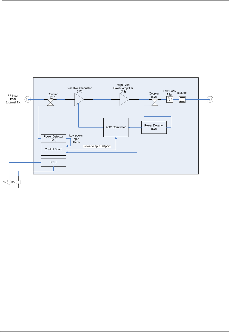
The RF output from the low power transmitter
is applied to the RF Input Connector (J1) as
shown in Figure 1. The signal is passed
through a power coupler (C1). This coupler
feeds two circuits: a variable attenuator (U1),
and a power detector (D1). This power
detector (the first of two) is designed to detect
the presence of an RF signal at J1. If the
signal is too high or too low, the main power
amplifier (A1) will be forced into standby by
the internal controller. This is to prevent the
power amplifier from going into transmit
mode without a signal applied, or with a signal
that is too high for the system to handle.
Power control:
After the RF signal from the coupler (C1) is
applied to variable attenuator (U1), it is routed
to a high gain high power amplifier (A1). The
output of the amplifier is then applied to a
power couple (C2). A portion of the output
power is applied to a second power detector
(D2) that is then fed back through an
automatic gain control loop (AGC). The
output of the AGC loop controls the variable
attenuator. An analog signal from the
microprocessor is applied to the AGC
controller. This signal is compared to the
power level from the main power detector
(D2). If the signal from (D2) is higher than
the signal from the microprocessor, the
attenuator is increased therefore reducing the
total output power, reducing the voltage from
(D2). If the signal from (D2) is lower than the
signal from the microprocessor, the attenuator
is reduced therefore increasing the total output
power, and increasing the voltage from (D2).
This process is performed continuously until a
steady state output power has been reached.
Main RF output:
The RF output from the amplifier is routed
through a low pass filter and an output
isolator. The low pass filter is used to remove
any unwanted harmonics created inside the
power amplifier. The output isolator is used
to protect the power amplifier from being
damaged when devices with poor RF match
are applied.
GoPac Theory of Operation
M13-0002-00A Rev D.3 12 User Manual
Figure 1: System Block Diagram

GoPac Specifications
M13-0002-00A Rev D.3 13 User Manual
3. SPECIFICATIONS
RF Performance
Frequency band:......................................................1.99 GHz – 2.70 GHz
.................................................................................6.40 GHz – 7.10 GHz
Frequency tuning step size:.....................................50 KHz (United States)
RF Output Power: ...................................................1 to 5W (digital) standard (8W optional)
RF Power Modes
Standby: ..................................................................No RF out
Tx:...........................................................................Instant on-frequency transmission
Stability:..................................................................+/– 2.5 PPM
Power Requirements
Input Range.............................................................90 to 240 VAC (40 to 60Hz), or +11 to +32 VDC
(without the need for internal jumpers or switch settings)
Consumption:..........................................................80 watts (with attached camera back transmitter)
Physical Characteristics
Dimensions: ............................................................6.8”(17.27cm) x 13”(33cm) x 17”(43.2cm)
Weight:....................................................................8.8 lbs (4 kg)
Environmental
Temperature:...........................................................-20°C to +65°C (operational)
Humidity: ................................................................95% (+10°C to +50°C)
Connectors
Power ......................................................................Multi-pin MS Type(Detoronics DT02H-14-18PN)
RF:...........................................................................Type “N” (Female) (50 ohms)

GoPac Specifications
M13-0002-00A Rev D.3 14 User Manual

GoPac Installation
M13-0002-00A Rev D.3 15 User Manual
4. INSTALLATION
4.1 UNPACKING & INSPECTION
Unpack and visually inspect the unit for LCD,
connector, and surface area damage. All
claims should be filed with the carrier. Save
all shipping and packing materials for possible
re-use.
4.2 MECHANICAL INSTALLATION
The GoPac comes standard with an Anton
Bauer Mounting Bracket Assembly. This
allows a camera back transmitter to be quickly
attached or removed from the docking station.
To mount a camera back transmitter to the
GoPac, perform the following:
1. Orient the camera back transmitter
mounting slots to align with the GoPac
guide pins as shown in (Figure 2).
2. Slide the camera back transmitter onto the
GoPac guide pins until you hear the
thumb-catch lock. Ensure that there is no
play between the camera back transmitter
and the GoPac.
3. Connect an appropriate RF jumper
between the RF output of the camera back
transmitter, and the RF input of the GoPac.
(Figure 3).
To connect a power source to GoPac:
The built-in power supply accepts 90 to 240
VAC (40 to 60 Hz) or +11 VDC to
+32 VDC without requiring any jumper or
switch settings.
Nucomm ships a DC cable, and the
appropriate local AC line cord. Alternate line
cords are available upon request.
Connect the supplied cable between an
appropriate power source and the GoPac front
panel power connector. (Figures 4 & 5).
CIRCUIT BREAKERS
The GoPac is protected against over/under
voltage and reverse polarity conditions. The
unit has AC & DC circuit breakers, as shown
in Figure 4. The breakers will trip at 10
Amps.
If a breaker trips, check and verify all power
connections and specs, then reset the breaker
by pushing it back into position.
GoPac Installation
M13-0002-00A Rev D.3 16 User Manual
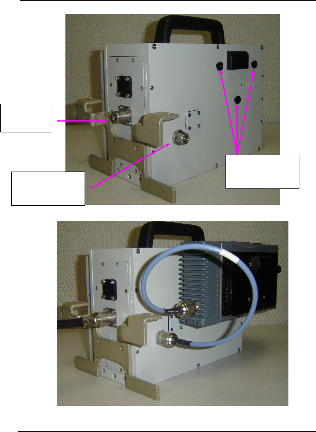
Figure 2: GoPac Guide Pins & RF Connectors
Figure 3: GoPac fitted with RF cables
RF Output
(to antenna)
RF Input
(from camera back
transmitter, e.g.)
Guide pins for
mounting camera
back transmitter